EP3667014A1 - Ringförmige barriere - Google Patents
Ringförmige barriere Download PDFInfo
- Publication number
- EP3667014A1 EP3667014A1 EP18212358.8A EP18212358A EP3667014A1 EP 3667014 A1 EP3667014 A1 EP 3667014A1 EP 18212358 A EP18212358 A EP 18212358A EP 3667014 A1 EP3667014 A1 EP 3667014A1
- Authority
- EP
- European Patent Office
- Prior art keywords
- tubular
- split ring
- expandable metal
- expandable
- metal
- Prior art date
- Legal status (The legal status is an assumption and is not a legal conclusion. Google has not performed a legal analysis and makes no representation as to the accuracy of the status listed.)
- Withdrawn
Links
- 230000004888 barrier function Effects 0.000 title claims abstract description 87
- 239000002184 metal Substances 0.000 claims abstract description 288
- 229910052751 metal Inorganic materials 0.000 claims abstract description 288
- 238000007789 sealing Methods 0.000 claims abstract description 83
- 238000004804 winding Methods 0.000 claims abstract description 40
- 238000002955 isolation Methods 0.000 claims abstract description 9
- 239000000463 material Substances 0.000 claims description 14
- 239000012530 fluid Substances 0.000 description 44
- 238000004891 communication Methods 0.000 description 20
- 229920001343 polytetrafluoroethylene Polymers 0.000 description 16
- 239000004810 polytetrafluoroethylene Substances 0.000 description 16
- 239000003921 oil Substances 0.000 description 10
- 229920001971 elastomer Polymers 0.000 description 9
- 230000001965 increasing effect Effects 0.000 description 9
- 229920000642 polymer Polymers 0.000 description 8
- -1 polytetrafluoroethylene Polymers 0.000 description 8
- 239000007769 metal material Substances 0.000 description 6
- 239000000806 elastomer Substances 0.000 description 5
- 239000007789 gas Substances 0.000 description 5
- VNWKTOKETHGBQD-UHFFFAOYSA-N methane Chemical compound C VNWKTOKETHGBQD-UHFFFAOYSA-N 0.000 description 4
- 239000004033 plastic Substances 0.000 description 4
- 239000005060 rubber Substances 0.000 description 4
- 230000007423 decrease Effects 0.000 description 3
- 238000004519 manufacturing process Methods 0.000 description 3
- XLYOFNOQVPJJNP-UHFFFAOYSA-N water Substances O XLYOFNOQVPJJNP-UHFFFAOYSA-N 0.000 description 3
- XEEYBQQBJWHFJM-UHFFFAOYSA-N Iron Chemical compound [Fe] XEEYBQQBJWHFJM-UHFFFAOYSA-N 0.000 description 2
- PXHVJJICTQNCMI-UHFFFAOYSA-N Nickel Chemical compound [Ni] PXHVJJICTQNCMI-UHFFFAOYSA-N 0.000 description 2
- 230000015572 biosynthetic process Effects 0.000 description 2
- 238000009750 centrifugal casting Methods 0.000 description 2
- 239000010779 crude oil Substances 0.000 description 2
- 230000003247 decreasing effect Effects 0.000 description 2
- 238000003754 machining Methods 0.000 description 2
- 239000000203 mixture Substances 0.000 description 2
- 239000003345 natural gas Substances 0.000 description 2
- 238000004528 spin coating Methods 0.000 description 2
- 239000010935 stainless steel Substances 0.000 description 2
- 229910001220 stainless steel Inorganic materials 0.000 description 2
- 229910001369 Brass Inorganic materials 0.000 description 1
- OKTJSMMVPCPJKN-UHFFFAOYSA-N Carbon Chemical compound [C] OKTJSMMVPCPJKN-UHFFFAOYSA-N 0.000 description 1
- 239000004215 Carbon black (E152) Substances 0.000 description 1
- 229910000975 Carbon steel Inorganic materials 0.000 description 1
- RYGMFSIKBFXOCR-UHFFFAOYSA-N Copper Chemical compound [Cu] RYGMFSIKBFXOCR-UHFFFAOYSA-N 0.000 description 1
- 229910000831 Steel Inorganic materials 0.000 description 1
- ATJFFYVFTNAWJD-UHFFFAOYSA-N Tin Chemical compound [Sn] ATJFFYVFTNAWJD-UHFFFAOYSA-N 0.000 description 1
- 239000004411 aluminium Substances 0.000 description 1
- 229910052782 aluminium Inorganic materials 0.000 description 1
- XAGFODPZIPBFFR-UHFFFAOYSA-N aluminium Chemical compound [Al] XAGFODPZIPBFFR-UHFFFAOYSA-N 0.000 description 1
- 238000005452 bending Methods 0.000 description 1
- 239000010951 brass Substances 0.000 description 1
- 239000010962 carbon steel Substances 0.000 description 1
- 229910052802 copper Inorganic materials 0.000 description 1
- 239000010949 copper Substances 0.000 description 1
- 238000005520 cutting process Methods 0.000 description 1
- 230000000694 effects Effects 0.000 description 1
- 230000002708 enhancing effect Effects 0.000 description 1
- 238000000227 grinding Methods 0.000 description 1
- 229930195733 hydrocarbon Natural products 0.000 description 1
- 150000002430 hydrocarbons Chemical class 0.000 description 1
- 229910052742 iron Inorganic materials 0.000 description 1
- 239000011499 joint compound Substances 0.000 description 1
- 239000011133 lead Substances 0.000 description 1
- 238000000034 method Methods 0.000 description 1
- 238000003801 milling Methods 0.000 description 1
- 238000012986 modification Methods 0.000 description 1
- 230000004048 modification Effects 0.000 description 1
- 229910052759 nickel Inorganic materials 0.000 description 1
- 239000010959 steel Substances 0.000 description 1
- 239000000126 substance Substances 0.000 description 1
- 239000011135 tin Substances 0.000 description 1
- 230000007704 transition Effects 0.000 description 1
- 230000003313 weakening effect Effects 0.000 description 1
Images




Classifications
-
- E—FIXED CONSTRUCTIONS
- E21—EARTH OR ROCK DRILLING; MINING
- E21B—EARTH OR ROCK DRILLING; OBTAINING OIL, GAS, WATER, SOLUBLE OR MELTABLE MATERIALS OR A SLURRY OF MINERALS FROM WELLS
- E21B33/00—Sealing or packing boreholes or wells
- E21B33/10—Sealing or packing boreholes or wells in the borehole
- E21B33/12—Packers; Plugs
- E21B33/127—Packers; Plugs with inflatable sleeve
- E21B33/1277—Packers; Plugs with inflatable sleeve characterised by the construction or fixation of the sleeve
Definitions
- annular barriers are used for providing a zonal isolation of the annulus between the casing and the wall of another casing or the wall of the borehole, or for providing a liner hanger.
- the split ring-shaped support element may be made of a metallic material.
- the split ring-shaped support element in the second circumferential groove or the third circumferential groove may be comprised of several separate parts, where each part of the split ring-shaped support element has at least two windings.
- the ring-shaped support element may be one split ring.
- the end sleeve may be made of a metal material having a different yield strength than that of the expandable metal tubular.
- end sleeve may have a yield strength being twice as high as the yield strength of the expandable metal tubular.
- end sleeve may be welded onto the outer face of the expandable metal tubular.
- the expandable metal tubular at the second end may comprise another end sleeve surrounding the expandable metal tubular in order to hinder free expansion of the second end.
- end sleeve may abut the expandable metal tubular, the first end of the end sleeve being welded onto the outer face of the tubular metal part.
- each of the plurality of sealing units may comprise both the sealing element and a split ring-shaped retaining element arranged in the first circumferential grooves, the split ring-shaped retaining element forming a back-up for the sealing element, and the split ring-shaped retaining element having more than one winding, so that when the expandable metal tubular is expanded from the first outer diameter to the second outer diameter, the split ring-shaped retaining element partly unwinds.
- the split ring-shaped retaining element may ensure that the sealing element is maintained in the longitudinal extension of the expandable metal tubular even when it is being expanded, so that the sealing element retains its intended position and the sealing properties of the expandable metal tubular are enhanced.
- the sealing element may withstand a higher pressure on the side where the split ring-shaped retaining element is positioned, since the split ring-shaped retaining element functions as a back-up and support system for the sealing element.
- an intermediate element may be arranged between the split ring-shaped support element and the groove part.
- the tubular metal element may be connecting the expandable metal tubular with the tubular metal part, where the first end part of the tubular metal element is connected with the tubular metal part, and the second end part is connected with the expandable metal tubular, the expandable metal tubular can be expanded without substantially thinning.
- the tubular metal element is flexing, hence providing the sleeve with an additional flexing ability. If the expandable metal tubular was just bent at its ends, the bend would unbend, which would generate an extremely high stress in the connection between the expandable metal tubular and the tubular metal part, which may result in a crack in the connection to the tubular metal part and hence a leaking annular barrier.
- the element By having the tubular metal element fastened so that the first end part is arranged closer to the sealing units along the longitudinal extension of the tubular metal part than the second end part, the element seeks to keep the angle between the tubular metal element and the tubular metal part at a minimum during expansion of the annular barrier.
- tubular metal part may have an opening fluidly connected with the expandable space for allowing fluid from within the tubular metal part to the expandable space to expand the expandable metal tubular.
- tubular metal element may be made as a separate element, the first end part subsequently being connected to the tubular metal part and the second end part being connected to the expandable metal tubular.
- first end part of the tubular metal element may be welded to the tubular metal part and/or the second end part of the tubular metal element may be welded to the expandable metal tubular.
- the split ring-shaped retaining element may be arranged in an abutting manner to the sealing element.
- the split ring-shaped retaining element may preferably be made of material having a yield strength of at least 70 MPa, preferably at least 100 MPa, more preferably at least 200 MPa.
- the split ring-shaped retaining element may unwind by less than one winding when the expandable metal tubular is expanded from the first outer diameter to the second outer diameter.
- the split ring-shaped retaining element may have a plurality of windings.
- the expandable metal tubular may have a first thickness in the first circumferential groove between a first and a second circumferential edge and a second thickness in adjacent areas, the first thickness being smaller than the second thickness.
- split ring-shaped retaining element and the sealing element may substantially fill a gap provided between the first and second circumferential edges.
- the split ring-shaped retaining element may be made of a metallic material.
- split ring-shaped retaining element may be made of a spring material.
- the split ring-shaped retaining element may retain the sealing element in a position along the longitudinal extension of the expandable metal tubular while expanding the split ring-shaped retaining element and the sealing element.
- the windings of the split ring-shaped retaining element or the windings of the split ring-shaped support element may be helically wound around the expandable metal tubular.
- the windings of the split ring-shaped retaining element or the windings of the split ring-shaped support element may have a square cross-section.
- the sealing element may be partially cone-shaped.
- circumferential edges may be extending in a radial extension in relation to the expandable metal tubular, said radial extension being perpendicular to the longitudinal extension of the expandable metal tubular.
- Said split ring-shaped retaining element may partly overlap the intermediate element.
- sealing element may be made of an elastomer, rubber, polytetrafluoroethylene (PTFE) or another polymer.
- PTFE polytetrafluoroethylene
- the intermediate element may be made of a flexible material.
- the flexible material may be polytetrafluoroethylene (PTFE) as a base material with for instance brass, carbon and/or stainless steel contained therein.
- PTFE polytetrafluoroethylene
- the expandable metal tubular may be made from one tubular metal blank.
- first and second circumferential edges may be provided by machining the blank.
- the expandable metal tubular according to the present invention may be machined from the blank by means of grinding, milling, cutting or lathering or by means of a similar method.
- the expandable metal tubular may be a patch to be expanded within a casing or well tubular structure in a well, a liner hanger to be at least partly expanded within a casing or well tubular structure in a well, or a casing to be at least partly expanded within another casing.
- the expandable metal tubular may be provided with at least one circumferential projection.
- a sleeve may be arranged in between the expandable metal tubular and the tubular metal part in the annular barrier, the sleeve being connected with the tubular metal part and the expandable metal tubular, thus dividing the space into a first space section and a second space section.
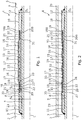
- Fig. 1 shows a cross-sectional view of an annular barrier 1 for providing zonal isolation in an annulus 2 downhole between a well tubular metal structure 3 and a wall 5 of a borehole 4 or another well tubular metal structure 3b, as shown in Fig. 2 .
- the annular barrier comprises a tubular metal part 7 configured to be mounted as part of the well tubular metal structure 3 and an expandable metal tubular 8 surrounding the tubular metal part forming an expandable space 9 there between.
- the expandable metal tubular is configured to be expanded in the well downhole from a first outer diameter D 1 to a second outer diameter D 2 (shown in Fig.
- the second circumferential groove 18 is arranged closer to the first end of the expandable metal tubular than the first circumferential grooves 15 with the sealing units 16.
- the annular barrier further comprises a split ring-shaped support element 21 element, which is arranged in the second circumferential groove for supporting the first groove part of the expandable metal tubular during expansion.
- the split ring-shaped support element 21 has a plurality of windings 22, so that when the expandable metal tubular is expanded from the first outer diameter D 1 to the second outer diameter D 2 , the split ring-shaped support element 21 partly unwinds and still supports the first groove part so as to minimise plastic strain in the first groove part during expansion.
- the thin first groove part would just bend radially outwards between the projections 33 thus weakening the first grove part significantly, so that the expandable metal tubular could not withstand as high a differential pressure.
- making the first groove part thicker would increase the expansion pressure.
- the split ring-shaped support element thus makes it possible to expand the expandable metal tubular with a relatively low expansion pressure around 400 bar and maintain a high collapse rating i.e. withstanding 700 bar differential pressure across the expandable metal tubular.
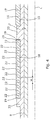
- the split ring-shaped support element occupies the second circumferential groove 18 along the longitudinal extension L in the unexpanded condition of the expandable metal tubular 8.
- the windings 22 of the split ring-shaped support element abut the circumferential edges 19 of the groove 18, as shown in Fig. 4 , and each winding 22 of the split ring-shaped support element 8 abuts each other.
- the groove 18 in the expandable metal tubular 8 has increased in length and the split ring-shaped support element 21 has partly unwinded and does no longer fill the groove.
- the split ring-shaped support element supports the first groove part of the expandable metal tubular, and part of the split ring-shaped support element may after expansion be squeezed in between the other well tubular metal structure 3b and the first groove part of the expandable metal tubular 8.
- the first groove part has its largest possible strength in the expanded condition and therefore is able to withstand the high pressure without collapsing.
- the annular barrier further comprises a third circumferential groove 18B near the second end.
- the third circumferential groove 18B is in the same way as the second circumferential groove 18 provided between two circumferential edges 19 provided on the outer face and defining a second groove part 20B of the expandable metal tubular between the circumferential edges.
- the third circumferential groove 18B is closer to the second end than the first circumferential grooves with the sealing units, and the third circumferential groove comprises another split ring-shaped support element 21 having a plurality of windings 22, so that when the expandable metal tubular is expanded from the first outer diameter D 1 to the second outer diameter D 2 , the split ring-shaped support element 21 partly unwinds.
- the split ring-shaped support element is arranged in the third circumferential groove for supporting the second groove part of the expandable metal tubular during expansion, so as to minimise plastic strain in the second groove part during expansion in the same way as for the first groove part.
- the split ring-shaped support element may be made of a metallic material, such as spring material, and like a helically coiled spring flex along the circumference.
- the split ring-shaped support element is preferably made of a material having a yield strength of at least 70 MPa, preferably at least 100 MPa, more preferably at least 200 MPa.
- the ring-shaped support element is preferably one split ring, but may also be divided into two matching helically wounded rings.
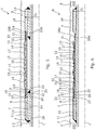
- the annular barrier 1 may have just one split ring-shaped support element arranged at the first end of the expandable metal tubular in the event that the annular barrier is only exposed to the high differential pressure from the first zone 101 and not the second zone 102 - after expansion of the annular barrier. Thus, the annular barrier 1 does not need to have a split ring-shaped support element in the second circumferential groove 18 as shown in Fig. 6 .
- the annular barrier further comprises an end sleeve 23 at the first end of the expandable metal tubular.
- the end sleeve 23 surrounds the expandable metal tubular in order to increase the collapse rating and is welded onto the outer face of the expandable metal tubular 8.
- the end sleeve 23 is made of a metal material having a higher yield strength than that of the expandable metal tubular.
- the end sleeve has a yield strength being twice as high as the yield strength of the expandable metal tubular.
- the expandable metal tubular may at the second end further comprise another end sleeve surrounding the expandable metal tubular in order to hinder free expansion of the second end and thus minimise the stress strain the metal.
- the first end having the end sleeve 23 has a more straight curve than the second end not comprising such end sleeve 23.
- the first end of the expandable metal tubular is thus prevented from free expansion and the end sleeve 23 having the higher yield strength forces the first end to straighten out, thereby decreasing the stress strain in the first end of the expandable metal tubular.
- the annular barrier may only have one end sleeve 23 at the first end in the event that the annular barrier is only exposed to the high differential pressure from the first zone 101 and not from the second zone 102 - after expansion of the annular barrier.
- the split ring-shaped retaining element has more than one winding so that when the expandable metal tubular is expanded from the first outer diameter D 1 to the second outer diameter D 2 , the split ring-shaped retaining element partly unwinds but still abuts the sealing element 17.
- the split ring-shaped retaining element ensures that the sealing element is maintained in the longitudinal extension of the expandable metal tubular even when it is being expanded, so that the sealing element retains its intended position and the sealing properties of the expandable metal tubular are enhanced.
- the sealing element may withstand a higher pressure on the side where the split ring-shaped retaining element is positioned, since the split ring-shaped retaining element functions as a back-up and support system for the sealing element.
- the ends of the expandable metal tubular have a thickness t e greater than the thickness t g (shown in Fig. 1 ) of the first and/or second groove part of the expandable metal tubular.
- the groove part is able to bridge between the ends of the expandable metal tubular having the larger thickness and smaller outer diameter and the part of the expandable metal tubular having the largest outer diameter in the expanded condition.
- the groove part partly conforms to the other well tubular metal structure and thus provides that the sealing units are arranged on a substantially straight part of the expandable metal tubular which forms the best basis for a perfect seal.
- the split ring-shaped support element may have at least 6 windings, preferably at least 10 windings as shown in Fig. 3 .
- an intermediate element 32 is arranged between the split ring-shaped support element and the groove part.
- the intermediate element is made of polytetrafluoroethylene (PTFE) or polymer.
- the annular barrier further comprises a tubular metal element 24 connecting the expandable metal tubular 8 with the tubular metal part 7.
- the tubular metal part is mounted as part of the well tubular metal structure by means of threaded connections 40.
- the tubular metal element 24 has an extension Lt in the longitudinal extension and a first end part 25 connected with the tubular metal part 7 and a second end part 26 connected with the expandable metal tubular 8. The first end part is arranged closer to the sealing units 16 along the longitudinal extension of the tubular metal part 7 than the second end part 26.
- the expandable metal tubular can be expanded without substantially thinning, as shown in Fig. 8 .
- the tubular metal element 24 is flexing, hence providing the sleeve with an additional flexing ability. If the expandable metal tubular 8 was only bent at its ends, the bend would unbend, which would generate an extremely high stress in the connection between the expandable metal tubular and the tubular metal part, which may result in a crack in the connection to the tubular metal part and hence a leaking annular barrier.
- the tubular metal part has an opening 28 fluidly connected with the expandable space for letting fluid from within the tubular metal part to the expandable space to expand the expandable metal tubular.
- the opening may be arranged opposite the space 9, as shown in Figs. 7 and 8 , or be arranged near one of the ends of the expandable metal tubular 8 and connected with the expandable space via a valve system.
- the valve system comprises a valve for shifting between fluid communication between the space and the opening and fluid communication between the space and the annulus for equalising the pressure there between after expansion.
- the split ring-shaped retaining element 31 is preferably made of metal material having a yield strength of at least 70 MPa, preferably at least 100 MPa, more preferably at least 200 MPa.
- the split ring-shaped retaining element 31 is made of a spring material and unwinds by less than one winding when the expandable metal tubular 8 is expanded from the first outer diameter D 1 to the second outer diameter D 2 .
- the split ring-shaped retaining element 31 has a width w in the longitudinal extension, and the width being substantially the same in the first outer diameter D 1 and the second outer diameter D 2 of the expandable metal tubular.
- the sealing unit 16 has two split ring-shaped retaining elements 31 which together with the sealing element 17 fill the first circumferential groove 15 from edge 19 to edge 33.
- the split ring-shaped retaining element 31 has a plurality of windings and in Figs. 8 and 9 , the split ring-shaped retaining element 31 has three windings.
- the expandable metal tubular 8 has a first thickness T 1 in the first circumferential groove between a first and a second circumferential edges 19 and a second thickness T 2 in adjacent areas, where the first thickness T 1 being smaller than the second thickness T 2 .
- the circumferential edges 19 are extending in a radial extension in relation to the expandable metal tubular, where radial extension being perpendicular to the longitudinal extension L of the expandable metal tubular.
- the grooves are thus provided between projections 33 of the expandable metal tubular.
- an intermediate element 32 is arranged between the split ring-shaped retaining element 31 and the sealing element 17.
- the intermediate element is made of polytetrafluoroethylene (PTFE) or polymer.
- the split ring-shaped retaining element 31 and the intermediate element 32 are arranged in an abutting manner to the sealing element, so that at least one of the split ring-shaped retaining element and the intermediate element abuts the sealing element.
- the sealing element is made of an elastomer, rubber, polytetrafluoroethylene (PTFE) or another polymer.
- the intermediate element 32 may be made of a flexible material and is adapted to maintain the split ring-shaped retaining element 31 in position and function as protection and support of the sealing element 17.
- the split ring-shaped retaining element 31, the intermediate element 31 and the sealing element 17 are placed in the groove 15 between the first and second circumferential edges 19.
- the windings of the split ring-shaped retaining elements 31 have a round cross-section and partly overlap the intermediate elements 32.
- the split ring-shaped retaining element 7 when the expandable metal tubular is expanded by 30%, the split ring-shaped retaining element 7 is unwound by approximately 30% of the circumference of the split ring-shaped retaining element 7, and thus the split ring-shaped retaining element 7 decreases its number of windings so that it is still capable of closing the gaps in the longitudinal extension, whereby the sealing element, the split ring-shaped retaining elements and the intermediate elements (if present) fill out the gap between the first and second circumferential edges 3, 4.
- the split ring-shaped support elements 21 may have a round cross-section.
- the split ring-shaped support element in one groove may be comprised of several separate parts, where each part has a plurality of windings. By being comprised of several parts, the split ring-shaped support element can more easily and quickly unwind without limiting the support effect and without increasing the plastic strain of the expandable metal tubular.
- the downhole completion 100 comprises the well tubular metal structure 3 and the annular barrier 1, where the tubular metal part of the annular barriers is mounted as part of the well tubular metal structure.
- the annular barrier 1 further comprises a shear pin assembly 37 fluidly connecting the opening 28 in the tubular metal part 7 and the expandable space 9 in order to allow expansion fluid within the well tubular metal structure 3 to expand the expandable metal tubular 8.
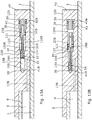
- the shear pin assembly 37 has a first position (shown in Fig. 13A ) in which expansion fluid is allowed to flow into the space 9 and a second position (shown in Fig. 13B ) in which the opening 28 is blocked, preventing expansion fluid from entering the space 9.
- the annular barrier 1 further comprises an anti-collapsing unit 111 comprising an element 201 (as shown in Fig. 14 ) movable at least between a first position and a second position.
- the anti-collapsing unit has a first inlet 25B which is in fluid communication with the first zone, and a second inlet 26B which is in fluid communication with the second zone, and the anti-collapsing unit having an outlet 27 which is in fluid communication with the space 9.
- the first inlet is in fluid communication with the outlet, equalising the first pressure of the first zone 101 with the space pressure in the space 9
- the second inlet is in fluid communication with the outlet, equalising the second pressure of the second zone with the space pressure.
- the shear pin assembly 37 has a port A receiving fluid from an inside of the well tubular structure 3 through the screen 44.
- the port A is fluidly connected with a port D during expansion, causing the expansion fluid within the well tubular metal structure 3 to expand the expandable metal tubular 8.
- the pressure builds up and a shear pin or disc within the shear pin assembly shears closing the fluid connection from port A and opening 28 (as shown in Fig.
- the shear pin assembly shown in Fig. 13A and 13B comprises a first bore part 19B having a first inner diameter and a second bore part 120B having an inner diameter which is larger than that of the first bore part.
- the opening 28 and a second opening 17B are arranged in the first bore part 19B and are displaced along the bore extension.
- the annular barrier 1 further comprises a piston 121 arranged in the bore 18B, the piston comprising a first piston part 22B having an outer diameter substantially corresponding to the inner diameter of the first bore part 19B, and comprising a second piston part 23B having an outer diameter substantially corresponding to the inner diameter of the second bore part 120B.
- the annular barrier 1 further comprises a rupture element 24B preventing movement of the piston 121 until a predetermined pressure in the bore 18B is reached.
- the strength of the rupture element is set based on a predetermined pressure acting on the areas of the ends of the piston, and thus, the difference in outer diameters results in a movement of the piston when the pressure exceeds the predetermined pressure.
- the piston 121 comprises a fluid channel 125 being a through bore providing fluid communication between the first and second bore parts 19B, 120B.
- the rupture element 24B is a shear pin but may also be a disc.
- the shear pin is intact and extends through the piston and the inserts 43, and in Fig. 13B , the shear pin is sheared and the piston is allowed to move, and the inserts 43 have moved towards the centre of the bore 18B.
- the rupture element 24B is selected based on the expansion pressure so as to break at a pressure higher than the expansion pressure but lower than the pressure rupturing the expandable metal tubular or jeopardising the function of other completion components downhole.
- the bore 18B and the piston 121 may be arranged in a connection part connecting the first ends to the tubular metal part.
- the annular barrier 1 comprises a locking element 38 which is arranged around the second piston part 23B.
- the bore further comprises a third opening 137 in the second bore part 120B, which third opening is in fluid communication with the space 9 and the annulus/borehole 2.
- the third opening 137 may be arranged in fluid communication with a shuttle valve, as shown in Fig. 14 , in such a way that the shuttle valve is arranged between the third opening and the annulus, thus providing fluid communication between the space 9 and the annulus.
- the shuttle valve provides, in a first position, fluid communication between the space 9 and the first zone 101 of the annulus, and in a second position, the shuttle valve provides fluid communication between the annular space and the second zone 102 of the annulus.
- the expandable metal tubular may be made from one tubular metal blank, wherein the blank may be made by centrifugal casting or spin casting. Furthermore, the first and second circumferential edges 19 may be provided by machining the blank.
- Fig. 11 shows a cross-sectional view of annular barriers 1 which have been expanded in an annulus 2 between the well tubular structure 3 and an inside face of the borehole 4.
- the annular barrier 1 provides zone isolation between a first zone 101 and a second zone 102 of the borehole.
- the annular barrier 1 has a longitudinal extension which coincides with the longitudinal extension of the casing/well tubular structure 3.
- the annular barrier 1 comprises a tubular metal part 7, which may be a separate tubular part or a casing part for mounting a part of the well tubular structure 3.
- the annular barrier 1 comprises the expandable metal tubular 1 which surrounds the tubular metal part, and each end of the expandable metal tubular 1 may be connected with the tubular metal part by means of connection parts.
- the expandable metal tubular 1 and the tubular metal part 7 enclose an annular barrier space 9, and an expansion opening 28 is provided in the tubular metal part, through which fluid may enter the space 9 in order to expand the expandable metal tubular 1 as shown in Figs. 3 and 8 .
- the expandable metal tubular 1 is expanded until the sealing elements 16 or the projections 33 abut the inner face of the borehole 4, so that fluid is prevented from flowing freely from the first zone 101 to the second zone 102.
- annular barriers 1 are often used to isolate a production zone 400.
- a fracturing valve or inflow valve section 120 also called the frac port or inflow/production valve, is arranged in between the annular barriers 1, so that when the annular barriers 1 have been expanded, the frac port or valve 120 is opened and fluid is let into the formation for creating fractures in the formation to ease the flow of hydrocarbon-containing fluid, such as oil, into the well tubular structure 3.
- the fracturing valve or inflow section 120 may also comprise an inlet section which may be the same as the frac port.
- a screen may be arranged so that the fluid is filtered before flowing into the casing.
- the annular barrier further comprises a intermediate sleeve (not shown) arranged in between the expandable metal tubular 1 and the tubular metal part 7.
- the intermediate sleeve is connected with the tubular metal part 7 and the expandable metal tubular 1, thus dividing the space 9 into a first space section and a second space section.
- the intermediate sleeve is squeezed in between the tubular metal part and the expandable metal tubular.
- the intermediate sleeve may also be connected with the tubular metal part in another manner, such as crimped onto the tubular part.
- the expandable metal tubular has an aperture providing fluid communication between the first or the second zone and one of the space sections, thus equalising the pressure between the space and that zone.
- the pressure in one of the zones in which hydraulic fracturing is performed is increasing, and in order to prevent the expandable metal tubular from collapsing, the fluid is let in through the aperture and into the first space section.
- the intermediate sleeve moves towards the tubular metal part, thus yielding to the increased pressure in the first space section, and the first space section increases until the pressure equalises or the intermediate sleeve abuts the tubular metal part.
- the expandable metal tubular part may also be crimped onto the tubular part, or, if the annular barrier comprises a sleeve, crimped onto the sleeve at its ends.
- the sleeve is flexible and made of metal or a polymer, such as elastomer.
- the tubular blank may be made of any kind of metal, such as iron, steel or stainless steel, or more ductile materials, such as copper, aluminium, lead, tin, nickel, or a combination thereof.
- fluid or well fluid any kind of fluid that may be present in oil or gas wells downhole, such as natural gas, oil, oil mud, crude oil, water, etc.
- gas is meant any kind of gas composition present in a well, completion, or open hole
- oil is meant any kind of oil composition, such as crude oil, an oil-containing fluid, etc.
- Gas, oil, and water fluids may thus all comprise other elements or substances than gas, oil, and/or water, respectively.
- a casing or well tubular metal structure is meant any kind of pipe, tubing, tubular, liner, string etc. used downhole in relation to oil or natural gas production.
Landscapes
- Life Sciences & Earth Sciences (AREA)
- Engineering & Computer Science (AREA)
- Geology (AREA)
- Mining & Mineral Resources (AREA)
- Physics & Mathematics (AREA)
- Environmental & Geological Engineering (AREA)
- Fluid Mechanics (AREA)
- General Life Sciences & Earth Sciences (AREA)
- Geochemistry & Mineralogy (AREA)
- Gasket Seals (AREA)
Priority Applications (3)
| Application Number | Priority Date | Filing Date | Title |
|---|---|---|---|
| EP18212358.8A EP3667014A1 (de) | 2018-12-13 | 2018-12-13 | Ringförmige barriere |
| US16/691,930 US20200165892A1 (en) | 2018-11-23 | 2019-11-22 | Annular barrier |
| PCT/EP2019/082269 WO2020104671A1 (en) | 2018-11-23 | 2019-11-22 | An annular barrier |
Applications Claiming Priority (1)
| Application Number | Priority Date | Filing Date | Title |
|---|---|---|---|
| EP18212358.8A EP3667014A1 (de) | 2018-12-13 | 2018-12-13 | Ringförmige barriere |
Publications (1)
| Publication Number | Publication Date |
|---|---|
| EP3667014A1 true EP3667014A1 (de) | 2020-06-17 |
Family
ID=64665449
Family Applications (1)
| Application Number | Title | Priority Date | Filing Date |
|---|---|---|---|
| EP18212358.8A Withdrawn EP3667014A1 (de) | 2018-11-23 | 2018-12-13 | Ringförmige barriere |
Country Status (1)
| Country | Link |
|---|---|
| EP (1) | EP3667014A1 (de) |
Cited By (4)
| Publication number | Priority date | Publication date | Assignee | Title |
|---|---|---|---|---|
| CN114382455A (zh) * | 2022-01-12 | 2022-04-22 | 北京科源博慧技术发展有限公司 | 一种页岩气水平井重复压裂方法 |
| US20240229614A1 (en) * | 2023-01-10 | 2024-07-11 | Halliburton Energy Services, Inc. | Expandable Liner Hanger With Robust Slips For Downhole Conditions With High Pressure Conditions |
| US12252961B2 (en) | 2022-05-23 | 2025-03-18 | Halliburton Energy Services, Inc. | Expandable liner hanger assembly having one or more hardened sections |
| US12398624B2 (en) | 2023-07-11 | 2025-08-26 | Halliburton Energy Services, Inc. | Self-energizing seal for expandable liner hanger |
Citations (5)
| Publication number | Priority date | Publication date | Assignee | Title |
|---|---|---|---|---|
| EP2644821A1 (de) * | 2012-03-30 | 2013-10-02 | Welltec A/S | Ringförmige Abgrenzung mit flexiblem Anschluss |
| EP2789792A1 (de) * | 2013-04-12 | 2014-10-15 | Welltec A/S | Erweiterbares Bohrlochrohr |
| EP3106606A1 (de) * | 2015-06-19 | 2016-12-21 | Welltec A/S | Expandierbares bohrlochmetallrohr |
| EP3216976A1 (de) * | 2010-10-07 | 2017-09-13 | Welltec A/S | Ringförmige barriere |
| EP3299575A2 (de) * | 2018-01-31 | 2018-03-28 | Welltec A/S | Bohrlochabschlusssystem und verfahren |
-
2018
- 2018-12-13 EP EP18212358.8A patent/EP3667014A1/de not_active Withdrawn
Patent Citations (5)
| Publication number | Priority date | Publication date | Assignee | Title |
|---|---|---|---|---|
| EP3216976A1 (de) * | 2010-10-07 | 2017-09-13 | Welltec A/S | Ringförmige barriere |
| EP2644821A1 (de) * | 2012-03-30 | 2013-10-02 | Welltec A/S | Ringförmige Abgrenzung mit flexiblem Anschluss |
| EP2789792A1 (de) * | 2013-04-12 | 2014-10-15 | Welltec A/S | Erweiterbares Bohrlochrohr |
| EP3106606A1 (de) * | 2015-06-19 | 2016-12-21 | Welltec A/S | Expandierbares bohrlochmetallrohr |
| EP3299575A2 (de) * | 2018-01-31 | 2018-03-28 | Welltec A/S | Bohrlochabschlusssystem und verfahren |
Cited By (6)
| Publication number | Priority date | Publication date | Assignee | Title |
|---|---|---|---|---|
| CN114382455A (zh) * | 2022-01-12 | 2022-04-22 | 北京科源博慧技术发展有限公司 | 一种页岩气水平井重复压裂方法 |
| CN114382455B (zh) * | 2022-01-12 | 2023-10-03 | 北京科源博慧技术发展有限公司 | 一种页岩气水平井重复压裂方法 |
| US12252961B2 (en) | 2022-05-23 | 2025-03-18 | Halliburton Energy Services, Inc. | Expandable liner hanger assembly having one or more hardened sections |
| US20240229614A1 (en) * | 2023-01-10 | 2024-07-11 | Halliburton Energy Services, Inc. | Expandable Liner Hanger With Robust Slips For Downhole Conditions With High Pressure Conditions |
| US12497866B2 (en) * | 2023-01-10 | 2025-12-16 | Halliburton Energy Services, Inc. | Expandable liner hanger with robust slips for downhole conditions with high pressure conditions |
| US12398624B2 (en) | 2023-07-11 | 2025-08-26 | Halliburton Energy Services, Inc. | Self-energizing seal for expandable liner hanger |
Similar Documents
| Publication | Publication Date | Title |
|---|---|---|
| EP2984282B1 (de) | Erweiterbares bohrlochrohr | |
| US20200165892A1 (en) | Annular barrier | |
| US10494910B2 (en) | Active external casing packer (ECP) for frac operations in oil and gas wells | |
| EP3667014A1 (de) | Ringförmige barriere | |
| US20110048740A1 (en) | Securing a composite bridge plug | |
| AU2019317982B2 (en) | An annular barrier system | |
| WO2009061768A2 (en) | Self-energizing annular seal | |
| EP3584403A1 (de) | Ringförmige barriere | |
| WO2023275277A1 (en) | Annular barrier | |
| AU2019394664B2 (en) | Annular barrier with valve unit | |
| CA2932896C (en) | Expansion cone for downhole tool | |
| AU2016424204B2 (en) | High expansion metal back-up ring for packers and bridge plugs |
Legal Events
| Date | Code | Title | Description |
|---|---|---|---|
| PUAI | Public reference made under article 153(3) epc to a published international application that has entered the european phase |
Free format text: ORIGINAL CODE: 0009012 |
|
| STAA | Information on the status of an ep patent application or granted ep patent |
Free format text: STATUS: THE APPLICATION HAS BEEN PUBLISHED |
|
| AK | Designated contracting states |
Kind code of ref document: A1 Designated state(s): AL AT BE BG CH CY CZ DE DK EE ES FI FR GB GR HR HU IE IS IT LI LT LU LV MC MK MT NL NO PL PT RO RS SE SI SK SM TR |
|
| AX | Request for extension of the european patent |
Extension state: BA ME |
|
| STAA | Information on the status of an ep patent application or granted ep patent |
Free format text: STATUS: THE APPLICATION IS DEEMED TO BE WITHDRAWN |
|
| 18D | Application deemed to be withdrawn |
Effective date: 20201218 |