EP3299727A1 - Covering fixture for a pit ventilator and pit ventilator inlet unit with a covering fixture - Google Patents
Covering fixture for a pit ventilator and pit ventilator inlet unit with a covering fixture Download PDFInfo
- Publication number
- EP3299727A1 EP3299727A1 EP17188177.4A EP17188177A EP3299727A1 EP 3299727 A1 EP3299727 A1 EP 3299727A1 EP 17188177 A EP17188177 A EP 17188177A EP 3299727 A1 EP3299727 A1 EP 3299727A1
- Authority
- EP
- European Patent Office
- Prior art keywords
- opening
- filter
- trough
- lid
- cover
- Prior art date
- Legal status (The legal status is an assumption and is not a legal conclusion. Google has not performed a legal analysis and makes no representation as to the accuracy of the status listed.)
- Withdrawn
Links
Images


Classifications
-
- F—MECHANICAL ENGINEERING; LIGHTING; HEATING; WEAPONS; BLASTING
- F24—HEATING; RANGES; VENTILATING
- F24C—DOMESTIC STOVES OR RANGES ; DETAILS OF DOMESTIC STOVES OR RANGES, OF GENERAL APPLICATION
- F24C15/00—Details
- F24C15/20—Removing cooking fumes
- F24C15/2042—Devices for removing cooking fumes structurally associated with a cooking range e.g. downdraft
Definitions
- the approach presented here relates to a cover device for a tray ventilator and a tray ventilator inlet unit with a cover device.
- a bowl ventilator When it is switched on, a bowl ventilator should suck in as much vapor as possible through a gap that is as large as possible and be closed by a lid when not in use and visually inconspicuous in the living environment of the kitchen. If the lid of the bowl ventilator needs to be removed / released from the bowl ventilator during operation of the bowl ventilator, it may be lost.
- the DE 10 2009 025 038 A1 describes a device for the withdrawal of cooking fumes in vertically below a cooking field level direction with a one or more parts, removable lid-shaped closing device for reversibly closing the inlet opening of the cooking fume inlet device.
- the approach presented here has the object to provide an improved cover device for a well ventilator and an improved Muldenllibraryereinlassech with a cover.
- a cover device for a tray ventilator has at least one lid and a filter device.
- the lid is shaped to be received by a trough opening of a trough of the tray fan to at least partially close the tray opening.
- the lid may also be shaped to completely shoot the well opening in the received state to cover and protect components of the well ventilator disposed in the well while the well ventilator is not operating.
- the filter device is durable with the lid, d. H. insoluble, connected.
- Dump ventilators are designed to suck in vapors, which may be formed, for example, during cooking in the region of a hob, downwards through a well opening in a depression of the well ventilator.
- the trough opening is usually in the area of Hob, for example, embedded in a center of the hob or arranged in the region of an edge of the hob.
- a filter device is usually formed as a frame with a filter, but the filter device can also be formed only as the filter.
- the filter device is often arranged in a low-lying region of the trough from the trough opening.
- the filter is usually formed to filter fat from the vapor, but may also be shaped to protect against a flame of a gas burner.
- the filter device can be arranged in the region of the cover and thus, for example, removal of the cover from a trough fan inlet unit of the trough ventilator or from the trough opening during operation of the trough ventilator is unnecessary.
- lid and filter device of the tray fan always remain one unit and no parts of the tray fan are lost.
- the filter device For receiving a filter unit that can be positioned deep in the trough, the filter device can have a filter frame and the filter unit that is received by the filter frame, wherein the filter frame can be arranged between the lid and the filter unit and can be shaped as a grease filter.
- the filter rack can serve as a connector between the lid and the filter unit.
- the filter unit can be arranged transversely to the lid.
- the covering device may have an opening device which is designed to enable the covering device to be moved out of the depression opening mechanically and / or magnetically and / or motorily in a state received in the depression opening.
- the filter device can be at least partially extended out of the well opening in the direction of the hob or pulled out to allow withdrawal of Wrasens through lateral longitudinal sides of the filter frame into the trough.
- the cover can be securely held in the well opening in the well opening in the well opening in the well opening in the well opening, if in the region of the well also a magnet is arranged.
- slipping of the lid can be counteracted by light touches.
- the filter device has at least one protective element, for example a cover plate or a wire mesh, this can prevent at least one gas and / or one gas flame from flowing into the covering device.
- a protective element for example a cover plate or a wire mesh
- the protective element on two of the longitudinal sides of the filter frame on an inner side and / or an outer side of the longitudinal sides arranged.
- the wire mesh can also be arranged on a filter device arranged in the region of the lid, or the filter device itself can be at least partially shaped as the wire mesh.
- the cover may have at least one passage opening, which may be formed to allow passage of vapor into the recess in the recess opening in the cavity opening.
- the lid can remain accommodated during operation of the hollow ventilator in the well ventilator opening.
- At least one fire-resistant material can be arranged in the passage opening.
- Fireproofing is to be understood as meaning a nonflammable material which has at least one fire resistance of a period of time defined within a tolerance range. This period of time may be, for example, at least 10 minutes.
- the refractory material may be a wire mesh formed to prevent entry of at least one gas and / or gas flame from a gas burner into the trough.
- the filter device may be at least partially received in the lid.
- the filter device can be arranged flush with a surrounding the trough opening frame member of the trough in the trough opening and span it at least partially.
- the vapors can thus be filtered directly on entering the trough opening and the lid, even if the filter device according to one embodiment advantageously formed wras trimelle remain during the operation of the trough blower in the trough opening remain.
- the lid When the lid is shaped to be deployable or hinged at least partially transverse to the well opening from the well, the lid in the erected condition between the well opening and a gas burner can serve as a flow barrier for at least one gas flame to prevent the lid Gas flame jumps into the trough or gas enters the trough.
- the cover device may also be shaped to be displaceable in the well opening in the well opening in the well opening.
- the covering device can be displaced longitudinally and / or transversely, for example, from the side.
- the trough opening can be partially opened by moving and enter the vapors during operation of the trough blower in the trough, while a large part of the trough opening can remain closed.
- a tray fan inlet unit for a tray ventilator has at least the well described and one of the presented cover devices, wherein the lid of the cover device is received in the well opening of the tray.
- a trough fan inlet unit presented here can serve as a substitute for known trough fan inlet units, the presented trough fan inlet unit advantageously realizing the already presented advantages of the cover device.
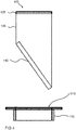
- FIG. 1 shows a side cross-section of a well ventilator unit 100 for a well ventilator with a cover 105 according to an embodiment.
- the trough fan inlet unit 100 has at least one trough 110 with a trough opening 115 and the covering device 105.
- the trough 110 has, around the trough opening 115, a frame element 120 which surrounds the trough opening 115 adapted to be arranged or adjacent to a hob of a hearth.
- the covering device 105 is accommodated in the depression opening 115 such that a cover 125 of the covering device 105 closes the depression opening 115.
- the covering device 105 has a filter device 130.
- the filter device 130 is permanently connected to the lid 125.
- the filter device 130 has a filter frame 135 and a filter unit 140.
- the filter unit 140 is received by the filter rack 135, which is arranged between the lid 115 and the filter unit 140.
- the filter unit 140 is arranged transversely to the lid 125.
- the presented here Muldenllibraryereinlassech 100 can also be referred to as a tray ventilator with filter element incl.
- Cover since the cover is formed in the form of the lid 125 in one piece with the filter element in the form of the filter device 130.
- the lid 125 of the device in the form of the well filter device 105 is according to this embodiment structurally a unit with the filter device 130.
- a mechanical, z. B. a push-pull mechanism, and / or magnetic and / or motor opening mechanism in the cover 105 in the form of an opening device z. B.
- the lid 125 is mechanically and / or magnetically and / or motor-opened.
- the unit of cover 125 and filter device 130 moves vertically, parallel to the trough 110 and to the built-in housing in the form of the housing member 120 by a certain amount, for. B. 20 mm in height.
- a fan can now be started, whereby Wrasen laterally, ie left and right of the projecting beyond the housing member 120 part of the filter frame 135, is discharged. If the user desires a larger discharge surface or opening, he can achieve this by simply pulling up the lid 125. When the lid 125 is completely removed, the filter unit 140 associated with the lid 125 can be removed and cleaned.
- the lid 125 is in this embodiment handle of the filter rack 135 and the filter unit 140 and the filter rack 135 holds the filter unit 140.
- the essential object of the approach here is less a generation of a vertically or horizontally oriented opening for removing the Wrasens, but rather a question, which relates to a simplified handling of the exchangeable filter unit 140 and a handling of the lid 125.
- the user does not want to see the filter device 130 due to a possible contamination during operation and reluctant in the removal of the filter device 130 for fear of injury or due to handling outside the field of view the trough opening 115 engage. Furthermore, the user does not want to touch the filter device 130 to be cleaned for reasons of hygiene.
- the approach further provides through the opening means a simple but staged movement of the lid 125, a show effect, and a fixed storage location for the lid 125 when using the fan.
- the approach provides a solution to all these questions:
- the lid 125 forms a unit with the filter rack 135.
- the filter unit 140 is inserted in the filter rack 135 and the lid 125 is attached as a handle on the filter rack 135.
- the lid 125 as a handle serves to make the unit in the form of the cover 105, for example, for cleaning or filter replacement, easy to remove.
- the cover device 105 is removed, the filter unit 140 is easily accessible outside the trough opening 115. Possibly.
- the entire cover device 105, including the filter device 140 which may be a grease filter, can be placed in a dishwasher.
- the vertical process between a rest position and an operating position can be solved differently, namely purely motor or purely mechanically or by mixing.
- An at least two-stage extension between a supply / operating position shown here and an in Fig. 3 and 7 shown removal position is possible.
- a trigger for the adjustment can be initiated manually, for example by pressing a button or Push-To-Open, or automatically done with a switch on the fan or the steam exhaust hood.
- a use of an in Fig. 5 Locking elements shown is possible on both longitudinal sides of the filter rack 135, so as to allow operation of a well ventilator with the Muldenlcertainereinlassech 100 next to a gas hob, wherein the blocking element prevents a gas flame or unburned gas is sucked into the cover 105.
- the filter in the form of the filter unit 140 is accordingly easy and convenient to remove from the well ventilator inlet unit 100.
- the lid 125 does not have to be removed separately.
- the opening mechanism serves an enthusiasm factor and an aesthetic appearance of the covering device 105.
- exhaust hoods often have an open suction duct in the form of the trough in the cooking surface during an active extraction.
- the trough opening is covered with a cover, for example made of glass ceramic.
- the cover in the form of the lid 125 may be flat for shielding the gas hob only to cover the suction channel and only of glass ceramic.
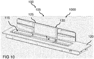
- the lid 125 can also as in Figure 10 described to be set up.
- the cover 105 is a permanent cover with integrated filter device 130 of wire mesh stable design, z. B. welded in the rolling process.
- a sound-insulating property can also be set.
- this approach provides flame protection against the suction of at least one flame a positioned next to the trough opening gas burner in the gas hob.
- the lid 125 can not fall into the trough. The insertion of the cover 105 in the well opening is simple, longitudinally and transversely from the side pushed.
- a permanent wire mesh cover described here provides flame protection and reduces sound noise through the use of wire mesh instead of glass ceramic.
- the cover is more customer-friendly than known covers, it does not need to be removed and placed on the suction each time. Furthermore, it offers flame-retardant properties, or a flame arrester and reduces with selected dimensioning fan noise of the suction opening or trough opening.
- FIGS. 9 to 14 show a flush design of the cover 105.
- the cover 105 is at least partially designed as flush with the lid 125 designed filter device 130.
- the filter device 130 which can also be referred to as a filter element, serve as a grease filter or alternatively as a flame filter.
- the at least partially formed on the lid 125 fabric, knitted or knitted fabric in the form of the filter device 130 may serve as a grease filter.
- a covering device 105 can be removed after intensive use and cleaned in the dishwasher.
- the trough opening with a z. B. closed mesh fabric this can according to a in Fig. 14 illustrated alternative embodiment to prevent a flame passage.
- the fabric is preferably made of a fire-resistant material and so wide that extremely little, preferably no fat can attach to it. This is achieved because the cold metal fabric deprives the flame of energy and a passing flame goes out. The flame, if it reaches the net or tissue, would cling to it and rise to the top, but not pass through.
- This embodiment also allows a closed trough opening when using the tray ventilator, thereby preventing objects such as spoons, knives and / or foods, such as or noodles, from falling into the trough.
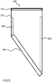
- FIG. 10 shows a perspective side view of a well ventilator inlet unit 100 according to an embodiment. This can be one of the basis of one of FIGS. 1 . 3 . 4 . 6 . 7 or 8th described with the difference that the lid 125 can be set up in a set-up 1000, in which the lid 125 itself forms the filter device 130. The lid 125 has been folded in the set-up position 1000 shown here transversely to the trough opening 115 of the trough 110 away.
- a capping device 105 presented here can be placed between the well opening 105 and the gas burner and thus create a flow barrier for the flame. Wrasen from a much higher garnish, z. B. from a pot or pan, can easily flow over the established cover in the trough opening 115.
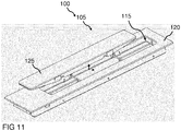
- FIG. 11 shows a perspective view of a Muldenlalthoughereinlassech 100 according to an embodiment. These may be the ones based on Fig. 10 described with the difference that the lid 125 is not placed, but in the trough opening 115 has been moved longitudinally and transversely from the side. The trough opening 115 is partially closed in this position of the lid 125.
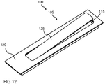
- FIG. 12 shows a perspective view of a Muldenlrangeereinlassech 100 according to an embodiment. These may be the ones based on Fig. 11 described with the difference that the cover has been moved so that it almost completely closes the trough opening 115.
- FIG. 13 shows a perspective view of a well opening 115 of a Muldenlrangeereinlassech. It may be one of the well openings 115 of the basis of one of FIGS. 10 to 12 act described Muldenlalthoughereinlassechen.
- Two T-shaped members 1300 extend from two ends of the trough opening 115 toward a center of the trough opening 115, the shorter side of the T-shaped members 1300 facing the center of the trough opening 115 and arranged transversely to a main extension length of the trough opening 115.
- the T-shaped members 1300 are formed to be one of the basis of the FIGS. 9 to 12 record and keep in the trough opening 115, without that this can fall into the trough.
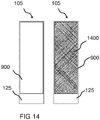
- FIG. 14 shows a plan view of a cover 105 according to an embodiment. These may be the ones based on Fig. 9 described covering device 105, with the difference that the covering device 105 instead of the filter device in the through-hole 900, the fire-resistant material 1400 and the filter device as in the FIGS. 1 to 8 is arranged on the cover 105.
- a cover device 105 with a fabric cover in the form of fire-resistant material 1400 Is shown in Fig. 14 a cover device 105 with a fabric cover in the form of fire-resistant material 1400.
- Filter devices of trough blowers are usually in the bottom of a trough in the trough blower and when not in use by the lid 125 o. covered.
- the well opening of the well ventilator is often open, the user can look into the well and, if necessary, parts such as cooking utensils or food can fall into the well.
- the filter means can only be removed unergonomically through the small trough opening or down from the trough blower.
- the tray ventilator is optically closed at the top by an air-permeable, fabric-like cover in the form of the covering device 105 with the refractory material 1400.
- the covering device 105 advantageously does not have to be removed from the depression opening during use of the depression ventilator.
- the surface of the fire-resistant material 1400 is so permeable to air that the vapor penetrates the through-opening 900 of the lid 125 without great losses and is detected below in the trough blower of the conventional filter device.
- the filter device can be removed after removal of the lid 125 with the refractory material 1400 from the trough opening upwards.
- the well ventilator is as in Fig. 9 above in the region of the trough opening by an air-permeable, filter-like cover, for example of a fabric, for. B. metal and / or a perforated or microperforated surface of metal, plastic and / or glass optically closed, the cover also need not be removed when using the hollow fan.
- the fabric meets the functional requirements of the filter device so that the filter device is no longer needed at the bottom of the tray ventilator. As a result, the entire device height of the tray ventilator could be reduced enormously.
- the filter device is always covering on the trough opening, in the active and inactive state of the trough blower, and after each use easy z. B. be cleaned in the dishwasher.
- the cover 105 is a further advantage that the Muldenllibraryereinlassiki saves by the flat-lying filter device much height, otherwise by a in the FIGS. 1 to 8 shown tilted filter unit inside the trough arises.
- the cover is flush or almost flush with adjacent devices such as hobs, CombiSet devices or a worktop.
- the cover 105 is easy to remove to clean the bowl ventilator inside.
- the refractory material 1400 or the filter device in the through-opening 900 can consist of different materials, eg. B. from textile, plastic, stainless steel, other composites, eg. As fiberglass composite, and may be made in one piece / single-layer or multi-part / multi-layered.
- FIG. 15 11 shows a plan view of a fire-resistant material 1400 and a cross-section of a fire-resistant material 1400 according to an exemplary embodiment. This may be the in Fig. 14 described fire-resistant material 1400 act.
Landscapes
- Engineering & Computer Science (AREA)
- Chemical & Material Sciences (AREA)
- Combustion & Propulsion (AREA)
- Mechanical Engineering (AREA)
- General Engineering & Computer Science (AREA)
- Filtering Of Dispersed Particles In Gases (AREA)
Abstract
Der hier vorgestellte Ansatz betrifft eine Abdeckvorrichtung (105) für einen Muldenlüfter. Die Abdeckvorrichtung (105) weist zumindest einen Deckel (125) und eine Filtereinrichtung (130) auf. Der Deckel (125) ist dazu ausgeformt, um von einer Muldenöffnung einer Mulde (110) des Muldenlüfters aufgenommen zu werden, um die Muldenöffnung zumindest teilweise zu verschließen. Die Filtereinrichtung (130) ist mit dem Deckel (125) dauerhaft verbunden.The approach presented here relates to a cover device (105) for a tray ventilator. The cover device (105) has at least one cover (125) and a filter device (130). The lid (125) is shaped to be received by a trough opening of a trough (110) of the tray fan to at least partially close the tray opening. The filter device (130) is permanently connected to the cover (125).
Description
Der hier vorgestellte Ansatz betrifft eine Abdeckvorrichtung für einen Muldenlüfter und eine Muldenlüftereinlasseinheit mit einer Abdeckvorrichtung.The approach presented here relates to a cover device for a tray ventilator and a tray ventilator inlet unit with a cover device.
Ein Muldenlüfter soll im eingeschalteten Zustand möglichst viel Wrasen durch einen möglichst großen Spalt einsaugen und sich bei Nichtgebrauch durch einen Deckel verschlossen und optisch unauffällig in das Wohnumfeld Küche integrieren bzw. verschlossen sein. Wenn der Deckel des Muldenlüfters während des Betriebs des Muldenlüfters von dem Muldenlüfter abgenommen/gelöst werden muss, kann er verloren gehen.When it is switched on, a bowl ventilator should suck in as much vapor as possible through a gap that is as large as possible and be closed by a lid when not in use and visually inconspicuous in the living environment of the kitchen. If the lid of the bowl ventilator needs to be removed / released from the bowl ventilator during operation of the bowl ventilator, it may be lost.
Die
Dem hier vorgestellten Ansatz liegt die Aufgabe zugrunde, eine verbesserte Abdeckvorrichtung für einen Muldenlüfter sowie eine verbesserte Muldenlüftereinlasseinheit mit einer Abdeckvorrichtung zu schaffen.The approach presented here has the object to provide an improved cover device for a well ventilator and an improved Muldenlüftereinlasseinheit with a cover.
Erfindungsgemäß wird diese Aufgabe durch eine Abdeckvorrichtung für einen Muldenlüfter und schließlich eine Muldenlüftereinlasseinheit mit einer Abdeckvorrichtung mit den Merkmalen der Hauptansprüche gelöst. Vorteilhafte Ausgestaltungen und Weiterbildungen des Ansatzes ergeben sich aus den nachfolgenden Unteransprüchen.According to the invention this object is achieved by a cover device for a well ventilator and finally a Muldenlüftereinlasseinheit with a covering device with the features of the main claims. Advantageous embodiments and further developments of the approach will become apparent from the following subclaims.
Eine Abdeckvorrichtung für einen Muldenlüfter weist zumindest einen Deckel und eine Filtereinrichtung auf. Der Deckel ist dazu ausgeformt, um von einer Muldenöffnung einer Mulde des Muldenlüfters aufgenommen zu werden, um die Muldenöffnung zumindest teilweise zu verschließen. Der Deckel kann auch dazu ausgeformt sein, um im aufgenommenen Zustand die Muldenöffnung vollständig zu verschießen, um in der Mulde angeordnete Bauteile des Muldenlüfters abzudecken und zu schützen während der Muldenlüfter nicht in Betrieb ist. Die Filtereinrichtung ist mit dem Deckel dauerhaft, d. h. unlösbar, verbunden.A cover device for a tray ventilator has at least one lid and a filter device. The lid is shaped to be received by a trough opening of a trough of the tray fan to at least partially close the tray opening. The lid may also be shaped to completely shoot the well opening in the received state to cover and protect components of the well ventilator disposed in the well while the well ventilator is not operating. The filter device is durable with the lid, d. H. insoluble, connected.
Muldenlüfter sind dazu ausgebildet, um Wrasen, der beispielsweise während des Kochens im Bereich eines Kochfelds entstehen kann, nach unten durch eine Muldenöffnung in einer Mulde des Muldenlüfters einzusaugen. Hierzu ist die Muldenöffnung meist im Bereich des Kochfelds, beispielsweise in einer Mitte des Kochfelds eingelassen oder im Bereich eines Rands des Kochfelds angeordnet. Eine Filtereinrichtung ist gewöhnlich als ein Gestell mit einem Filter ausgeformt, die Filtereinrichtung kann aber auch nur als der Filter ausgeformt sein. Die Filtereinrichtung ist häufig in einem tief liegenden Bereich der Mulde von der Muldenöffnung entfernt angeordnet. Der Filter ist gewöhnlich zum Filtern von Fett aus dem Wrasen ausgeformt, kann aber auch zum Schützen vor einer Flamme eines Gasbrenners ausgeformt sein.Dump ventilators are designed to suck in vapors, which may be formed, for example, during cooking in the region of a hob, downwards through a well opening in a depression of the well ventilator. For this purpose, the trough opening is usually in the area of Hob, for example, embedded in a center of the hob or arranged in the region of an edge of the hob. A filter device is usually formed as a frame with a filter, but the filter device can also be formed only as the filter. The filter device is often arranged in a low-lying region of the trough from the trough opening. The filter is usually formed to filter fat from the vapor, but may also be shaped to protect against a flame of a gas burner.
Die mit dem hier vorgestellten Ansatz erreichbaren Vorteile bestehen darin, dass die Filtereinrichtung im Bereich des Deckels anordenbar ist und somit beispielsweise ein Entfernen des Deckels von einer Muldenlüftereinlasseinheit des Muldenlüfters oder aus der Muldenöffnung beim Betrieb des Muldenlüfters nicht nötig ist. So bleiben Deckel und Filtereinrichtung des Muldenlüfters stets eine Einheit und es gehen keine Einzelteile des Muldenlüfters verloren.The advantages that can be achieved with the approach presented here are that the filter device can be arranged in the region of the cover and thus, for example, removal of the cover from a trough fan inlet unit of the trough ventilator or from the trough opening during operation of the trough ventilator is unnecessary. Thus lid and filter device of the tray fan always remain one unit and no parts of the tray fan are lost.
Zur Aufnahme einer tief in der Mulde positionierbaren Filtereinheit kann die Filtereinrichtung ein Filtergestell und die Filtereinheit aufweisen, die von dem Filtergestell aufgenommen ist, wobei das Filtergestell zwischen dem Deckel und der Filtereinheit angeordnet sein kann und als ein Fettfilter ausgeformt sein kann. So kann das Filtergestell als Verbindungsstück zwischen dem Deckel und der Filtereinheit dienen. Die Filtereinheit kann quer zu dem Deckel angeordnet sein.For receiving a filter unit that can be positioned deep in the trough, the filter device can have a filter frame and the filter unit that is received by the filter frame, wherein the filter frame can be arranged between the lid and the filter unit and can be shaped as a grease filter. Thus, the filter rack can serve as a connector between the lid and the filter unit. The filter unit can be arranged transversely to the lid.
Die Abdeckvorrichtung kann gemäß einer Ausführungsform eine Öffnungseinrichtung aufweist, die dazu ausgebildet ist, um die Abdeckvorrichtung in einem in der Muldenöffnung aufgenommenen Zustand mechanisch und/oder magnetisch und/oder motorisch aus der Muldenöffnung heraus beweglich zu machen. So kann die Filtereinrichtung zumindest teilweise aus der Muldenöffnung in Richtung des Kochfelds ausgefahren oder ausgezogen werden, um ein Abziehen des Wrasens durch seitliche Längsseiten des Filtergestells hindurch in die Mulde zu ermöglichen.According to one embodiment, the covering device may have an opening device which is designed to enable the covering device to be moved out of the depression opening mechanically and / or magnetically and / or motorily in a state received in the depression opening. Thus, the filter device can be at least partially extended out of the well opening in the direction of the hob or pulled out to allow withdrawal of Wrasens through lateral longitudinal sides of the filter frame into the trough.
Wenn der Deckel gemäß einer weiteren vorteilhaften Ausführungsform zumindest einen Magneten aufweist, kann der Deckel im aufgenommenen Zustand der Abdeckvorrichtung in der Muldenöffnung sicher in der Muldenöffnung gehalten werden, wenn im Bereich der Mulde ebenfalls ein Magnet angeordnet ist. So kann einem Verrutschen des Deckels durch leichte Berührungen entgegengewirkt werden.If the cover according to a further advantageous embodiment has at least one magnet, the cover can be securely held in the well opening in the well opening in the well opening in the well opening, if in the region of the well also a magnet is arranged. Thus, slipping of the lid can be counteracted by light touches.
Wenn die Filtereinrichtung gemäß einer Ausführungsform zumindest ein Schutzelement aufweist, beispielsweise ein Abdeckblech oder ein Drahtgeflecht, kann dieses ein Einströmen zumindest eines Gases und/oder einer Gasflamme in die Abdeckvorrichtung verhindern. Vorteilhafterweise ist dabei das Schutzelement an zwei der Längsseiten des Filtergestells auf einer Innenseite und/oder einer Außenseite der Längsseiten angeordnet. Wenn die Abdeckvorrichtung kein Filtergestell aufweist, kann das Drahtgeflecht auch an einer im Bereich des Deckels angeordneten Filtereinrichtung angeordnet sein oder die Filtereinrichtung selbst kann zumindest teilweise als das Drahtgeflecht ausgeformt sein.If, according to one embodiment, the filter device has at least one protective element, for example a cover plate or a wire mesh, this can prevent at least one gas and / or one gas flame from flowing into the covering device. Advantageously, while the protective element on two of the longitudinal sides of the filter frame on an inner side and / or an outer side of the longitudinal sides arranged. If the covering device does not have a filter frame, the wire mesh can also be arranged on a filter device arranged in the region of the lid, or the filter device itself can be at least partially shaped as the wire mesh.
Der Deckel kann gemäß einer Ausführungsform zumindest eine Durchgangsöffnung aufweisen, die dazu ausgeformt sein kann, um im aufgenommenen Zustand des Deckels in der Muldenöffnung ein Passieren von Wrasen in die Mulde zu ermöglichen. So kann der Deckel auch während des Betriebs des Muldenlüfters in der Muldenlüfteröffnung aufgenommen bleiben.According to one embodiment, the cover may have at least one passage opening, which may be formed to allow passage of vapor into the recess in the recess opening in the cavity opening. Thus, the lid can remain accommodated during operation of the hollow ventilator in the well ventilator opening.
In der Durchgangsöffnung kann dabei zumindest ein feuerbeständiges Material angeordnet sein. Als feuerbeständig ist ein nicht brennbares Material zu verstehen, das zumindest einen Feuerwiderstand von einer innerhalb eines Toleranzbereichs festgelegten Zeitdauer aufweist. Diese Zeitdauer kann beispielsweise mindestens 10 min betragen. Das feuerbeständige Material kann ein Drahtgeflecht sein, das dazu ausgeformt ist, um ein Eintreten zumindest eines Gases und/oder einer Gasflamme von einem Gasbrenner in die Mulde zu verhindern.At least one fire-resistant material can be arranged in the passage opening. Fireproofing is to be understood as meaning a nonflammable material which has at least one fire resistance of a period of time defined within a tolerance range. This period of time may be, for example, at least 10 minutes. The refractory material may be a wire mesh formed to prevent entry of at least one gas and / or gas flame from a gas burner into the trough.
Die Filtereinrichtung kann zumindest teilweise in dem Deckel aufgenommen sein. So kann die Filtereinrichtung flächenbündig mit einem die Muldenöffnung umgebenden Rahmenelement der Mulde in der Muldenöffnung angeordnet sein und diese zumindest teilweise überspannen. Der Wrasen kann so direkt beim Eintreten in die Muldenöffnung gefiltert werden und der Deckel auch, wenn die Filtereinrichtung gemäß einer Ausführungsform vorteilhafterweise wrasendurchlässig ausgeformt ist, während des Betriebs des Muldenlüfters in der Muldenöffnung angeordnet bleiben.The filter device may be at least partially received in the lid. Thus, the filter device can be arranged flush with a surrounding the trough opening frame member of the trough in the trough opening and span it at least partially. The vapors can thus be filtered directly on entering the trough opening and the lid, even if the filter device according to one embodiment advantageously formed wrasdurchlässig remain during the operation of the trough blower in the trough opening remain.
Wenn der Deckel dazu ausgeformt ist, um zumindest teilweise quer zu der Muldenöffnung von der Mulde weg aufstellbar oder klappbar zu sein, kann der Deckel im aufgestellten Zustand zwischen der Muldenöffnung und einem Gasbrenner als Strömungsbarriere für zumindest eine Gasflamme dienen, um zu verhindern, dass die Gasflamme in die Mulde überspringt oder Gas in die Mulde gelangt.When the lid is shaped to be deployable or hinged at least partially transverse to the well opening from the well, the lid in the erected condition between the well opening and a gas burner can serve as a flow barrier for at least one gas flame to prevent the lid Gas flame jumps into the trough or gas enters the trough.
Gemäß einer Ausführungsform kann die Abdeckvorrichtung auch dazu ausgeformt sein, um im in der Muldenöffnung aufgenommenen Zustand in der Muldenöffnung verschiebbar zu sein. Die Abdeckvorrichtung kann beispielsweise von der Seite längs und/oder quer verschiebbar sein. So kann die Muldenöffnung teilweise durch das Verschieben geöffnet werden und der Wrasen beim Betrieb des Muldenlüfters in die Mulde gelangen, während ein Großteil der Muldenöffnung verschlossen bleiben kann.According to one embodiment, the cover device may also be shaped to be displaceable in the well opening in the well opening in the well opening. The covering device can be displaced longitudinally and / or transversely, for example, from the side. Thus, the trough opening can be partially opened by moving and enter the vapors during operation of the trough blower in the trough, while a large part of the trough opening can remain closed.
Eine Muldenlüftereinlasseinheit für einen Muldenlüfter weist zumindest die beschriebene Mulde und eine der vorgestellten Abdeckvorrichtungen auf, wobei der Deckel der Abdeckvorrichtung in der Muldenöffnung der Mulde aufgenommen ist. Eine hier vorgestellte Muldenlüftereinlasseinheit kann als Ersatz für bekannte Muldenlüftereinlasseinheiten dienen, wobei die vorgestellte Muldenlüftereinlasseinheit vorteilhafterweise die bereits vorgestellten Vorteile der Abdeckvorrichtung realisiert.A tray fan inlet unit for a tray ventilator has at least the well described and one of the presented cover devices, wherein the lid of the cover device is received in the well opening of the tray. A trough fan inlet unit presented here can serve as a substitute for known trough fan inlet units, the presented trough fan inlet unit advantageously realizing the already presented advantages of the cover device.
Ausführungsbeispiele des Ansatzes sind in den Zeichnungen rein schematisch dargestellt und werden nachfolgend näher beschrieben. Es zeigt
- Figur 1
- einen seitlichen Querschnitt einer Muldenlüftereinlasseinheit für einen Muldenlüfter mit einer Abdeckvorrichtung gemäß einem Ausführungsbeispiel;
- Figur 2
- einen seitlichen Querschnitt einer Abdeckvorrichtung gemäß einem Ausführungsbeispiel;
- Figur 3 und 4
- einen seitlichen Querschnitt einer Muldenlüftereinlasseinheit gemäß einem Ausführungsbeispiel;
- Figur 5
- einen seitlichen Querschnitt einer Abdeckvorrichtung gemäß einem Ausführungsbeispiel;
- Figur 6 bis 8
- eine perspektivische Aufsicht auf eine Muldenlüftereinlasseinheit gemäß einem Ausführungsbeispiel;
- Figur 9
- eine perspektivische Aufsicht auf eine Abdeckvorrichtung mit einer Durchgangsöffnung gemäß einem Ausführungsbeispiel;
- Figur 10
- eine perspektivische Seitenansicht einer Muldenlüftereinlasseinheit gemäß einem Ausführungsbeispiel;
- Figur 11 und 12
- eine perspektivische Aufsicht auf eine Muldenlüftereinlasseinheit gemäß einem Ausführungsbeispiel;
- Figur 13
- eine perspektivische Aufsicht auf eine Muldenöffnung einer Muldenlüftereinlasseinheit;
- Figur 14
- eine Aufsicht auf eine Abdeckvorrichtung gemäß einem Ausführungsbeispiel;
- Figur 15
- eine Aufsicht auf ein feuerbeständiges Material und einen Querschnitt eines feuerbeständigen Materials gemäß einem Ausführungsbeispiel.
- FIG. 1
- a side cross-section of a Muldenlüftereinlässeinheit for a tray ventilator with a covering device according to an embodiment;
- FIG. 2
- a lateral cross-section of a cover according to an embodiment;
- FIGS. 3 and 4
- a side cross-section of a Muldenlüftereinlasseinheit according to an embodiment;
- FIG. 5
- a lateral cross-section of a cover according to an embodiment;
- FIGS. 6 to 8
- a perspective view of a Muldenlüftereinlasseinheit according to an embodiment;
- FIG. 9
- a perspective view of a cover device with a through hole according to an embodiment;
- FIG. 10
- a side perspective view of a Muldenlüftereinlasseinheit according to an embodiment;
- FIGS. 11 and 12
- a perspective view of a Muldenlüftereinlasseinheit according to an embodiment;
- FIG. 13
- a perspective view of a well opening of a Muldenlüftereinlässeinheit;
- FIG. 14
- a plan view of a covering device according to an embodiment;
- FIG. 15
- a plan view of a fire-resistant material and a cross section of a fire-resistant material according to an embodiment.
Gemäß diesem Ausführungsbeispiel weist die Filtereinrichtung 130 ein Filtergestell 135 und eine Filtereinheit 140 auf. Die Filtereinheit 140 ist von dem Filtergestell 135 aufgenommen, das zwischen dem Deckel 115 und der Filtereinheit 140 angeordnet ist. Gemäß diesem Ausführungsbeispiel ist die Filtereinheit 140 quer zu dem Deckel 125 angeordnet.According to this exemplary embodiment, the
Im Folgenden werden Ausführungsbeispiele anhand der
Der Deckel 125 ist gemäß diesem Ausführungsbeispiel Griff des Filtergestells 135 bzw. der Filtereinheit 140 und das Filtergestell 135 hält die Filtereinheit 140. Wesentlicher Gegenstand des Ansatzes ist hierbei weniger eine Erzeugung einer vertikal oder horizontal orientierten Öffnung zum Abführen des Wrasens, sondern vielmehr eine Fragestellung, die eine vereinfachte Handhabung der austauschbaren Filtereinheit 140 und einen Umgang mit dem Deckel 125 betrifft. Der Benutzer möchte die Filtereinrichtung 130 aufgrund einer möglichen Verschmutzung im Betrieb nicht sehen und bei der Entnahme der Filtereinrichtung 130 aus Angst vor Verletzung oder aufgrund einer Handhabung außerhalb des Sichtfeldes ungern in die Muldenöffnung 115 greifen. Weiterhin möchte der Benutzer die zu reinigende Filtereinrichtung 130 aus Gründen der Hygiene nicht berühren. Der Ansatz bietet weiterhin durch die Öffnungseinrichtung eine einfache aber inszenierte Bewegung des Deckels 125, einen Show-Effekt, und einen festen Ablageort für den Deckel 125 bei der Benutzung des Lüfters. Der Ansatz liefert zu allen diesen Fragen eine Lösung: Der Deckel 125 bildet mit dem Filtergestell 135 eine Einheit. Dabei ist die Filtereinheit 140 in dem Filtergestell 135 eingelegt und der Deckel 125 ist als Griff an dem Filtergestell 135 befestigt. Der Deckel 125 als Griff dient dazu, die Einheit in Form der Abdeckvorrichtung 105, beispielsweise zur Reinigung oder zum Filtertausch, einfach entnehmbar zu machen. Bei entnommener Abdeckvorrichtung 105 ist die Filtereinheit 140 außerhalb der Muldenöffnung 115 leicht zugänglich. Ggf. kann die ganze Abdeckvorrichtung 105 inkl. der Filtereinrichtung 140, die ein Fettfilter sein kann, in einen Geschirrspüler gegeben werden.The
Das vertikale Verfahren zwischen einer Ruhestellung und einer Betriebsstellung kann unterschiedlich gelöst werden, nämlich rein motorisch oder rein mechanisch oder durch Mischformen. Ein wenigstens zweistufiges Ausfahren zwischen einer hier dargestellten Zu-/Betriebsstellung und einer in
Der Filter in Form der Filtereinheit 140 ist demnach einfach und komfortabel aus der Muldenlüftereinlasseinheit 100 zu entnehmen. Der Deckel 125 muss nicht gesondert entfernt werden. Der Öffnungsmechanismus dient einem Begeisterungsfaktor und einer ästhetischen Anmutung der Abdeckvorrichtung 105.The filter in the form of the
Bei der in den
-
Figur 2 zeigt einen seitlichen Querschnitt einerAbdeckvorrichtung 105 gemäß einem Ausführungsbeispiel. Dabei kann es sich um die anhand vonFig. 1 beschriebene Abdeckvorrichtung 105 handeln. -
Figur 3 zeigt einen seitlichen Querschnitt einer Muldenlüftereinlasseinheit 100 gemäß einem Ausführungsbeispiel. Dabei kann es sich um die anhand vonFig. 1 beschriebene Muldenlüftereinlasseinheit 100 handeln, mit dem Unterschied, dass dieAbdeckvorrichtung 105 gemäß diesem Ausführungsbeispiel teilweise aus derMuldenöffnung 115 herausgefahren oder herausgezogen wurde. Wrasen kann in dieser Stellung der Abdeckvorrichtung 105 über zwei Abführflächen 300 indie Abdeckvorrichtung 105 eingesaugt oder abgeführt werden. -
Figur 4 zeigt einen seitlichen Querschnitt einer Muldenlüftereinlasseinheit 100 gemäß einem Ausführungsbeispiel. Dabei kann es sich um die anhand einer derFiguren 1 oder3 beschriebenen Muldenlüftereinlasseinheiten 100 handeln, mit dem Unterschied, dass dieAbdeckvorrichtung 105 gemäß diesem Ausführungsbeispiel vollständig aus derMuldenöffnung 115 herausgezogen wurde. -
Figur 5 zeigt einen seitlichen Querschnitt einerAbdeckvorrichtung 105 gemäß einem Ausführungsbeispiel. Dabei kann es sich um eine der anhand einer der vorangegangenen Figuren beschriebenen Abdeckvorrichtungen 105 handeln, mit dem Unterschied, dass dieAbdeckvorrichtungen 105 gemäß diesem Ausführungsbeispiel zumindestein Schutzelement 500 aufweist, das dazu ausgebildet ist, um ein Einströmen zumindest eines Gases und/oder einer Gasflamme indie Abdeckvorrichtung 105 zu verhindern. Gemäß diesem Ausführungsbeispiel weist dieAbdeckvorrichtung 105zwei Schutzelemente 500 auf, die auch als Sperrelemente bezeichnet werden können.Die Schutzelemente 500 sind gemäß diesem Ausführungsbeispiel als zwei Abdeckbleche ausgeformt, die an einer Innenseite desFiltergestells 135 angeordnet sind.Die Schutzelemente 500 decken die dem Wrasen zugewandten Seiten desFiltergestells 135 bis zu einer bestimmten Höhe ab, um einen Gaseintritt in die Muldenlüftereinlasseinheit zu verhindern,wenn die Abdeckvorrichtung 105 in der Muldenöffnung aufgenommen ist. Bei dieser Anwendung kann derDeckel 105 höher herausgezogen werden. Gemäß einem alternativen Ausführungsbeispiel kanndas Schutzelement 500 auch additiv andie Abdeckvorrichtung 105 angebracht sein. -
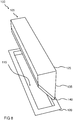
Figur 6 zeigt eine perspektivische Aufsicht auf eine Muldenlüftereinlasseinheit 100 gemäß einem Ausführungsbeispiel. Dabei kann es sich um eine der anhand einer derFiguren 1 ,3 oder4 beschriebenen Muldenlüftereinlasseinheiten 100 in der inFig. 1 dargestellten Stellung handeln. -
Figur 7 zeigt eine perspektivische Aufsicht auf eine Muldenlüftereinlasseinheit 100 gemäß einem Ausführungsbeispiel. Dabei kann es sich um eine der anhand einer derFiguren 1 ,3 ,4 oder6 beschriebenen Muldenlüftereinlasseinheiten 100 in der inFig. 3 dargestellten Stellung handeln. -
Figur 8 zeigt eine perspektivische Aufsicht auf eine Muldenlüftereinlasseinheit 100 gemäß einem Ausführungsbeispiel. Dabei kann es sich um einen der anhand einer derFiguren 1 ,3 ,4 ,6 oder7 beschriebenen Muldenlüftereinlasseinheiten 100 in der inFig. 4 dargestellten Stellung handeln. -
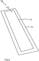
Figur 9 zeigt eine perspektivische Aufsicht auf eine Abdeckvorrichtung 105 gemäß einem Ausführungsbeispiel. Dabei kann es sich um eine der anhand einer der vorangegangenen Figuren beschriebenen Abdeckvorrichtungen 105 handeln, mit dem Unterschied, dass dieFiltereinrichtung 130 gemäß diesem Ausführungsbeispiel zumindest teilweise indem Deckel 125 aufgenommen ist. Hierzu weist derDeckel 125eine Durchgangsöffnung 900 auf, in der dieFiltereinrichtung 130 angeordnet ist.Die Durchgangsöffnung 900 ist dazu ausgeformt ist, um im aufgenommenen Zustand desDeckels 125 inder Muldenöffnung 115 ein Passieren von Wrasen indie Mulde 110 zu ermöglichen.Die Filtereinrichtung 130 weist gemäß diesem Ausführungsbeispiel kein Filtergestell auf und ist vollständig indem Deckel 125 aufgenommen.
-
FIG. 2 shows a side cross-section of acover 105 according to an embodiment. These may be the ones based onFig. 1 described coveringdevice 105 act. -
FIG. 3 shows a side cross-section of a wellventilator inlet unit 100 according to an embodiment. These may be the ones based onFig. 1 described troughfan inlet unit 100, with the difference that thecovering device 105 was partially moved out of thetrough opening 115 or pulled out according to this embodiment. Vapors can be sucked in this position of thecover 105 via twodischarge surfaces 300 in thecover 105 or removed. -
FIG. 4 shows a side cross-section of a wellventilator inlet unit 100 according to an embodiment. This may be the one of theFIGS. 1 or3 described with the difference that thecover 105 was completely pulled out of thetrough opening 115 according to this embodiment. -
FIG. 5 shows a side cross-section of acover 105 according to an embodiment. This may be one of the coveringdevices 105 described with reference to one of the preceding figures, with the difference that the coveringdevices 105 according to this embodiment have at least oneprotective element 500 which is designed to allow at least one gas and / or one gas flame to flow in in thecover 105 to prevent. According to this embodiment, thecovering device 105 has twoprotective elements 500, which may also be referred to as blocking elements. Theprotective elements 500 are formed according to this embodiment as two cover plates, which are arranged on an inner side of thefilter frame 135. Theprotection members 500 cover the vapor facing sides of thefilter rack 135 to a predetermined height to prevent gas from entering the well ventilator inlet unit when thecover 105 is received in the well opening. In this application, thelid 105 can be pulled out higher. In an alternative embodiment, theprotection element 500 may also be additively attached to thecover 105. -
FIG. 6 shows a perspective view of aMuldenlüftereinlasseinheit 100 according to an embodiment. This can be one of the basis of one ofFIGS. 1 .3 or4 describedMuldenlüftereinlasseinheiten 100 in the inFig. 1 act represented position. -
FIG. 7 shows a perspective view of aMuldenlüftereinlasseinheit 100 according to an embodiment. This can be one of the basis of one ofFIGS. 1 .3 .4 or6 describedMuldenlüftereinlasseinheiten 100 in the inFig. 3 act represented position. -
FIG. 8 shows a perspective view of aMuldenlüftereinlasseinheit 100 according to an embodiment. This can be one of the basis of one ofFIGS. 1 .3 .4 .6 or7 describedMuldenlüftereinlasseinheiten 100 in the inFig. 4 act represented position. -
FIG. 9 shows a perspective view of acover 105 according to an embodiment. This may be one of thecover devices 105 described with reference to one of the preceding figures, with the difference that thefilter device 130 according to this embodiment is at least partially accommodated in thecover 125. For this purpose, thelid 125 has apassage opening 900, in which thefilter device 130 is arranged. The through-opening 900 is shaped to allow passages of vapor into thetrough 110 when thelid 125 is received in thetrough opening 115. Thefilter device 130 according to this embodiment has no filter frame and is completely received in thelid 125.
Im Folgenden werden Ausführungsbeispiele anhand der
Gemäß diesem Ausführungsbeispiel ist die Abdeckvorrichtung 105 eine permanente Abdeckung mit integrierter Filtereinrichtung 130 aus Maschendraht stabiler Ausführung, z. B. verschweißt im Walzverfahren. Bei einer gezielt dimensionierten Drahtstärke und Maschenweite lässt sich hierbei auch eine schalldämmende Eigenschaft einstellen. Weiter bietet dieser Ansatz einen Flammenschutz gegen das Einsaugen zumindest einer Flamme eines neben der Muldenöffnung positionierten Gasbrenners im Bereich des Gaskochfelds. Vorteilhafterweise kann der Deckel 125 nicht in die Mulde fallen. Das Einlegen der Abdeckvorrichtung 105 in die Muldenöffnung ist einfach, von der Seite längs und quer schiebbar.According to this embodiment, the
Eine hier beschriebene permanente Abdeckung aus Maschendraht bietet Flammenschutz und verringert Schallgeräusche durch den Einsatz von Maschendraht anstelle von Glaskeramik. Die Abdeckung ist kundenfreundlicher als bekannte Deckel, sie braucht beim Einschalten der Absaugung nicht jedes Mal abgenommen und aufgelegt zu werden. Weiterhin bietet sie flammhemmende Eigenschaften, bzw. eine Flammsperre und verringert bei ausgesuchter Dimensionierung Lüftergeräusche der Saugöffnung bzw. Muldenöffnung.A permanent wire mesh cover described here provides flame protection and reduces sound noise through the use of wire mesh instead of glass ceramic. The cover is more customer-friendly than known covers, it does not need to be removed and placed on the suction each time. Furthermore, it offers flame-retardant properties, or a flame arrester and reduces with selected dimensioning fan noise of the suction opening or trough opening.
Die
Das zumindest abschnittsweise an dem Deckel 125 ausgebildete Gewebe, Gewirke, oder Gestricke in Form der Filtereinrichtung 130 kann als Fettfilter dienen. Vorzugsweise kann eine solche Abdeckvorrichtung 105 nach intensivem Gebrauch abgenommen und in der Spülmaschine gereinigt werden. Wird die Muldenöffnung mit einem z. B. weitmaschigen Gewebe verschlossen, kann dies gemäß einem in
Bei einer Verwendung eines Muldenlüfters neben einem Gasbrenner muss sichergestellt werden, dass der Muldenlüfter die Gasflamme nicht ansaugt. Diese könnte mit einer als ein Fettfilter ausgeformten Filtereinrichtung in Kontakt geraten und bei einem unzureichend gereinigten Fettfilter in dem Fettfilter haftende Fette entzünden. Eine hier vorgestellte Abdeckvorrichtung 105 kann zwischen der Muldenöffnung 105 und dem Gasbrenner aufgestellt werden und so eine Strömungsbarriere für die Flamme schaffen. Wrasen aus einem deutlich höher gelegenen Gargeschirr, z. B. aus einem Topf oder einer Pfanne, kann leicht über das aufgestellte Abdeckelement in die Muldenöffnung 115 strömen.When using a bowl ventilator next to a gas burner, make sure that the bowl ventilator does not suck the gas flame. This could come into contact with a filter device designed as a grease filter and ignite fats adhering to the grease filter if the grease filter is insufficiently cleaned. A
Im Folgenden werden Ausführungsbeispiele anhand der
Dargestellt ist in
Gemäß diesem Ausführungsbeispiel ist der Muldenlüfter oben durch eine luftdurchlässige, gewebeänhnliche Abdeckung in Form der Abdeckvorrichtung 105 mit dem feuerbeständigen Material 1400 optisch verschließbar. Die Abdeckvorrichtung 105 muss vorteilhafterweise beim Gebrauch des Muldenlüfters nicht aus der Muldenöffnung entfernt werden. Die Fläche des feuerbeständigen Materials 1400 ist dabei so luftdurchlässig, dass der Wrasen ohne große Verluste die Durchgangsöffnung 900 des Deckels 125 durchdringt und weiter unten im Muldenlüfter von der herkömmlichen Filtereinrichtung erfasst wird. Die Filtereinrichtung kann nach Entnahme des Deckels 125 mit dem feuerbeständigen Material 1400 aus der Muldenöffnung nach oben herausgenommen werden.According to this embodiment, the tray ventilator is optically closed at the top by an air-permeable, fabric-like cover in the form of the
Gemäß einem alternativen Ausführungsbeispiel wird der Muldenlüfter wie in
Claims (12)
Applications Claiming Priority (1)
| Application Number | Priority Date | Filing Date | Title |
|---|---|---|---|
| DE102016117788.1A DE102016117788A1 (en) | 2016-09-21 | 2016-09-21 | Covering device for a tray ventilator and tray ventilator inlet unit with a cover device |
Publications (1)
| Publication Number | Publication Date |
|---|---|
| EP3299727A1 true EP3299727A1 (en) | 2018-03-28 |
Family
ID=59738220
Family Applications (1)
| Application Number | Title | Priority Date | Filing Date |
|---|---|---|---|
| EP17188177.4A Withdrawn EP3299727A1 (en) | 2016-09-21 | 2017-08-28 | Covering fixture for a pit ventilator and pit ventilator inlet unit with a covering fixture |
Country Status (2)
| Country | Link |
|---|---|
| EP (1) | EP3299727A1 (en) |
| DE (1) | DE102016117788A1 (en) |
Cited By (1)
| Publication number | Priority date | Publication date | Assignee | Title |
|---|---|---|---|---|
| CN114222890A (en) * | 2019-08-21 | 2022-03-22 | Bsh家用电器有限公司 | Desk type ventilation device |
Citations (6)
| Publication number | Priority date | Publication date | Assignee | Title |
|---|---|---|---|---|
| US6455818B1 (en) * | 2001-08-23 | 2002-09-24 | Maytag Corporation | Downdraft filter assembly for a cooking appliance |
| DE102009025038A1 (en) * | 2009-06-10 | 2010-12-16 | Wilhelm Bruckbauer | Cooking fume inlet device with removable lid-shaped closing device |
| DE202013005303U1 (en) * | 2013-06-12 | 2013-06-24 | Wilhelm Bruckbauer | hob |
| WO2013167531A2 (en) * | 2012-05-11 | 2013-11-14 | BSH Bosch und Siemens Hausgeräte GmbH | Extraction device for extracting air from a stove |
| DE102013007722A1 (en) * | 2013-05-07 | 2014-11-13 | Exklusiv-Hauben Gutmann Gmbh | Trough ventilation for extracting cooking vapors from a hob |
| DE102016207087A1 (en) * | 2016-04-26 | 2017-10-26 | BSH Hausgeräte GmbH | Kitchen appliance with hob and extractor device and method for operating a fume extraction device |
Family Cites Families (4)
| Publication number | Priority date | Publication date | Assignee | Title |
|---|---|---|---|---|
| US4446849A (en) | 1981-08-24 | 1984-05-08 | The Tappan Company | Vent apparatus for a surface cooking appliance |
| DE10106307C2 (en) | 2001-02-12 | 2003-10-02 | Bsh Bosch Siemens Hausgeraete | grease filter |
| DE202011109570U1 (en) | 2011-12-28 | 2012-03-01 | Wilhelm Bruckbauer | Cooktop extractor with one or more plate packs for reversible closing and opening of the cooking fume inlet opening |
| KR101486725B1 (en) | 2014-09-29 | 2015-01-29 | 주식회사 홈쿠벤 | An Induction for supply and exhaust ventilation system |
-
2016
- 2016-09-21 DE DE102016117788.1A patent/DE102016117788A1/en not_active Withdrawn
-
2017
- 2017-08-28 EP EP17188177.4A patent/EP3299727A1/en not_active Withdrawn
Patent Citations (6)
| Publication number | Priority date | Publication date | Assignee | Title |
|---|---|---|---|---|
| US6455818B1 (en) * | 2001-08-23 | 2002-09-24 | Maytag Corporation | Downdraft filter assembly for a cooking appliance |
| DE102009025038A1 (en) * | 2009-06-10 | 2010-12-16 | Wilhelm Bruckbauer | Cooking fume inlet device with removable lid-shaped closing device |
| WO2013167531A2 (en) * | 2012-05-11 | 2013-11-14 | BSH Bosch und Siemens Hausgeräte GmbH | Extraction device for extracting air from a stove |
| DE102013007722A1 (en) * | 2013-05-07 | 2014-11-13 | Exklusiv-Hauben Gutmann Gmbh | Trough ventilation for extracting cooking vapors from a hob |
| DE202013005303U1 (en) * | 2013-06-12 | 2013-06-24 | Wilhelm Bruckbauer | hob |
| DE102016207087A1 (en) * | 2016-04-26 | 2017-10-26 | BSH Hausgeräte GmbH | Kitchen appliance with hob and extractor device and method for operating a fume extraction device |
Cited By (2)
| Publication number | Priority date | Publication date | Assignee | Title |
|---|---|---|---|---|
| CN114222890A (en) * | 2019-08-21 | 2022-03-22 | Bsh家用电器有限公司 | Desk type ventilation device |
| CN114222890B (en) * | 2019-08-21 | 2024-08-20 | Bsh家用电器有限公司 | Desktop ventilation unit |
Also Published As
| Publication number | Publication date |
|---|---|
| DE102016117788A1 (en) | 2018-03-22 |
Similar Documents
| Publication | Publication Date | Title |
|---|---|---|
| EP3338031B1 (en) | Combined device with cooking hob and vapour extraction unit | |
| EP3338028B1 (en) | Combined device with cooking hob and vapour extraction unit | |
| EP3701192B1 (en) | Combination device with an extractor device and a cooker hob | |
| DE102012103286A1 (en) | griller | |
| DE102013007722A1 (en) | Trough ventilation for extracting cooking vapors from a hob | |
| EP3502571B1 (en) | Vapour extraction device, kitchen appliance with hob and vapour extraction device and method for operating a vapour extraction device | |
| DE102013206748A1 (en) | Grate for intake opening of e.g. hollow fan in fume extraction hood that is attached over grill for sucking cooking fumes in kitchen, has longitudinal bar spaced from outer rim of grate and inclined to surface of lattice at specific angle | |
| DE102011079306B4 (en) | fan device and hob arrangement | |
| EP3710756A1 (en) | Range hood device for a cooktop and kitchen furniture with range hood device | |
| DE102005030038B4 (en) | Cooktop extractor | |
| EP3710755A1 (en) | Range hood device for a cooktop and kitchen furniture with range hood device | |
| EP2829808B1 (en) | Extractor hood | |
| DE102012222415A1 (en) | Vapor fume hood for use in cooking field, has baffle plate that is arranged at viewing hood, and flat panel that is formed by front side of viewing hood in operating mode of main portion | |
| EP3299727A1 (en) | Covering fixture for a pit ventilator and pit ventilator inlet unit with a covering fixture | |
| EP2554917B1 (en) | Device for extracting air from a hob | |
| WO2008135443A1 (en) | Extractor device | |
| DE19950817A1 (en) | Extractor hood | |
| DE10015745A1 (en) | Extractor hood | |
| DE102018130963A1 (en) | Extractor hood for a cabinet or kitchen unit | |
| EP3301375A1 (en) | Covering device for a pit ventilator and pit ventilator inlet unit with a covering device | |
| DE202005010164U1 (en) | Cooker hood for cookers comprises channel-like attachments which protrude over the horizontal surface of the hob in the vertical direction | |
| DE102007003934A1 (en) | Extractor hood, comprises extraction opening, which is inserted to filter surface and is adjustable, where filter surface and extraction opening are functionally connected with suction unit | |
| DE10000841A1 (en) | Fumes extractor hood has rectangular base surface, grease-collector dish, filter arrangement, chimney with housing, motor and fan | |
| EP3299728A1 (en) | Covering fixture for a pit ventilator and pit ventilator inlet unit with a covering fixture | |
| EP0943871B1 (en) | Extraction hood for kitchens |
Legal Events
| Date | Code | Title | Description |
|---|---|---|---|
| PUAI | Public reference made under article 153(3) epc to a published international application that has entered the european phase |
Free format text: ORIGINAL CODE: 0009012 |
|
| AK | Designated contracting states |
Kind code of ref document: A1 Designated state(s): AL AT BE BG CH CY CZ DE DK EE ES FI FR GB GR HR HU IE IS IT LI LT LU LV MC MK MT NL NO PL PT RO RS SE SI SK SM TR |
|
| AX | Request for extension of the european patent |
Extension state: BA ME |
|
| STAA | Information on the status of an ep patent application or granted ep patent |
Free format text: STATUS: THE APPLICATION IS DEEMED TO BE WITHDRAWN |
|
| 18D | Application deemed to be withdrawn |
Effective date: 20180929 |