EP3299727A1 - Dispositif de revêtement pour une bouche d'aération à cuvette et unité d'entrée de la bouche d'aération à cuvette pourvue d'un dispositif de revêtement - Google Patents
Dispositif de revêtement pour une bouche d'aération à cuvette et unité d'entrée de la bouche d'aération à cuvette pourvue d'un dispositif de revêtement Download PDFInfo
- Publication number
- EP3299727A1 EP3299727A1 EP17188177.4A EP17188177A EP3299727A1 EP 3299727 A1 EP3299727 A1 EP 3299727A1 EP 17188177 A EP17188177 A EP 17188177A EP 3299727 A1 EP3299727 A1 EP 3299727A1
- Authority
- EP
- European Patent Office
- Prior art keywords
- opening
- filter
- trough
- lid
- cover
- Prior art date
- Legal status (The legal status is an assumption and is not a legal conclusion. Google has not performed a legal analysis and makes no representation as to the accuracy of the status listed.)
- Withdrawn
Links
Images


Classifications
-
- F—MECHANICAL ENGINEERING; LIGHTING; HEATING; WEAPONS; BLASTING
- F24—HEATING; RANGES; VENTILATING
- F24C—DOMESTIC STOVES OR RANGES ; DETAILS OF DOMESTIC STOVES OR RANGES, OF GENERAL APPLICATION
- F24C15/00—Details
- F24C15/20—Removing cooking fumes
- F24C15/2042—Devices for removing cooking fumes structurally associated with a cooking range e.g. downdraft
Definitions
- the approach presented here relates to a cover device for a tray ventilator and a tray ventilator inlet unit with a cover device.
- a bowl ventilator When it is switched on, a bowl ventilator should suck in as much vapor as possible through a gap that is as large as possible and be closed by a lid when not in use and visually inconspicuous in the living environment of the kitchen. If the lid of the bowl ventilator needs to be removed / released from the bowl ventilator during operation of the bowl ventilator, it may be lost.
- the DE 10 2009 025 038 A1 describes a device for the withdrawal of cooking fumes in vertically below a cooking field level direction with a one or more parts, removable lid-shaped closing device for reversibly closing the inlet opening of the cooking fume inlet device.
- the approach presented here has the object to provide an improved cover device for a well ventilator and an improved Muldenllibraryereinlassech with a cover.
- a cover device for a tray ventilator has at least one lid and a filter device.
- the lid is shaped to be received by a trough opening of a trough of the tray fan to at least partially close the tray opening.
- the lid may also be shaped to completely shoot the well opening in the received state to cover and protect components of the well ventilator disposed in the well while the well ventilator is not operating.
- the filter device is durable with the lid, d. H. insoluble, connected.
- Dump ventilators are designed to suck in vapors, which may be formed, for example, during cooking in the region of a hob, downwards through a well opening in a depression of the well ventilator.
- the trough opening is usually in the area of Hob, for example, embedded in a center of the hob or arranged in the region of an edge of the hob.
- a filter device is usually formed as a frame with a filter, but the filter device can also be formed only as the filter.
- the filter device is often arranged in a low-lying region of the trough from the trough opening.
- the filter is usually formed to filter fat from the vapor, but may also be shaped to protect against a flame of a gas burner.
- the filter device can be arranged in the region of the cover and thus, for example, removal of the cover from a trough fan inlet unit of the trough ventilator or from the trough opening during operation of the trough ventilator is unnecessary.
- lid and filter device of the tray fan always remain one unit and no parts of the tray fan are lost.
- the filter device For receiving a filter unit that can be positioned deep in the trough, the filter device can have a filter frame and the filter unit that is received by the filter frame, wherein the filter frame can be arranged between the lid and the filter unit and can be shaped as a grease filter.
- the filter rack can serve as a connector between the lid and the filter unit.
- the filter unit can be arranged transversely to the lid.
- the covering device may have an opening device which is designed to enable the covering device to be moved out of the depression opening mechanically and / or magnetically and / or motorily in a state received in the depression opening.
- the filter device can be at least partially extended out of the well opening in the direction of the hob or pulled out to allow withdrawal of Wrasens through lateral longitudinal sides of the filter frame into the trough.
- the cover can be securely held in the well opening in the well opening in the well opening in the well opening in the well opening, if in the region of the well also a magnet is arranged.
- slipping of the lid can be counteracted by light touches.
- the filter device has at least one protective element, for example a cover plate or a wire mesh, this can prevent at least one gas and / or one gas flame from flowing into the covering device.
- a protective element for example a cover plate or a wire mesh
- the protective element on two of the longitudinal sides of the filter frame on an inner side and / or an outer side of the longitudinal sides arranged.
- the wire mesh can also be arranged on a filter device arranged in the region of the lid, or the filter device itself can be at least partially shaped as the wire mesh.
- the cover may have at least one passage opening, which may be formed to allow passage of vapor into the recess in the recess opening in the cavity opening.
- the lid can remain accommodated during operation of the hollow ventilator in the well ventilator opening.
- At least one fire-resistant material can be arranged in the passage opening.
- Fireproofing is to be understood as meaning a nonflammable material which has at least one fire resistance of a period of time defined within a tolerance range. This period of time may be, for example, at least 10 minutes.
- the refractory material may be a wire mesh formed to prevent entry of at least one gas and / or gas flame from a gas burner into the trough.
- the filter device may be at least partially received in the lid.
- the filter device can be arranged flush with a surrounding the trough opening frame member of the trough in the trough opening and span it at least partially.
- the vapors can thus be filtered directly on entering the trough opening and the lid, even if the filter device according to one embodiment advantageously formed wras trimelle remain during the operation of the trough blower in the trough opening remain.
- the lid When the lid is shaped to be deployable or hinged at least partially transverse to the well opening from the well, the lid in the erected condition between the well opening and a gas burner can serve as a flow barrier for at least one gas flame to prevent the lid Gas flame jumps into the trough or gas enters the trough.
- the cover device may also be shaped to be displaceable in the well opening in the well opening in the well opening.
- the covering device can be displaced longitudinally and / or transversely, for example, from the side.
- the trough opening can be partially opened by moving and enter the vapors during operation of the trough blower in the trough, while a large part of the trough opening can remain closed.
- a tray fan inlet unit for a tray ventilator has at least the well described and one of the presented cover devices, wherein the lid of the cover device is received in the well opening of the tray.
- a trough fan inlet unit presented here can serve as a substitute for known trough fan inlet units, the presented trough fan inlet unit advantageously realizing the already presented advantages of the cover device.
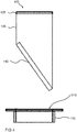
- FIG. 1 shows a side cross-section of a well ventilator unit 100 for a well ventilator with a cover 105 according to an embodiment.
- the trough fan inlet unit 100 has at least one trough 110 with a trough opening 115 and the covering device 105.
- the trough 110 has, around the trough opening 115, a frame element 120 which surrounds the trough opening 115 adapted to be arranged or adjacent to a hob of a hearth.
- the covering device 105 is accommodated in the depression opening 115 such that a cover 125 of the covering device 105 closes the depression opening 115.
- the covering device 105 has a filter device 130.
- the filter device 130 is permanently connected to the lid 125.
- the filter device 130 has a filter frame 135 and a filter unit 140.
- the filter unit 140 is received by the filter rack 135, which is arranged between the lid 115 and the filter unit 140.
- the filter unit 140 is arranged transversely to the lid 125.
- the presented here Muldenllibraryereinlassech 100 can also be referred to as a tray ventilator with filter element incl.
- Cover since the cover is formed in the form of the lid 125 in one piece with the filter element in the form of the filter device 130.
- the lid 125 of the device in the form of the well filter device 105 is according to this embodiment structurally a unit with the filter device 130.
- a mechanical, z. B. a push-pull mechanism, and / or magnetic and / or motor opening mechanism in the cover 105 in the form of an opening device z. B.
- the lid 125 is mechanically and / or magnetically and / or motor-opened.
- the unit of cover 125 and filter device 130 moves vertically, parallel to the trough 110 and to the built-in housing in the form of the housing member 120 by a certain amount, for. B. 20 mm in height.
- a fan can now be started, whereby Wrasen laterally, ie left and right of the projecting beyond the housing member 120 part of the filter frame 135, is discharged. If the user desires a larger discharge surface or opening, he can achieve this by simply pulling up the lid 125. When the lid 125 is completely removed, the filter unit 140 associated with the lid 125 can be removed and cleaned.
- the lid 125 is in this embodiment handle of the filter rack 135 and the filter unit 140 and the filter rack 135 holds the filter unit 140.
- the essential object of the approach here is less a generation of a vertically or horizontally oriented opening for removing the Wrasens, but rather a question, which relates to a simplified handling of the exchangeable filter unit 140 and a handling of the lid 125.
- the user does not want to see the filter device 130 due to a possible contamination during operation and reluctant in the removal of the filter device 130 for fear of injury or due to handling outside the field of view the trough opening 115 engage. Furthermore, the user does not want to touch the filter device 130 to be cleaned for reasons of hygiene.
- the approach further provides through the opening means a simple but staged movement of the lid 125, a show effect, and a fixed storage location for the lid 125 when using the fan.
- the approach provides a solution to all these questions:
- the lid 125 forms a unit with the filter rack 135.
- the filter unit 140 is inserted in the filter rack 135 and the lid 125 is attached as a handle on the filter rack 135.
- the lid 125 as a handle serves to make the unit in the form of the cover 105, for example, for cleaning or filter replacement, easy to remove.
- the cover device 105 is removed, the filter unit 140 is easily accessible outside the trough opening 115. Possibly.
- the entire cover device 105, including the filter device 140 which may be a grease filter, can be placed in a dishwasher.
- the vertical process between a rest position and an operating position can be solved differently, namely purely motor or purely mechanically or by mixing.
- An at least two-stage extension between a supply / operating position shown here and an in Fig. 3 and 7 shown removal position is possible.
- a trigger for the adjustment can be initiated manually, for example by pressing a button or Push-To-Open, or automatically done with a switch on the fan or the steam exhaust hood.
- a use of an in Fig. 5 Locking elements shown is possible on both longitudinal sides of the filter rack 135, so as to allow operation of a well ventilator with the Muldenlcertainereinlassech 100 next to a gas hob, wherein the blocking element prevents a gas flame or unburned gas is sucked into the cover 105.
- the filter in the form of the filter unit 140 is accordingly easy and convenient to remove from the well ventilator inlet unit 100.
- the lid 125 does not have to be removed separately.
- the opening mechanism serves an enthusiasm factor and an aesthetic appearance of the covering device 105.
- exhaust hoods often have an open suction duct in the form of the trough in the cooking surface during an active extraction.
- the trough opening is covered with a cover, for example made of glass ceramic.
- the cover in the form of the lid 125 may be flat for shielding the gas hob only to cover the suction channel and only of glass ceramic.
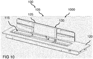
- the lid 125 can also as in Figure 10 described to be set up.
- the cover 105 is a permanent cover with integrated filter device 130 of wire mesh stable design, z. B. welded in the rolling process.
- a sound-insulating property can also be set.
- this approach provides flame protection against the suction of at least one flame a positioned next to the trough opening gas burner in the gas hob.
- the lid 125 can not fall into the trough. The insertion of the cover 105 in the well opening is simple, longitudinally and transversely from the side pushed.
- a permanent wire mesh cover described here provides flame protection and reduces sound noise through the use of wire mesh instead of glass ceramic.
- the cover is more customer-friendly than known covers, it does not need to be removed and placed on the suction each time. Furthermore, it offers flame-retardant properties, or a flame arrester and reduces with selected dimensioning fan noise of the suction opening or trough opening.
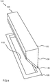
- FIGS. 9 to 14 show a flush design of the cover 105.
- the cover 105 is at least partially designed as flush with the lid 125 designed filter device 130.
- the filter device 130 which can also be referred to as a filter element, serve as a grease filter or alternatively as a flame filter.
- the at least partially formed on the lid 125 fabric, knitted or knitted fabric in the form of the filter device 130 may serve as a grease filter.
- a covering device 105 can be removed after intensive use and cleaned in the dishwasher.
- the trough opening with a z. B. closed mesh fabric this can according to a in Fig. 14 illustrated alternative embodiment to prevent a flame passage.
- the fabric is preferably made of a fire-resistant material and so wide that extremely little, preferably no fat can attach to it. This is achieved because the cold metal fabric deprives the flame of energy and a passing flame goes out. The flame, if it reaches the net or tissue, would cling to it and rise to the top, but not pass through.
- This embodiment also allows a closed trough opening when using the tray ventilator, thereby preventing objects such as spoons, knives and / or foods, such as or noodles, from falling into the trough.
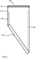
- FIG. 10 shows a perspective side view of a well ventilator inlet unit 100 according to an embodiment. This can be one of the basis of one of FIGS. 1 . 3 . 4 . 6 . 7 or 8th described with the difference that the lid 125 can be set up in a set-up 1000, in which the lid 125 itself forms the filter device 130. The lid 125 has been folded in the set-up position 1000 shown here transversely to the trough opening 115 of the trough 110 away.
- a capping device 105 presented here can be placed between the well opening 105 and the gas burner and thus create a flow barrier for the flame. Wrasen from a much higher garnish, z. B. from a pot or pan, can easily flow over the established cover in the trough opening 115.
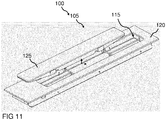
- FIG. 11 shows a perspective view of a Muldenlalthoughereinlassech 100 according to an embodiment. These may be the ones based on Fig. 10 described with the difference that the lid 125 is not placed, but in the trough opening 115 has been moved longitudinally and transversely from the side. The trough opening 115 is partially closed in this position of the lid 125.
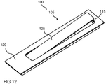
- FIG. 12 shows a perspective view of a Muldenlrangeereinlassech 100 according to an embodiment. These may be the ones based on Fig. 11 described with the difference that the cover has been moved so that it almost completely closes the trough opening 115.
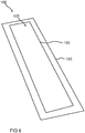
- FIG. 13 shows a perspective view of a well opening 115 of a Muldenlrangeereinlassech. It may be one of the well openings 115 of the basis of one of FIGS. 10 to 12 act described Muldenlalthoughereinlassechen.
- Two T-shaped members 1300 extend from two ends of the trough opening 115 toward a center of the trough opening 115, the shorter side of the T-shaped members 1300 facing the center of the trough opening 115 and arranged transversely to a main extension length of the trough opening 115.
- the T-shaped members 1300 are formed to be one of the basis of the FIGS. 9 to 12 record and keep in the trough opening 115, without that this can fall into the trough.
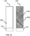
- FIG. 14 shows a plan view of a cover 105 according to an embodiment. These may be the ones based on Fig. 9 described covering device 105, with the difference that the covering device 105 instead of the filter device in the through-hole 900, the fire-resistant material 1400 and the filter device as in the FIGS. 1 to 8 is arranged on the cover 105.
- a cover device 105 with a fabric cover in the form of fire-resistant material 1400 Is shown in Fig. 14 a cover device 105 with a fabric cover in the form of fire-resistant material 1400.
- Filter devices of trough blowers are usually in the bottom of a trough in the trough blower and when not in use by the lid 125 o. covered.
- the well opening of the well ventilator is often open, the user can look into the well and, if necessary, parts such as cooking utensils or food can fall into the well.
- the filter means can only be removed unergonomically through the small trough opening or down from the trough blower.
- the tray ventilator is optically closed at the top by an air-permeable, fabric-like cover in the form of the covering device 105 with the refractory material 1400.
- the covering device 105 advantageously does not have to be removed from the depression opening during use of the depression ventilator.
- the surface of the fire-resistant material 1400 is so permeable to air that the vapor penetrates the through-opening 900 of the lid 125 without great losses and is detected below in the trough blower of the conventional filter device.
- the filter device can be removed after removal of the lid 125 with the refractory material 1400 from the trough opening upwards.
- the well ventilator is as in Fig. 9 above in the region of the trough opening by an air-permeable, filter-like cover, for example of a fabric, for. B. metal and / or a perforated or microperforated surface of metal, plastic and / or glass optically closed, the cover also need not be removed when using the hollow fan.
- the fabric meets the functional requirements of the filter device so that the filter device is no longer needed at the bottom of the tray ventilator. As a result, the entire device height of the tray ventilator could be reduced enormously.
- the filter device is always covering on the trough opening, in the active and inactive state of the trough blower, and after each use easy z. B. be cleaned in the dishwasher.
- the cover 105 is a further advantage that the Muldenllibraryereinlassiki saves by the flat-lying filter device much height, otherwise by a in the FIGS. 1 to 8 shown tilted filter unit inside the trough arises.
- the cover is flush or almost flush with adjacent devices such as hobs, CombiSet devices or a worktop.
- the cover 105 is easy to remove to clean the bowl ventilator inside.
- the refractory material 1400 or the filter device in the through-opening 900 can consist of different materials, eg. B. from textile, plastic, stainless steel, other composites, eg. As fiberglass composite, and may be made in one piece / single-layer or multi-part / multi-layered.
- FIG. 15 11 shows a plan view of a fire-resistant material 1400 and a cross-section of a fire-resistant material 1400 according to an exemplary embodiment. This may be the in Fig. 14 described fire-resistant material 1400 act.
Landscapes
- Engineering & Computer Science (AREA)
- Chemical & Material Sciences (AREA)
- Combustion & Propulsion (AREA)
- Mechanical Engineering (AREA)
- General Engineering & Computer Science (AREA)
- Filtering Of Dispersed Particles In Gases (AREA)
Applications Claiming Priority (1)
| Application Number | Priority Date | Filing Date | Title |
|---|---|---|---|
| DE102016117788.1A DE102016117788A1 (de) | 2016-09-21 | 2016-09-21 | Abdeckvorrichtung für einen Muldenlüfter und Muldenlüftereinlasseinheit mit einer Abdeckvorrichtung |
Publications (1)
| Publication Number | Publication Date |
|---|---|
| EP3299727A1 true EP3299727A1 (fr) | 2018-03-28 |
Family
ID=59738220
Family Applications (1)
| Application Number | Title | Priority Date | Filing Date |
|---|---|---|---|
| EP17188177.4A Withdrawn EP3299727A1 (fr) | 2016-09-21 | 2017-08-28 | Dispositif de revêtement pour une bouche d'aération à cuvette et unité d'entrée de la bouche d'aération à cuvette pourvue d'un dispositif de revêtement |
Country Status (2)
| Country | Link |
|---|---|
| EP (1) | EP3299727A1 (fr) |
| DE (1) | DE102016117788A1 (fr) |
Cited By (1)
| Publication number | Priority date | Publication date | Assignee | Title |
|---|---|---|---|---|
| CN114222890A (zh) * | 2019-08-21 | 2022-03-22 | Bsh家用电器有限公司 | 台式通风装置 |
Citations (6)
| Publication number | Priority date | Publication date | Assignee | Title |
|---|---|---|---|---|
| US6455818B1 (en) * | 2001-08-23 | 2002-09-24 | Maytag Corporation | Downdraft filter assembly for a cooking appliance |
| DE102009025038A1 (de) * | 2009-06-10 | 2010-12-16 | Wilhelm Bruckbauer | Kochdunst-Eintrittsvorrichtung mit abnehmbarer deckelförmiger Verschließeinrichtung |
| DE202013005303U1 (de) * | 2013-06-12 | 2013-06-24 | Wilhelm Bruckbauer | Kochfeld |
| WO2013167531A2 (fr) * | 2012-05-11 | 2013-11-14 | BSH Bosch und Siemens Hausgeräte GmbH | Dispositif d'aspiration destiné à aspirer l'air dans l'environnement d'une table de cuisson |
| DE102013007722A1 (de) * | 2013-05-07 | 2014-11-13 | Exklusiv-Hauben Gutmann Gmbh | Muldenlüftung zum Abzug von Kochdämpfen an einem Kochfeld |
| DE102016207087A1 (de) * | 2016-04-26 | 2017-10-26 | BSH Hausgeräte GmbH | Küchengerät mit Kochfeld und Dunstabzugsvorrichtung und Verfahren zum Betreiben einer Dunstabzugsvorrichtung |
Family Cites Families (4)
| Publication number | Priority date | Publication date | Assignee | Title |
|---|---|---|---|---|
| US4446849A (en) | 1981-08-24 | 1984-05-08 | The Tappan Company | Vent apparatus for a surface cooking appliance |
| DE10106307C2 (de) | 2001-02-12 | 2003-10-02 | Bsh Bosch Siemens Hausgeraete | Fettfilter |
| DE202011109570U1 (de) | 2011-12-28 | 2012-03-01 | Wilhelm Bruckbauer | Kochfeldabzug mit einem oder mehreren Plattenpaketen zum reversiblen Verschließen und Öffnen der Kochdunst-Eintrittsöffnung |
| KR101486725B1 (ko) | 2014-09-29 | 2015-01-29 | 주식회사 홈쿠벤 | 급배기 겸용 인덕션 환기시스템 |
-
2016
- 2016-09-21 DE DE102016117788.1A patent/DE102016117788A1/de not_active Withdrawn
-
2017
- 2017-08-28 EP EP17188177.4A patent/EP3299727A1/fr not_active Withdrawn
Patent Citations (6)
| Publication number | Priority date | Publication date | Assignee | Title |
|---|---|---|---|---|
| US6455818B1 (en) * | 2001-08-23 | 2002-09-24 | Maytag Corporation | Downdraft filter assembly for a cooking appliance |
| DE102009025038A1 (de) * | 2009-06-10 | 2010-12-16 | Wilhelm Bruckbauer | Kochdunst-Eintrittsvorrichtung mit abnehmbarer deckelförmiger Verschließeinrichtung |
| WO2013167531A2 (fr) * | 2012-05-11 | 2013-11-14 | BSH Bosch und Siemens Hausgeräte GmbH | Dispositif d'aspiration destiné à aspirer l'air dans l'environnement d'une table de cuisson |
| DE102013007722A1 (de) * | 2013-05-07 | 2014-11-13 | Exklusiv-Hauben Gutmann Gmbh | Muldenlüftung zum Abzug von Kochdämpfen an einem Kochfeld |
| DE202013005303U1 (de) * | 2013-06-12 | 2013-06-24 | Wilhelm Bruckbauer | Kochfeld |
| DE102016207087A1 (de) * | 2016-04-26 | 2017-10-26 | BSH Hausgeräte GmbH | Küchengerät mit Kochfeld und Dunstabzugsvorrichtung und Verfahren zum Betreiben einer Dunstabzugsvorrichtung |
Cited By (2)
| Publication number | Priority date | Publication date | Assignee | Title |
|---|---|---|---|---|
| CN114222890A (zh) * | 2019-08-21 | 2022-03-22 | Bsh家用电器有限公司 | 台式通风装置 |
| CN114222890B (zh) * | 2019-08-21 | 2024-08-20 | Bsh家用电器有限公司 | 台式通风装置 |
Also Published As
| Publication number | Publication date |
|---|---|
| DE102016117788A1 (de) | 2018-03-22 |
Similar Documents
| Publication | Publication Date | Title |
|---|---|---|
| EP3338031B1 (fr) | Appareil combiné avec plaque de cuisson et dispositif d'evacuation des fumées | |
| EP3338028B1 (fr) | Appareil combiné avec plaque de cuisson et dispositif d'evacuation des fumées | |
| EP3701192B1 (fr) | Appareil combiné comprenant un dispositif d'aspiration de fumées et une plaque de cuisson | |
| DE102012103286A1 (de) | Grillvorrichtung | |
| DE102013007722A1 (de) | Muldenlüftung zum Abzug von Kochdämpfen an einem Kochfeld | |
| EP3502571B1 (fr) | Dispositif d'aspiration de fumées, appareil de cuisine pourvu de plaque de cuisson et de dispositif d'aspiration de fumées et procédé de fonctionnement d'un dispositif d'aspiration de fumées | |
| DE102013206748A1 (de) | Rost für eine Dunstabzugsvorrichtung und Dunstabzugsvorrichtung | |
| DE102011079306B4 (de) | Lüftervorrichtung und Kochfeldanordnung | |
| EP3710756A1 (fr) | Dispositif d'aspiration des fumées pour une table de cuisson et meuble de cuisine doté d'un dispositif d'aspiration des fumées | |
| DE102005030038B4 (de) | Kochfeldabzugsvorrichtung | |
| EP3710755A1 (fr) | Dispositif d'une hotte aspirante destiné à une table de cuisson et meuble de cuisine équipé d'un dispositif de hotte aspirante | |
| EP2829808B1 (fr) | Hotte aspirante | |
| DE102012222415A1 (de) | Dunstabzugshaube | |
| EP3299727A1 (fr) | Dispositif de revêtement pour une bouche d'aération à cuvette et unité d'entrée de la bouche d'aération à cuvette pourvue d'un dispositif de revêtement | |
| EP2554917B1 (fr) | Dispositif d'aspiration d'air pour une table de cuisson | |
| WO2008135443A1 (fr) | Hotte aspirante | |
| DE19950817A1 (de) | Dunstabzugsvorrichtung | |
| DE10015745A1 (de) | Dunstabzugsvorrichtung | |
| DE102018130963A1 (de) | Dunstabzugseinrichtung für eine Schrank- oder Küchenzeile | |
| EP3301375A1 (fr) | Dispositif de revêtement pour une bouche d'aération à cuvette et unité d'entrée de la bouche d'aération à cuvette pourvue d'un dispositif de revêtement | |
| DE202005010164U1 (de) | Kochfeldabzugsvorrichtung | |
| DE102007003934A1 (de) | Dunstabzugshaube | |
| DE10000841A1 (de) | Dunstabzugsvorrichtung | |
| EP3299728A1 (fr) | Dispositif de revêtement pour une bouche d'aération à cuvette et unité d'entrée de la bouche d'aération à cuvette pourvue d'un dispositif de revêtement | |
| EP0943871B1 (fr) | Hotte d'évacuation de fumée pour cuisine |
Legal Events
| Date | Code | Title | Description |
|---|---|---|---|
| PUAI | Public reference made under article 153(3) epc to a published international application that has entered the european phase |
Free format text: ORIGINAL CODE: 0009012 |
|
| AK | Designated contracting states |
Kind code of ref document: A1 Designated state(s): AL AT BE BG CH CY CZ DE DK EE ES FI FR GB GR HR HU IE IS IT LI LT LU LV MC MK MT NL NO PL PT RO RS SE SI SK SM TR |
|
| AX | Request for extension of the european patent |
Extension state: BA ME |
|
| STAA | Information on the status of an ep patent application or granted ep patent |
Free format text: STATUS: THE APPLICATION IS DEEMED TO BE WITHDRAWN |
|
| 18D | Application deemed to be withdrawn |
Effective date: 20180929 |