EP3299740B9 - Registre destiné à être utilisé dans une conduite d'une installation de ventilation et de climatisation ou d'une installation de désenfumage mécanique - Google Patents
Registre destiné à être utilisé dans une conduite d'une installation de ventilation et de climatisation ou d'une installation de désenfumage mécanique Download PDFInfo
- Publication number
- EP3299740B9 EP3299740B9 EP17166224.0A EP17166224A EP3299740B9 EP 3299740 B9 EP3299740 B9 EP 3299740B9 EP 17166224 A EP17166224 A EP 17166224A EP 3299740 B9 EP3299740 B9 EP 3299740B9
- Authority
- EP
- European Patent Office
- Prior art keywords
- seal
- louvre
- slats
- slat
- closed position
- Prior art date
- Legal status (The legal status is an assumption and is not a legal conclusion. Google has not performed a legal analysis and makes no representation as to the accuracy of the status listed.)
- Active
Links
Images


Classifications
-
- F—MECHANICAL ENGINEERING; LIGHTING; HEATING; WEAPONS; BLASTING
- F24—HEATING; RANGES; VENTILATING
- F24F—AIR-CONDITIONING; AIR-HUMIDIFICATION; VENTILATION; USE OF AIR CURRENTS FOR SCREENING
- F24F13/00—Details common to, or for air-conditioning, air-humidification, ventilation or use of air currents for screening
- F24F13/08—Air-flow control members, e.g. louvres, grilles, flaps or guide plates
- F24F13/10—Air-flow control members, e.g. louvres, grilles, flaps or guide plates movable, e.g. dampers
- F24F13/14—Air-flow control members, e.g. louvres, grilles, flaps or guide plates movable, e.g. dampers built up of tilting members, e.g. louvre
- F24F13/15—Air-flow control members, e.g. louvres, grilles, flaps or guide plates movable, e.g. dampers built up of tilting members, e.g. louvre with parallel simultaneously tiltable lamellae
-
- F—MECHANICAL ENGINEERING; LIGHTING; HEATING; WEAPONS; BLASTING
- F24—HEATING; RANGES; VENTILATING
- F24F—AIR-CONDITIONING; AIR-HUMIDIFICATION; VENTILATION; USE OF AIR CURRENTS FOR SCREENING
- F24F13/00—Details common to, or for air-conditioning, air-humidification, ventilation or use of air currents for screening
- F24F13/08—Air-flow control members, e.g. louvres, grilles, flaps or guide plates
- F24F13/10—Air-flow control members, e.g. louvres, grilles, flaps or guide plates movable, e.g. dampers
- F24F13/14—Air-flow control members, e.g. louvres, grilles, flaps or guide plates movable, e.g. dampers built up of tilting members, e.g. louvre
- F24F13/1406—Air-flow control members, e.g. louvres, grilles, flaps or guide plates movable, e.g. dampers built up of tilting members, e.g. louvre characterised by sealing means
-
- F—MECHANICAL ENGINEERING; LIGHTING; HEATING; WEAPONS; BLASTING
- F24—HEATING; RANGES; VENTILATING
- F24F—AIR-CONDITIONING; AIR-HUMIDIFICATION; VENTILATION; USE OF AIR CURRENTS FOR SCREENING
- F24F11/00—Control or safety arrangements
- F24F11/30—Control or safety arrangements for purposes related to the operation of the system, e.g. for safety or monitoring
- F24F11/32—Responding to malfunctions or emergencies
- F24F11/33—Responding to malfunctions or emergencies to fire, excessive heat or smoke
- F24F11/35—Responding to malfunctions or emergencies to fire, excessive heat or smoke by closing air passages
Definitions
- the invention relates to a louvre flap for use in a line of an air conditioning and ventilation system or a mechanical smoke extraction system (MRA) comprising, on the one hand, a frame which forms a rectangular opening for the flow of a gaseous medium, and on the other hand at least two rectangular slats, wherein each lamella, preferably coextensive with at least one further lamella, is pivotally mounted in the frame between its closed position and its open position about a respective pivot axis, and each lamella has on the one hand two longitudinal edges oriented parallel to its pivot axis and on the other hand two side edges oriented orthogonally to its pivot axis , wherein the pivot axis, preferably in the middle, is arranged between the longitudinal edges, and wherein at least one of the longitudinal edges of adjacent slats cooperating in the closed position has a seal.
- MRA mechanical smoke extraction system
- the US 2014/0008561 A1 discloses a generic Venetian blind flap wherein the pairs of beveled edges each have a pair of longitudinal edges and a cold seal is arranged on each longitudinal edge of a pair of longitudinal edges, the two seals of a pair of longitudinal edges being arranged next to one another and spaced apart from one another in the closed position.
- louvre flaps In the closed position of the slats, louvre flaps are intended to close the flow cross-section and prevent the medium from flowing.
- the slats In known louvre flaps, the slats have a rectangular cross-sectional shape. A lip seal protruding over the longitudinal edge is provided on one of the two longitudinal edges of each lamella.
- each lip seal When swiveling the Slats from their open position to the closed position, each lip seal is folded when it comes into contact with the longitudinal edge of the adjacent slat.
- the disadvantage is that a high torque is applied for reopening must be used, as the lip seals folded in one direction have to fold in the other direction when swiveling open. Otherwise, pressure can act on both sides of a multi-leaf damper. The side on which a print is acting is therefore not predictable. Due to the lip seals folded over in the closed position, the louvre withstands the tightness with one side of a significantly higher pressure than
- the object of the invention is to avoid the aforementioned disadvantages and to provide a louver that is in particular easier to open with at least the same tightness and also - if the louver is used as a fire protection component - can still be opened within a certain period of time after the fire.
- the pivot axis is preferably also arranged centrally in relation to the thickness of the lamella in question.
- the frame can be formed in one piece or, for example, consist of four frame elements arranged at right angles to one another.
- the configuration according to the invention allows the slats to be closed homogeneously.
- the torque required in particular for opening is smaller.
- the drive can be dimensioned smaller. Due to the oblique orientation of the two surfaces forming a pair of inclined edges, if the seal is provided, for example, there is no folding over of the folded seal when the slats are swung open, since the surfaces in the first section are moved away from each other in a fairly straight line. Another advantage of the embodiment according to the invention is that the sealing (s) is (are) better protected by the oblique orientation of the two surfaces forming a pair of oblique edges in the closed position. This is particularly relevant when the multi-leaf damper is used as a fire protection component. If the multi-leaf damper is used as a fire protection component and at least one seal is designed as a warm seal, the oblique alignment after a fire also allows the slats to be opened within a certain period of time.
- each slat is not rectangular, but is, for example, triangular or diamond-shaped
- the pivot axis is arranged at the widest point of the slat in question.
- the width of the slat then decreases in both directions.
- the pivot axis lies in one of the three side edges.
- the width then decreases continuously in the direction of the other two side edges. Since the lamella does not extend any further in the opposite direction, the width here is zero.
- At least two lamellae can be connected, for example, via a common coupling element such that when the coupling element is displaced, the position of all the lamellae connected to one another via this coupling element can be changed equally.
- the coupling element which is preferably arranged outside the frame, can act directly or indirectly on the pivot axes of the slats coupled to one another.
- the frame can at least in one of the two areas, which in the closed position of the slats extend parallel to the upper and lower slats, have a stop surface which is oriented such that it is at least approximately parallel to the surface of the longitudinal edge of the adjacent lamella when it is in its closed position, forming a pair of inclined edges.
- the stop surface can be part of a stop bar, for example, which is mounted on the inside of the frame.
- the surface of the longitudinal edge of the adjacent lamella is at an angle ⁇ with respect to the orthogonal O, which is perpendicular to the plane E spanned by the lamella, which is between 10 ° and 60 °, preferably between 25 ° and 40 °, preferably at 30 ° lies, aligned.
- the stop surface and the surface of the longitudinal edge of the adjacent lamella are preferably exactly parallel. However, a deviation of up to a maximum of 20 ° is also conceivable.
- At least one stop surface may be part of the region which extends in the closed position of the slats parallel to the upper and lower slats.
- the stop surface may have been generated, for example, by milling at an angle ⁇ .
- All pairs of inclined edges are preferably of identical design, in particular with regard to the inclined configuration of the surfaces interacting with one another.
- the frame can have a partial area provided with a seal, which extends along the side edges of the slats located in the closed position.
- the seal can, for example, be glued to the partial area.
- at least one partial area can be delimited on both sides, in particular in the form of a recess.
- the seal is located within the recess, the seal being able to be formed above the recess.
- the seal can, for example, be glued into the recess. This seal is preferably a cold seal.
- a cold seal For example, there is a seal based on calcium-magnesium-silica chemistry. It has the following chemical composition in% by weight: SIO 2 61.0-67.0, CaO 27.0-33.0, MgO 2.5-6.5, Al 2 O 3 ⁇ 1.0, Fe 2 O 3 ⁇ 0.6.
- Such a cold seal is available, for example, under the name Kerafix® 2000.
- the cold seal has thermal and physical stability up to the functional limit of 1,100 ° C and is ceramic-free.
- the melting point is greater than 1,300 ° C. Due to the high melting point, the seal is also suitable for warm sealing. In this way, the area between the frame and the side edges of the slats in the closed position is sealed.
- Bushings for the pivot axes of the slats can be provided in the frame and in the seal.
- the width of the seal can preferably correspond approximately to the thickness of the lamellae.
- at least one lamella can also have at least one seal in the area of at least one of its two side edges, preferably in the area of its two side edges.
- At least one seal can be arranged in a recess.
- the seal preferably protrudes only with a partial area from the recess. But it is also quite possible that the seal is completely in the recess. This configuration makes it possible for the seal, for example a cold seal designed as a hollow profile seal, to expand laterally in the recess in the closed position of the associated lamella.
- Each of the two surfaces of at least one pair of inclined edges has at least one seal.
- a pair of beveled edges is understood to mean, on the one hand, the area of the longitudinal edges of two adjacent slats and, on the other hand, the area of a frame-side stop surface and the longitudinal edge of the adjacent slat. If the pair of inclined surfaces is formed by two adjacent slats, the two surfaces are the surfaces of the cooperating longitudinal edges of a pair of adjacent slats. If the pair of inclined surfaces is formed by a stop surface and the adjacent lamella, the two are Areas around the stop surface and around the surface of the cooperating longitudinal edge of the adjacent lamella.
- At least one seal is arranged in an area at least partially opposite in a direction orthogonal to both surfaces.
- the seals touch in the closed position, provided that the gap is smaller than the extent to which both seals protrude from the respective lamella.
- the seals are each arranged in a recess and preferably only protrude from their respective recess with a partial area, a seal designed as a warm seal can expand into the opposite recess in the event of a fire. A certain interlocking is achieved in this way. Due to the oblique alignment of the surfaces of each pair of bevelled edges, it is still possible to open the slats later, even with a foamed-on warm seal.
- At least one seal can alternatively be arranged in a mutually offset direction in a direction orthogonal to both surfaces. With such a configuration, the seals do not touch in the closed position.
- At least one seal is a warm seal that expands when exposed to heat, preferably in the form of a strip.
- At least one warm seal can consist of a laminate-based foamer.
- a foamer such as is available under the trade name PROMASEAL®-LW, is designed as a pressure-free, flexible fire protection laminate.
- PROMASEAL®-LW is designed as a pressure-free, flexible fire protection laminate.
- expansion occurs many times over when the foaming temperature of about 300 ° C is reached, so that the resulting foam layer has an insulating effect.
- the frother does not exert any inflation pressure, the expansion process is completed after the available space in the form of the gap has been filled.
- the slats can therefore also by means of a smaller sized actuator can be shifted from its closed position back to its open position.
- At least one seal is designed as a cold seal, such as Kerafix® 2000. If the cold seal is provided on the lamella, for example, it protrudes at least with a partial area opposite the relevant longitudinal edge and / or side edge of the lamella. A cold seal is used to seal a gap against flow.
- At least one cold seal can be embodied as a hollow profile seal, in particular as a hollow profile seal having a round or semicircular cross section. Of course, other cross-sectional shapes are also conceivable.
- the cold seal can also be designed in the form of a strip.
- At least one cold seal can consist of a thermoplastic elastomer (TPE). Such a design is particularly useful when using the cold seal on the lamella.
- TPE thermoplastic elastomer
- At least one cold seal for fastening to the lamella on its side facing the lamella or on the stop surface on its side facing the stop surface extends at least over a portion of the cold seal, preferably over the entire length of the cold seal Has web which can be inserted into a groove provided in the longitudinal edge and / or the side edge of the lamella or in the stop surface.
- the web of at least one cold seal can have at least one laterally projecting locking lug that fixes the web in the groove.
- each gap formed between the longitudinal edges of two adjacent slats is both a cold seal and one Warm seal assigned.
- a pair of beveled edges is understood to mean, on the one hand, the area of the longitudinal edges of two adjacent slats and, on the other hand, the area of a frame-side stop surface and the longitudinal edge of the adjacent slat. If the pair of inclined surfaces is formed by two adjacent slats, the two surfaces are the surfaces of the cooperating longitudinal edges of a pair of adjacent slats. If the pair of inclined surfaces is formed by a stop surface and the adjacent lamella, the two surfaces are the stop surface and the surface of the cooperating longitudinal edge of the adjacent lamella.
- the louver damper can be designed as a smoke extraction damper.
- Smoke control dampers serve to keep areas in a building, for example an escape area, smoke-free.
- the area of application of a smoke extraction damper is at a temperature that is between the ambient temperature of the area to be kept smoke-free (cold smoke extraction) and a temperature of up to 1000 ° C or more (hot smoke extraction).
- smoke extraction dampers must ensure cold sealing on the one hand and warm sealing on the other. Due to the possibly high temperatures, the housing, the lamellae and a motor encapsulation of a drive device arranged on the outside of the housing usually consist of a calcium silicate.
- Smoke control dampers are usually triggered by a smoke detector. Of course, other triggering devices, such as. B.
- Smoke control dampers are designed so that even after they have been triggered, i. H. after pivoting from the open position into the closed position, a subsequent opening, d. H. pivoting into the open position is guaranteed. Of course, this also applies to the reverse case.
- the louver can also be designed as a fire damper.
- Fire dampers usually have a housing made of metal, in which the slats made of calcium silicate are pivoted.
- a Fire damper can be operated manually, for example.
- the slats are fixed in their open position against a restoring force by means of a fixing device. For example, in the event of a fire, i.e.
- the slats are moved from their open position to their closed position by the restoring force provided by the spring after a triggering device, for example a fusible link, has been triggered panned.
- a triggering device for example a fusible link
- every warm seal inflates.
- the foamed warm seal (s) now completely fills any gap that may still exist between the frame and the fins and also between two adjacent fins.
- the multi-leaf flap can also be designed as a combined fire protection and smoke extraction flap.
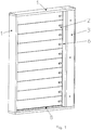
- the figures show a louvre flap which is designed as a combined fire protection and smoke extraction flap.
- the multi-leaf damper is intended for use in a line of an air conditioning and ventilation system (not shown) or a mechanical smoke extraction system (MRA).
- MRA mechanical smoke extraction system
- the louver flap comprises a frame 1 which forms a rectangular opening for the flow of a gaseous medium.
- the frame 1 consists of four frame elements which are connected to one another.
- the louver flap has ten rectangular slats 2.
- An auxiliary housing 3 is adjacent to the frame 1.
- a drive and a coupling element which can be displaced by means of a drive are arranged therein. All slats 2 are connected via the coupling element, so that when the coupling element is displaced, the position of all the slats 2 connected to one another via this coupling element can be changed equally.
- the coupling element can act directly or indirectly on the pivot axes 4 of the slats 2 coupled to one another. In such an embodiment, the slats 2 can run in the same direction, i. H. be pivoted in a common direction.
- each lamella 2 has two parallel to it Longitudinal edges 5 aligned with pivot axis 4 and two side edges 6 aligned orthogonally to their pivot axis 4.
- Each pivot axis 4 is arranged centrally between the longitudinal edges 5 of its lamella 2 and also centrally in relation to the thickness of its lamella 2.
- each of the two surfaces of the longitudinal edges 5 of each pair of adjacent slats 2 interacting in the closed position forms an inclined edge pair with respect to the orthogonal O, which is perpendicular to the plane E spanned by the respective slat 2, at an angle ⁇ of 30 ° aligned.
- the two surfaces of each pair of adjacent slats 2 face each other and, in the exemplary embodiment shown, are aligned parallel to one another.
- the height h 1 of the slat 2 increases in relation to the pivot axis 4 over the width of the slat 2 to the height h 2 of the slat 2 in the direction of pivoting (arrow V) from the closed position shown in the open position, not shown.
- the frame 1 has in its upper and in its lower area, which extend parallel to the upper and lower slats 2 in the closed position of the slats 2, a stop surface 7.
- Each stop surface 7 is part of a stop bar 8 mounted on the inside of the frame 1.
- Each stop surface 7 is aligned in such a way that it is aligned parallel to the surface of the longitudinal edge 5 of the adjacent lamella 2 when it is in its closed position, forming a pair of bevel edges is.
- Each of the two surfaces of all pairs of bevel edges each has a seal.
- a pair of inclined edges is understood to mean, on the one hand, the area of the longitudinal edges 5 of two adjacent slats 2 and, on the other hand, the area of a frame-side stop surface 7 and the longitudinal edge 5 of the adjacent slat 2.
- each inclined edge pair pointing upwards in the closed position has a seal designed as a cold seal 9, while a warm seal 10 is provided as a seal in the surface pointing downwards in the closed position.
- the strip-shaped heat seal 10 is arranged in a recess 11 in the surface or the frame-side stop surface 7 and protrudes only with a partial area from the recess 11.
- Each cold seal 9 arranged on the fins 2 is designed as a hollow profile seal with a round cross section and consists of a thermoplastic elastomer (TPE). Such an embodiment is for example in the 7 and 9 recognizable.
- TPE thermoplastic elastomer
- a web 12 is provided on its side facing the lamella 2 and extends over the entire length of the cold seal 9 and can be inserted into a groove 13 provided in the longitudinal edge 5 of the lamella 2 or in the stop surface 7.
- the web 12 has locking lugs 14 projecting laterally on both sides.
- the groove 13 is made in a recess 11 so that the hollow profile seal protrudes from the recess 11 only with a partial area.
- the frame 1 has a partial area 15 provided with a seal 9 in both areas, which in the closed position of the slats 2 extend parallel to the side edges 6 of the slats 2.
- This partial area 15 extends along the side edges 6 of the slats 2 in the closed position.
- the seal 9 is only glued in the partial area 15 and not - like the seal 10 in the two areas, which extend parallel to the upper and lower slats 2 in the closed position of the slats 2 - arranged in a recess 11.
- the width of the seal corresponds approximately to the thickness of the lamellae 2.
- the seal applied to the inside of the frame 2 is designed as a strip-shaped cold seal 9.
- This cold seal 9 applied here is based on a calcium-magnesium-silica chemistry.
- Such a cold seal 9 is available, for example, under the name Kerafix® 2000, Kerafix® 2000 also provides a warm seal.
- the cold seal 9 arranged in the areas of the frame 1, which in the closed position of the slats 2 extend parallel to the side edges 6 of the slats 2, is in each case strip-shaped, while that on each slat 2 and on the lower one Stop surface 7 arranged cold seal 9 is designed as a hollow cross-section seal having a round cross section
Landscapes
- Engineering & Computer Science (AREA)
- Chemical & Material Sciences (AREA)
- Combustion & Propulsion (AREA)
- Mechanical Engineering (AREA)
- General Engineering & Computer Science (AREA)
- Special Wing (AREA)
- Specific Sealing Or Ventilating Devices For Doors And Windows (AREA)
- Air-Flow Control Members (AREA)
Claims (12)
- Registre destiné à être utilisé dans une conduite d'une installation de climatisation et de ventilation ou d'une installation de désenfumage mécanique (MRA), comprenant d'une part un cadre (1), qui forme une ouverture rectangulaire pour l'écoulement d'un milieu gazeux, et d'autre part au moins deux lamelles de forme rectangulaire (2), dans lequel chaque lamelle (2) est montée de façon à pivoter autour d'un axe de pivotement respectif (4) entre sa position de fermeture et sa position d'ouverture dans le cadre (1), de préférence de concert avec au moins une autre lamelle (2), et chaque lamelle (2) présente d'une part deux côtés longitudinaux (5) orientés parallèlement à son axe de pivotement (4) et d'autre part deux côtés latéraux (6) orientés perpendiculairement à son axe de pivotement (4), dans lequel les axes de pivotement (4) sont disposés, de préférence au milieu, entre les côtés longitudinaux (5), et dans lequel au moins un des côtés longitudinaux (5) de lamelles voisines coopérant dans la position de fermeture présente un joint d'étanchéité (9, 10), dans lequel chacune des deux faces coopérant dans la position de fermeture des côtés longitudinaux (5) d'au moins une paire de lamelles voisines (2) est orientée, en formant une paire de côtés obliques par rapport à la perpendiculaire (O), qui est perpendiculaire au plan E défini par la lamelle respective (2), avec un angle α, qui se situe entre 10° et 60°, de préférence entre 25° et 40°, de préférence encore à 30°, et dans lequel dans la position de fermeture les deux faces de cette paire de lamelles voisines (2) sont orientées, en étant tournées l'une vers l'autre, en particulier parallèlement, de telle manière que la hauteur de la lamelle (2) par rapport à l'axe de pivotement (4) augmente sur la largeur de la lamelle (2) dans la direction du pivotement (V) de la position de fermeture à la position d'ouverture, que chacune des deux faces d'au moins une paire de côtés obliques présente au moins un joint d'étanchéité (9, 10), dans lequel ledit au moins un joint d'étanchéité est un joint d'étanchéité à chaud (10), de préférence en forme de bande, qui s'allonge sous l'action de la chaleur, dans lequel au moins un joint d'étanchéité (9, 10) est formé par un joint à froid (9), et dans lequel au moins chaque fois un joint d'étanchéité (9, 10) est disposé dans ladite au moins une paire de côtés obliques dans une direction vue perpendiculairement aux deux faces dans une région au moins partiellement opposée.
- Registre selon la revendication précédente, caractérisé en ce que le cadre (1) présente au moins dans une des deux régions, qui s'étendent dans la position de fermeture des lamelles (2) parallèlement à la lamelle supérieure et à la lamelle inférieure (2), une face de butée (7), qui est orientée de telle manière qu'elle soit orientée au moins environ parallèlement à la face du côté longitudinal (5) de la lamelle adjacente (2), lorsque celle-ci se trouve dans sa position de fermeture, en formant une paire de côtés obliques.
- Registre selon l'une quelconque des revendications précédentes, caractérisé en ce que le cadre (1) présente, dans au moins une des deux régions qui s'étendent dans la position de fermeture des lamelles (2) parallèlement aux côtés latéraux (6) des lamelles (2), une région partielle (15) munie d'un joint d'étanchéité (9, 10), qui s'étend le long de côtés latéraux (6) des lamelles (2) se trouvant dans la position de fermeture.
- Registre selon l'une quelconque des revendications précédentes, caractérisé en ce qu'au moins un joint d'étanchéité (9, 10) est disposé dans un évidement (11) et ne sort de préférence que par une région partielle hors de l'évidement (11).
- Registre selon l'une quelconque des revendications précédentes, caractérisé en ce qu'avec au moins une paire de côtés obliques au moins chaque fois un joint d'étanchéité (9, 10) est disposé dans une direction vue perpendiculairement aux deux faces dans des régions décalées l'une par rapport à l'autre.
- Registre selon l'une quelconque des revendications précédentes, caractérisé en ce qu'au moins un joint d'étanchéité à chaud (10) se compose d'un agent moussant à base stratifiée.
- Registre selon l'une quelconque des revendications précédentes, caractérisé en ce qu'au moins un joint d'étanchéité à froid (9) est réalisé par un joint d'étanchéité profilé creux, en particulier un joint d'étanchéité profilé creux présentant une section transversale ronde ou semi-circulaire.
- Registre selon l'une quelconque des revendications précédentes, caractérisé en ce qu'au moins un joint d'étanchéité à froid (9) se compose d'un élastomère thermoplastique (TPE).
- Registre selon l'une quelconque des revendications précédentes, caractérisé en ce qu'au moins un joint d'étanchéité à froid (9) présente, pour la fixation à la lamelle (2) sur son côté tourné vers la lamelle, ou à la face de butée (7) sur son côté tourné vers la face de butée (7), une nervure (12) s'étendant au moins sur une région partielle du joint d'étanchéité à froid (9), de préférence sur toute la longueur du joint d'étanchéité à froid (9), qui peut être introduite dans une rainure (13) prévue dans le côté longitudinal (5) et/ou le côté latéral (6) de la lamelle (2) ou dans la face de butée (7).
- Registre selon la revendication précédente, caractérisé en ce que la nervure (12) d'au moins un joint d'étanchéité à froid (9) présente au moins un ergot d'encliquetage saillant latéralement (14).
- Registre selon l'une quelconque des revendications précédentes, caractérisé en ce que le registre est réalisé sous forme de registre de désenfumage.
- Registre selon l'une quelconque des revendications précédentes, caractérisé en ce que le registre est réalisé sous forme de registre coupe-feu.
Applications Claiming Priority (1)
| Application Number | Priority Date | Filing Date | Title |
|---|---|---|---|
| DE202016105288.2U DE202016105288U1 (de) | 2016-09-22 | 2016-09-22 | Jalousieklappe für den Einsatz in einer Leitung einer klima- und raumlufttechnischen Anlage oder einer maschinellen Entrauchungsanlage |
Publications (3)
| Publication Number | Publication Date |
|---|---|
| EP3299740A1 EP3299740A1 (fr) | 2018-03-28 |
| EP3299740B1 EP3299740B1 (fr) | 2020-02-12 |
| EP3299740B9 true EP3299740B9 (fr) | 2020-07-22 |
Family
ID=58547356
Family Applications (1)
| Application Number | Title | Priority Date | Filing Date |
|---|---|---|---|
| EP17166224.0A Active EP3299740B9 (fr) | 2016-09-22 | 2017-04-12 | Registre destiné à être utilisé dans une conduite d'une installation de ventilation et de climatisation ou d'une installation de désenfumage mécanique |
Country Status (4)
| Country | Link |
|---|---|
| EP (1) | EP3299740B9 (fr) |
| DE (1) | DE202016105288U1 (fr) |
| DK (1) | DK3299740T5 (fr) |
| ES (1) | ES2791065T3 (fr) |
Cited By (1)
| Publication number | Priority date | Publication date | Assignee | Title |
|---|---|---|---|---|
| DE202023100853U1 (de) | 2023-02-23 | 2024-06-17 | Wildeboer Bauteile Gmbh | Brandschutz- und Entrauchungseinrichtung |
Families Citing this family (2)
| Publication number | Priority date | Publication date | Assignee | Title |
|---|---|---|---|---|
| DE102020122996A1 (de) | 2020-09-03 | 2022-03-03 | Vaillant Gmbh | Verfahren zum Abtauen einer der Umgebungsluft ausgesetzten Komponente und Vorrichtungen zur Durchführung des Verfahrens |
| CN114738893A (zh) * | 2022-04-27 | 2022-07-12 | 重庆交通职业学院 | 一种建筑通风结构 |
Family Cites Families (9)
| Publication number | Priority date | Publication date | Assignee | Title |
|---|---|---|---|---|
| DE2708109A1 (de) * | 1977-02-25 | 1978-08-31 | Schako Metallwarenfabrik | Feuerschutzklappe fuer kanaele von klima- und belueftungsanlagen |
| US4219185A (en) | 1978-05-16 | 1980-08-26 | Prefco Products, Inc. | Rotating blade fire damper |
| GB2212900A (en) | 1987-11-27 | 1989-08-02 | Flamgard | Fire damper |
| DE19947056A1 (de) | 1999-09-30 | 2001-04-05 | Janich Gmbh & Co | Regel- und Absperrklappe |
| FI118457B (fi) | 2005-12-13 | 2007-11-30 | Flaekt Woods Ab | Palopellin sulkuläppä |
| PL221312B1 (pl) | 2009-04-24 | 2016-03-31 | Mercor Spółka Akcyjna | Przegroda przeciwpożarowa |
| KR101080692B1 (ko) | 2011-06-21 | 2011-11-08 | (주)동아풍력 | 방화 댐퍼 |
| US9395098B2 (en) * | 2012-07-06 | 2016-07-19 | Ruskin Company | Damper blade seal system |
| US10222089B2 (en) * | 2014-10-28 | 2019-03-05 | T.A. Morrison & Co. Inc. | Damper with integrated blade stop |
-
2016
- 2016-09-22 DE DE202016105288.2U patent/DE202016105288U1/de active Active
-
2017
- 2017-04-12 ES ES17166224T patent/ES2791065T3/es active Active
- 2017-04-12 DK DK17166224.0T patent/DK3299740T5/da active
- 2017-04-12 EP EP17166224.0A patent/EP3299740B9/fr active Active
Cited By (2)
| Publication number | Priority date | Publication date | Assignee | Title |
|---|---|---|---|---|
| DE202023100853U1 (de) | 2023-02-23 | 2024-06-17 | Wildeboer Bauteile Gmbh | Brandschutz- und Entrauchungseinrichtung |
| EP4420739A1 (fr) | 2023-02-23 | 2024-08-28 | Wildeboer Bauteile GmbH | Dispositif de protection contre l'incendie et de désenfumage |
Also Published As
| Publication number | Publication date |
|---|---|
| DK3299740T5 (da) | 2020-08-31 |
| EP3299740B1 (fr) | 2020-02-12 |
| DE202016105288U1 (de) | 2018-01-09 |
| ES2791065T3 (es) | 2020-10-30 |
| DK3299740T3 (da) | 2020-05-11 |
| EP3299740A1 (fr) | 2018-03-28 |
Similar Documents
| Publication | Publication Date | Title |
|---|---|---|
| EP3299740B9 (fr) | Registre destiné à être utilisé dans une conduite d'une installation de ventilation et de climatisation ou d'une installation de désenfumage mécanique | |
| EP2778334B1 (fr) | Dispositif d'aération et vitrage | |
| EP1669110B1 (fr) | Dispositif d'étanchéité pour un rideau coupe-feu ou coupe-fumée | |
| WO2014072050A1 (fr) | Dispositif de recouvrement | |
| EP2813632B1 (fr) | Fenêtre de toit | |
| EP0396785B1 (fr) | Dispositif d'obturation d'installations de ventilation | |
| DE4008686A1 (de) | Brandschutzklappe | |
| DE102015014351A1 (de) | Belüftungselement für Fenster mit als Schikane wirkender Klappe | |
| EP3165702B1 (fr) | Element de fenêtre avec arrangement amelioré de ventilation forcée | |
| EP2893097B1 (fr) | Élément de construction pour l'isolation de façades et procédé de fabrication dudit élément de construction | |
| EP2778554A1 (fr) | Clapet de fermeture destiné à être utilisé dans une conduite d'une installation de ventilation ou d'une installation de désenfumage mécanique | |
| EP2947217A1 (fr) | Bloc d'isolation pour une fenêtre ou analogue | |
| DE202007005298U1 (de) | Tür, Metallkonstruktionsprofil für eine Zarge oder einen Rahmen für eine Tür oder ein Fenster | |
| EP3020890B1 (fr) | Volet de piscine | |
| EP4069930B1 (fr) | Porte enroulable de protection contre l'incendie | |
| EP3101363B1 (fr) | Clapet de fermeture destiné à être utilisé dans un canal d'une installation de ventilation ou d'une installation de désenfumage mécanique | |
| DE20109011U1 (de) | Tür mit einem oder zwei Flügel | |
| DE2431065A1 (de) | Verschlusseinrichtung | |
| DE202011106891U1 (de) | Lüftungseinsatz, insbesondere für Transformatorstationen | |
| DE602005000370T2 (de) | Verriegelungsvorrichtung für eine rolladenlamelle und rolladenlamelle mit einer solchen verriegelung | |
| DE102017006661B4 (de) | Brandschutzeinrichtung für Rohrleitungen mit einer schwimmenden Lagerung der Brandschutzklappen | |
| DE19652166C2 (de) | Abdichtvorrichtung für Rolladen | |
| DE202015102532U1 (de) | Absperrklappe für den Einsatz in einem Kanal einer raumlufttechnischen Anlage oder einer maschinellen Entrauchungsanlage | |
| EP3205376A1 (fr) | Clapet de protection incendie comprenant un matériau intumescent | |
| DE102006005750A1 (de) | Rollladen mit einer Mehrzahl gekoppelter Lamellen |
Legal Events
| Date | Code | Title | Description |
|---|---|---|---|
| PUAI | Public reference made under article 153(3) epc to a published international application that has entered the european phase |
Free format text: ORIGINAL CODE: 0009012 |
|
| STAA | Information on the status of an ep patent application or granted ep patent |
Free format text: STATUS: THE APPLICATION HAS BEEN PUBLISHED |
|
| AK | Designated contracting states |
Kind code of ref document: A1 Designated state(s): AL AT BE BG CH CY CZ DE DK EE ES FI FR GB GR HR HU IE IS IT LI LT LU LV MC MK MT NL NO PL PT RO RS SE SI SK SM TR |
|
| AX | Request for extension of the european patent |
Extension state: BA ME |
|
| STAA | Information on the status of an ep patent application or granted ep patent |
Free format text: STATUS: REQUEST FOR EXAMINATION WAS MADE |
|
| 17P | Request for examination filed |
Effective date: 20180928 |
|
| RBV | Designated contracting states (corrected) |
Designated state(s): AL AT BE BG CH CY CZ DE DK EE ES FI FR GB GR HR HU IE IS IT LI LT LU LV MC MK MT NL NO PL PT RO RS SE SI SK SM TR |
|
| TPAC | Observations filed by third parties |
Free format text: ORIGINAL CODE: EPIDOSNTIPA |
|
| GRAP | Despatch of communication of intention to grant a patent |
Free format text: ORIGINAL CODE: EPIDOSNIGR1 |
|
| STAA | Information on the status of an ep patent application or granted ep patent |
Free format text: STATUS: GRANT OF PATENT IS INTENDED |
|
| INTG | Intention to grant announced |
Effective date: 20190423 |
|
| TPAC | Observations filed by third parties |
Free format text: ORIGINAL CODE: EPIDOSNTIPA |
|
| TPAC | Observations filed by third parties |
Free format text: ORIGINAL CODE: EPIDOSNTIPA |
|
| TPAC | Observations filed by third parties |
Free format text: ORIGINAL CODE: EPIDOSNTIPA |
|
| GRAJ | Information related to disapproval of communication of intention to grant by the applicant or resumption of examination proceedings by the epo deleted |
Free format text: ORIGINAL CODE: EPIDOSDIGR1 |
|
| STAA | Information on the status of an ep patent application or granted ep patent |
Free format text: STATUS: REQUEST FOR EXAMINATION WAS MADE |
|
| GRAS | Grant fee paid |
Free format text: ORIGINAL CODE: EPIDOSNIGR3 |
|
| STAA | Information on the status of an ep patent application or granted ep patent |
Free format text: STATUS: GRANT OF PATENT IS INTENDED |
|
| GRAP | Despatch of communication of intention to grant a patent |
Free format text: ORIGINAL CODE: EPIDOSNIGR1 |
|
| INTC | Intention to grant announced (deleted) | ||
| INTG | Intention to grant announced |
Effective date: 20190925 |
|
| GRAA | (expected) grant |
Free format text: ORIGINAL CODE: 0009210 |
|
| STAA | Information on the status of an ep patent application or granted ep patent |
Free format text: STATUS: THE PATENT HAS BEEN GRANTED |
|
| AK | Designated contracting states |
Kind code of ref document: B1 Designated state(s): AL AT BE BG CH CY CZ DE DK EE ES FI FR GB GR HR HU IE IS IT LI LT LU LV MC MK MT NL NO PL PT RO RS SE SI SK SM TR |
|
| REG | Reference to a national code |
Ref country code: GB Ref legal event code: FG4D Free format text: NOT ENGLISH |
|
| REG | Reference to a national code |
Ref country code: CH Ref legal event code: EP |
|
| REG | Reference to a national code |
Ref country code: AT Ref legal event code: REF Ref document number: 1232634 Country of ref document: AT Kind code of ref document: T Effective date: 20200215 |
|
| REG | Reference to a national code |
Ref country code: DE Ref legal event code: R096 Ref document number: 502017003726 Country of ref document: DE |
|
| REG | Reference to a national code |
Ref country code: IE Ref legal event code: FG4D Free format text: LANGUAGE OF EP DOCUMENT: GERMAN |
|
| REG | Reference to a national code |
Ref country code: NL Ref legal event code: FP |
|
| REG | Reference to a national code |
Ref country code: DK Ref legal event code: T3 Effective date: 20200504 |
|
| REG | Reference to a national code |
Ref country code: CH Ref legal event code: PK Free format text: BERICHTIGUNG B9 |
|
| PG25 | Lapsed in a contracting state [announced via postgrant information from national office to epo] |
Ref country code: FI Free format text: LAPSE BECAUSE OF FAILURE TO SUBMIT A TRANSLATION OF THE DESCRIPTION OR TO PAY THE FEE WITHIN THE PRESCRIBED TIME-LIMIT Effective date: 20200212 Ref country code: RS Free format text: LAPSE BECAUSE OF FAILURE TO SUBMIT A TRANSLATION OF THE DESCRIPTION OR TO PAY THE FEE WITHIN THE PRESCRIBED TIME-LIMIT Effective date: 20200212 Ref country code: NO Free format text: LAPSE BECAUSE OF FAILURE TO SUBMIT A TRANSLATION OF THE DESCRIPTION OR TO PAY THE FEE WITHIN THE PRESCRIBED TIME-LIMIT Effective date: 20200512 |
|
| REG | Reference to a national code |
Ref country code: LT Ref legal event code: MG4D |
|
| PG25 | Lapsed in a contracting state [announced via postgrant information from national office to epo] |
Ref country code: HR Free format text: LAPSE BECAUSE OF FAILURE TO SUBMIT A TRANSLATION OF THE DESCRIPTION OR TO PAY THE FEE WITHIN THE PRESCRIBED TIME-LIMIT Effective date: 20200212 Ref country code: BG Free format text: LAPSE BECAUSE OF FAILURE TO SUBMIT A TRANSLATION OF THE DESCRIPTION OR TO PAY THE FEE WITHIN THE PRESCRIBED TIME-LIMIT Effective date: 20200512 Ref country code: LV Free format text: LAPSE BECAUSE OF FAILURE TO SUBMIT A TRANSLATION OF THE DESCRIPTION OR TO PAY THE FEE WITHIN THE PRESCRIBED TIME-LIMIT Effective date: 20200212 Ref country code: GR Free format text: LAPSE BECAUSE OF FAILURE TO SUBMIT A TRANSLATION OF THE DESCRIPTION OR TO PAY THE FEE WITHIN THE PRESCRIBED TIME-LIMIT Effective date: 20200513 Ref country code: SE Free format text: LAPSE BECAUSE OF FAILURE TO SUBMIT A TRANSLATION OF THE DESCRIPTION OR TO PAY THE FEE WITHIN THE PRESCRIBED TIME-LIMIT Effective date: 20200212 Ref country code: IS Free format text: LAPSE BECAUSE OF FAILURE TO SUBMIT A TRANSLATION OF THE DESCRIPTION OR TO PAY THE FEE WITHIN THE PRESCRIBED TIME-LIMIT Effective date: 20200612 |
|
| REG | Reference to a national code |
Ref country code: DK Ref legal event code: T5 Effective date: 20200826 |
|
| PG25 | Lapsed in a contracting state [announced via postgrant information from national office to epo] |
Ref country code: CZ Free format text: LAPSE BECAUSE OF FAILURE TO SUBMIT A TRANSLATION OF THE DESCRIPTION OR TO PAY THE FEE WITHIN THE PRESCRIBED TIME-LIMIT Effective date: 20200212 Ref country code: RO Free format text: LAPSE BECAUSE OF FAILURE TO SUBMIT A TRANSLATION OF THE DESCRIPTION OR TO PAY THE FEE WITHIN THE PRESCRIBED TIME-LIMIT Effective date: 20200212 Ref country code: SK Free format text: LAPSE BECAUSE OF FAILURE TO SUBMIT A TRANSLATION OF THE DESCRIPTION OR TO PAY THE FEE WITHIN THE PRESCRIBED TIME-LIMIT Effective date: 20200212 Ref country code: PT Free format text: LAPSE BECAUSE OF FAILURE TO SUBMIT A TRANSLATION OF THE DESCRIPTION OR TO PAY THE FEE WITHIN THE PRESCRIBED TIME-LIMIT Effective date: 20200705 Ref country code: EE Free format text: LAPSE BECAUSE OF FAILURE TO SUBMIT A TRANSLATION OF THE DESCRIPTION OR TO PAY THE FEE WITHIN THE PRESCRIBED TIME-LIMIT Effective date: 20200212 Ref country code: LT Free format text: LAPSE BECAUSE OF FAILURE TO SUBMIT A TRANSLATION OF THE DESCRIPTION OR TO PAY THE FEE WITHIN THE PRESCRIBED TIME-LIMIT Effective date: 20200212 Ref country code: SM Free format text: LAPSE BECAUSE OF FAILURE TO SUBMIT A TRANSLATION OF THE DESCRIPTION OR TO PAY THE FEE WITHIN THE PRESCRIBED TIME-LIMIT Effective date: 20200212 |
|
| REG | Reference to a national code |
Ref country code: ES Ref legal event code: FG2A Ref document number: 2791065 Country of ref document: ES Kind code of ref document: T3 Effective date: 20201030 |
|
| REG | Reference to a national code |
Ref country code: DE Ref legal event code: R097 Ref document number: 502017003726 Country of ref document: DE |
|
| PG25 | Lapsed in a contracting state [announced via postgrant information from national office to epo] |
Ref country code: MC Free format text: LAPSE BECAUSE OF FAILURE TO SUBMIT A TRANSLATION OF THE DESCRIPTION OR TO PAY THE FEE WITHIN THE PRESCRIBED TIME-LIMIT Effective date: 20200212 |
|
| PLBE | No opposition filed within time limit |
Free format text: ORIGINAL CODE: 0009261 |
|
| STAA | Information on the status of an ep patent application or granted ep patent |
Free format text: STATUS: NO OPPOSITION FILED WITHIN TIME LIMIT |
|
| 26N | No opposition filed |
Effective date: 20201113 |
|
| PG25 | Lapsed in a contracting state [announced via postgrant information from national office to epo] |
Ref country code: LU Free format text: LAPSE BECAUSE OF NON-PAYMENT OF DUE FEES Effective date: 20200412 |
|
| REG | Reference to a national code |
Ref country code: BE Ref legal event code: MM Effective date: 20200430 |
|
| PG25 | Lapsed in a contracting state [announced via postgrant information from national office to epo] |
Ref country code: PL Free format text: LAPSE BECAUSE OF FAILURE TO SUBMIT A TRANSLATION OF THE DESCRIPTION OR TO PAY THE FEE WITHIN THE PRESCRIBED TIME-LIMIT Effective date: 20200212 Ref country code: SI Free format text: LAPSE BECAUSE OF FAILURE TO SUBMIT A TRANSLATION OF THE DESCRIPTION OR TO PAY THE FEE WITHIN THE PRESCRIBED TIME-LIMIT Effective date: 20200212 Ref country code: BE Free format text: LAPSE BECAUSE OF NON-PAYMENT OF DUE FEES Effective date: 20200430 |
|
| PG25 | Lapsed in a contracting state [announced via postgrant information from national office to epo] |
Ref country code: IE Free format text: LAPSE BECAUSE OF NON-PAYMENT OF DUE FEES Effective date: 20200412 |
|
| PG25 | Lapsed in a contracting state [announced via postgrant information from national office to epo] |
Ref country code: MT Free format text: LAPSE BECAUSE OF FAILURE TO SUBMIT A TRANSLATION OF THE DESCRIPTION OR TO PAY THE FEE WITHIN THE PRESCRIBED TIME-LIMIT Effective date: 20200212 Ref country code: CY Free format text: LAPSE BECAUSE OF FAILURE TO SUBMIT A TRANSLATION OF THE DESCRIPTION OR TO PAY THE FEE WITHIN THE PRESCRIBED TIME-LIMIT Effective date: 20200212 |
|
| PG25 | Lapsed in a contracting state [announced via postgrant information from national office to epo] |
Ref country code: MK Free format text: LAPSE BECAUSE OF FAILURE TO SUBMIT A TRANSLATION OF THE DESCRIPTION OR TO PAY THE FEE WITHIN THE PRESCRIBED TIME-LIMIT Effective date: 20200212 Ref country code: AL Free format text: LAPSE BECAUSE OF FAILURE TO SUBMIT A TRANSLATION OF THE DESCRIPTION OR TO PAY THE FEE WITHIN THE PRESCRIBED TIME-LIMIT Effective date: 20200212 |
|
| P01 | Opt-out of the competence of the unified patent court (upc) registered |
Effective date: 20230517 |
|
| REG | Reference to a national code |
Ref country code: DE Ref legal event code: R081 Ref document number: 502017003726 Country of ref document: DE Owner name: TROX SE, DE Free format text: FORMER OWNER: TROX GMBH, 47506 NEUKIRCHEN-VLUYN, DE |
|
| PGFP | Annual fee paid to national office [announced via postgrant information from national office to epo] |
Ref country code: NL Payment date: 20250422 Year of fee payment: 9 |
|
| PGFP | Annual fee paid to national office [announced via postgrant information from national office to epo] |
Ref country code: DE Payment date: 20250306 Year of fee payment: 9 |
|
| PGFP | Annual fee paid to national office [announced via postgrant information from national office to epo] |
Ref country code: ES Payment date: 20250519 Year of fee payment: 9 Ref country code: DK Payment date: 20250423 Year of fee payment: 9 |
|
| PGFP | Annual fee paid to national office [announced via postgrant information from national office to epo] |
Ref country code: IT Payment date: 20250430 Year of fee payment: 9 |
|
| PGFP | Annual fee paid to national office [announced via postgrant information from national office to epo] |
Ref country code: FR Payment date: 20250422 Year of fee payment: 9 |
|
| PGFP | Annual fee paid to national office [announced via postgrant information from national office to epo] |
Ref country code: CH Payment date: 20250501 Year of fee payment: 9 |
|
| PGFP | Annual fee paid to national office [announced via postgrant information from national office to epo] |
Ref country code: AT Payment date: 20250416 Year of fee payment: 9 |
|
| PGFP | Annual fee paid to national office [announced via postgrant information from national office to epo] |
Ref country code: TR Payment date: 20250404 Year of fee payment: 9 |
|
| PGFP | Annual fee paid to national office [announced via postgrant information from national office to epo] |
Ref country code: GB Payment date: 20260327 Year of fee payment: 10 |