EP3205376A1 - Clapet de protection incendie comprenant un matériau intumescent - Google Patents
Clapet de protection incendie comprenant un matériau intumescent Download PDFInfo
- Publication number
- EP3205376A1 EP3205376A1 EP17000068.1A EP17000068A EP3205376A1 EP 3205376 A1 EP3205376 A1 EP 3205376A1 EP 17000068 A EP17000068 A EP 17000068A EP 3205376 A1 EP3205376 A1 EP 3205376A1
- Authority
- EP
- European Patent Office
- Prior art keywords
- wing
- flap
- fire damper
- intumescent material
- intumescent
- Prior art date
- Legal status (The legal status is an assumption and is not a legal conclusion. Google has not performed a legal analysis and makes no representation as to the accuracy of the status listed.)
- Withdrawn
Links
Images




Classifications
-
- A—HUMAN NECESSITIES
- A62—LIFE-SAVING; FIRE-FIGHTING
- A62C—FIRE-FIGHTING
- A62C2/00—Fire prevention or containment
- A62C2/06—Physical fire-barriers
- A62C2/065—Physical fire-barriers having as the main closure device materials, whose characteristics undergo an irreversible change under high temperatures, e.g. intumescent
-
- A—HUMAN NECESSITIES
- A62—LIFE-SAVING; FIRE-FIGHTING
- A62C—FIRE-FIGHTING
- A62C2/00—Fire prevention or containment
- A62C2/06—Physical fire-barriers
- A62C2/12—Hinged dampers
- A62C2/14—Hinged dampers with two or more blades
Definitions
- the invention relates to a fire damper with an intumescent under fire action and under the influence of heat material (intumescent material).
- Intumescent building materials are also called "insulating layers". In Germany intumescent building materials and components containing them are subject to approval.
- Fire dampers are installed in walls and / or ceilings of buildings in the form of overflow flaps. This means that at the left boundary of the wall can be a room and at the right boundary of the wall and in the wall between a built-in as overflow flap fire damper is installed.
- Another important installation case for the fire damper according to the invention is the installation of the fire damper in an existing ventilation duct, which leads, for example, to the outside.
- the fire damper according to the invention is suitable.
- Such a material is called intumescent material. Because of the pivotable about a pivot axis mounted flap element, there is the disadvantage that such a fire protection device is subject to maintenance.
- the invention is therefore based on the object, a fire damper of the type mentioned in such a way that can be dispensed with a mechanical pivotal mounting of flap elements, thus the entire fire damper is maintenance-free and corresponds to said DIN standard.
- a feature of the invention is that the intumescent material foaming under heat attack forms a pivot drive for at least one wing part arranged on the flap element.
- a single wing flap it is sufficient for the realization of a single wing flap to arrange only a single, pivotally arranged on one side of a base plate wing part, which pivots under the action of the expanding intumescent material along a plastically deformable bending edge.
- the size of the wing part then corresponds approximately to the area of the base part, so that the wing part approximately covers the base plate.
- a wing part is arranged on both sides of a base plate.
- two opposing wing flaps present, which form with their undersides in the direction of the base plate a receiving chamber for the intumescent material and pivot up against each other.
- the flap element of the fire damper consists of two mirror-symmetrically mounted against each other fastened, sheet-like wing flaps, each wing flap consists of two overlapping with respect to their free ends, flap-like wing parts, which between them a receiving chamber for receiving an approximately plate-like intumescence -Materials form and which are pivotally connected via each end-side bending edges with the base plate of the respective wing flap.
- the pivot axis of the individual wing parts which in pairs form a wing flap, is formed as a plastic, one-time bendable bending edge. It therefore lacks an axle-mounted pivot axis.
- the swivel drive for the wing parts is done by the foaming of the intumescent material.
- the wing flap consists of a thin flap-like sheet metal part and the bending edge advantageously has bend-facilitating slots.
- the wing parts are connected only in certain web areas in the space between the bend-facilitating slots with the base plate of the wing flap, so as to allow easy flexibility.
- the wing flaps pivot over a plastic bending of the arranged there in the web area metallic sheet material under the action of the intumescent material.
- the flap element unfolds with the two - broadside on broadside - interconnected wing flaps such that the two wing parts on the respective wing flap directed against each other swing open and fill the interior of the tube housing of the fire damper sealed.
- the wing flaps are driven by an intumescent material pivotally, there is the advantage that even at a negative pressure of more than 300 Pascal there is no risk that the internal cross section of the tube housing filling, foamed intumescent material is removed.
- the flap element with its two mirror-symmetrically attached to the broad side wing flaps thus ensures a stationary storage and Eincroung of the foamed intumescent material, without the risk that the foamed intumescent material is removed in case of fire by the resulting negative pressure flow. It is protected and covered on both sides by the pivoted-up metal plates of the wing parts against the incoming air flow.
- each wing flap consists of overlapping sheet-like wing parts in the middle region, which each form the plastically deformable bending edge on the outside in the direction of a base plate and form a receiving chamber for the plate-shaped intumescent material in connection with the base plate.
- the overlap of the individual wing parts is that they drive each other when pivoting in the pivoting direction, which means that the stored in the receiving chamber intumescent material first swings the wing part when foaming the intumescent material and thereby entrains the opposite wing part and in supported his Aufschwenkamba.
- the two wing parts which overlap at the free ends thus assist one another when pivoting about the plastically deformable bending edges which are respectively arranged opposite one another and parallel to one another.
- the two, overlapping wing portions of the respective wing flap form the upper boundary of a receiving chamber, in which the Intumeszenz material is included.
- a false foaming is avoided in an undesirable direction during foaming of the intumescent material, because the two wing parts close the receiving chamber upwards and thus force the intumescent intumescent material to expand against the respective pivotal parts of the respective wing part so the two wing parts directed against each other to swing their plastic bending edges.
- each wing flap which in turn consists of two wing parts in turn, is associated with an additional drive element, which under the action of an intumescent intumescent material forms a radial displacement drive for one wing flap each.
- Such a drive element can below the respective wing flap, d. H. be arranged below the base plate of the respective wing flap and ensures that the respective wing flap accelerated under the action of this drive element in the radial direction is pushed onto the inner cross section of the tubular housing, so as to allow an accelerated fire completion of the interior of the tubular housing.
- this additional drive element performs an additional drive in the radial direction of the tubular housing and it is particularly preferred if the drive element is also designed as a wing flap, which similar to the other wing flaps an inner receiving chamber for receiving formed by intumescent material and the intumescent material there foaming also deforms radially outward side wing parts under plastic deformation in the region of the bending edges, so as to push the wing flap lying on it radially outwards, thereby allowing a faster fire seal the interior of the tube housing ,
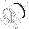
- a fire damper 1 which consists essentially of a metallic pipe housing 2, in whose axially spaced pipe sections two different, arranged on the outer circumference Abdichtringe are arranged.
- the one sealing ring 3 is designed as a so-called cold seal and provides a seal of the tubular housing 2 in a passage cross section of a wall, while the oppositely arranged sealing ring 4 is formed as a hot seal and consists essentially of a ring seal, which foams under heat.
- FIG. 1 registered that an air flow through the tube housing 2 in the direction of arrow 5 takes place.
- the air flow can also run in the opposite direction to the arrow 5.
- the tubular housing 2 forms a tubular interior 7, which is completely closed by a centrally installed flap element 6 in case of fire.
- a cylindrical cross section of the tubular housing may also other cross sections, such. B. a square cross-section can be used.
- the flap member 6 consists of two flat side-to-flat side interconnected wing flaps 8, 9, which are preferably made of a sheet material having a thickness of z. B. 0.6 mm.
- the one wing flap 8 is identical to the wing flap 9 and the two wing flaps 8, 9 beyond a parting line 10 are arranged mirror-symmetrically to each other, it is basically sufficient to explain only the function of a single wing flap 8 with its wing parts 11 and 12, because the other wing flap 9 with its wing parts 13, 14 identically identical.
- the two wing flaps 8, 9 each have a base plate 16, 17, and the two adjoining base plates 16, 17 form over their entire surface a parting line 15 which is impermeable to air.
- the two adjoining base plates 16, 17 of the wing flaps 8, 9 are interconnected, for example, by an adhesive or by other mechanical connection means.
- FIGS. 2 to 4 show that each wing flap 8, 9 consists of wing parts 11, 12 and 13, 14 which overlap with their free ends. This is especially out FIG. 5 refer to.
- each wing flap 8, 9 continues with a short vertical web upwards, wherein the height of the web is about 3 mm.
- the wing parts 11, 12 form the upper cover of a self-contained receiving chamber 25, which is open only to the front side to the outside.
- the receiving chamber 25 is formed at the top by the two overlapping wing parts 11, 12 and the bottom by the base plate 16, wherein the lateral webs in FIG. 5 not provided with reference numerals.
- a plate-shaped intumescent material 27 is inserted.
- FIG. 6 shows the partially swung-out state of the wing parts 11-14, where it can be seen that the two receiving chambers 25, 26 have multiplied under the action of the intumescent material 27 in volume and the intumescent material ensures that the wing parts 11, 12 in the arrow directions 20, 20 'and the wing parts 13, 14 in the direction of arrows 21, 21' pivot against each other. There is a plastic deformation in the region of the oppositely arranged bending edges 18, 28 and 19, 29 instead.
- FIG. 6 the advantage of the metallic flap element with the two plastically bendable, sheet metal flap-like wing flaps 8, 9 can be seen.
- the metallic flap elements cover the foamed intumescent material 27 against a flow of air flowing in the direction of arrow 5 and in the opposite direction. Thus, it is prevented that the foamed intumescent material 27 is discharged from the interior 7 of the tube housing 2.
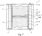
- FIG. 7 is the fully swung out state of the wing parts 11-14 shown.
- the initial state 30 was increased in relation to the volume of the receiving chambers 25, 26 in a compared to the greatly expanded state 30 '.
- the foamed intumescent material 27 has ensured that the wing parts 11-14 fill the complete cross section.
- intumescent intumescent material in fire dampers could not always be guaranteed in the prior art that the intumescent material rests space filling the inner circumference of the tube housing.
- the invention provides that the intumescent material is the drive means for pivoting the wing parts 11-14, so that it is not necessary for the solution that the intumescent intumescent material the complete interior 7 of the tubular housing. 2 closes. This is done by the wing flaps 8, 9 with the plastically bendable in the pivot axis wing parts 11-14.
- FIG. 8 shows the top view of the pipe cross section in the interior 7 filling wing parts 12, 14. Again, it can be seen that there is a plastic deformation of the pivot axes of the connecting webs 23 to the respective base plate 16, 17 subsequent wing parts 12, 14.
- FIGS. 9 and 10 show an example of installation of the fire damper 1 in a wall or ceiling 34th
- FIG. 10 shows the side view of the same installation example.
- the beads 31 thus form the stop surfaces 32 for the wing parts 11-14.
- FIGS. 11 and 12 show an expanded embodiment of a flap element 6 ', wherein the drawing simplification is shown because of only one half of the flap element 6'. It is merely the upper wing flap 8 'is shown and it is not shown that beyond the line of symmetry 35 attaches the other, oppositely directed wing flap 9'. This is - not shown - assigned the same drive element.
- the wing flap 8 ' consists of the same parts as the previously discussed wing flap 8, except that the base plate 16 of the wing flap 8' is not directly on the base plate 17 of the opposing wing flap 9 'is applied, but there is another drive element beyond the line of symmetry 35 is arranged.
- the drive element is preferably designed as a wing flap 38 and forms with its plate-shaped base plate 41 and the laterally adjoining plastically bendable webs a self-contained space which is formed as a receiving chamber 36 for an intumescent material 27.
- the upper end of the receiving chamber 36 is formed by two oppositely directed wing parts 39, 40, either with their free ends overlap or the free ends take a mutual distance from each other, as in FIG. 11 is shown.
- the wing parts 39, 40 form the drive elements for the radial advance of the wing flap 8 'in the direction of arrow 37 in case of fire.
- the inner flap flap 38 is hit by the heat source with the intumescent material arranged there in the receiving chamber 36.
- the material contained there in the receiving chamber 36 will foam in the direction of arrow 37 and thereby pivot the two wing parts 39, 40 under elastic deformation of their bending edges to the outside, as shown in FIG. 12 is shown. They thus stand up and at the same time support themselves on the underside of the base plate 16 of the wing part 8 'in order to displace it in the radial direction (arrow direction 37) outwards in the direction of the inner circumference of the tubular housing 2.
Landscapes
- Health & Medical Sciences (AREA)
- Public Health (AREA)
- Business, Economics & Management (AREA)
- Emergency Management (AREA)
- Air-Flow Control Members (AREA)
Applications Claiming Priority (1)
| Application Number | Priority Date | Filing Date | Title |
|---|---|---|---|
| DE102016001512.8A DE102016001512B4 (de) | 2016-02-10 | 2016-02-10 | Brandschutzklappe mit Intumeszenz-Material |
Publications (1)
| Publication Number | Publication Date |
|---|---|
| EP3205376A1 true EP3205376A1 (fr) | 2017-08-16 |
Family
ID=57821793
Family Applications (1)
| Application Number | Title | Priority Date | Filing Date |
|---|---|---|---|
| EP17000068.1A Withdrawn EP3205376A1 (fr) | 2016-02-10 | 2017-01-13 | Clapet de protection incendie comprenant un matériau intumescent |
Country Status (2)
| Country | Link |
|---|---|
| EP (1) | EP3205376A1 (fr) |
| DE (1) | DE102016001512B4 (fr) |
Cited By (1)
| Publication number | Priority date | Publication date | Assignee | Title |
|---|---|---|---|---|
| DE202017104431U1 (de) * | 2017-07-25 | 2018-10-26 | Werner Wildeboer | Brandschutztechnische Überströmklappe |
Citations (6)
| Publication number | Priority date | Publication date | Assignee | Title |
|---|---|---|---|---|
| FR2305202A1 (fr) * | 1975-03-28 | 1976-10-22 | Wache Hubert | Dispositif coupe-feu pour conduits |
| DE19627987A1 (de) * | 1995-07-12 | 1997-01-16 | Gert Bartholomaeus | Brandschutzeinrichtung zur Abschottung einer Lüftungsrohrleitung |
| EP0824940A2 (fr) * | 1996-08-23 | 1998-02-25 | Gert Bartholomäus | Clapet coupe-feu |
| DE19938498A1 (de) * | 1999-08-13 | 2001-03-08 | Werner Wildeboer | Brandschutz-Absperrung für eine lufttechnische Anlage eines Gebäudes mit zumindestens einem einen Luftstrom führenden Lüftungskanal |
| DE10043774A1 (de) | 2000-09-06 | 2002-04-04 | Guenter Schulte | Brandschutzeinrichtung |
| AT411965B (de) | 1999-11-02 | 2004-08-26 | Kamleithner Maly Uta Ing Mag | Brandschutz-einrichtung |
Family Cites Families (2)
| Publication number | Priority date | Publication date | Assignee | Title |
|---|---|---|---|---|
| DE19643854B4 (de) | 1996-10-30 | 2004-07-15 | Bartholomäus, Gert | Brandschutzeinrichtung für Rohrleitungen |
| GB2499818B (en) | 2012-02-29 | 2015-09-02 | Bsb Engineering Services Ltd | Damper blade |
-
2016
- 2016-02-10 DE DE102016001512.8A patent/DE102016001512B4/de active Active
-
2017
- 2017-01-13 EP EP17000068.1A patent/EP3205376A1/fr not_active Withdrawn
Patent Citations (6)
| Publication number | Priority date | Publication date | Assignee | Title |
|---|---|---|---|---|
| FR2305202A1 (fr) * | 1975-03-28 | 1976-10-22 | Wache Hubert | Dispositif coupe-feu pour conduits |
| DE19627987A1 (de) * | 1995-07-12 | 1997-01-16 | Gert Bartholomaeus | Brandschutzeinrichtung zur Abschottung einer Lüftungsrohrleitung |
| EP0824940A2 (fr) * | 1996-08-23 | 1998-02-25 | Gert Bartholomäus | Clapet coupe-feu |
| DE19938498A1 (de) * | 1999-08-13 | 2001-03-08 | Werner Wildeboer | Brandschutz-Absperrung für eine lufttechnische Anlage eines Gebäudes mit zumindestens einem einen Luftstrom führenden Lüftungskanal |
| AT411965B (de) | 1999-11-02 | 2004-08-26 | Kamleithner Maly Uta Ing Mag | Brandschutz-einrichtung |
| DE10043774A1 (de) | 2000-09-06 | 2002-04-04 | Guenter Schulte | Brandschutzeinrichtung |
Cited By (1)
| Publication number | Priority date | Publication date | Assignee | Title |
|---|---|---|---|---|
| DE202017104431U1 (de) * | 2017-07-25 | 2018-10-26 | Werner Wildeboer | Brandschutztechnische Überströmklappe |
Also Published As
| Publication number | Publication date |
|---|---|
| DE102016001512A1 (de) | 2017-08-10 |
| DE102016001512B4 (de) | 2024-12-05 |
Similar Documents
| Publication | Publication Date | Title |
|---|---|---|
| DE19600369C2 (de) | Brandschutzeinrichtung zur Abschottung einer Rohrleitung | |
| EP0717165B2 (fr) | Ossature de profiles métalliques ignifuges pour fenêtres, portes, façades ou toits vitrés | |
| DE2103966A1 (de) | Luftkammerkonstruktion | |
| AT506329A2 (de) | Feuerschutzkonstruktion | |
| AT513226A1 (de) | Brandschutzeinrichtung | |
| EP0512414A2 (fr) | Clapet coupe-feu | |
| DE19643854B4 (de) | Brandschutzeinrichtung für Rohrleitungen | |
| DE10134839A1 (de) | Einrichtung zum rauch- und feuerbeständigen Verschliessen eines Wand- oder Deckendurchbruchs | |
| DE19938498B4 (de) | Brandschutz-Absperrung für eine lufttechnische Anlage eines Gebäudes mit zumindestens einem einen Luftstrom führenden Lüftungskanal | |
| EP3205376A1 (fr) | Clapet de protection incendie comprenant un matériau intumescent | |
| EP3280019A1 (fr) | Boitier d'installation pour installation electrique | |
| EP3299740B9 (fr) | Registre destiné à être utilisé dans une conduite d'une installation de ventilation et de climatisation ou d'une installation de désenfumage mécanique | |
| DE102015014351A1 (de) | Belüftungselement für Fenster mit als Schikane wirkender Klappe | |
| DE202012104425U1 (de) | Einbauelement für eine Brandschutzklappe sowie Brandschutzklappe mit einem Einbauelement | |
| DE2708109A1 (de) | Feuerschutzklappe fuer kanaele von klima- und belueftungsanlagen | |
| EP3207959B1 (fr) | Barrière coupe-feu pour conduites comprenant des volets de fermeture segmentés | |
| DE3140043C2 (de) | Brandschutzklappe | |
| CH675211A5 (en) | Fire shutter for ventilation or drain duct | |
| DE8808393U1 (de) | Vorrichtung zum automatischen Verschließen eines Rohres | |
| DE2914467A1 (de) | Stahlglas-feuerschutztuer | |
| DE102017006661B4 (de) | Brandschutzeinrichtung für Rohrleitungen mit einer schwimmenden Lagerung der Brandschutzklappen | |
| EP2034120B1 (fr) | Equipement pour fermetures coupe-feu | |
| EP2772283A2 (fr) | Clapet anti-feu destiné à empêcher la transmission de feu et de fumée dans un boîtier tubulaire | |
| DE102004047093A1 (de) | Absperrvorrichtung zum Brandverschluss eines Rohres oder Kanals | |
| DE202004003276U1 (de) | Brandschutzventil mit Kaltrauchsperre |
Legal Events
| Date | Code | Title | Description |
|---|---|---|---|
| PUAI | Public reference made under article 153(3) epc to a published international application that has entered the european phase |
Free format text: ORIGINAL CODE: 0009012 |
|
| STAA | Information on the status of an ep patent application or granted ep patent |
Free format text: STATUS: THE APPLICATION HAS BEEN PUBLISHED |
|
| AK | Designated contracting states |
Kind code of ref document: A1 Designated state(s): AL AT BE BG CH CY CZ DE DK EE ES FI FR GB GR HR HU IE IS IT LI LT LU LV MC MK MT NL NO PL PT RO RS SE SI SK SM TR |
|
| AX | Request for extension of the european patent |
Extension state: BA ME |
|
| STAA | Information on the status of an ep patent application or granted ep patent |
Free format text: STATUS: THE APPLICATION IS DEEMED TO BE WITHDRAWN |
|
| 18D | Application deemed to be withdrawn |
Effective date: 20180217 |