EP3300169B1 - Radarabdeckung und verfahren zur herstellung der radarabdeckung - Google Patents
Radarabdeckung und verfahren zur herstellung der radarabdeckung Download PDFInfo
- Publication number
- EP3300169B1 EP3300169B1 EP17192372.5A EP17192372A EP3300169B1 EP 3300169 B1 EP3300169 B1 EP 3300169B1 EP 17192372 A EP17192372 A EP 17192372A EP 3300169 B1 EP3300169 B1 EP 3300169B1
- Authority
- EP
- European Patent Office
- Prior art keywords
- layer
- bright
- transparent
- emblem
- base portion
- Prior art date
- Legal status (The legal status is an assumption and is not a legal conclusion. Google has not performed a legal analysis and makes no representation as to the accuracy of the status listed.)
- Active
Links
- 238000004519 manufacturing process Methods 0.000 title claims description 17
- 239000000463 material Substances 0.000 claims description 12
- NJPPVKZQTLUDBO-UHFFFAOYSA-N novaluron Chemical compound C1=C(Cl)C(OC(F)(F)C(OC(F)(F)F)F)=CC=C1NC(=O)NC(=O)C1=C(F)C=CC=C1F NJPPVKZQTLUDBO-UHFFFAOYSA-N 0.000 claims description 7
- 230000015572 biosynthetic process Effects 0.000 claims description 6
- 229910052751 metal Inorganic materials 0.000 claims description 6
- 239000002184 metal Substances 0.000 claims description 6
- 230000000149 penetrating effect Effects 0.000 claims description 6
- 238000000034 method Methods 0.000 description 18
- 239000011248 coating agent Substances 0.000 description 7
- 238000000576 coating method Methods 0.000 description 7
- 229920003002 synthetic resin Polymers 0.000 description 6
- 239000000057 synthetic resin Substances 0.000 description 6
- 238000001746 injection moulding Methods 0.000 description 5
- 238000011282 treatment Methods 0.000 description 5
- 229920000515 polycarbonate Polymers 0.000 description 4
- 239000004417 polycarbonate Substances 0.000 description 4
- 239000005020 polyethylene terephthalate Substances 0.000 description 4
- 229920000139 polyethylene terephthalate Polymers 0.000 description 4
- 239000011347 resin Substances 0.000 description 4
- 229920005989 resin Polymers 0.000 description 4
- WSFSSNUMVMOOMR-UHFFFAOYSA-N Formaldehyde Chemical compound O=C WSFSSNUMVMOOMR-UHFFFAOYSA-N 0.000 description 3
- YXFVVABEGXRONW-UHFFFAOYSA-N Toluene Chemical compound CC1=CC=CC=C1 YXFVVABEGXRONW-UHFFFAOYSA-N 0.000 description 3
- 229910052782 aluminium Inorganic materials 0.000 description 3
- XAGFODPZIPBFFR-UHFFFAOYSA-N aluminium Chemical compound [Al] XAGFODPZIPBFFR-UHFFFAOYSA-N 0.000 description 3
- 229910052738 indium Inorganic materials 0.000 description 3
- APFVFJFRJDLVQX-UHFFFAOYSA-N indium atom Chemical compound [In] APFVFJFRJDLVQX-UHFFFAOYSA-N 0.000 description 3
- -1 polyethylene terephthalate Polymers 0.000 description 3
- YNQLUTRBYVCPMQ-UHFFFAOYSA-N Ethylbenzene Chemical compound CCC1=CC=CC=C1 YNQLUTRBYVCPMQ-UHFFFAOYSA-N 0.000 description 2
- LRHPLDYGYMQRHN-UHFFFAOYSA-N N-Butanol Chemical compound CCCCO LRHPLDYGYMQRHN-UHFFFAOYSA-N 0.000 description 2
- 229920002877 acrylic styrene acrylonitrile Polymers 0.000 description 2
- 239000004676 acrylonitrile butadiene styrene Substances 0.000 description 2
- 229920001923 acrylonitrile-ethylene-styrene Polymers 0.000 description 2
- DKPFZGUDAPQIHT-UHFFFAOYSA-N butyl acetate Chemical compound CCCCOC(C)=O DKPFZGUDAPQIHT-UHFFFAOYSA-N 0.000 description 2
- 238000007334 copolymerization reaction Methods 0.000 description 2
- JHIVVAPYMSGYDF-UHFFFAOYSA-N cyclohexanone Chemical compound O=C1CCCCC1 JHIVVAPYMSGYDF-UHFFFAOYSA-N 0.000 description 2
- 238000000465 moulding Methods 0.000 description 2
- 229920003229 poly(methyl methacrylate) Polymers 0.000 description 2
- 229920001707 polybutylene terephthalate Polymers 0.000 description 2
- 239000004926 polymethyl methacrylate Substances 0.000 description 2
- 238000004544 sputter deposition Methods 0.000 description 2
- 239000010409 thin film Substances 0.000 description 2
- 239000004925 Acrylic resin Substances 0.000 description 1
- 229920000178 Acrylic resin Polymers 0.000 description 1
- YAAQEISEHDUIFO-UHFFFAOYSA-N C=CC#N.OC(=O)C=CC=CC1=CC=CC=C1 Chemical compound C=CC#N.OC(=O)C=CC=CC1=CC=CC=C1 YAAQEISEHDUIFO-UHFFFAOYSA-N 0.000 description 1
- JOYRKODLDBILNP-UHFFFAOYSA-N Ethyl urethane Chemical compound CCOC(N)=O JOYRKODLDBILNP-UHFFFAOYSA-N 0.000 description 1
- VVQNEPGJFQJSBK-UHFFFAOYSA-N Methyl methacrylate Chemical compound COC(=O)C(C)=C VVQNEPGJFQJSBK-UHFFFAOYSA-N 0.000 description 1
- CTQNGGLPUBDAKN-UHFFFAOYSA-N O-Xylene Chemical compound CC1=CC=CC=C1C CTQNGGLPUBDAKN-UHFFFAOYSA-N 0.000 description 1
- 239000000654 additive Substances 0.000 description 1
- 230000005540 biological transmission Effects 0.000 description 1
- 238000004364 calculation method Methods 0.000 description 1
- 210000000078 claw Anatomy 0.000 description 1
- 239000000805 composite resin Substances 0.000 description 1
- 239000000470 constituent Substances 0.000 description 1
- 238000001035 drying Methods 0.000 description 1
- 238000005516 engineering process Methods 0.000 description 1
- 239000010408 film Substances 0.000 description 1
- 238000012986 modification Methods 0.000 description 1
- 230000004048 modification Effects 0.000 description 1
- 239000003960 organic solvent Substances 0.000 description 1
- 238000007747 plating Methods 0.000 description 1
- 230000002265 prevention Effects 0.000 description 1
- 239000012780 transparent material Substances 0.000 description 1
- 238000001771 vacuum deposition Methods 0.000 description 1
- 238000009423 ventilation Methods 0.000 description 1
- 239000008096 xylene Substances 0.000 description 1
Images

Classifications
-
- H—ELECTRICITY
- H01—ELECTRIC ELEMENTS
- H01Q—ANTENNAS, i.e. RADIO AERIALS
- H01Q1/00—Details of, or arrangements associated with, antennas
- H01Q1/42—Housings not intimately mechanically associated with radiating elements, e.g. radome
-
- B—PERFORMING OPERATIONS; TRANSPORTING
- B60—VEHICLES IN GENERAL
- B60R—VEHICLES, VEHICLE FITTINGS, OR VEHICLE PARTS, NOT OTHERWISE PROVIDED FOR
- B60R13/00—Elements for body-finishing, identifying, or decorating; Arrangements or adaptations for advertising purposes
- B60R13/005—Manufacturers' emblems, name plates, bonnet ornaments, mascots or the like; Mounting means therefor
-
- C—CHEMISTRY; METALLURGY
- C23—COATING METALLIC MATERIAL; COATING MATERIAL WITH METALLIC MATERIAL; CHEMICAL SURFACE TREATMENT; DIFFUSION TREATMENT OF METALLIC MATERIAL; COATING BY VACUUM EVAPORATION, BY SPUTTERING, BY ION IMPLANTATION OR BY CHEMICAL VAPOUR DEPOSITION, IN GENERAL; INHIBITING CORROSION OF METALLIC MATERIAL OR INCRUSTATION IN GENERAL
- C23C—COATING METALLIC MATERIAL; COATING MATERIAL WITH METALLIC MATERIAL; SURFACE TREATMENT OF METALLIC MATERIAL BY DIFFUSION INTO THE SURFACE, BY CHEMICAL CONVERSION OR SUBSTITUTION; COATING BY VACUUM EVAPORATION, BY SPUTTERING, BY ION IMPLANTATION OR BY CHEMICAL VAPOUR DEPOSITION, IN GENERAL
- C23C14/00—Coating by vacuum evaporation, by sputtering or by ion implantation of the coating forming material
- C23C14/06—Coating by vacuum evaporation, by sputtering or by ion implantation of the coating forming material characterised by the coating material
- C23C14/14—Metallic material, boron or silicon
- C23C14/20—Metallic material, boron or silicon on organic substrates
- C23C14/205—Metallic material, boron or silicon on organic substrates by cathodic sputtering
-
- C—CHEMISTRY; METALLURGY
- C23—COATING METALLIC MATERIAL; COATING MATERIAL WITH METALLIC MATERIAL; CHEMICAL SURFACE TREATMENT; DIFFUSION TREATMENT OF METALLIC MATERIAL; COATING BY VACUUM EVAPORATION, BY SPUTTERING, BY ION IMPLANTATION OR BY CHEMICAL VAPOUR DEPOSITION, IN GENERAL; INHIBITING CORROSION OF METALLIC MATERIAL OR INCRUSTATION IN GENERAL
- C23C—COATING METALLIC MATERIAL; COATING MATERIAL WITH METALLIC MATERIAL; SURFACE TREATMENT OF METALLIC MATERIAL BY DIFFUSION INTO THE SURFACE, BY CHEMICAL CONVERSION OR SUBSTITUTION; COATING BY VACUUM EVAPORATION, BY SPUTTERING, BY ION IMPLANTATION OR BY CHEMICAL VAPOUR DEPOSITION, IN GENERAL
- C23C14/00—Coating by vacuum evaporation, by sputtering or by ion implantation of the coating forming material
- C23C14/22—Coating by vacuum evaporation, by sputtering or by ion implantation of the coating forming material characterised by the process of coating
- C23C14/34—Sputtering
-
- G—PHYSICS
- G01—MEASURING; TESTING
- G01S—RADIO DIRECTION-FINDING; RADIO NAVIGATION; DETERMINING DISTANCE OR VELOCITY BY USE OF RADIO WAVES; LOCATING OR PRESENCE-DETECTING BY USE OF THE REFLECTION OR RERADIATION OF RADIO WAVES; ANALOGOUS ARRANGEMENTS USING OTHER WAVES
- G01S13/00—Systems using the reflection or reradiation of radio waves, e.g. radar systems; Analogous systems using reflection or reradiation of waves whose nature or wavelength is irrelevant or unspecified
- G01S13/88—Radar or analogous systems specially adapted for specific applications
- G01S13/93—Radar or analogous systems specially adapted for specific applications for anti-collision purposes
- G01S13/931—Radar or analogous systems specially adapted for specific applications for anti-collision purposes of land vehicles
-
- H—ELECTRICITY
- H01—ELECTRIC ELEMENTS
- H01Q—ANTENNAS, i.e. RADIO AERIALS
- H01Q1/00—Details of, or arrangements associated with, antennas
- H01Q1/27—Adaptation for use in or on movable bodies
- H01Q1/32—Adaptation for use in or on road or rail vehicles
- H01Q1/3208—Adaptation for use in or on road or rail vehicles characterised by the application wherein the antenna is used
- H01Q1/3233—Adaptation for use in or on road or rail vehicles characterised by the application wherein the antenna is used particular used as part of a sensor or in a security system, e.g. for automotive radar, navigation systems
-
- B—PERFORMING OPERATIONS; TRANSPORTING
- B44—DECORATIVE ARTS
- B44C—PRODUCING DECORATIVE EFFECTS; MOSAICS; TARSIA WORK; PAPERHANGING
- B44C5/00—Processes for producing special ornamental bodies
- B44C5/04—Ornamental plaques, e.g. decorative panels, decorative veneers
- B44C5/0453—Ornamental plaques, e.g. decorative panels, decorative veneers produced by processes involving moulding
-
- B—PERFORMING OPERATIONS; TRANSPORTING
- B44—DECORATIVE ARTS
- B44F—SPECIAL DESIGNS OR PICTURES
- B44F1/00—Designs or pictures characterised by special or unusual light effects
- B44F1/02—Designs or pictures characterised by special or unusual light effects produced by reflected light, e.g. matt surfaces, lustrous surfaces
- B44F1/04—Designs or pictures characterised by special or unusual light effects produced by reflected light, e.g. matt surfaces, lustrous surfaces after passage through surface layers, e.g. pictures with mirrors on the back
- B44F1/045—Designs or pictures characterised by special or unusual light effects produced by reflected light, e.g. matt surfaces, lustrous surfaces after passage through surface layers, e.g. pictures with mirrors on the back having mirrors or metallic or reflective layers at the back side
-
- B—PERFORMING OPERATIONS; TRANSPORTING
- B60—VEHICLES IN GENERAL
- B60R—VEHICLES, VEHICLE FITTINGS, OR VEHICLE PARTS, NOT OTHERWISE PROVIDED FOR
- B60R19/00—Wheel guards; Radiator guards, e.g. grilles; Obstruction removers; Fittings damping bouncing force in collisions
- B60R19/52—Radiator or grille guards ; Radiator grilles
-
- B—PERFORMING OPERATIONS; TRANSPORTING
- B60—VEHICLES IN GENERAL
- B60R—VEHICLES, VEHICLE FITTINGS, OR VEHICLE PARTS, NOT OTHERWISE PROVIDED FOR
- B60R19/00—Wheel guards; Radiator guards, e.g. grilles; Obstruction removers; Fittings damping bouncing force in collisions
- B60R19/52—Radiator or grille guards ; Radiator grilles
- B60R2019/525—Radiator grilles
-
- G—PHYSICS
- G01—MEASURING; TESTING
- G01S—RADIO DIRECTION-FINDING; RADIO NAVIGATION; DETERMINING DISTANCE OR VELOCITY BY USE OF RADIO WAVES; LOCATING OR PRESENCE-DETECTING BY USE OF THE REFLECTION OR RERADIATION OF RADIO WAVES; ANALOGOUS ARRANGEMENTS USING OTHER WAVES
- G01S13/00—Systems using the reflection or reradiation of radio waves, e.g. radar systems; Analogous systems using reflection or reradiation of waves whose nature or wavelength is irrelevant or unspecified
- G01S13/88—Radar or analogous systems specially adapted for specific applications
- G01S13/93—Radar or analogous systems specially adapted for specific applications for anti-collision purposes
- G01S13/931—Radar or analogous systems specially adapted for specific applications for anti-collision purposes of land vehicles
- G01S2013/9327—Sensor installation details
- G01S2013/93271—Sensor installation details in the front of the vehicles
-
- G—PHYSICS
- G01—MEASURING; TESTING
- G01S—RADIO DIRECTION-FINDING; RADIO NAVIGATION; DETERMINING DISTANCE OR VELOCITY BY USE OF RADIO WAVES; LOCATING OR PRESENCE-DETECTING BY USE OF THE REFLECTION OR RERADIATION OF RADIO WAVES; ANALOGOUS ARRANGEMENTS USING OTHER WAVES
- G01S7/00—Details of systems according to groups G01S13/00, G01S15/00, G01S17/00
- G01S7/02—Details of systems according to groups G01S13/00, G01S15/00, G01S17/00 of systems according to group G01S13/00
-
- G—PHYSICS
- G01—MEASURING; TESTING
- G01S—RADIO DIRECTION-FINDING; RADIO NAVIGATION; DETERMINING DISTANCE OR VELOCITY BY USE OF RADIO WAVES; LOCATING OR PRESENCE-DETECTING BY USE OF THE REFLECTION OR RERADIATION OF RADIO WAVES; ANALOGOUS ARRANGEMENTS USING OTHER WAVES
- G01S7/00—Details of systems according to groups G01S13/00, G01S15/00, G01S17/00
- G01S7/02—Details of systems according to groups G01S13/00, G01S15/00, G01S17/00 of systems according to group G01S13/00
- G01S7/027—Constructional details of housings, e.g. form, type, material or ruggedness
-
- H—ELECTRICITY
- H01—ELECTRIC ELEMENTS
- H01Q—ANTENNAS, i.e. RADIO AERIALS
- H01Q1/00—Details of, or arrangements associated with, antennas
- H01Q1/27—Adaptation for use in or on movable bodies
- H01Q1/32—Adaptation for use in or on road or rail vehicles
- H01Q1/325—Adaptation for use in or on road or rail vehicles characterised by the location of the antenna on the vehicle
- H01Q1/3283—Adaptation for use in or on road or rail vehicles characterised by the location of the antenna on the vehicle side-mounted antennas, e.g. bumper-mounted, door-mounted
-
- H—ELECTRICITY
- H01—ELECTRIC ELEMENTS
- H01Q—ANTENNAS, i.e. RADIO AERIALS
- H01Q1/00—Details of, or arrangements associated with, antennas
- H01Q1/42—Housings not intimately mechanically associated with radiating elements, e.g. radome
- H01Q1/422—Housings not intimately mechanically associated with radiating elements, e.g. radome comprising two or more layers of dielectric material
Definitions
- the present invention relates to a radar cover and a method of manufacturing a radar cover.
- a radar unit for detecting obstacles or the like around a vehicle using electromagnetic waves such as millimeter waves or the like have been mounted on vehicles.
- Such a radar unit is disposed on an inner side of a radiator grille or an emblem provided on a front surface of a vehicle, and transmits and receives electromagnetic waves through the emblem or the like. Therefore, in a vehicle having such a radar unit as described above, it is necessary for the emblem or the like to be formed to be capable of transmitting electromagnetic waves while suppressing attenuation of the electromagnetic waves.
- the thin film (hereinafter referred to as a bright layer) of indium (In) or aluminum (Al) is formed on a base coat layer formed on a surface of a base portion of a rigid member (a strength member) which serves as a frame.
- a top coat layer is formed on the bright layer. That is, in the conventional radar cover, the bright layer is disposed on the surface of the base portion serving as a frame in a state in which it is sandwiched between the base coat layer and the top coat layer.
- a process of forming the base coat layer and a process of forming the top coat layer are required separately from a process of forming the bright layer, and therefore the process of manufacturing the radar cover becomes complicated.
- the present invention has been made in view of the above-described problem and an objective of the present invention is to simplify the manufacturing process in a radar cover having a bright layer that can transmit electromagnetic waves.
- the invention is defined in claims 1 and 3.
- the present invention employs the following configuration as means for solving the problems described above.
- a first aspect of the present invention is a radar cover for covering a radar unit which detects a situation around a vehicle, including: a base portion which serves as a frame; a bright layer which is formed directly on a surface of the base portion and is a discontinuous metal layer having openings penetrating therethrough in a layer thickness direction, the surface of the front side of the base portion being formed of the same material as the base portion; and a transparent top coat layer formed on a surface of the bright layer, parts of the top coat layer being directly in close contact with the base portion through the openings of the bright layer.
- the first aspect of the radar cover includes a transparent layer including a fitted portion, wherein a fitting portion fitted to the fitted portion having a convex shape to fill the fitted portion and being visible from the outside of the vehicle through the transparent layer is configured of the base portion, the bright layer and the top coat layer, and is disposed such that the top coat layer faces an inner wall surface of the fitted portion.
- the first aspect of the radar cover includes a support member fixed to the transparent layer and supporting a side of the fitting portion opposite to the transparent layer, wherein the support member includes a pedestal portion with which the fitting portion is in contact.
- a second aspect of the present invention is a method of manufacturing a radar cover for covering a radar unit which detects a situation around a vehicle, including: a bright layer formation step of forming a bright layer directly on a surface of a base portion serving as a frame, the bright layer being a discontinuous metal layer having openings penetrating therethrough in a layer thickness direction, the surface of the front side of the base portion being formed of the same material as the base portion; a top coat layer formation step of forming a transparent top coat layer on a surface of the bright layer such that parts of the top coat layer are directly in close contact with the base portion through the openings of the bright layer; a step of fitting the fitting portion to a fitted portion of the transparent layer such that the top coat layer faces an inner wall surface of the fitted portion, the fitting portion having a convex shape to fill the fitted portion and is visible from the outside of the vehicle through the transparent layer; and a step of forming the support member which includes a pedestal portion which contacts the fitting portion, the support member fixing to the transparent layer
- the top coat layer is in close contact with the base portion through the openings of the bright layer, the bright layer is sandwiched between the top coat layer and the base portion, and therefore the bright layer is fixed to the base portion. Therefore, it is possible to hold the bright layer without forming the base coat layer. Therefore, according to the aspects of the present invention, since the radar cover does not have a base coat layer between the base portion and the bright layer which have been conventionally provided, it is not necessary to perform a process of forming the base coat layer. Therefore, according to the aspects of the present invention, it is possible to simplify a manufacturing process in a radar cover having a bright layer that can transmit electromagnetic waves.
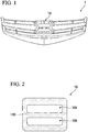
- FIG. 1 is a front view of a radiator grille 1 having an emblem 10 formed of a radar cover of the present embodiment.
- FIG. 2 is an enlarged front view of the emblem 10 of the present embodiment.
- FIG. 3A is a cross-sectional view of the emblem 10 of the present embodiment, and
- FIG. 3B is a partially enlarged cross-sectional view of an inner emblem 12 included in the emblem 10 of the present embodiment.
- the radiator grille 1 is provided on a front surface of a vehicle to close an opening that communicates with an engine room of a vehicle to ensure ventilation to the engine room and to prevent foreign matter from entering the engine room.
- the emblem 10 is provided to face a radar unit R (see FIG. 3A ) disposed in the engine room.
- the radar unit R includes, for example, a transmitter that transmits millimeter waves, a receiver that receives reflected waves, a calculator that performs a calculation process, and the like.
- the radar unit R transmits and receives electromagnetic waves through the emblem 10 and detects a surrounding condition of the vehicle on the basis of the received electromagnetic waves.
- the radar unit R calculates and outputs a distance to an obstacle, a relative speed of the obstacle, or the like, for example.
- the emblem 10 is disposed to cover the radar unit R when viewed from a front side of the vehicle.
- the emblem 10 is a component which includes a bright region 10A which represents a figure, a character, or the like indicating an emblem of a vehicle manufacturer, and a black region 10B which improves visibility of the bright region 10A.
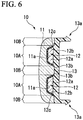
- the emblem 10 as above includes a transparent member 11 (a transparent layer), an inner emblem 12 (a fitting portion), and a base member 13 (a support member).
- the transparent member 11 is a portion formed of a substantially rectangular transparent material (including colored transparency) disposed at the outermost side of the vehicle.
- a surface of the front side of the transparent member 11 is formed in a smooth surface.
- a recessed portion 11a (a fitted portion) in which the inner emblem 12 is disposed is formed on a surface of a back side of the transparent member 11.
- a region of the surface of the back side of the transparent member 11 in which the recessed portion 11a is not provided is a fixing surface fixed to the base member 13.
- the recessed portion 11a is a portion to which the inner emblem 12 is fitted and allows the inner emblem 12 accommodated therein to be three-dimensionally visible from the front side of the vehicle.
- the recessed portion 11a is provided according to a shape of a figure, a character, or the like of an emblem or the like of a vehicle manufacturer.
- the transparent member 11 is formed of a transparent synthetic resin such as a colorless polycarbonate (PC) or a poly methyl methacrylate resin (PMMA) and has a thickness of about 1.5 mm to 10 mm.
- a hard coat treatment for preventing scratches or a clear coat treatment using a urethane-based coating material and the like is applied as needed to the surface of the front side of the transparent member 11. Further, these scratch prevention treatments are unnecessary if the material of the transparent member 11 is the transparent synthetic resin having scratch resistance.
- the inner emblem 12 includes a base portion 12a, a bright layer 12b, and a top coat layer 12c.
- the base portion 12a is a rigid member serving as a frame of the inner emblem 12 and supports the bright layer 12b and the top coat layer 12c.
- the base portion 12a is formed through injection molding or the like and is formed of a synthetic resin such as acrylonitrile-butadiene-styrene (ABS), PC, or polyethylene terephthalate (PET).
- ABS acrylonitrile-butadiene-styrene
- PC polyethylene terephthalate
- PET polyethylene terephthalate
- the base portion 12a has a convex shape to fill the recessed portion 11a of the transparent member 11 and is fitted to the recessed portion 11a of the transparent member 11.
- the bright layer 12b is formed on the surface of the front side of the base portion 12a (the surface on the transparent member 11 side, the surface closer to the transparent member 11) and is a layer having metallic brilliance disposed to cover the base portion 12a.
- the bright layer 12b is a metallic thin layer formed of indium (In) or aluminum (Al).
- the bright layer 12b is a discontinuous layer having a structure formed of islands and having a large number of fine openings 12b1 penetrating therethrough in a layer thickness direction, and the bright layer 12b is configured to allow electromagnetic waves to pass through the openings 12b1.
- an actual width of the openings 12b1 is very small, the width in the drawing is enlarged for easier viewing.
- the bright layer 12b is formed through, for example, a sputtering method.
- the bright layer 12b in the present embodiment is directly formed on the surface of the base portion 12a serving as a frame. That is, in the present embodiment, another layer such as a base coat layer is not provided between the base portion 12a and the bright layer 12b.
- the top coat layer 12c is a transparent (including colored transparency) resin layer formed of clear coating or the like, for example, and has electromagnetic wave transmissibility. As illustrated in FIG. 3B , the top coat layer 12c is formed on the surface of the bright layer 12b (the surface opposite to the base portion 12a), and parts of the top coat layer 12c are in close contact with the base portion 12a through the openings 12b1 of the bright layer 12b.
- the top coat layer 12c covers the bright layer 12b to protect the bright layer 12b from moisture or the like and holds the bright layer 12b such that the bright layer 12b does not peel off from the base portion 12a. That is, the bright layer 12b is supported by the top coat layer 12c and is firmly fixed to the base portion 12a.
- the base member 13 is a portion fixed to a back side of the transparent member 11 and is formed of a black resin material.
- the base member 13 functions as a support member which supports the inner emblem 12 from a side opposite to the transparent member 11 while being fixed to the transparent member 11.
- the base member 13 includes an engaging portion 13a protruding toward the engine room side.
- a tip portion of the engaging portion 13a is formed in a claw shape and the tip portion engages with a radiator grille main body, for example.
- the base member 13 fixed to the surface of the back side of the transparent member 11 as described above is visible from the outside of the transparent member 11 and forms the black region 10B described above.
- the base member 13 causes a region of the emblem 10 other than the bright region 10A to appear black and thus relatively improves visibility of the bright region 10A.
- Such a base member 13 is formed of a synthetic resin such as an acrylonitrile-butadiene-styrene (ABS) copolymerization synthetic resin, an acrylonitrile-ethylene-styrene (AES) copolymerization synthetic resin, acrylonitrile-styrene-acrylate (ASA), polybutylene terephthalate (PBT), colored PC, and polyethylene terephthalate (PET), or a composite resin thereof, and has a thickness of about 0.5 mm to 10 mm.
- ABS acrylonitrile-butadiene-styrene
- AES acrylonitrile-ethylene-styrene copolymerization synthetic resin
- ASA acrylonitrile-styrene-acrylate
- PBT polybutylene terephthalate
- PET polyethylene terephthalate
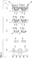
- FIG. 4 is a schematic view for describing the method of manufacturing the emblem 10 of the present embodiment.
- the transparent member 11 is formed as illustrated in FIG. 4(a) .
- the transparent member 11 is formed by injection molding. Since the transparent member 11 having the recessed portion 11a can be formed by the injection molding, it is not necessary to form the recessed portion 11a by a subsequent process. Further, a hard coat treatment for improving durability or the like may be applied as needed to a surface side (a surface facing a vehicle outer side) or an entire surface of the transparent member 11.
- the base portion 12a of the inner emblem 12 is formed as illustrated in FIG. 4(b) .
- the base portion 12a is formed by injection molding.
- the bright layer 12b is formed on the surface of the base portion 12a and the top coat layer 12c is formed as illustrated in FIG. 4(c) .
- a process of forming the bright layer 12b corresponds to a bright layer formation step of the present invention.
- a process of forming the top coat layer 12c corresponds to a top coat layer formation step of the present invention.
- the bright layer 12b is formed in a vacuum atmosphere inside a vacuum chamber, for example, by sputtering.
- the bright layer 12b formed as described above is formed as a discontinuous layer having a plurality of openings 12b1 due to poor wettability or the like of the base portion 12a.
- the top coat layer 12c is formed by coating the bright layer 12b with a clear coating material and then drying the clear coating material.
- a clear coating material As the clear coating material described above, a material having a solubility parameter close to that of the base portion 12a and having high wettability with respect to the base portion 12a and the bright layer 12b is preferable.
- the base portion 12a is formed of PC
- the inner emblem 12 is formed by the process of forming the base portion 12a illustrated in FIG. 4(b) and the process of forming the bright layer 12b and the top coat layer 12c illustrated in FIG. 4(c) . In addition, it is not necessary to wait for the process of forming the transparent member 11 illustrated in FIG. 4(a) before performing the process of forming the base portion 12a illustrated in FIG. 4(b) and the process of forming the bright layer 12b and the top coat layer 12c illustrated in FIG. 4(c) . It is possible to shorten a manufacturing time of the emblem 10 by forming the inner emblem 12 in parallel with the process of forming the transparent member 11 illustrated in FIG. 4(a) .
- the inner emblem 12 is fitted into the recessed portion 11a of the transparent member 11 as illustrated in FIG. 4(d) .
- the base member 13 is formed as illustrated in FIG. 4(e) .
- the transparent member 11, in which the inner emblem 12 is installed in the recessed portion 11a is disposed inside a mold for injection molding and insert molding in which a molten resin is injected to the back surface side of the transparent member 11 is performed to form the base member 13.
- Such a base member 13 is welded to the transparent member 11 by heat during the insert molding and is disposed to cover the inner emblem 12.
- the bright layer 12b of the inner emblem 12 is fixed to the transparent member 11 together with the base portion 12a in a state in which the bright layer 12b is in direct contact with an inner surface of the recessed portion 11a.
- the emblem 10 of the present embodiment is manufactured by the process as described above. According to the method of manufacturing the emblem 10 and the emblem 10 of the present embodiment as described above, since the top coat layer 12c is in close contact with the base portion 12a through the openings 12b1 of the bright layer 12b, the bright layer 12b is fixed to the base portion 12a. Thus, the bright layer 12b can be held without forming a base coat layer. Therefore, according to the method of manufacturing the emblem 10 and the emblem 10 of the present embodiment, the base coat layer which has been conventionally provided between the base portion 12a and the bright layer 12b is not included, and the manufacturing process can be simplified because the process of forming the base coat layer is not necessary.
- the emblem 10 of the present embodiment includes the transparent member 11 having the recessed portion 11a and the inner emblem 12 fitted to the recessed portion 11a and visible from the outside through the transparent member 11, the inner emblem 12 includes the base portion 12a, the bright layer 12b, and the top coat layer 12c, and the top coat layer 12c side of the inner emblem 12 is disposed to face an inner wall surface of the recessed portion 11 a. Therefore, it is unnecessary to perform the process of forming the base coat layer and the inner emblem 12 can be formed in a short time. Therefore, it is possible to manufacture the emblem 10 in a shorter time by forming the transparent member 11 and the inner emblem 12 in parallel.
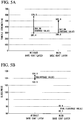
- FIG. 5A is a figure in which tensile strength of a top coat layer is compared between a case in which there is no base coat layer (the emblem of the present embodiment) and a case in which there is a base coat layer (a conventional emblem).
- the tensile strength of the emblem 10 of the present embodiment was 364.36 N on average in the range of 287.4 N to 578.0 N while the tensile strength of the conventional emblem was 347.06 N on average in the range of 300.5 N to 505.9 N.
- the adhesion of the top coat layer 12c in the emblem 10 of the present embodiment is the same as compared to the case in which the base coat layer is provided.
- smoothness of the top coat layer 12c in the emblem 10 of the present embodiment is equal to or greater than in the case in which the base coat layer is provided.
- FIG. 5B is a figure in which surface glossiness is compared between the case in which there is no base coat layer (the emblem of the present embodiment) and the case in which there is a base coat layer (a conventional emblem).
- the glossiness in the emblem 10 of the present embodiment was 104 on average in the range of 103.6 to 104.9 while the glossiness in the conventional emblem was 95.5 on average in the range of 95.3 to 95.6.
- the smoothness of the top coat layer 12c in the emblem 10 of the present embodiment is equal to or greater than in the case in which the base coat layer is provided.
- the present invention is not limited thereto.
- the emblem itself includes a base portion which serves as a frame, a bright layer which is formed on a surface of the base portion and is a discontinuous metal layer having openings penetrating therethrough in a layer thickness direction, and a transparent top coat layer formed on a surface of the bright layer, parts of the top coat layer being in close contact with the base portion through the openings of the bright layer.
- the present invention is not limited thereto.
- a pedestal portion 13b which protrudes toward the transparent member 11 more than a surrounding region may be formed in the region of the base member 13 with which the inner emblem 12 is in contact.
Landscapes
- Engineering & Computer Science (AREA)
- Radar, Positioning & Navigation (AREA)
- Remote Sensing (AREA)
- Chemical & Material Sciences (AREA)
- Physics & Mathematics (AREA)
- Mechanical Engineering (AREA)
- Computer Networks & Wireless Communication (AREA)
- General Physics & Mathematics (AREA)
- Computer Security & Cryptography (AREA)
- Chemical Kinetics & Catalysis (AREA)
- Materials Engineering (AREA)
- Metallurgy (AREA)
- Organic Chemistry (AREA)
- Electromagnetism (AREA)
- Vehicle Waterproofing, Decoration, And Sanitation Devices (AREA)
- Vehicle Interior And Exterior Ornaments, Soundproofing, And Insulation (AREA)
- Laminated Bodies (AREA)
- Injection Moulding Of Plastics Or The Like (AREA)
- Details Of Aerials (AREA)
- Radar Systems Or Details Thereof (AREA)
Claims (3)
- Eine Radarabdeckung zum Abdecken einer Radareinheit (R), von einer Vorderseite eines Fahrzeugs, die eine Situation um das Fahrzeug detektiert, umfassend:einen Einpassabschnitt (12), der konfiguriert ist aus einem Basisabschnitt (12a), der als ein Rahmen dient, undeiner Glanzschicht (12b), die direkt auf einer Oberfläche einer Vorderseite des Basisabschnitts (12a) gebildet ist und eine diskontinuierliche Metallschicht mit diese in einer Schichtdickenrichtung durchdringende Öffnungen (12b1) ist, wobei die Oberfläche der Vorderseite des Basisabschnitts (12a) aus dem gleichen Material gebildet ist wie der Basisabschnitt (12a);eine transparente Deckschicht (12c) gebildet auf einer Oberfläche einer Vorderseite der Glanzschicht (12b), wobei Teile der Deckschicht (12c) durch die Öffnungen (12b1) der Glanzschicht (12b) direkt in engem Kontakt mit der Oberfläche der Vorderseite des Basisabschnitts (12a) sind;eine transparente Schicht (11) beinhaltend einen vertieften Abschnitt (11a); und ein Stützelement (13) befestigt an der transparenten Schicht (11) und eine Seite des Einpassabschnitts (12) stützend, die der transparenten Schicht (11) gegenüberliegend ist, wobeider Einpassabschnitt (12) eine konvexe Form aufweist, um den vertieften Abschnitt zu füllen, und von außerhalb des Fahrzeugs durch die transparente Schicht (11) sichtbar ist, und der Einpassabschnitt (12) derart angeordnet ist, dass die Deckschicht (12c) einer Innenwandoberfläche des vertieften Abschnitts (11a) zugewandt ist, und das Stützelement (13) einen Sockelabschnitt (13b) beinhaltet, der in Kontakt mit dem Einpassabschnitt (12) ist.
- Die Radarabdeckung nach Anspruch 1, wobei der Sockelabschnitt (13b) derart ausgebildet ist, dass ein Bereich, in dem das Stützelement (13) in Kontakt mit dem Einpassabschnitt (12) ist, mehr hervorragt in Richtung des transparenten Elements (11) als ein Umgebungsbereich des Sockelabschnitts (13b).
- Ein Verfahren zur Herstellung einer Radarabdeckung zum Abdecken einer Radareinheit (R) von einer Vorderseite eines Fahrzeugs, wobei die Radarabdeckung eine transparente Schicht (11), einen Einpassabschnitt (12) und ein Stützelement (13) beinhaltet und eine Situation um das Fahrzeug detektiert, umfassend:einen Schritt des Bildens eines Einpassabschnitts (12) durch Ausführen eines Glanzschichtbildungsschritts des Bildens einer Glanzschicht (12b) direkt auf einer Oberfläche einer Vorderseite eines als ein Rahmen dienenden Basisabschnitts (12a), wobei die Glanzschicht (12b) eine diskontinuierliche Metallschicht mit sie in einer Schichtdickenrichtung durchdringenden Öffnungen (12b1) ist, wobei die Oberfläche der Vorderseite des Basisabschnitts (12a) aus dem gleichen Material gebildet ist wie der Basisabschnitt (12a); undeinen Deckschichtbildungsschritt des Bildens einer transparenten Deckschicht (12c) auf einer Oberfläche einer Vorderseite der Glanzschicht (12b) derart, dass Teile der Deckschicht (12c) durch die Öffnungen (12b1) der Glanzschicht (12b) direkt in engem Kontakt mit der Oberfläche der Vorderseite des Basisabschnitts (12a) sind;einen Schritt des Einpassens des Einpassabschnitts (12) in einen vertieften Abschnitt der transparenten Schicht (11) derart, dass die Deckschicht (12c) einer Innenwandoberfläche des vertieften Abschnitts (11a) zugewandt ist, wobei der Einpassabschnitt (12) eine konvexe Form aufweist, um den vertieften Abschnitt (11a) zu füllen, und von außerhalb des Fahrzeugs durch die transparente Schicht (11) sichtbar ist; undeinen Schritt des Bildens des Stützelements (13), das einen Sockelabschnitt (13b) beinhaltet, der in Kontakt mit dem Einpassabschnitt (12) ist, wobei das Stützelement (13) an der transparenten Schicht (11) befestigt wird und eine Seite des Einpassabschnitts (12) stützt, die der transparenten Schicht (11) gegenüberliegend ist.
Applications Claiming Priority (1)
| Application Number | Priority Date | Filing Date | Title |
|---|---|---|---|
| JP2016188022A JP6872336B2 (ja) | 2016-09-27 | 2016-09-27 | レーダカバー |
Publications (3)
| Publication Number | Publication Date |
|---|---|
| EP3300169A2 EP3300169A2 (de) | 2018-03-28 |
| EP3300169A3 EP3300169A3 (de) | 2018-04-04 |
| EP3300169B1 true EP3300169B1 (de) | 2019-11-06 |
Family
ID=59930241
Family Applications (1)
| Application Number | Title | Priority Date | Filing Date |
|---|---|---|---|
| EP17192372.5A Active EP3300169B1 (de) | 2016-09-27 | 2017-09-21 | Radarabdeckung und verfahren zur herstellung der radarabdeckung |
Country Status (4)
| Country | Link |
|---|---|
| US (1) | US10431884B2 (de) |
| EP (1) | EP3300169B1 (de) |
| JP (1) | JP6872336B2 (de) |
| CN (1) | CN107871924B (de) |
Families Citing this family (19)
| Publication number | Priority date | Publication date | Assignee | Title |
|---|---|---|---|---|
| JP2017106906A (ja) * | 2015-12-09 | 2017-06-15 | 現代自動車株式会社Hyundai Motor Company | 金属光沢を有する電波透過型カバー |
| WO2018077827A1 (en) * | 2016-10-24 | 2018-05-03 | Zanini Auto Grup, S.A. | Radome for vehicles |
| US11199609B2 (en) * | 2016-12-09 | 2021-12-14 | Faltec Co. Ltd. | Radar cover and method for manufacturing radar cover |
| CN111511520A (zh) * | 2017-12-28 | 2020-08-07 | Srg全球有限公司 | 用于车辆雷达系统的微孔泡沫主体部件及其制造方法 |
| JP7516707B2 (ja) | 2018-01-12 | 2024-07-17 | 日東電工株式会社 | 電波透過性金属光沢部材、これを用いた物品、及びその製造方法 |
| WO2019139122A1 (ja) * | 2018-01-12 | 2019-07-18 | 日東電工株式会社 | 電波透過性金属光沢部材、これを用いた物品、及びその製造方法 |
| EP3618179B1 (de) | 2018-08-30 | 2023-07-12 | Zanini Auto Grup, S.A. | Radarkuppel für fahrzeuge und verfahren zur herstellung der besagten radarkuppel |
| JP2020067291A (ja) * | 2018-10-22 | 2020-04-30 | 豊田合成株式会社 | 車載センサカバー |
| JP6954941B2 (ja) * | 2019-02-28 | 2021-10-27 | 株式会社ファルテック | レーダカバー |
| FR3097331B1 (fr) * | 2019-06-13 | 2022-05-06 | Plastic Omnium Cie | Radôme rétroéclairé |
| EP4028790A1 (de) * | 2019-09-11 | 2022-07-20 | HELLA Saturnus Slovenija d.o.o. | Vorrichtung zur befestigung an einer öffnung eines fahrzeuges und zum abdecken eines senders und/oder eines empfängers |
| CN112721822A (zh) * | 2019-10-14 | 2021-04-30 | 株式会社瑞延理化 | 雷达电波穿透型盖板及其制造方法 |
| CN111391230B (zh) * | 2020-06-03 | 2021-03-16 | 宁波四维尔汽车智能科技有限公司 | 一种acc汽车标牌总成生产工艺 |
| EP4105678A1 (de) | 2021-06-18 | 2022-12-21 | HELLA Saturnus Slovenija d.o.o. | Beleuchteter deckel für elektromagnetischen sender und empfänger |
| WO2023281296A1 (en) * | 2021-07-07 | 2023-01-12 | Hella Saturnus Slovenija d.o.o. | System for backlighting a radome and radar device |
| US12066563B2 (en) * | 2021-11-02 | 2024-08-20 | Stanley Electric Co., Ltd. | Vehicular lamp fitting, radar-cover removing method, and radar-cover attaching method |
| CN120091910A (zh) | 2022-10-20 | 2025-06-03 | 旭硝子欧洲玻璃公司 | 近红外传感器玻璃盖 |
| EP4369026A1 (de) * | 2022-11-10 | 2024-05-15 | Zanini Auto Grup, S.A. | Radom für fahrzeuge |
| FR3154363A1 (fr) * | 2024-03-11 | 2025-04-25 | Valeo Vision | Module réfléchissant pour une pièce de véhicule automobile |
Family Cites Families (13)
| Publication number | Priority date | Publication date | Assignee | Title |
|---|---|---|---|---|
| US5103241A (en) * | 1989-07-28 | 1992-04-07 | Hughes Aircraft Company | High Q bandpass structure for the selective transmission and reflection of high frequency radio signals |
| JP4099946B2 (ja) * | 2001-01-11 | 2008-06-11 | 株式会社ファルテック | 金属光輝色を呈する成形品の製造方法 |
| JP4022819B2 (ja) * | 2002-12-26 | 2007-12-19 | 豊田合成株式会社 | 電波透過カバー |
| JP2005212745A (ja) * | 2004-02-02 | 2005-08-11 | Toyota Motor Corp | レーダ装置ビーム経路内用成形品 |
| JP4732147B2 (ja) * | 2005-11-21 | 2011-07-27 | 豊田合成株式会社 | 樹脂製品及びその製造方法並びに金属皮膜の成膜方法 |
| JP5061539B2 (ja) * | 2005-11-21 | 2012-10-31 | 豊田合成株式会社 | 樹脂製品及びその製造方法並びに金属皮膜の成膜方法 |
| JP4863906B2 (ja) * | 2007-03-12 | 2012-01-25 | 株式会社アルバック | 光輝性膜および光輝性膜の製造方法 |
| CN101802248B (zh) * | 2007-09-18 | 2013-10-16 | 信越聚合物株式会社 | 电波透过性装饰构件 |
| JP5237713B2 (ja) * | 2008-07-25 | 2013-07-17 | 豊田合成株式会社 | 電磁波透過性光輝塗装樹脂製品及び製造方法 |
| JP5735196B2 (ja) * | 2008-09-11 | 2015-06-17 | 株式会社ファルテック | レドーム及びレドームの製造方法 |
| JP4881984B2 (ja) * | 2009-08-28 | 2012-02-22 | 株式会社ファルテック | レドームの製造方法 |
| JP5636735B2 (ja) * | 2009-09-24 | 2014-12-10 | 大日本印刷株式会社 | 透明アンテナ用エレメント及び透明アンテナ |
| DE102015217744A1 (de) * | 2015-09-16 | 2017-03-16 | Nanogate PD Systems GmbH | Radom |
-
2016
- 2016-09-27 JP JP2016188022A patent/JP6872336B2/ja active Active
-
2017
- 2017-09-21 CN CN201710857839.0A patent/CN107871924B/zh not_active Expired - Fee Related
- 2017-09-21 EP EP17192372.5A patent/EP3300169B1/de active Active
- 2017-09-25 US US15/714,367 patent/US10431884B2/en active Active
Non-Patent Citations (1)
| Title |
|---|
| None * |
Also Published As
| Publication number | Publication date |
|---|---|
| JP6872336B2 (ja) | 2021-05-19 |
| EP3300169A3 (de) | 2018-04-04 |
| JP2018056683A (ja) | 2018-04-05 |
| EP3300169A2 (de) | 2018-03-28 |
| CN107871924B (zh) | 2020-12-22 |
| US10431884B2 (en) | 2019-10-01 |
| US20180090832A1 (en) | 2018-03-29 |
| CN107871924A (zh) | 2018-04-03 |
Similar Documents
| Publication | Publication Date | Title |
|---|---|---|
| US10431884B2 (en) | Radar cover and method of manufacturing radar cover | |
| JP4881984B2 (ja) | レドームの製造方法 | |
| JP2016182866A (ja) | 車両用装着品 | |
| JP5460218B2 (ja) | レドームの製造方法 | |
| EP3933431A1 (de) | Radarabdeckung | |
| US20150076851A1 (en) | Vehicular exterior member | |
| JP2016124113A (ja) | レーダカバーの製造方法及びレーダカバー | |
| CN107949794B (zh) | 雷达罩的制造方法以及雷达罩 | |
| JP6343594B2 (ja) | レーダカバーの製造方法及びレーダカバー | |
| JP2019128255A (ja) | レーダカバー及びレーダカバーの製造方法 | |
| JP2018159584A (ja) | レーダカバーの製造方法及びレーダカバー | |
| JP7050731B2 (ja) | レーダカバー | |
| JP6868549B2 (ja) | レーダカバー | |
| JP2018159585A (ja) | レーダカバー及びレーダカバーの製造方法 | |
| JP2020147204A (ja) | 車両用カバー部材及び車両用カバー部材の製造方法 | |
| JP7482710B2 (ja) | レーダカバー及びレーダカバーの製造方法 | |
| JP7034123B2 (ja) | レーダカバー | |
| JP7561570B2 (ja) | レーダカバー及びレーダカバーの製造方法 | |
| JP6954962B2 (ja) | レーダカバー及びレーダカバーの製造方法 | |
| JP6883493B2 (ja) | レーダカバー及びレーダカバーの製造方法 | |
| JP2021025776A (ja) | レーダカバー | |
| JP2020085804A (ja) | レーダカバー |
Legal Events
| Date | Code | Title | Description |
|---|---|---|---|
| PUAI | Public reference made under article 153(3) epc to a published international application that has entered the european phase |
Free format text: ORIGINAL CODE: 0009012 |
|
| STAA | Information on the status of an ep patent application or granted ep patent |
Free format text: STATUS: REQUEST FOR EXAMINATION WAS MADE |
|
| PUAL | Search report despatched |
Free format text: ORIGINAL CODE: 0009013 |
|
| STAA | Information on the status of an ep patent application or granted ep patent |
Free format text: STATUS: EXAMINATION IS IN PROGRESS |
|
| 17P | Request for examination filed |
Effective date: 20170921 |
|
| AK | Designated contracting states |
Kind code of ref document: A2 Designated state(s): AL AT BE BG CH CY CZ DE DK EE ES FI FR GB GR HR HU IE IS IT LI LT LU LV MC MK MT NL NO PL PT RO RS SE SI SK SM TR |
|
| AX | Request for extension of the european patent |
Extension state: BA ME |
|
| AK | Designated contracting states |
Kind code of ref document: A3 Designated state(s): AL AT BE BG CH CY CZ DE DK EE ES FI FR GB GR HR HU IE IS IT LI LT LU LV MC MK MT NL NO PL PT RO RS SE SI SK SM TR |
|
| AX | Request for extension of the european patent |
Extension state: BA ME |
|
| RIC1 | Information provided on ipc code assigned before grant |
Ipc: H01Q 1/42 20060101ALI20180223BHEP Ipc: B44C 1/00 20060101ALI20180223BHEP Ipc: B60R 13/00 20060101ALI20180223BHEP Ipc: H01Q 1/32 20060101AFI20180223BHEP Ipc: G01S 13/93 20060101ALI20180223BHEP |
|
| 17Q | First examination report despatched |
Effective date: 20180315 |
|
| RIC1 | Information provided on ipc code assigned before grant |
Ipc: G01S 13/93 20060101ALI20190320BHEP Ipc: H01Q 1/42 20060101ALI20190320BHEP Ipc: B60R 13/00 20060101ALI20190320BHEP Ipc: G01S 7/02 20060101ALI20190320BHEP Ipc: H01Q 1/32 20060101AFI20190320BHEP Ipc: B44C 1/00 20060101ALI20190320BHEP |
|
| GRAP | Despatch of communication of intention to grant a patent |
Free format text: ORIGINAL CODE: EPIDOSNIGR1 |
|
| STAA | Information on the status of an ep patent application or granted ep patent |
Free format text: STATUS: GRANT OF PATENT IS INTENDED |
|
| INTG | Intention to grant announced |
Effective date: 20190503 |
|
| RIN1 | Information on inventor provided before grant (corrected) |
Inventor name: OOTA, KOUSHIROU Inventor name: TAKAHASHI, MASAKAZU |
|
| GRAS | Grant fee paid |
Free format text: ORIGINAL CODE: EPIDOSNIGR3 |
|
| GRAJ | Information related to disapproval of communication of intention to grant by the applicant or resumption of examination proceedings by the epo deleted |
Free format text: ORIGINAL CODE: EPIDOSDIGR1 |
|
| GRAL | Information related to payment of fee for publishing/printing deleted |
Free format text: ORIGINAL CODE: EPIDOSDIGR3 |
|
| STAA | Information on the status of an ep patent application or granted ep patent |
Free format text: STATUS: EXAMINATION IS IN PROGRESS |
|
| GRAR | Information related to intention to grant a patent recorded |
Free format text: ORIGINAL CODE: EPIDOSNIGR71 |
|
| STAA | Information on the status of an ep patent application or granted ep patent |
Free format text: STATUS: GRANT OF PATENT IS INTENDED |
|
| GRAA | (expected) grant |
Free format text: ORIGINAL CODE: 0009210 |
|
| STAA | Information on the status of an ep patent application or granted ep patent |
Free format text: STATUS: THE PATENT HAS BEEN GRANTED |
|
| INTC | Intention to grant announced (deleted) | ||
| AK | Designated contracting states |
Kind code of ref document: B1 Designated state(s): AL AT BE BG CH CY CZ DE DK EE ES FI FR GB GR HR HU IE IS IT LI LT LU LV MC MK MT NL NO PL PT RO RS SE SI SK SM TR |
|
| INTG | Intention to grant announced |
Effective date: 20191001 |
|
| REG | Reference to a national code |
Ref country code: GB Ref legal event code: FG4D |
|
| REG | Reference to a national code |
Ref country code: CH Ref legal event code: EP Ref country code: AT Ref legal event code: REF Ref document number: 1200060 Country of ref document: AT Kind code of ref document: T Effective date: 20191115 |
|
| REG | Reference to a national code |
Ref country code: IE Ref legal event code: FG4D |
|
| REG | Reference to a national code |
Ref country code: DE Ref legal event code: R096 Ref document number: 602017008406 Country of ref document: DE |
|
| REG | Reference to a national code |
Ref country code: NL Ref legal event code: MP Effective date: 20191106 |
|
| REG | Reference to a national code |
Ref country code: LT Ref legal event code: MG4D |
|
| PG25 | Lapsed in a contracting state [announced via postgrant information from national office to epo] |
Ref country code: LT Free format text: LAPSE BECAUSE OF FAILURE TO SUBMIT A TRANSLATION OF THE DESCRIPTION OR TO PAY THE FEE WITHIN THE PRESCRIBED TIME-LIMIT Effective date: 20191106 Ref country code: PL Free format text: LAPSE BECAUSE OF FAILURE TO SUBMIT A TRANSLATION OF THE DESCRIPTION OR TO PAY THE FEE WITHIN THE PRESCRIBED TIME-LIMIT Effective date: 20191106 Ref country code: NL Free format text: LAPSE BECAUSE OF FAILURE TO SUBMIT A TRANSLATION OF THE DESCRIPTION OR TO PAY THE FEE WITHIN THE PRESCRIBED TIME-LIMIT Effective date: 20191106 Ref country code: SE Free format text: LAPSE BECAUSE OF FAILURE TO SUBMIT A TRANSLATION OF THE DESCRIPTION OR TO PAY THE FEE WITHIN THE PRESCRIBED TIME-LIMIT Effective date: 20191106 Ref country code: NO Free format text: LAPSE BECAUSE OF FAILURE TO SUBMIT A TRANSLATION OF THE DESCRIPTION OR TO PAY THE FEE WITHIN THE PRESCRIBED TIME-LIMIT Effective date: 20200206 Ref country code: LV Free format text: LAPSE BECAUSE OF FAILURE TO SUBMIT A TRANSLATION OF THE DESCRIPTION OR TO PAY THE FEE WITHIN THE PRESCRIBED TIME-LIMIT Effective date: 20191106 Ref country code: FI Free format text: LAPSE BECAUSE OF FAILURE TO SUBMIT A TRANSLATION OF THE DESCRIPTION OR TO PAY THE FEE WITHIN THE PRESCRIBED TIME-LIMIT Effective date: 20191106 Ref country code: BG Free format text: LAPSE BECAUSE OF FAILURE TO SUBMIT A TRANSLATION OF THE DESCRIPTION OR TO PAY THE FEE WITHIN THE PRESCRIBED TIME-LIMIT Effective date: 20200206 Ref country code: PT Free format text: LAPSE BECAUSE OF FAILURE TO SUBMIT A TRANSLATION OF THE DESCRIPTION OR TO PAY THE FEE WITHIN THE PRESCRIBED TIME-LIMIT Effective date: 20200306 Ref country code: GR Free format text: LAPSE BECAUSE OF FAILURE TO SUBMIT A TRANSLATION OF THE DESCRIPTION OR TO PAY THE FEE WITHIN THE PRESCRIBED TIME-LIMIT Effective date: 20200207 |
|
| PG25 | Lapsed in a contracting state [announced via postgrant information from national office to epo] |
Ref country code: IS Free format text: LAPSE BECAUSE OF FAILURE TO SUBMIT A TRANSLATION OF THE DESCRIPTION OR TO PAY THE FEE WITHIN THE PRESCRIBED TIME-LIMIT Effective date: 20200306 Ref country code: HR Free format text: LAPSE BECAUSE OF FAILURE TO SUBMIT A TRANSLATION OF THE DESCRIPTION OR TO PAY THE FEE WITHIN THE PRESCRIBED TIME-LIMIT Effective date: 20191106 Ref country code: RS Free format text: LAPSE BECAUSE OF FAILURE TO SUBMIT A TRANSLATION OF THE DESCRIPTION OR TO PAY THE FEE WITHIN THE PRESCRIBED TIME-LIMIT Effective date: 20191106 |
|
| PG25 | Lapsed in a contracting state [announced via postgrant information from national office to epo] |
Ref country code: AL Free format text: LAPSE BECAUSE OF FAILURE TO SUBMIT A TRANSLATION OF THE DESCRIPTION OR TO PAY THE FEE WITHIN THE PRESCRIBED TIME-LIMIT Effective date: 20191106 |
|
| PG25 | Lapsed in a contracting state [announced via postgrant information from national office to epo] |
Ref country code: RO Free format text: LAPSE BECAUSE OF FAILURE TO SUBMIT A TRANSLATION OF THE DESCRIPTION OR TO PAY THE FEE WITHIN THE PRESCRIBED TIME-LIMIT Effective date: 20191106 Ref country code: CZ Free format text: LAPSE BECAUSE OF FAILURE TO SUBMIT A TRANSLATION OF THE DESCRIPTION OR TO PAY THE FEE WITHIN THE PRESCRIBED TIME-LIMIT Effective date: 20191106 Ref country code: ES Free format text: LAPSE BECAUSE OF FAILURE TO SUBMIT A TRANSLATION OF THE DESCRIPTION OR TO PAY THE FEE WITHIN THE PRESCRIBED TIME-LIMIT Effective date: 20191106 Ref country code: EE Free format text: LAPSE BECAUSE OF FAILURE TO SUBMIT A TRANSLATION OF THE DESCRIPTION OR TO PAY THE FEE WITHIN THE PRESCRIBED TIME-LIMIT Effective date: 20191106 Ref country code: DK Free format text: LAPSE BECAUSE OF FAILURE TO SUBMIT A TRANSLATION OF THE DESCRIPTION OR TO PAY THE FEE WITHIN THE PRESCRIBED TIME-LIMIT Effective date: 20191106 |
|
| REG | Reference to a national code |
Ref country code: DE Ref legal event code: R097 Ref document number: 602017008406 Country of ref document: DE |
|
| REG | Reference to a national code |
Ref country code: AT Ref legal event code: MK05 Ref document number: 1200060 Country of ref document: AT Kind code of ref document: T Effective date: 20191106 |
|
| PG25 | Lapsed in a contracting state [announced via postgrant information from national office to epo] |
Ref country code: SM Free format text: LAPSE BECAUSE OF FAILURE TO SUBMIT A TRANSLATION OF THE DESCRIPTION OR TO PAY THE FEE WITHIN THE PRESCRIBED TIME-LIMIT Effective date: 20191106 Ref country code: SK Free format text: LAPSE BECAUSE OF FAILURE TO SUBMIT A TRANSLATION OF THE DESCRIPTION OR TO PAY THE FEE WITHIN THE PRESCRIBED TIME-LIMIT Effective date: 20191106 |
|
| PLBE | No opposition filed within time limit |
Free format text: ORIGINAL CODE: 0009261 |
|
| STAA | Information on the status of an ep patent application or granted ep patent |
Free format text: STATUS: NO OPPOSITION FILED WITHIN TIME LIMIT |
|
| 26N | No opposition filed |
Effective date: 20200807 |
|
| PG25 | Lapsed in a contracting state [announced via postgrant information from national office to epo] |
Ref country code: AT Free format text: LAPSE BECAUSE OF FAILURE TO SUBMIT A TRANSLATION OF THE DESCRIPTION OR TO PAY THE FEE WITHIN THE PRESCRIBED TIME-LIMIT Effective date: 20191106 Ref country code: SI Free format text: LAPSE BECAUSE OF FAILURE TO SUBMIT A TRANSLATION OF THE DESCRIPTION OR TO PAY THE FEE WITHIN THE PRESCRIBED TIME-LIMIT Effective date: 20191106 |
|
| PG25 | Lapsed in a contracting state [announced via postgrant information from national office to epo] |
Ref country code: IT Free format text: LAPSE BECAUSE OF FAILURE TO SUBMIT A TRANSLATION OF THE DESCRIPTION OR TO PAY THE FEE WITHIN THE PRESCRIBED TIME-LIMIT Effective date: 20191106 |
|
| REG | Reference to a national code |
Ref country code: CH Ref legal event code: PL |
|
| REG | Reference to a national code |
Ref country code: BE Ref legal event code: MM Effective date: 20200930 |
|
| PG25 | Lapsed in a contracting state [announced via postgrant information from national office to epo] |
Ref country code: LU Free format text: LAPSE BECAUSE OF NON-PAYMENT OF DUE FEES Effective date: 20200921 |
|
| PG25 | Lapsed in a contracting state [announced via postgrant information from national office to epo] |
Ref country code: CH Free format text: LAPSE BECAUSE OF NON-PAYMENT OF DUE FEES Effective date: 20200930 Ref country code: BE Free format text: LAPSE BECAUSE OF NON-PAYMENT OF DUE FEES Effective date: 20200930 Ref country code: IE Free format text: LAPSE BECAUSE OF NON-PAYMENT OF DUE FEES Effective date: 20200921 Ref country code: LI Free format text: LAPSE BECAUSE OF NON-PAYMENT OF DUE FEES Effective date: 20200930 |
|
| PG25 | Lapsed in a contracting state [announced via postgrant information from national office to epo] |
Ref country code: TR Free format text: LAPSE BECAUSE OF FAILURE TO SUBMIT A TRANSLATION OF THE DESCRIPTION OR TO PAY THE FEE WITHIN THE PRESCRIBED TIME-LIMIT Effective date: 20191106 Ref country code: MT Free format text: LAPSE BECAUSE OF FAILURE TO SUBMIT A TRANSLATION OF THE DESCRIPTION OR TO PAY THE FEE WITHIN THE PRESCRIBED TIME-LIMIT Effective date: 20191106 Ref country code: CY Free format text: LAPSE BECAUSE OF FAILURE TO SUBMIT A TRANSLATION OF THE DESCRIPTION OR TO PAY THE FEE WITHIN THE PRESCRIBED TIME-LIMIT Effective date: 20191106 |
|
| PG25 | Lapsed in a contracting state [announced via postgrant information from national office to epo] |
Ref country code: MK Free format text: LAPSE BECAUSE OF FAILURE TO SUBMIT A TRANSLATION OF THE DESCRIPTION OR TO PAY THE FEE WITHIN THE PRESCRIBED TIME-LIMIT Effective date: 20191106 Ref country code: MC Free format text: LAPSE BECAUSE OF FAILURE TO SUBMIT A TRANSLATION OF THE DESCRIPTION OR TO PAY THE FEE WITHIN THE PRESCRIBED TIME-LIMIT Effective date: 20191106 |
|
| PGFP | Annual fee paid to national office [announced via postgrant information from national office to epo] |
Ref country code: GB Payment date: 20220728 Year of fee payment: 6 Ref country code: DE Payment date: 20220803 Year of fee payment: 6 |
|
| PGFP | Annual fee paid to national office [announced via postgrant information from national office to epo] |
Ref country code: FR Payment date: 20220808 Year of fee payment: 6 |
|
| REG | Reference to a national code |
Ref country code: DE Ref legal event code: R119 Ref document number: 602017008406 Country of ref document: DE |
|
| GBPC | Gb: european patent ceased through non-payment of renewal fee |
Effective date: 20230921 |
|
| PG25 | Lapsed in a contracting state [announced via postgrant information from national office to epo] |
Ref country code: GB Free format text: LAPSE BECAUSE OF NON-PAYMENT OF DUE FEES Effective date: 20230921 |
|
| PG25 | Lapsed in a contracting state [announced via postgrant information from national office to epo] |
Ref country code: GB Free format text: LAPSE BECAUSE OF NON-PAYMENT OF DUE FEES Effective date: 20230921 Ref country code: FR Free format text: LAPSE BECAUSE OF NON-PAYMENT OF DUE FEES Effective date: 20230930 Ref country code: DE Free format text: LAPSE BECAUSE OF NON-PAYMENT OF DUE FEES Effective date: 20240403 |