EP3300182A1 - Abschirmungsgehäuse und verbinder damit - Google Patents
Abschirmungsgehäuse und verbinder damit Download PDFInfo
- Publication number
- EP3300182A1 EP3300182A1 EP16796513.6A EP16796513A EP3300182A1 EP 3300182 A1 EP3300182 A1 EP 3300182A1 EP 16796513 A EP16796513 A EP 16796513A EP 3300182 A1 EP3300182 A1 EP 3300182A1
- Authority
- EP
- European Patent Office
- Prior art keywords
- plate
- shell
- base
- holding
- terminal
- Prior art date
- Legal status (The legal status is an assumption and is not a legal conclusion. Google has not performed a legal analysis and makes no representation as to the accuracy of the status listed.)
- Withdrawn
Links
- 239000002184 metal Substances 0.000 claims description 26
- 239000004020 conductor Substances 0.000 description 32
- 230000005540 biological transmission Effects 0.000 description 30
- 239000012212 insulator Substances 0.000 description 12
- 238000005452 bending Methods 0.000 description 10
- 230000003247 decreasing effect Effects 0.000 description 10
- 238000009413 insulation Methods 0.000 description 4
- 238000000034 method Methods 0.000 description 4
- 239000011347 resin Substances 0.000 description 4
- 229920005989 resin Polymers 0.000 description 4
- 230000007423 decrease Effects 0.000 description 3
- 239000000758 substrate Substances 0.000 description 3
- 238000005266 casting Methods 0.000 description 2
- 239000011888 foil Substances 0.000 description 2
- 238000003825 pressing Methods 0.000 description 2
- 239000000463 material Substances 0.000 description 1
- 230000013011 mating Effects 0.000 description 1
- 238000000926 separation method Methods 0.000 description 1
Images



Classifications
-
- H—ELECTRICITY
- H01—ELECTRIC ELEMENTS
- H01R—ELECTRICALLY-CONDUCTIVE CONNECTIONS; STRUCTURAL ASSOCIATIONS OF A PLURALITY OF MUTUALLY-INSULATED ELECTRICAL CONNECTING ELEMENTS; COUPLING DEVICES; CURRENT COLLECTORS
- H01R13/00—Details of coupling devices of the kinds covered by groups H01R12/70 or H01R24/00 - H01R33/00
- H01R13/648—Protective earth or shield arrangements on coupling devices, e.g. anti-static shielding
- H01R13/658—High frequency shielding arrangements, e.g. against EMI [Electro-Magnetic Interference] or EMP [Electro-Magnetic Pulse]
- H01R13/6581—Shield structure
- H01R13/6585—Shielding material individually surrounding or interposed between mutually spaced contacts
- H01R13/6589—Shielding material individually surrounding or interposed between mutually spaced contacts with wires separated by conductive housing parts
-
- H—ELECTRICITY
- H01—ELECTRIC ELEMENTS
- H01R—ELECTRICALLY-CONDUCTIVE CONNECTIONS; STRUCTURAL ASSOCIATIONS OF A PLURALITY OF MUTUALLY-INSULATED ELECTRICAL CONNECTING ELEMENTS; COUPLING DEVICES; CURRENT COLLECTORS
- H01R13/00—Details of coupling devices of the kinds covered by groups H01R12/70 or H01R24/00 - H01R33/00
- H01R13/46—Bases; Cases
- H01R13/502—Bases; Cases composed of different pieces
-
- H—ELECTRICITY
- H01—ELECTRIC ELEMENTS
- H01R—ELECTRICALLY-CONDUCTIVE CONNECTIONS; STRUCTURAL ASSOCIATIONS OF A PLURALITY OF MUTUALLY-INSULATED ELECTRICAL CONNECTING ELEMENTS; COUPLING DEVICES; CURRENT COLLECTORS
- H01R13/00—Details of coupling devices of the kinds covered by groups H01R12/70 or H01R24/00 - H01R33/00
- H01R13/648—Protective earth or shield arrangements on coupling devices, e.g. anti-static shielding
-
- H—ELECTRICITY
- H01—ELECTRIC ELEMENTS
- H01R—ELECTRICALLY-CONDUCTIVE CONNECTIONS; STRUCTURAL ASSOCIATIONS OF A PLURALITY OF MUTUALLY-INSULATED ELECTRICAL CONNECTING ELEMENTS; COUPLING DEVICES; CURRENT COLLECTORS
- H01R13/00—Details of coupling devices of the kinds covered by groups H01R12/70 or H01R24/00 - H01R33/00
- H01R13/648—Protective earth or shield arrangements on coupling devices, e.g. anti-static shielding
- H01R13/658—High frequency shielding arrangements, e.g. against EMI [Electro-Magnetic Interference] or EMP [Electro-Magnetic Pulse]
- H01R13/6581—Shield structure
- H01R13/6585—Shielding material individually surrounding or interposed between mutually spaced contacts
- H01R13/6586—Shielding material individually surrounding or interposed between mutually spaced contacts for separating multiple connector modules
-
- H—ELECTRICITY
- H01—ELECTRIC ELEMENTS
- H01R—ELECTRICALLY-CONDUCTIVE CONNECTIONS; STRUCTURAL ASSOCIATIONS OF A PLURALITY OF MUTUALLY-INSULATED ELECTRICAL CONNECTING ELEMENTS; COUPLING DEVICES; CURRENT COLLECTORS
- H01R13/00—Details of coupling devices of the kinds covered by groups H01R12/70 or H01R24/00 - H01R33/00
- H01R13/648—Protective earth or shield arrangements on coupling devices, e.g. anti-static shielding
- H01R13/658—High frequency shielding arrangements, e.g. against EMI [Electro-Magnetic Interference] or EMP [Electro-Magnetic Pulse]
- H01R13/6591—Specific features or arrangements of connection of shield to conductive members
- H01R13/6592—Specific features or arrangements of connection of shield to conductive members the conductive member being a shielded cable
- H01R13/6593—Specific features or arrangements of connection of shield to conductive members the conductive member being a shielded cable the shield being composed of different pieces
-
- H—ELECTRICITY
- H01—ELECTRIC ELEMENTS
- H01R—ELECTRICALLY-CONDUCTIVE CONNECTIONS; STRUCTURAL ASSOCIATIONS OF A PLURALITY OF MUTUALLY-INSULATED ELECTRICAL CONNECTING ELEMENTS; COUPLING DEVICES; CURRENT COLLECTORS
- H01R13/00—Details of coupling devices of the kinds covered by groups H01R12/70 or H01R24/00 - H01R33/00
- H01R13/648—Protective earth or shield arrangements on coupling devices, e.g. anti-static shielding
- H01R13/658—High frequency shielding arrangements, e.g. against EMI [Electro-Magnetic Interference] or EMP [Electro-Magnetic Pulse]
- H01R13/6591—Specific features or arrangements of connection of shield to conductive members
- H01R13/65912—Specific features or arrangements of connection of shield to conductive members for shielded multiconductor cable
- H01R13/65914—Connection of shield to additional grounding conductors
-
- H—ELECTRICITY
- H01—ELECTRIC ELEMENTS
- H01R—ELECTRICALLY-CONDUCTIVE CONNECTIONS; STRUCTURAL ASSOCIATIONS OF A PLURALITY OF MUTUALLY-INSULATED ELECTRICAL CONNECTING ELEMENTS; COUPLING DEVICES; CURRENT COLLECTORS
- H01R2105/00—Three poles
Definitions
- the present invention relates to a shield case and a connector having the same.
- Patent Literature 1 identified below discloses a conventional first connector.
- the first connector includes a housing, a shell, terminals, and a plurality of cables.
- the shell is held by the housing and holds the cables at spaced intervals along a first direction.
- the first direction is the longitudinal direction of the shell.
- the shell includes a base and a plurality of holding portions.
- the base is a rectangular plate extending in the first direction.
- the holding portions each include a trunk and a holding portion body.
- the trunks are plates extending in a second direction from an end in the second direction of the base and being arranged at spaced intervals along the first direction.
- the second direction is the short direction of the shell.
- the holding portion bodies are plates being provided at distal ends of the trunks and extending in the first direction.
- the holding portion bodies are curved such as to be wound around the peripheries of the cables.
- the terminals are held by the housing and connected to the core wires of the cables.
- the shell of the first connector is formed by press-forming a single metal plate.
- adjacent ones of the holding portions, in planar development state, need be disposed at predetermined intervals along the first direction. This necessity results in increased dimension of the shell in the first direction.
- Patent Literature 2 identified below discloses a conventional second connector, which may solve the above problem of the first connector.
- the second connector has a shell including a base and a plurality of holding portions.
- the base is a rectangular plate extending in a first direction.
- the first direction is the longitudinal direction of the shell of the second connector.
- the holding portions each include a trunk, a first holding piece, and a second holding piece.
- the trunks are plates extending in a second direction from an end in the second direction of the base and are arranged at spaced intervals along the first direction of the base.
- the second direction is the short direction of the shell of the second connector.
- the trunks each include a front portion and a rear portion in the second direction.
- the first holding pieces extend from the rear portions of the trunks to the one side of the first direction.
- the second holding pieces extend from the front portions of the trunk to the other side in the first direction.
- the first holding piece of one of the holding portions and the second holding portion of the other holding portion partially coincide each other in the second direction. Accordingly the space between the adjacent holding portions is decreased, decreasing the dimension of the shell in the first direction.
- the invention is conceived in view of the above problems, and the invention provides a shield case with a reduced dimension in a first direction in three-dimensional state and with a larger space in the first direction between adjacent holding plates in planar development state.
- the invention also provides a connector having such shield case.
- a shield case of an aspect of the invention includes a first shell constituted by a metal plate.
- the first shell includes a first base of a plate-like shape, a second base of a plate-like shape, a center plate, a first inner plate, a second inner plate, a first holding plate, and a second holding plate.
- the first base and the second base are arranged in spaced side-by-side relation along a first direction.
- the first base comprises a first end at a side of the second base and a second end at one side of a second direction.
- the second direction crosses the first direction.
- the second base includes a first end at a side of the first base and a second end at one side of the second direction.
- the center plate is arranged on one side of a third direction relative to the first and second bases, and the center plate includes a first end on the one side of the first direction and a second end on the other side of the first direction.
- the third direction crosses the first and second directions.
- the first inner plate extends to the one side of the third direction, from the first end of the first base to the first end of the center plate.
- the second inner plate extends to the one side of the third direction, from the first end of the second base to the second end of the center plate.
- the first holding plate is integral and contiguous with the second end of the first base.
- the second holding plate is integral and contiguous with the second end of the second base.
- the shield case of this aspect has the following technical features.
- the first shell of the shield case in three-dimensional state a decreased dimension in the first direction for the following reasons.
- the first shell of the shield case in the three-dimensional state is configured such that: the center plate is arranged on the one side of the third direction relative to the first base and the second base; the first inner plate extends to the one side of the third direction, from the first end of the first base to the first end of the center plate; and the second inner plate extends to the one side of the third direction, from the first end of the second base to the second end of the center plate.
- the space in the first direction between the first base and the second base is narrow, thereby decreasing the dimension in the first direction of the first shell in the three-dimensional state.
- the first shell of the shield case in planar development state has an increased space in the first direction between the first holding plate and the second holding plate.
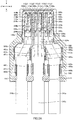
- the first shell in planar development state is configured such that the center plate, the first inner plate, the second inner plate, the first base, and the second base are aligned along the first direction.
- Such alignment results in that the space in the first direction between the first base and the second base increases by the sum of the dimensions in the first direction of the center plate, the first inner plate and the second inner plate.
- the space in the first direction substantially increases between the first holding plate, which is integral and contiguous with the first base, and the second holding plate, which is integral and contiguous with the second base. Therefore, it is easy to form the first holding plate and the second holding plate when pressing a single metal plate to form the first shell.
- the first shell may further include a first outer plate and a second outer plate.
- the first outer plate may be formed at the first base and located on the one side of the first direction relative to the first inner plate with a space therebetween.
- the second outer plate may be formed at the second base and located on the other side of the first direction relative to the second inner plate with a space therebetween.
- the shield case of this aspect is provided with a first housing space and a second housing space.
- the first housing space is defined by the first base, the first inner plate, and the first outer plate.
- the second housing space is defined by the second base, the second inner plate, and the second outer plate.
- the shield case of any of the above aspects may further include a block portion having electrical conductivity.
- the block portion may be arranged in abutment with or in spaced relation to the center plate of the first shell.
- the block portion may include a first facing portion and a second facing portion.
- the first facing portion may be arranged in facing relation to and in spaced relation in the third direction to the first base.
- the second facing portion may be arranged in facing relation to and in spaced relation in the third direction to the second base.
- the shield case of this aspect is provided with a first housing space and a second housing space.
- the first housing space is defined by the first base, the first inner plate, and the first facing portion.
- the second housing space is defined by the second base, the second inner plate, and the first facing portion.
- the first shell may further include a first engaging portion.
- the first engaging portion may be provided at at least one of the first inner plate, the second inner plate, and the center plate.
- the block portion may further include a second engaging portion.
- One of the first engaging portion and the second engaging portion may include an engaging protrusion, and the other may include an engaging hole to engage with the engaging protrusion. In the shield case of this aspect, it is easy to engage the block portion with the first shell.
- the shield case of any of the above aspects may further include a second shell having electrical conductivity.
- the second shell may include a shell body.
- the first shell of any of the above aspects may further include a fifth engaging portion provided at at least one of the first base and the second base.
- the second shell may further include a sixth engaging portion provided at the shell body.
- One of the fifth engaging portion and the sixth engaging portion comprises an engaging protrusion, and the other comprises an engaging hole to engage with the engaging protrusion. In the shield case of this aspect, it is easy to engage the second shell with the first shell.
- the shield case of any of the above aspects may further include a third shell having electrical conductivity.
- the third shell may include a first plate and a third holding plate.
- the first plate of the third shell may be arranged between the first base and the second base or between the first inner plate and the second inner plate.
- the first plate may include an end on one side of the second direction.
- the third holding plate of the third shell may be provided at the end of the first plate of the third shell and arranged between the first holding plate and the second holding plate.
- the existence of the third shell does not result in increase in dimension in the first direction of the shield case in three-dimensional state for the following reason.
- the first plate of the third shell is arranged between the first base and the second base or between the first inner plate and the second inner plate, and the third holding plate of the third shell is arranged between the first holding plate and the second holding plate.
- the third shell may further include a shell body between the first inner plate and the second inner plate.
- the shell body of the third shell may include the first plate of the third shell, a second plate and a third plate.
- the first plate of the shell body may interjoin the second plate and the third plate.
- the second plate of the shell body of the third shell may be in abutment with the first inner plate.
- the third plate of the shell body may be in abutment with the second inner plate.
- the shield case of this aspect has improved strength. This is because the second plate of the shell body of the third shell abuts the first inner plate, and the third plate of the shell body of the third shell abuts the second inner plate.
- the shell body of the third shell may further include a fourth plate.
- the fourth plate of the third shell may interjoin the second plate and the third plate.
- the fourth plate of the third shell may be in abutment with the center plate of the first shell.
- the shield case of this aspect has further improved strength. This is because the fourth plate of the shell body of the third shell abuts the center plate of the first shell.
- the second shell of any of the above aspects may further include a seventh engaging portion provided at the shell body of the second shell.
- the third shell of any of the above aspects may include an eighth engaging portion.
- One of the seventh engaging portion and the eighth engaging portion may include an engaging protrusion, and the other may include an engaging hole to engage with the engaging protrusion. In the shield case of this aspect, it is easy to engage the third shell with the second shell.
- a connector of a first aspect of the invention may include a first terminal, a second terminal, the shield case of any of the above aspects, a first cable, and a second cable.
- the first cable may be electrically connected to the first terminal and held by the first holding plate of the first shell.
- the second cable may be electrically connected to the second terminal and held by the second holding plate of the first shell.
- the connector of the first aspect may further include a first body.
- the first body may hold the first terminal and the second terminal.
- the connector of this aspect has a decreased number of components. This is because the first terminal and the second terminal are held by a single first body.
- the connector of the first aspect may further include a first body and a second body. In this case, the first body may hold the first terminal and the second body may hold the second terminal.
- the second shell of any of the above aspects may have electrical conductivity and house at least the first body.
- the second shell of any of the above aspects may have electrical conductivity and house the first body and the second body.
- the second shell may be omitted.
- the first body may include a first holding portion, a second holding portion, and a joint portion.
- the first holding portion may be arranged on the first base of the first shell to hold the first terminal.
- the second holding portion may be arranged on the second base of the first shell to hold the second terminal.
- the joint portion may interjoin the first holding portion and the second holding portion. If the first body holds the first terminal and the second body holds the second terminal, the first body may be arranged on the first base of the first shell, and the second body may be arranged on the second base of the first shell.
- the second shell of any of the above aspects may include the block portion of any of the above aspects. Also, the shell body of the second shell of any of the above aspects may be arranged on the other side or the one side of the second direction relative to the first shell.
- the shell body of the second shell may house the first body, may house the first body and the second body, or may house the first body and the third body.
- the shield case of any of the above aspects may further include a first cover and a second cover.
- the first cover may be provided at the block portion to cover the first cable partially.
- the second cover may be provided at the block portion to cover the second cable partially.
- the first holding plate may hold the first cover and the first cable.
- the second holding plate may hold the second cover and the second cable.
- the shield case of any of the above aspects may further include a third cover.
- the third cover may be provided at the block portion of any of the above aspects to cover the third cable partially.
- the third cover may not be provided at the block portion but at the fourth plate of the third shell of any of the above aspects.
- the third holding plate of the third shell of any of the above aspects may hold the third cover and the third cable.
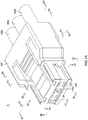
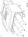
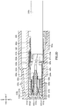
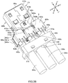
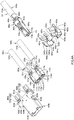
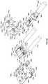
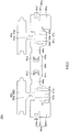
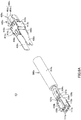
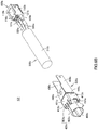
- the first unit C1 includes a body 100a (first body), at least one first terminal 200a, at least one second terminal 200b, a first cable 300a, a second cable 300b, a first shell 400a, and a second shell 400b.
- the second unit C2 includes a body 100b (third body), at least one third terminal 200c, a third cable 300c, and a third shell 400c.
- the first shell 400a, the second shell 400b, and the third shell 400c constitute a shield case S of the connector C.
- a plurality of the first terminals 200a, a plurality of the second terminals 200b, and a plurality of the third terminals 200c may be provided.
- the first and second terminals 200a and 200b are each constituted by a metal plate.
- the first and second terminals 200a and 200b are held by the body 100a.
- Each first terminal 200a includes a contact portion 210a, an intermediate portion 220a, and a tail 230a.
- the intermediate portion 220a may only interjoin the contact portion 210a and the tail portion 230a and be adapted to be held by the body 100a.
- the intermediate portion 220a includes a first plate 221a, a second plate 222a, and at least one joint plate 223a.
- the first plate 221a and the second plate 222a extend in the Y-Y' direction and face each other in the Z-Z' direction.
- the joint plate 223a interjoins the first plate 221a and the second plate 222a.
- Each contact portion 210a may only be contactable with a corresponding terminal of a mating connector.
- the contact portion 210a may include a pair of arms 211a facing each other in Z-Z' direction.
- One of the arms 211a extends from the first plate 221a in the Y direction and the other arm 211a extends from the second plate 222a in the Y direction.
- Distal end portions of the arms 211a are bent such as to approach each other.
- the tail 230a may only extend from the intermediate portion 220a in the Y' direction.
- the tail 230a may extend from the first plate 221a of the intermediate portion 220a in the Y' direction.
- the second terminal 220b will not be described because it has a similar configuration to that of the first terminal 200a.
- Each second terminal 200b includes a contact portion 210b, an intermediate portion 220b, and a tail 230b.
- the body 100a is constituted by insulation resin.
- the body 100a includes a main body 110a.
- the main body 110a is a rectangular block.
- the main body 110a includes a first holding portion 111a, a second holding portion 112a, and a joint portion 113a.
- the first holding portion 111a holds the at least one first terminal 200a of the main body 110a.
- the first holding portion 111a may be an X-direction-side end portion of the main body 110a.
- the first holding portion 111a may be provided with at least one holding hole 111a1 to hold the first terminal 200a.
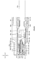
- the first holding portion 111a may be provided with a plurality of holding holes 111a1 arranged in two rows in the Z-Z' direction, at spaced intervals along X-X' direction. As best illustrated in Fig. 2C , each holding hole 111a1 extends through the first holding portion 111a in the Y-Y' direction.
- Each holding hole 111a1 has a shape conforming to the outer shapes of the intermediate portion 220a and the contact portion 210a of the corresponding first terminal 200a.
- Each holding hole 111a1 holds the intermediate portion 220a of a first terminal 200a and houses the contact portion 210a of the first terminal 200a.
- the at least one first terminal 200a may be insert-molded in the first holding portion 111a. In this case, the holding hole 111a1 is omitted.
- the second holding portion 112a holds the at least one second terminal 200b of the main body 110a.
- the second holding portion 112a may be an X'-direction side end portion of the main body 110a.
- the second holding portion 112a may be provided with at least one holding hole 112a1 to hold the second terminal 200b.
- the second holding portion 112a may be provided with a plurality of holding holes 112a1 arranged in two rows in the Z-Z' direction, at spaced intervals along X-X' direction.
- Each holding hole 112a1 has a similar configuration to that of the holding hole 111a1 and extends through the second holding portion 112a in the Y-Y' direction (see Fig. 2C showing a similar configuration).
- Each holding hole 112a1 holds the intermediate portion 220b of a second terminal 200b and houses the contact portion 210b of the second terminal 200b.
- the at least one second terminal 200b may be insert-molded in the second holding portion 112a. In this case, the holding hole 112a1 is omitted.
- Each opening 113a3 communicates with a housing portion 113a2.
- the front panel 113a1 is provided with a plurality of openings 113a3 arranged in two rows in the Z-Z' direction, at spaced intervals along the X-X' direction.
- each housing portion 113a2 may be a space between the first holding portion 111a and the second holding portion 112a joined by the joint portion 113a.
- a plurality of holding grooves 131a may be provided in the Z-direction-side surface of the second table 130a, at spaced intervals along the X-X' direction, and another plurality of holding grooves 131a may be provided in the Z'-direction-side surface of the second table 130a, at spaced intervals along the X-X' direction.
- the center plate 430a extends in the X-X' and Y-Y' directions.
- the center plate 430a is arranged on the Z-direction side relative to the first base 410a and the second base 420a.
- the center plate 430a may be arranged on the Z-direction side relative to, and between, the first base 410a and the second base 420a.
- the center plate 430a includes a first end 431a and a second end 432a.
- the first end 431a is the X-direction-side end of the center plate 430a.
- the second end 432a is the X'-direction-side end of the center plate 430a.
- the first base 410a is a part of the metal plate on the X-direction side relative to the center plate 430a (i.e. the first base 410a has a plate-like shape).
- the first base 410a extends in the X-X' and Y-Y' directions.
- the second base 420a is a part of the metal plate on the X'-direction side relative to the center plate 430a (i.e. the second base 420a has a plate-like shape).
- the second base 420a extends in the X-X' and Y-Y' directions.
- the first base 410a and the second base 420a are arranged side-by-side along the X-X' direction.
- the first base 410a and the second base 420a may be arranged at the same height position, or at different height positions, in the Z-Z' direction.
- the first base 410a includes a first end 411a, a second end 412a, and a third end 413a.
- the first end 411a is the X'-direction-side end of the first base 410a (the end at the side of the second base 420a).
- the second end 412a is the Y'-direction-side end of the first base 410a.
- the second end 412a may have a central part recessed in the Y direction or may be flat.
- the third end 413a is the X-direction-side end of the first base 410a.
- the second base 420a includes a first end 421a, a second end 422a, and a third end 423a.
- the first end 421a is the X-direction-side end of the second base 420a (the end at the side of the first base 410a).
- the second end 422a is the Y'-direction-side end of the second base 420a.
- the second end 422a may have a central part recessed in the Y direction or may be flat.
- the third end 423a is the X'-direction-side end of the second base 420a.
- the second inner plate 450a is a part between the center plate 430a and the second base 420a of the metal plate.
- the second inner plate 450a extends in the Z direction, from the first end 421a of the second base 420a to the second end 432a of the center plate 430a.
- the second inner plate 450a may be inclined in the X direction, the X' direction, the Y direction, the Y' direction, a direction including X- and Y-direction components, a direction including a X'- and Y-direction components, a direction including a X- and a Y'-direction components, or a direction including a X'- and a Y'-direction components.
- the second inner plate 450a may not be inclined, i.e. may extend at an angle of about 90 degrees to the second base 420a.
- the first holding plate 460a is a part at the Y'-direction side of the first base 410a of the metal plate.
- the first holding plate 460a is integral and contiguous with the second end 412a of the first base 410a.
- the first holding plate 460a includes a trunk 461a and a holding plate body 462a.
- the trunk 461a is a plate extending in the Y' direction from the second end 412a of the first base 410a.
- the holding plate body 462a is a plate integral and contiguous with the Y'-direction-side end of the trunk 461a. In planar development state, the holding plate body 462a is larger in X-X' direction dimension than the trunk 461a.
- the second holding plate 470a is a part at the Y'-direction side of the second base 420a of the metal plate.
- the second holding plate 470a is integral and contiguous with the second end 422a of the second base 420a.
- the second holding plate 470a includes a trunk 471a and a holding plate body 472a.
- the trunk 471a is a plate extending in the Y' direction from the second end 422a of the second base 420a.
- the holding plate body 472a is a plate integral and contiguous with the Y'-direction-side end of the trunk 471a. In planar development state, the holding plate body 472a is larger in X-X' direction dimension than the trunk 471a.
- the first shell 400a may further include a first outer plate 480a and a second outer plate 490a.
- the first outer plate 480a may only be provided at the first base 410a such as to be on the X-direction side relative to the first inner plate 450a with a space therebetween.
- the first outer plate 480a may be a part on the X-direction side of the first base 410a of the metal plate and extend in the Z direction from the third end 413a of the first base 410a.
- the first outer plate 480a may be a piece formed by cutting and raising a part of the first base 410a, or may be a member separately formed from the first base 410a to be fixed to the first base 410a.
- the first outer plate 480a may be inclined in the X direction, the X' direction, the Y direction, the Y' direction, a direction including X- and Y-direction components, a direction including a X'- and Y-direction components, a direction including a X- and a Y'-direction components, or a direction including a X'- and a Y'-direction components.
- the first outer plate 480a may not be inclined, i.e. may extend at an angle of about 90 degrees to the first base 410a.
- the first outer plate 480a, the first base 410a, and the first inner plate 440a may define a first housing space.
- the first outer plate 480a may include an outer plate body 481a and an extension plate 482a.
- the outer plate body 481a extends in the Z direction from the third end 413a of the first base 410a.
- the outer plate body 481a includes a Y-direction-side end.
- the extension plate 482a is integral and contiguous with the Y-direction-side end of the outer plate body 481a.
- the extension plate 482a is bent to the X'-direction side relative to the outer plate body 481a so as to partially cover the Y-direction side of the first housing space.
- a first gap is left between the extension plate 482a and the first inner plate 440a.
- the second outer plate 490a may only be provided at the second base 420a such as to be on the X-direction side relative to the second inner plate 460a with a space therebetween.
- the second outer plate 490a may be a part on the X'-direction side of the second base 420a of the metal plate and extend in the Z direction from the third end 423a of the second base 420a.
- the second outer plate 490a may be a piece formed by cutting and raising a part of the second base 420a, or may be a member separately formed from the second base 420a to be fixed to the second base 420a.
- the second outer plate 490a may be inclined in the X direction, the X' direction, the Y direction, the Y' direction, a direction including X- and Y-direction components, a direction including a X'- and Y-direction components, a direction including a X- and a Y'-direction components, or a direction including a X'- and a Y'-direction components.
- the second outer plate 490a may not be inclined, i.e. may extend at an angle of about 90 degrees to the second base 420a.
- the second outer plate 490a, the second base 420a, and the second inner plate 450a may define a second housing space.
- the extension plate 492a is integral and contiguous with the Y-direction-side end of the outer plate body 491a.
- the extension plate 492a is bent to the X-direction side relative to the outer plate body 491a so as to partially cover the Y-direction side of the second housing space.
- a second gap is left between the extension plate 492a and the second inner plate 450a.
- the first cable 300a includes an outer insulator 310a, a shield conductor (not shown), and at least one transmission wire 320a.
- the outer insulator 310a is a tuboid sheath.
- the shield conductor, tuboid braided conductive wires or a helically wound metal foil tape, is arranged inside the outer insulator 310a.
- the transmission wire(s) 320a is arranged inside the shield conductor.
- the Y-direction-side end portion of the outer insulator 310a is cut off such as to expose the Y-direction-side end portion end portion of the shield conductor.
- Around the exposed shield conductor is wound the holding plate body 462a of the first holding plate 460a for electrically connection therebetween (see Figs.
- the Y-direction-side end portion of the transmission wire 320a protrudes in the Y direction from the shield conductor.
- the protruding portion of each transmission wire 320a (hereinafter referred to as the protruding portion) is cut off at its distal end such as to expose the core wire inside the transmission wire 320a.
- the protruding portion of each transmission wire 320a passes through the first housing space and the first gap, and the core wire of each transmission wire 320a is electrically connected to the tail 230a of a first terminal 200a.
- Figs. 2A to 2C , 2G, and 2H show only the outline of the section of the first cable 300a.
- Figs. 4A and 4B show the holding plate body 462a before being wound around the shield conductor.
- the second cable 300b has a similar configuration to that of the first cable 300a.
- the second cable 300b includes an outer insulator 310b, a shield conductor (not shown), and at least one transmission wire 320b.
- the holding plate body 472a of the second holding plate 470a is wound around and electrically connected to the exposed portion of the shield conductor (see Figs. 2A , 2B , 2H , 3A , and 3B ).
- the protruding portion of each transmission wire 320b passes through the second housing space and the second gap, and the core wire of each transmission wire 320b is electrically connected to the tail 230b of a second terminal 200b.
- Figs. 2A , 2B , 2G, and 2H show only the outline of the section of the second cable 300b.
- Figs. 4A and 4B show the holding plate body 472a before being wound around the shield conductor.
- the second shell 400b is formed by press-forming a single metal plate.
- the second shell 400b includes a shell body 410b and a block portion 420b.
- the shell body 410b is a tube extending in the Y-Y' direction and arranged on the Y-direction side relative to the first shell 400a.
- the shell body 410b has an inner shape conforming to the outer shape of the body 100a.
- the shell body 410b houses the body 100a.
- the shell body 410b includes a first plate on the Z' -direction side, a second plate on the X-direction side, a third plate on the X'-direction side and a fourth plate on the Z-direction side.
- the block portion 420b is a plate extending in the Y' direction from the fourth plate of the shell body 410b.
- the block portion 420b is arranged in abutment with the center plate 430a of the first shell 400a from the Z-direction side or in spaced relation in the Z-Z' direction to the center plate 430a.
- the block portion 420b blocks the first housing space and the second housing space of the first shell 400a from the Y-direction side.
- the block portion 420b may include a center portion 421b, a first facing portion 422b, and a second facing portion 423b. As best illustrated in Fig.
- the second facing portion 423b is in facing relation to and in spaced relation in the Z-Z' direction to the second base 420a of the first shell 400a and blocks the second housing space from the Z-direction side.
- the second facing portion 423b may be in abutment with the second outer plate 490a of the first shell 400a. If the second outer plate 490a is omitted, the second housing space may preferably be defined by the second base 420a, the second inner plate 450a, and the second facing portion 423b.
- the first facing portion 422b includes an X-direction-side end and an Y'-direction-side end.
- the second facing portion 423b includes an X'-direction-side end and an Y'-direction-side end.
- At least one of the first outer plate 480a and the second outer plate 490a of the first shell 400a may be provided with a third engaging portion.
- At least one of the first facing portion 422b and the second facing portion 423b of the block portion 420b of the second shell 400b may be provided with a fourth engaging portion.
- One of the third engaging portion and the fourth engaging portion may include may include an engaging protrusion, and the other may include an engaging hole to engage with the engaging protrusion.
- the first outer plate 480a may include a third engaging portion 483a
- the second outer plate 490a may include a third engaging portion 493a.
- the third engaging portion 483a includes an engaging protrusion of a plate-like shape, which is formed by cutting a part of the outer plate body 481 a and bending the cut part to the X direction.
- the third engaging portion 493a includes an engaging portion of a plate-like shape, which is formed by cutting a part of the outer plate body 491a and bending the cut part in the X' direction.
- the block portion 420b includes a pair of fourth engaging portions 430b (one and the other fourth engaging portions 430b).
- At least one of the first base 410a and the second base 420a of the first shell 400a may be provided with a fifth engaging portion.
- the shell body 410b of the second shell 400b may be provided with a sixth engaging portion.
- One of the fifth engaging portion and the sixth engaging portion may include an engaging protrusion, and the other may include an engaging hole to engage with the engaging protrusion.
- the second shell 400b may include a pair of sixth engaging portions 460b.
- Each sixth engaging portion 460b includes an arm, which extends in the Y' direction from the first plate of the shell body 410b, and an engaging protrusion provided at the arm.
- the first shell 400a includes a fifth engaging portion 414a and a fifth engaging portion 424a.
- the fifth engaging portion 414a includes an engaging hole in the first base 410a.
- the fifth engaging portion 424a includes an engaging hole in the second base 420a. The engaging holes of the fifth engaging portion 414a and the fifth engaging portion 424a are engaged with the respective engaging protrusions of the sixth engaging portions 460b.
- each sixth engaging portion may include an engaging hole instead of the engaging protrusion.
- the engaging hole of each sixth engaging portion may be provided at the arm or at the first plate of the shell body 410b. In the latter case, the arm is omitted.
- each fifth engaging portion may include engaging protrusions of a plate-like shape, which is formed by cutting and bending parts of the first base 410a and the second base 420a. The engaging protrusions of the fifth engaging portions are engaged with the respective engaging holes of the sixth engaging portions.
- the first holding plate 460a of the first shell 400a is curved so as to be wound around the cover body 442b and the exposed shield conductor of the first cable 300a as best illustrated in Fig. 2H .
- the second cover 450b includes a base 451b and a cover body 452b.
- the base 451b is a plate extending in the Y' direction from the Y'-direction-side end of the second facing portion 423b.
- the cover body 452b is a plate of an arc shape integral and contiguous with the Y'-direction-side end of the base 451b.
- the cover body 452b partially covers the exposed shield conductor of the second cable 300b. If the second shell 400b includes the second cover 450b, the second holding plate 470a of the first shell 400a is curved so as to be wound around the cover body 452b and the exposed shield conductor of the second cable 300b as best illustrated in Fig. 2H .
- Each third terminal 200c is constituted by a metal plate and held by the body 100b. As each third terminal 200c may have a similar configuration to that of a first terminal 200a, as best illustrated in Fig. 2D , it will not be described.
- the third terminal 200c includes a contact portion 210c, an intermediate portion 220c, and a tail 230c.
- the body 100b is formed of insulation resin. As best illustrated in Figs. 6A and 6B , the body 100b includes a main body 110b.
- the main body 110b is a rectangular block.
- the main body 110a has an outer shape conforming to the shape of the housing portion 113a2 of the body 100a.
- the main body 110a is housed in the housing portion 113a2 of the body 100a.
- the body 100b is housed, together with the body 100a, in the shell body 410b of the second shell 400b.
- the main body 110b holds the at least one third terminal 200c.
- the main body 110b may have at least one holding hole 111b.
- the main body 110b may be provided with a plurality of holding holes 111b arranged in two rows in the Z-Z' direction, at spaced intervals along the X-X' direction. As best illustrated in Fig. 2D , each holding hole 111b extends through the main body 110b in the Y-Y' direction.
- Each holding hole 111b has a shape conforming to the outer shape of the intermediate portion 220c of a third terminal 200c.
- Each holding hole 111b holds the intermediate portion 220c of a third terminal 200c and houses the contact portion 210c of the third terminal 200c.
- Each holding hole 111b communicates with an opening 113a3 of the body 100a.
- the at least one third terminal 200c may be insert-molded in the main body 110b. In this case, the holding hole 111b is omitted.
- the main body 110b further includes an end face on the X-direction side and an end face on X'-direction side. As best illustrated in Figs. 6A and 6B , the end faces of the X- and X'- direction sides of the main body 110b may each be provided with an engaging recess 112b.
- the body 100b may further include a table 120b.
- the table 120b extends in the Y' direction from the Y'-direction-side end of the main body 110b.
- the table 120b may only be able to support the tail 230c of the at least one third terminal 200c.
- the table 120b may include at least one holding groove 121b.
- Each holding groove 121b is provided in the table 120b such as to communicate with a holding hole 111b.
- Each holding groove 121b houses and supports a tail 230c. As best illustrated in Fig.
- a plurality of holding grooves 121b may be provided in the Z-direction-side face of the table 120b, at spaced intervals along the X-X' direction, and another plurality of holding grooves 121b may be provided in the Z'-direction-side face of the first table 120a, at spaced intervals along the X-X' direction.
- the third shell 400c is formed by press-forming a single metal plate.
- the third shell 400c includes a shell body 410c and a third holding plate 420c.
- the shell body 410c is a tube extending in the Y-Y' direction and arranged between the first inner plate 440a and the second inner plate 450a of the first shell 400a (see Fig. 2G ).
- the shell body 410c includes a first plate 411c on the Z'-direction side, a second plate 412c on the X-direction side, a third plate 413c on the X'-direction side, and a fourth plate on the Z-direction side.
- the first plate 411c is arranged between the first inner plate 440a and the second inner plate 450a or between the first base 410a and the second base 420a. In Fig. 2G , the first plate 411c is arranged between the first base 410a and the second base 420a.
- the first plate 411c includes an X-direction-side end, an X'-direction-side end, and a Y'-direction-side end.
- the fourth plate 414c is arranged in abutment with the center plate 430a of the first shell 400a from the Z'-direction side or arranged to face the center plate 430a of the first shell 400a with a space therebetween in the Z-Z' direction. In Fig.
- the fourth plate 414c is in abutment (in surface contact) with the center plate 430a.
- the fourth plate 414c may engage with the center plate 430a.
- the fourth plate 414c includes an X-direction-side end and an X'-direction-side end.
- the second plate 412c integrally interjoins the X-direction-side end of the first plate 411c and the X-direction-side end of the fourth plate 414c.
- the second plate 412c is arranged in abutment with the first inner plate 440a of the first shell 400a or arranged to face the first inner plate 440a of the first shell 400a with a space therebetween.
- the second plate 412c is in abutment (in surface contact) with the first inner plate 440a.
- the second plate 412c may engage with the first inner plate 440a.
- the third plate 413c integrally interjoins the X'-direction-side end of the first plate 411c and the X'-direction-side end of the fourth plate 414c.
- the third plate 413c is arranged in abutment with the second inner plate 450a of the first shell 400a or arranged to face the second inner plate 450a of the first shell 400a with a space therebetween.
- the third plate 413c is in abutment with the second inner plate 450a.
- the third plate 413c may engage with the second inner plate 450a.
- the second plate 412c may further include a Y-direction-side end, and the third plate 413c may include a Y-direction-side end.
- the third holding plate 420c is provided at the first plate 411c.
- the third holding plate 420c is arranged between the first holding plate 460a and the second holding plate 470a of the first shell 400a (see Fig. 2H ).
- the third holding plate 420c includes a trunk 421c and a holding plate body 422c.
- the trunk 421c is a plate extending in the Y' direction from the Y'-direction-side end of the first plate 411c.
- the holding plate body 422c is a plate integral and contiguous with the Y'-direction-side end of the trunk 421c. In planar development state, the holding plate body 422c is larger in X-X' direction dimension than the trunk 421c.
- the third shell 400c may further include a pair of shield plates 430c (one and the other shield plates 430c).
- the one shield plate 430c is a plate extending in the Y direction from the Y-direction-side end of the second plate 412c.
- the other shield plate 430c is a plate extending in the Y direction from the Y-direction-side end of the third plate 413c. It is preferable that distal end portions (end portions on the Y-direction side) of the shield plates 430c be respectively in abutment with at least the end faces of the X- and X'- direction sides of the main body 110b of the body 100b.
- the second shell 400b may further include a seventh engaging portion.
- the third shell 400c may further include an eighth engaging portion.
- One of the seventh engaging portion and the eighth engaging portion may include an engaging protrusion, and the other may have an engaging hole to engage with the engaging protrusion.
- the first plate of the shell body 410b of the second shell 400b may include a pair of seventh engaging portions 470b.
- the seventh engaging portions 470b may each include an engaging protrusion of a plate-like shape, which is formed by cutting and bending a part of the first plate of the shell body 410b such that the cut part extends in the Z' direction from the first plate.
- the third shell 400c includes an eighth engaging portion 440c.
- the eighth engaging portion 440c includes an engaging plate and an engaging hole.
- the engaging plate of the eighth engaging portion 440c extends in the Y direction from the Y-direction-side end of the first plate 411c of the shell body 410c.
- the engaging hole of the eighth engaging portion 440c is provided in the engaging plate. As shown in Fig. 3B , the engaging protrusions of the seventh engaging portions 470b are engaged with the engaging hole of the eighth engaging portion 440c from the Z-direction side.
- the eighth engaging portion may include, in place of the engaging hole, an engaging protrusion on the engaging plate.
- the seventh engaging portion may include an engaging hole in the first plate of the shell body 410b, and the engaging hole may engage with the engaging protrusion of the eighth engaging portion.
- the third shell 400c may further include a ninth engaging portion.
- the ninth engaging portion may only engage with the center plate 430a of the first shell 400a.
- a ninth engaging portion 450c is provided at the fourth plate 414c of the shell body 410c.
- the ninth engaging portion 450c includes an engaging plate and an engaging protrusion.
- the engaging plate of the ninth engaging portion 450c extends in the Y direction from the Y-direction-side end of the fourth plate 414c.
- the engaging protrusion of the ninth engaging portion 450c is a plate formed by cutting and bending a part of the engaging plate such that the cut part extends in the Z direction from the engaging plate.
- the engaging protrusion of the ninth engaging portion 450c engage with the Y-direction-side end of the center plate 430a of the first shell 400a.
- the first shell 400a may further include a tenth engaging portion.
- One of the ninth engaging portion and the tenth engaging portion may include an engaging protrusion, and the other may have an engaging hole to engage with the engaging protrusion.
- the holding plate body 422c of the third holding plate 420c of the third shell 400c for electrically connection therebetween (see Figs. 2A , 2B , 2D , 2H , 3A , and 3B ).
- the Y-direction-side end portion of the transmission wire 320c protrudes in the Y direction from the shield conductor.
- the protruding portion of each transmission wire 320c (hereinafter referred to as the protruding portion) is cut off at its distal end such as to expose the core wire inside the transmission wire 320c.
- each transmission wire 320c passes through the shell body 410c of the third shell 400c, and the core wire of each transmission wire 320a is electrically connected to the tail 230c of a third terminal 200c.
- the core wires of each transmission wire 320a may be connected to the respective tails 230c of four third terminals 200c.
- Figs. 2A , 2B , 2D , 2G, and 2H show only the outline of the section of the third cable 300c.
- Figs. 6A and 6B show the holding plate body 422c before being wound around the shield conductor.
- the third shell 400c may further include a third cover 460c.
- the third cover 460c is provided at the fourth plate 414c of the shell body 410c of the third shell 400c.
- the third cover 460c includes a base 461c and a cover body 462c.
- the base 461c is a plate extending in the Y' direction from the Y'-direction end of the fourth plate 414c.
- the cover body 462c is a plate of an arc shape that is integral and contiguous with the Y'-direction-side end of the base 461c.
- the cover body 462c partially covers the exposed shield conductor of the third cable 300c. If the third shell 400c includes the third cover 460c, the third holding plate 420c of the third shell 400c is curved so as to be wound around the cover body 462c and the exposed shield conductor of the third cable 300c.
- the connector C may further include an outer case 500.
- the outer case 500 is formed of insulation resin.
- the outer case 500 includes a front portion and a rear portion.
- the outer case 500 further includes a first housing portion 510 and a second housing portion 520.
- the first housing portion 510 is a hole in the front portion of the outer case 500 and open in the Y direction.
- the first housing portion 510 has a shape conforming to the outer shape of the shell body 410b of the second shell 400b.
- the first housing portion 510 houses the shell body 410c, the shield plate 430c of the third shell 400c, the body 100a, the body 100b, the first terminal(s) 200a, the second terminal(s) 200b, and the third terminal(s) 200c.
- the second housing portion 520 is a hole in the rear portion of the outer case 500, and the hole communicates with the first housing portion 510 and is open in the Y' direction.
- the second housing portion 520 has a shape conforming to the outer shape of the combination of the block portion 420b and the first shell 400a.
- the second housing portion 520 houses the block portion 420b, the first shell 400a, a part of the third shell 400c other than the shield plate 430c, a Y-direction-side end portion of the first cable 300a, a Y-direction-side end portion of the second cable 300b, and a Y-direction-side end portion of the third cable 300c.
- the connector C may further include a cap 600.
- the cap 600 is formed of insulation resin.
- the cap 600 is fitted in the second housing portion 520 such as to block the second housing portion 520 of the outer case 500 from the Y'-direction side.
- the cap 600 is located on the Y'-direction side relative to the first shell 400a and the third shell 400c.
- the cap 600 is provided with three holding grooves 610. The respective holding grooves 610 partially hold the first cable 300a, the second cable 300b, and the third cable 300c.
- the body 100a, the first terminal(s) 200a, and the second terminal(s) 200b are prepared.
- Each first terminal 200a is inserted into a holding hole 111a1 of the body 100a from the Y'-direction side.
- This results in that the intermediate portion 220a and the contact portion 210a of each first terminal 200a are housed in a holding hole 111a1 of the body 100a, and the tail 230a of each first terminal 200a is housed in a holding groove 121a of the body 100a.
- Each second terminals 200b is inserted into a holding hole 112a1 of the body 100a from the Y'-direction side.
- the second shell 400b is prepared.
- the body 100b is fitted into the shell body 410b of the second shell 400b from the Y'-direction side. This results in that the body 100b, the first terminal(s) 200a, and the second terminal(s) 200b are arranged inside the shell body 410b.
- the first cover 440b of the second shell 400b is brought into contact with the exposed shield conductor of the first cable 300a.
- the second cover 450b of the second shell 400b is brought into contact with the exposed shield conductor of the second cable 300b.
- the center plate 430a, the first outer plate 480a, and the second outer plate 490a of the first shell 400a is brought into abutment with the block portion 420b of the second shell 400b from the Z'-direction side, and the block portion 420b blocks the first housing space and the second housing space of the first shell 400a from the Z-direction side.
- the first engaging portion 441a of the first shell 400a is engaged with the second engaging portion 424b of the block portion 420b from the Z'-direction side
- the first engaging portion 451a of the first shell 400a is engaged with the second engaging portion 425b of the block portion 420b from the Z'-direction side.
- the third shell 400c is prepared.
- the third shell 400c is a state in which the shell body 410c is in planar development state.
- the shield plate 430c on the X'-direction side of the third shell 400c is engaged with the engaging recess 112b on the X'-direction side of the body 100b.
- the shell 400c of the third shell 400c is formed into a tubular shape. This forming results in the following arrangements 7) to 10).
- the shield plate 430c on the X-direction side of the third shell 400c is engaged with the engaging recess 112b on the X-direction side of the body 100b.
- the transmission wire(s) 320c of the third cable 300c is arranged to pass through the shell body 410c.
- the third cover 460c of the third shell 400c is brought into contact with the exposed shield conductor of the third cable 300c.
- the third holding plate 420c of the third shell 400c is arranged to face the exposed shield conductor of the third cable 300c.
- the body 100b, the third terminal(s) 200c and the distal ends of the pair of the shield plates 430c of the third cable 300c are arranged inside the shell body 410b of the second shell 400b of the first unit C1.
- the third holding plate 420c of the third shell 400c is arranged between the first holding plate 460a and the second holding plate 470a of the first shell 400a.
- the engaging protrusions of each seventh engaging portion 470b of the second shell 400b is engaged with an engaging hole of the eighth engaging portion 440c of the third shell 400c.
- the ninth engaging portion 450c of the third shell 400c is engaged with the Y-direction-side end of the center plate 430a of the first shell 400a. In this way, the second unit C2 is attached to the first unit C1.
- the first shell 400a in three-dimensional state has a decreased dimension in the X-X' direction for the following reasons.
- the first shell 400a in three-dimensional state is configured such that: the center plate 430a is arranged on the Z-direction side relative to the first base 410a and the second base 420a; the first inner plate 440a extends from the first end 411a of the first base 410a to the first end 431a of the center plate 430a; and the second inner plate 450a extends from the first end 421a of the second base 420a to the second end 432a of the center plate 430a.
- This configuration decreases the space in the X-X' direction between the first base 410a and the second base 420a, thereby decreasing the X-X' direction dimension of the first shell 400a in three-dimensional state, and accordingly, decreasing the X-X' direction dimension of the connector C.
- the first shell 400a in planar development state has an increased space in the X-X' direction between the first holding plate 460a and the second holding plate 470a.
- the first shell 400a in planar development state is configured such that the center plate 430a, the first inner plate 440a, the second inner plate 450a, the first base 410a and the second base 420a are aligned along the X-X' direction.
- Such alignment results in that the space in the X-X' direction between the first base 410a and the second base 420a increases by the sum of the X-X' direction dimensions of the center plate 430a, the first inner plate 440a and the second inner plate 450a.
- the existence of the second unit C2 does not result in increase in X-X' direction dimension of the connector C for the following reason.
- the body 100b of the second unit C2 is housed in the housing portion 113a2 of the body 100a of the first unit C1, and the shell body 410c of the third shell 400c of the second unit C2 is arranged between the first inner plate 440a and the second inner plate 450a of the first shell 400a of the first unit C1, and the third holding plate 420c of the third shell 400c is arranged between the first holding plate 460a and the second holding plate 470a of the first shell 400a. Therefore, attaching the second unit C2 to the first unit C1 does not result in an increased X-X' direction dimension of the connector.
- the shield case S of the connector C has an improved strength. This is because the shell body 410c of the third shell 400c abuts the center plate 430a, the first inner plate 440a, and the second inner plate 450a of the first shell 400a from inside and also fits inside the combination of the center plate 430a, the first inner plate 440a and the second inner plate 450a (a fitting structure). Further, the first shell 400a, the second shell 400b and the third shell 400c are engaged with each other as described above. Therefore, a load due to prying of the first cable 300a, the second cable 300b, and/or the third cable 300c in the X-X' direction will spread over the fitting structure.
- the connector C has a decreased number of components.
- the first terminal 200a and the second terminal 200b are held by a single body 100a.
- the body 100a and the body 100b holding the third terminal(s) 200c are housed in the shell body 410b of a single second shell 400b. It is therefore possible to decrease the number of the components for the connector C, compared to a connector in which the first terminal(s) 200a, the second terminal(s) 200b, and the third terminal(s) 200c are respectively held by different bodies and the bodies are respectively housed in different shells.
- the first engaging portion 441a of the first shell 400a is engaged with the second engaging portion 424b of the second shell 400b and the first engaging portion 451a of the first shell 400a is engaged with the second engaging portion 425b of the second shell 400b, while the third engaging portion 483a and the third engaging portion 493a of the first shell 400a are respectively engaged with the engaging holes of the fourth engaging portion 430b of the second shell 400b.
- the shield case of the invention may be modified in any manner as long as the shield case includes at least the first shell of any of the above aspects or a first shell as described below.
- the first shell of the shield case of the invention may be modified in any manner as long as the first shell includes the first base, the second base, the center plate, the first inner plate, the second plate, the first holding plate, and the second holding plate of any of the above aspects.
- the first shell may include a plurality of shell parts adjacent to each other in the X-X' direction.
- the shell parts includes two shell parts adjacent to each other. The two shell parts share the first base of any of the above aspects.
- the center plate of one of the shell parts and the center plate of the other shell part are arranged with a space therebetween in the X-X' direction.
- the first inner plate of the one shell part extends from the X-direction-side end of the shared first base to the X'-direction-side end of the center plate of the one shell part.
- the first inner plate of the other shell part extends from X'-direction-side end of the shared first base to X-direction-side end of the center plate of the other shell part.
- each shell part may have the same configuration as the first shell of any of the above aspects; however the first outer plate is omitted.
- the first shell of the shield case of the invention may be provided without the first outer plate, the second outer plate, the first engaging portion, the third engaging portion, the fifth engaging portion, and/or the tenth engaging portion.
- the shield case of the invention may include at least the first shell and the block portion of any of the above aspects. In this case, the block portion is not part of the second shell, and the shell body of the second shell is omitted.
- the shield case of the invention may include at least the first shell and the shell body of the second shell of any of the above aspects. In this case, the block portion of the second shell is omitted.
- the shell body of the second shell of the invention may be arranged on the Y- or Y'-direction side relative to the first shell.
- the second shell or the block portion that is not part of the second shell of the shield case of the invention is not limited to one formed by press-forming a metal plate.
- the second shell or the block portion that is not part of the second shell of the shield case of the invention may be constituted by a metal plate formed by casting. It should be noted that the second shell of the shield case of the invention may be provided without the second engaging portion, the fourth engaging portion, the first cover, the second cover, the sixth engaging portion, and/or the seventh engaging portion.
- the third shell of the shield case of the invention may be omitted. If the third shell is omitted, it is preferable that the protruding portion(s) of the transmission wire(s) of the third cable passes through between the first inner plate and the second inner plate of the first shell of any of the above aspects.
- the third shell of the shield case of the invention may include the first plate and the third holding plate of the third shell of any of the above aspects. In this case, the second to the fourth plates of the shell body of the third shell are omitted.
- the shell body of the third shell of the shield case of the invention may include the first plate, the second plate, and the third plate of the third shell of any of the above aspects. In this case, the fourth plate of the shell body of the third shell is omitted.
- the third shell of the shield case of the invention is not limited to a metal plate formed by press-forming.
- the third shell of the shield case of the invention may be constituted by a metal plate formed by casting. It should be noted that the third shell of the shield case of the invention may be provided without the shield plate, the eighth engaging portion, the ninth engaging portion, and/or the third cover.
- the third cover of the invention may be provided at the block portion of any of the above aspects.
- the first cable of the invention may only be electrically connected to the first terminal(s) of any of the above aspects.
- the first cable may be electrically connected to the first terminal(s) via connection means, such as a substrate, a cable(s), or a pin(s).
- the second cable of the invention may only be electrically connected to the second terminal(s) of any of the above aspects.
- the second cable may be electrically connected to the second terminal(s) via connection means, such as a substrate, a cable(s), or a pin(s).
- the third cable of the invention may only be electrically connected to the third terminal(s) of any of the above aspects.
- the third cable may be electrically connected to the third terminal(s) via a connection means, such as a substrate, a cable(s), or a pin(s).
- the connector of the invention may be modified in any manner as long as the connector includes the first terminal(s), the second tenninal(s), the shield case, the first cable, and the second cable of any of the above aspects.
- the connector of the invention may further include the first body to hold the first terminal(s) of any of the above aspects and the second body to hold the second terminal (s) of any of the above aspects. In this case, the second unit may be omitted.
- the connector of the invention may further include the first body to hold the first terminal(s) of any of the above aspects, the second body to hold the second terminal(s) of any of the above aspects, and the third body to hold the third terminal(s) of any of the above aspects.
- the connector of the invention may further include the first body to hold the first terminal(s) and the second terminal(s) of any of the above aspects, and the third body to hold the third terminal(s) of any of the above aspects.
- the connector of the invention may further include the first body to hold the first terminal(s), the second terminal(s), and the third terminal(s) of any of the above aspects.
- the first body of any of the above aspects may be arranged on the first base of the first shell of any of the above aspects, or may be housed inside the second shell of any of the above aspects. In the former case, it is preferable to omit the shell body of the second shell.
- the second body of any of the above aspects may be arranged on the second base of the first shell of any of the above aspects, or may be housed inside the second shell of any of the above aspects. In the former case, it is preferable to omit the shell body of the second shell.
- the third body of any of the above aspects may be arranged between the first inner plate and the second inner plate of the first shell of any of the above aspects, or may be arranged on the first plate of the third shell of any of the above aspects, or may be housed inside the second shell of any of the above aspects. In the former two cases, it is preferable to omit the shell body of the second shell.
- the first direction (including the X-X' direction) of the invention may be defined in any manner as long as the first direction corresponds to the alignment direction of the first base and the second base of the first shell of the invention.
- the second direction (including the Y-Y' direction) of the invention may be defined in any manner as long as the second direction crosses the first direction.
- the third direction (including the Z-Z' direction) of the invention may be defined in any manner as long as the third direction crosses the first and second directions and is located on a different plane from the plane where the first and second directions are located.
Landscapes
- Details Of Connecting Devices For Male And Female Coupling (AREA)
- Details Of Aerials (AREA)
Applications Claiming Priority (2)
| Application Number | Priority Date | Filing Date | Title |
|---|---|---|---|
| JP2015102167A JP2016219221A (ja) | 2015-05-19 | 2015-05-19 | シールドケース及びこれを備えたコネクタ |
| PCT/JP2016/064683 WO2016186120A1 (ja) | 2015-05-19 | 2016-05-18 | シールドケース及びこれを備えたコネクタ |
Publications (2)
| Publication Number | Publication Date |
|---|---|
| EP3300182A1 true EP3300182A1 (de) | 2018-03-28 |
| EP3300182A4 EP3300182A4 (de) | 2018-03-28 |
Family
ID=57320239
Family Applications (1)
| Application Number | Title | Priority Date | Filing Date |
|---|---|---|---|
| EP16796513.6A Withdrawn EP3300182A4 (de) | 2015-05-19 | 2016-05-18 | Abschirmungsgehäuse und verbinder damit |
Country Status (5)
| Country | Link |
|---|---|
| US (1) | US10020618B2 (de) |
| EP (1) | EP3300182A4 (de) |
| JP (1) | JP2016219221A (de) |
| CN (1) | CN107615596A (de) |
| WO (1) | WO2016186120A1 (de) |
Cited By (1)
| Publication number | Priority date | Publication date | Assignee | Title |
|---|---|---|---|---|
| EP3340395B1 (de) * | 2016-12-22 | 2020-02-19 | Dai-Ichi Seiko Co., Ltd. | Verbinder und herstellungsverfahren dafür |
Families Citing this family (4)
| Publication number | Priority date | Publication date | Assignee | Title |
|---|---|---|---|---|
| CN107069340A (zh) * | 2017-06-13 | 2017-08-18 | 郑州德睿航联电子技术有限公司 | 一种航插屏蔽结构及使用该航插屏蔽结构的航插装置 |
| TWI740050B (zh) * | 2018-06-01 | 2021-09-21 | 日商島野股份有限公司 | 用於人力交通工具之電纜線總成 |
| CN110994286A (zh) * | 2019-11-14 | 2020-04-10 | 联想(北京)有限公司 | 一种射频连接装置及电子设备 |
| DE202020106373U1 (de) * | 2020-11-06 | 2020-11-19 | Md Elektronik Gmbh | Erdungsschelle mit Verdrehschutz |
Family Cites Families (16)
| Publication number | Priority date | Publication date | Assignee | Title |
|---|---|---|---|---|
| US3149897A (en) * | 1961-08-29 | 1964-09-22 | Hans G Martineck | Printed cable connector |
| US5389006A (en) * | 1993-08-13 | 1995-02-14 | Burndy Corporation | Lightweight entertainment connector |
| JPH10241791A (ja) | 1996-12-25 | 1998-09-11 | Harness Sogo Gijutsu Kenkyusho:Kk | コネクタ及びその取付構造 |
| US6004160A (en) * | 1997-03-25 | 1999-12-21 | The Whitaker Corporation | Electrical connector with insert molded housing |
| US6323430B1 (en) * | 1999-07-28 | 2001-11-27 | Itt Manufacturing Enterprises, Inc. | S-shaped cable holding clamp with grounding |
| JP3926078B2 (ja) | 2000-01-05 | 2007-06-06 | 株式会社オートネットワーク技術研究所 | シールド電線の端末接続構造 |
| US6547605B2 (en) * | 2001-07-20 | 2003-04-15 | Delphi Technologies, Inc. | Flex circuit electrical connector |
| US6489563B1 (en) | 2001-10-02 | 2002-12-03 | Hon Hai Precision Ind. Co., Ltd. | Electrical cable with grounding sleeve |
| JP4091376B2 (ja) * | 2002-08-07 | 2008-05-28 | 株式会社フジクラ | 伝送ケーブルおよび伝送ケーブルとコネクタとの接続方法 |
| JP2004079377A (ja) * | 2002-08-20 | 2004-03-11 | Auto Network Gijutsu Kenkyusho:Kk | 多芯型ケーブルの端末接続構造 |
| JP4652742B2 (ja) | 2004-08-11 | 2011-03-16 | 日本圧着端子製造株式会社 | コネクタ |
| JP4864340B2 (ja) | 2005-04-14 | 2012-02-01 | 日本圧着端子製造株式会社 | 同軸ケーブルの電気コネクタ |
| CN102280754B (zh) * | 2010-06-10 | 2013-06-12 | 富士康(昆山)电脑接插件有限公司 | 线缆连接器组件 |
| WO2013006592A2 (en) | 2011-07-07 | 2013-01-10 | Molex Incorporated | High performance cable with faraday ground sleeve |
| JP6114672B2 (ja) * | 2013-09-27 | 2017-04-12 | ホシデン株式会社 | コネクタ |
| CN203983548U (zh) * | 2014-08-08 | 2014-12-03 | 莫列斯公司 | 电连接器及电连接器组合 |
-
2015
- 2015-05-19 JP JP2015102167A patent/JP2016219221A/ja active Pending
-
2016
- 2016-05-18 CN CN201680028689.6A patent/CN107615596A/zh active Pending
- 2016-05-18 EP EP16796513.6A patent/EP3300182A4/de not_active Withdrawn
- 2016-05-18 WO PCT/JP2016/064683 patent/WO2016186120A1/ja not_active Ceased
- 2016-05-18 US US15/573,175 patent/US10020618B2/en active Active
Cited By (1)
| Publication number | Priority date | Publication date | Assignee | Title |
|---|---|---|---|---|
| EP3340395B1 (de) * | 2016-12-22 | 2020-02-19 | Dai-Ichi Seiko Co., Ltd. | Verbinder und herstellungsverfahren dafür |
Also Published As
| Publication number | Publication date |
|---|---|
| WO2016186120A1 (ja) | 2016-11-24 |
| US20180069350A1 (en) | 2018-03-08 |
| EP3300182A4 (de) | 2018-03-28 |
| JP2016219221A (ja) | 2016-12-22 |
| CN107615596A (zh) | 2018-01-19 |
| US10020618B2 (en) | 2018-07-10 |
Similar Documents
| Publication | Publication Date | Title |
|---|---|---|
| EP3300182A1 (de) | Abschirmungsgehäuse und verbinder damit | |
| US6482045B2 (en) | Connector socket, connector plug and connector assembly | |
| US8025532B2 (en) | Connector and electronic equipment | |
| CN112714985B9 (zh) | 连接器 | |
| US9257797B2 (en) | Cable assembly having an improved circuit board | |
| US11303070B2 (en) | Connector and outer conductor | |
| EP3584891B1 (de) | Schirmanschluss und schildkabelanordnung mit klemme | |
| US12184004B2 (en) | Plug connector, receptacle connector and connector assembly with power supply function | |
| US10819071B2 (en) | Connector structure that is reconfigurable to accommodate either an STP cable or a UTP cable | |
| US10622731B2 (en) | Miniaturized cable connector assembly | |
| CN115832740B (zh) | 电连接器 | |
| US20090215315A1 (en) | Power connector with improved contacts | |
| US20060172589A1 (en) | Connector assembly having low profile | |
| US9979112B2 (en) | Press-type connector | |
| KR200499264Y1 (ko) | 개선된 접지 피스를 갖는 전기 커넥터 | |
| US7118428B2 (en) | Female terminal for the electrically conductive connection to a terminal pin, especially a flat-pin terminal | |
| US20250079767A1 (en) | Hybrid connector and connection structure of hybrid connectors including the same | |
| US12542407B2 (en) | Electrical connector with conductive terminals having improved structure | |
| US12237594B2 (en) | Electrical connector assembly having improved locking elements | |
| JP6735381B2 (ja) | コネクタ構造 | |
| US20260018836A1 (en) | Backplane connector with improved metal shield surrounding member | |
| JP2014056758A (ja) | カードエッジ型同軸コネクタ | |
| US6893287B2 (en) | Electrical connector assembly | |
| US11050179B2 (en) | Electrical connector having a contact formed of first and second contact parts coupled together | |
| KR20240033675A (ko) | 단자 소켓, 단자 핀, 단자 시스템 및 단자 조립체 |
Legal Events
| Date | Code | Title | Description |
|---|---|---|---|
| PUAI | Public reference made under article 153(3) epc to a published international application that has entered the european phase |
Free format text: ORIGINAL CODE: 0009012 |
|
| 17P | Request for examination filed |
Effective date: 20171129 |
|
| A4 | Supplementary search report drawn up and despatched |
Effective date: 20180216 |
|
| AK | Designated contracting states |
Kind code of ref document: A1 Designated state(s): AL AT BE BG CH CY CZ DE DK EE ES FI FR GB GR HR HU IE IS IT LI LT LU LV MC MK MT NL NO PL PT RO RS SE SI SK SM TR |
|
| AX | Request for extension of the european patent |
Extension state: BA ME |
|
| DAV | Request for validation of the european patent (deleted) | ||
| DAX | Request for extension of the european patent (deleted) | ||
| 17Q | First examination report despatched |
Effective date: 20200330 |
|
| STAA | Information on the status of an ep patent application or granted ep patent |
Free format text: STATUS: THE APPLICATION HAS BEEN WITHDRAWN |
|
| 18W | Application withdrawn |
Effective date: 20200422 |