EP3300648A2 - Appareil de traitement de surfaces se déplaçant automatiquement - Google Patents
Appareil de traitement de surfaces se déplaçant automatiquement Download PDFInfo
- Publication number
- EP3300648A2 EP3300648A2 EP17192561.3A EP17192561A EP3300648A2 EP 3300648 A2 EP3300648 A2 EP 3300648A2 EP 17192561 A EP17192561 A EP 17192561A EP 3300648 A2 EP3300648 A2 EP 3300648A2
- Authority
- EP
- European Patent Office
- Prior art keywords
- surface treatment
- housing part
- contact sensor
- treatment device
- housing
- Prior art date
- Legal status (The legal status is an assumption and is not a legal conclusion. Google has not performed a legal analysis and makes no representation as to the accuracy of the status listed.)
- Granted
Links
Images

Classifications
-
- A—HUMAN NECESSITIES
- A47—FURNITURE; DOMESTIC ARTICLES OR APPLIANCES; COFFEE MILLS; SPICE MILLS; SUCTION CLEANERS IN GENERAL
- A47L—DOMESTIC WASHING OR CLEANING; SUCTION CLEANERS IN GENERAL
- A47L9/00—Details or accessories of suction cleaners, e.g. mechanical means for controlling the suction or for effecting pulsating action; Storing devices specially adapted to suction cleaners or parts thereof; Carrying-vehicles specially adapted for suction cleaners
- A47L9/28—Installation of the electric equipment, e.g. adaptation or attachment to the suction cleaner; Controlling suction cleaners by electric means
-
- G—PHYSICS
- G05—CONTROLLING; REGULATING
- G05D—SYSTEMS FOR CONTROLLING OR REGULATING NON-ELECTRIC VARIABLES
- G05D1/00—Control of position, course, altitude or attitude of land, water, air or space vehicles, e.g. using automatic pilots
- G05D1/02—Control of position or course in two dimensions
- G05D1/021—Control of position or course in two dimensions specially adapted to land vehicles
- G05D1/0227—Control of position or course in two dimensions specially adapted to land vehicles using mechanical sensing means, e.g. for sensing treated area
-
- A—HUMAN NECESSITIES
- A01—AGRICULTURE; FORESTRY; ANIMAL HUSBANDRY; HUNTING; TRAPPING; FISHING
- A01D—HARVESTING; MOWING
- A01D34/00—Mowers; Mowing apparatus of harvesters
- A01D34/006—Control or measuring arrangements
- A01D34/008—Control or measuring arrangements for automated or remotely controlled operation
-
- A—HUMAN NECESSITIES
- A47—FURNITURE; DOMESTIC ARTICLES OR APPLIANCES; COFFEE MILLS; SPICE MILLS; SUCTION CLEANERS IN GENERAL
- A47L—DOMESTIC WASHING OR CLEANING; SUCTION CLEANERS IN GENERAL
- A47L11/00—Machines for cleaning floors, carpets, furniture, walls, or wall coverings
- A47L11/40—Parts or details of machines not provided for in groups A47L11/02 - A47L11/38, or not restricted to one of these groups, e.g. handles, arrangements of switches, skirts, buffers, levers
-
- A—HUMAN NECESSITIES
- A47—FURNITURE; DOMESTIC ARTICLES OR APPLIANCES; COFFEE MILLS; SPICE MILLS; SUCTION CLEANERS IN GENERAL
- A47L—DOMESTIC WASHING OR CLEANING; SUCTION CLEANERS IN GENERAL
- A47L11/00—Machines for cleaning floors, carpets, furniture, walls, or wall coverings
- A47L11/40—Parts or details of machines not provided for in groups A47L11/02 - A47L11/38, or not restricted to one of these groups, e.g. handles, arrangements of switches, skirts, buffers, levers
- A47L11/4002—Installations of electric equipment
- A47L11/4008—Arrangements of switches, indicators or the like
-
- A—HUMAN NECESSITIES
- A47—FURNITURE; DOMESTIC ARTICLES OR APPLIANCES; COFFEE MILLS; SPICE MILLS; SUCTION CLEANERS IN GENERAL
- A47L—DOMESTIC WASHING OR CLEANING; SUCTION CLEANERS IN GENERAL
- A47L11/00—Machines for cleaning floors, carpets, furniture, walls, or wall coverings
- A47L11/40—Parts or details of machines not provided for in groups A47L11/02 - A47L11/38, or not restricted to one of these groups, e.g. handles, arrangements of switches, skirts, buffers, levers
- A47L11/4061—Steering means; Means for avoiding obstacles; Details related to the place where the driver is accommodated
-
- A—HUMAN NECESSITIES
- A47—FURNITURE; DOMESTIC ARTICLES OR APPLIANCES; COFFEE MILLS; SPICE MILLS; SUCTION CLEANERS IN GENERAL
- A47L—DOMESTIC WASHING OR CLEANING; SUCTION CLEANERS IN GENERAL
- A47L9/00—Details or accessories of suction cleaners, e.g. mechanical means for controlling the suction or for effecting pulsating action; Storing devices specially adapted to suction cleaners or parts thereof; Carrying-vehicles specially adapted for suction cleaners
- A47L9/28—Installation of the electric equipment, e.g. adaptation or attachment to the suction cleaner; Controlling suction cleaners by electric means
- A47L9/2805—Parameters or conditions being sensed
-
- G—PHYSICS
- G05—CONTROLLING; REGULATING
- G05D—SYSTEMS FOR CONTROLLING OR REGULATING NON-ELECTRIC VARIABLES
- G05D1/00—Control of position, course, altitude or attitude of land, water, air or space vehicles, e.g. using automatic pilots
- G05D1/0055—Control of position, course, altitude or attitude of land, water, air or space vehicles, e.g. using automatic pilots with safety arrangements
- G05D1/0077—Control of position, course, altitude or attitude of land, water, air or space vehicles, e.g. using automatic pilots with safety arrangements using redundant signals or controls
-
- G—PHYSICS
- G05—CONTROLLING; REGULATING
- G05D—SYSTEMS FOR CONTROLLING OR REGULATING NON-ELECTRIC VARIABLES
- G05D1/00—Control of position, course, altitude or attitude of land, water, air or space vehicles, e.g. using automatic pilots
- G05D1/02—Control of position or course in two dimensions
- G05D1/021—Control of position or course in two dimensions specially adapted to land vehicles
- G05D1/0231—Control of position or course in two dimensions specially adapted to land vehicles using optical position detecting means
- G05D1/0234—Control of position or course in two dimensions specially adapted to land vehicles using optical position detecting means using optical markers or beacons
-
- A—HUMAN NECESSITIES
- A47—FURNITURE; DOMESTIC ARTICLES OR APPLIANCES; COFFEE MILLS; SPICE MILLS; SUCTION CLEANERS IN GENERAL
- A47L—DOMESTIC WASHING OR CLEANING; SUCTION CLEANERS IN GENERAL
- A47L2201/00—Robotic cleaning machines, i.e. with automatic control of the travelling movement or the cleaning operation
- A47L2201/04—Automatic control of the travelling movement; Automatic obstacle detection
Definitions
- the invention relates to an automatically moving surface treatment device, in particular a cleaning robot, with a device housing and a collision detection device for detecting a collision of the surface treatment device with an obstacle, wherein the collision detection device has at least one touch-sensitive contact sensor.
- Self-propelled surface handling equipment is well known. These are used, in particular, in the household sector for processing a surface, in particular for vacuuming and / or wiping floor coverings.
- Such surface treatment devices have, for orientation within an environment, for example, a distance measuring device, which measures distances to obstacles within the environment. From the measured distance values and, if appropriate, measured values of further sensors, an environment map is created, which is used for navigation and self-localization of the surface processing device within the environment.
- the distance measuring device also serves to detect obstacles within a travel path of the surface treatment device, so that obstacles within the environment can be avoided while avoiding a collision.
- the distance measuring device uses, for example, a triangulation measuring method in which light signals are emitted by a light source. The at one Obstruction reflected light signals are then received by a sensor of the distance measuring device and preferably processed within the surface treatment device. Depending on the processing result, a control signal is generated, for example for stopping a movement of the surface treatment device and / or for initiating an evasive maneuver or the like.
- the publication DE 10 2013 106 294 A1 discloses, for example, a surface treatment device with a distance measuring device which is protected by a housing part formed on the upper side of the device housing, which has a contact sensor.
- the contact sensor can detect a collision of the housing part with an obstacle in the horizontal direction of travel. In this way, an impact of the surface treatment device, namely the aforementioned housing part, can be detected on an obstacle located in front of the distance measuring device.
- the travel of the surface treatment device can then be changed so that the surface processing device bypasses the obstacle and thus damage to the distance measuring device is prevented.
- the aforementioned anti-collision device has proved to be effective with respect to obstacles arranged in front of the surface treatment device, it does not allow protection from obstacles placed above the detection range of the distance measuring device, for example inclined skirting boards, non-horizontal underside furniture, sagging sofas and the like.
- the contact-sensitive contact sensor is a vertical contact sensor, which is arranged on the device housing, that the detection area is vertically aligned during a usual orientation of the surface processing device during a travel, so that the vertical contact sensor for detecting a vertical on the Surface working device acting force is formed.
- the surface treatment device can now detect obstacles which, relative to a spatial direction from above, protrude into a travel path of the surface processing device and, as the surface processing device advances, can collide with at least one upper housing part region of the surface treatment device, namely with a shock-sensitive subregion of the device housing, which having a distance measuring device.
- the surface processing device can adapt its travel strategy in time before the obstacle collides with the distance measuring device protected by the housing subregion. For example, a vertical collision case may occur when the surface treatment device is stuck or jammed under low floor furniture. Likewise, a force acting on the surface processing device in the vertical direction by hanging on a wall radiator, overhanging areas of a baseboard, changing ground height of the surface to be processed under furniture and the like occur.
- the formulation that the detection area is vertically aligned includes all such arrangements in which the detection area has at least one component in the vertical direction.
- this also includes a vertical contact sensor whose detection region is directed in a diagonal direction and thus has both horizontal and vertical effective direction.
- the surface treatment device has a plurality of vertical contact sensor, which are arranged at different positions of the collision detection device or the device housing.
- the entirety of the detection areas covers the top of the device housing as completely as possible and protects against vertical shocks.
- dead angles of the collision detection device can be excluded, which could lead to damage of the distance measuring device.
- the collision detection device has two housing parts movable relative to one another, of which a first housing part can be displaced as a result of a collision with an obstacle relative to a second housing part.
- one of the housing parts has the vertical contact sensor and the other housing part has an actuating device for actuating the vertical contact sensor.
- One of the two housing parts, namely a non-movable housing part may be integrally formed with other immovable housing parts of the device housing, in particular with a hood, which surrounds the chassis of the surface processing device and components such as a motor, a fan, a dust collection chamber and the like.
- the non-movable housing part with the other non-movable housing parts could also be connected, for example by means of a welded joint, adhesive bond or the like.
- the movable housing part on the other hand is advantageously slidably mounted on the non-movable housing part.
- the movable housing part can lie on the non-movable housing part.
- the movement of the first housing part relative to the second housing part is limited by a guide with a stop, so that the two housing parts can not be accidentally separated from each other.
- a spring-loaded arrangement of the movable housing part on the immovable housing part is recommended.
- the obstacle pushes in front of the first housing part, which then displaced relative to the second housing part, in particular displaced, is.
- the first housing part could also be pivoted by the impact relative to the second housing part.
- the first housing part is in this case placed and formed on the device housing such that it protrudes preferably in a vertical direction over further housing parts of the device housing, so that an obstacle, which is arranged above the surface treatment device, comes into contact with the first housing part before other housing parts the device housing or shock-sensitive further measuring devices of the surface treatment device can come into contact with the obstacle and be damaged in the worst case.
- the first housing part In the collision with the obstacle, the first housing part is moved in the vertical direction to the second housing part, whereby the actuator with a corresponding vertical contact sensor in indirect or immediate operative connection, in particular contacts, and a signal output is caused by the collision.
- the actuating device may be in a particularly simple case, a Wandungssteil Scheme the first or second housing part.
- the first housing part is the movable housing part, the underside thereof may represent an actuating device which acts on a, for example, on the upper side of the second housing part, vertical contact sensor, in particular presses on this.
- the actuating device and the vertical contact sensor are advantageously spaced from each other or at least arranged so that the actuator does not exert any force on the vertical contact sensor, which leads to a signal triggering could lead.
- At least one of the housing parts is designed to extend annularly within a horizontal plane, wherein a distance measuring device designed to measure distances to obstacles is arranged within the annular shape viewed in a vertical direction, and wherein the distance measuring device relative to the vertical Direction is arranged in particular below the annular housing part.
- This configuration makes it possible to protect a distance measuring device arranged on the surface treatment device from contact with an obstacle by means of one or both housing parts.
- the distance measuring device is preferably arranged centrally on an axis of symmetry of the ring shape, ie, based on a vertical view from above centrally within the ring.
- the distance measuring device is protected from side impacts that might otherwise be caused by obstacles located in the same horizontal plane as the distance measuring device.
- the distance measuring device in which the distance measuring device is additionally arranged with respect to the vertical direction in a plane below the annular housing part, the distance measuring device is also protected against shocks in the vertical direction, namely against shocks caused by obstacles, for example, in hang around the environment and at least could act on the distance measuring device with a vertical force component.
- the ring shape may be a circular ring shape, but other ring shapes are conceivable, for example, oval, polygonal or square ring shapes or others.
- the ring shape offers advantageous protection against impact from above, in particular in conjunction with a lid element placed on the ring mold as a protective cap.
- the two housing parts have a configuration as in the publication DE 10 2013 106 294 A1 have described.
- the distance measuring device is spanned by a circular ring part, which extends in a transversely aligned to a rotational axis of the distance measuring device level above the distance measuring device.
- the designed as a circular ring part housing part is supported by distributed over the circumference of arranged feet on the device housing, wherein an optical signal emitted by the distance measuring device between the feet is passed out of the device housing or the housing part.
- optical deflection elements such as prisms, mirrors and the like, may be used for the beam guidance. Due to a comparison with the distance measuring device of larger diameter of the annular housing part, the feet extend in a region radially outside of the distance measuring device, preferably in a detection area plane in which optical signals are emitted and received.
- An upper first housing part is preferably arranged above a lower housing part that is substantially vertical in relation to the vertical direction and is either substantially annular and either provides an actuating device for a vertical contact sensor of the second housing part or provides a vertical contact sensor for an actuating device of the second housing part.
- the two housing parts have substantially the same outer diameter, but advantageously the displaceable housing part slightly above the immovable with the device housing connected housing part protrudes - relative to a horizontal plane - so that also horizontal shocks can be intercepted by this.
- a spring-loaded arrangement of the movable housing part is recommended.
- the actuating device has a button, a contact surface and / or a stop.
- the actuation device can in particular advantageously be assigned a spring element which increases a switching stroke of the actuation device and thus influences the sensitivity of the collision detection device in the detection of a collision with an obstacle.
- the probe, the contact surface and / or the stop are advantageously arranged on a partial region of the first or second housing part, which is opposite to the arranged on the second or first housing part vertical contact sensor.
- the actuator acts either directly or alternatively indirectly, for example, with the interposition of a spring element, on the vertical contact sensor and generates a corresponding switching signal during power transmission, which indicates the collision with an obstacle.
- the actuating device may also have a stop which is designed, for example, in a form-correspondence to a vertical contact sensor and exerts a force on the actuating device by means of a relative displacement of the two housing parts relative to one another.
- the stop of a housing part can engage in a recess of the other housing part, which recess holds the stop positioned so that a force is applied to the vertical contact sensor.
- a pushbutton can also be arranged to be vertically movable on the housing part which likewise has a vertical contact sensor.
- the probe is depressed in a collision of the surface treatment device with an obstacle of a corresponding portion of the other housing part, so that a corresponding force is exerted on the vertical contact sensor.
- one and the same housing part has both an actuating device and a vertical contact sensor, but at the same time the other housing part also forms part of the actuating device.
- the first housing part has the actuating device
- the second housing part has the vertical contact sensor, wherein the first housing part is arranged relative to a conventional orientation of the surface processing device during a movement over the second housing part.
- the first housing part is preferably located on the second housing part.
- the actuating device can also be arranged above the vertical contact sensor with respect to the vertical direction. This is particularly advantageous since the weight of the first housing part or the actuating device is thereby directed in the direction of the vertical contact sensor, so that it is particularly easy to respond to the vertical contact sensor upon actuation of the actuating device.
- the vertical contact sensor is arranged relative to the vertical direction over the actuating device, so that the vertical contact sensor is moved counter to the weight force on the actuating device.
- the vertical contact sensor be based on a conventional orientation of the surface treatment device during a Movement in the forward direction is arranged on the front of the housing part.
- the vertical contact sensor may already detect a collision with an obstacle in a conventional forward drive of the surface processing device, before the distance measuring device reaches the area of the obstacle.
- a travel strategy of the surface treatment device can be modified early before damage to the distance measuring device takes place.
- the collision detection device has a plurality of vertical contact sensors, which are distributed around the distance measuring device with respect to a vertical viewing direction, so that the distance measuring device is protected independently of a direction of movement of the surface treatment device, ie even when reversing or cornering.
- An entire detection range of the vertical contact sensors advantageously covers an angular range of at least 180 ° around the distance measuring device. In particular, it can be provided that the detection range of the vertical contact sensors covers an angle range up to 360 °.
- the collision detection device has at least one horizontal contact sensor, which is arranged on the device housing such that its detection area is aligned parallel to a direction of travel in a conventional orientation of the surface processing device, so that the horizontal contact sensor for detecting a horizontally on the Surface working device acting force is formed. Due to this configuration, in which the collision detection device has both at least one vertical contact sensor and at least one horizontal contact sensor, it is possible to react to obstacles which are a horizontal force, a vertical force Apply force or even a both horizontal and vertical force on the collision detection device.
- the collision detection device has a 3D sensitivity to obstacles, so that collisions with obstacles can be detected not only in the horizontal direction, but also in the vertical direction and can accordingly lead to an adaptation of the movement strategy of the surface treatment device.
- the received signals of the collision detection device can also be evaluated in terms of where the relevant obstacle is located within a room. For example, if at the same time a vertical contact sensor on the right front side of the surface treatment device and a horizontal contact sensor on the right front side of the surface treatment device react to a shock, it can be assumed that it is an obstacle, the front right in both horizontal direction and in the surface processing device vertical direction.
- the surface treatment device advantageously has a control and evaluation device which is in communication with the collision detection device and can relate the signals of the vertical contact sensors and horizontal contact sensors with AND / OR connections in order to vary a behavior pattern of the surface treatment device as required.
- an embodiment which has at least two vertical contact sensors and at least two horizontal contact sensors, which are annularly arranged on the device housing so that it surrounds the distance measuring device viewed in a vertical direction.
- a frontal region of the device housing has two vertical contact sensors, relative to a common direction of travel of the surface treatment device, detect the vertical shocks in an angular range of about 180 ° around the distance measuring device, while two or more horizontal contact sensors are arranged in a contrast rear portion of the device housing and horizontal shocks, for example by frontally acting on the device housing obstacles detect.
- the number and position of the individual contact sensors can always be tuned in coordination with software for influencing the behavioral strategy of the surface treatment device in order to trigger different behavior patterns of the surface treatment device.
- the contact sensor has an electronic switch, an inductive or capacitive displacement sensor, a piezoelectric element, a strain gauge, a conductive foam and / or a light barrier.
- the force effect on the collision detection device caused by a collision with an obstacle, in particular a displacement of the housing parts caused thereby, can thus be measured in different ways.
- a collision directly or indirectly via pressure or force-sensitive sensors, such.
- B. piezo elements or strain gauges are detected.
- alternative measuring methods with encoders, light barriers, conductivity measurements and the like can be used.
- a spring element is arranged between the actuating device and the contact sensor, so that the actuating device can act on the contact sensor via the spring element.
- the switching stroke can be increased so that the contact sensor only detects a collision with an obstacle when a certain threshold value of the acting force has been exceeded.
- FIG. 1 shows an area processing device 1, which is designed here as a self-propelled vacuum cleaner moving.
- the surface treatment device 1 has a device housing 2, on which underside, facing a surface to be cleaned, electric motor driven wheels 16 and over the lower edge of a housing bottom protruding, also driven by electric motor brush 17 are arranged.
- the surface treatment device 1 in the region of the brush 17 on a suction mouth not shown, via which by means of a motor-blower unit with Sucked air can be sucked into the surface treatment device 1.
- the surface treatment device 1 for example, for driving the wheels 16 and the brush 17 and beyond further provided electronics, the surface treatment device 1, not shown, rechargeable battery.
- the surface treatment device 1 has a distance measuring device 3, which is designed to detect obstacles within an environment of the surface treatment device 1.
- the distance measuring device 3 has a detection area within which existing obstacles can be detected.
- the distance measuring device 3 here is, for example, a triangulation measuring device, which can measure distances to obstacles within the surroundings of the surface treatment device 1.
- a sensor of this distance measuring device 3 has a laser diode whose emitted light beam is led out of the device housing 2 of the surface treatment device 1 via a deflection device and rotatable about a rotation axis perpendicular to the orientation of the surface treatment device 1, so that a detection region rotating through 360 ° is produced , As a result, an all-around distance measurement around the surface treatment device 1 is possible.
- the surroundings of the surface treatment device 1 can be measured in a preferably horizontal plane, ie in a plane parallel to the surface to be cleaned. Thereby, the surface processing apparatus 1 can be moved while avoiding a horizontal collision with obstacles.
- the measured data recorded by the distance measuring device 3, which represent distances to obstacles and / or walls in the surroundings, are used to create a map of the surroundings.
- odometry data of the wheels 16 can also be used to generate the environment map, for example, which can be compared by means of the triangulation measuring device measured data. Trained as Triangulationsmess
- Bond distance measuring device 3 thus fulfills two tasks simultaneously, namely on the one hand the scanning of the environment of the surface processing device 1 for building a map of the environment, and on the other hand the detection of obstacles in terms of collision avoidance.
- the surface treatment device 1 further has a collision detection device 4, which here has a plurality of touch-sensitive contact sensors 5 (in FIG FIG. 1 not shown).
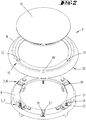
- the collision detection device 4 is arranged on the upper side of the device housing 2 adjacent to the distance measuring device 3 and consists of an annular first housing part 8 and an annular second housing part 9.
- the first housing part 8 is based on a vertical direction over the second housing part 9 and is also provided with a cover element 15 covered. Below the cover element 15 and centrally within or below the housing parts 8, 9, the distance measuring device 3 is arranged, or at least shock-sensitive component of the distance measuring device 3 such as a sensor, an optical deflecting device and the like.
- FIG. 2 shows the two housing parts 8, 9 and the lid member 15.
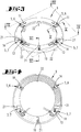
- the lower, second housing part 9 is shown in an enlarged view also in Figure 3. Shown is an orientation of the housing parts 8, 9, in which a leading forward in a forward movement of the surface processing device 1 front of the surface processing device 1 in the leaf level away from the viewer.
- the second housing part 9 has a collision detection device 4 with a total of four contact sensors 5, namely two vertical contact sensors 6 and two horizontal contact sensors 7.
- the two vertical contact sensors 6 are arranged relative to a conventional forward movement of the surface processing device 1 on the front side of the second housing part 9.
- the two horizontal contact sensors 7 are arranged on a rear part of the second housing part 9.
- the vertical contact sensors 6 are thus arranged in a leading partial area of the collision detection device 4, which would first come into contact with an obstacle during a normal forward movement of the surface treatment device 1.
- the vertical contact sensors 6 here each have a button 11, which protrudes over a direction of the first housing part 8 facing surface plane of the second housing part 9, ie in the vertical direction, and is movable relative to the second housing part 9.
- the probe 11 may be made of a deformable material, such as an elastomer, which deforms when applied vertically and downwards, that is, on the second housing part 9, moves.
- a spring element 14 under the button 11 is a spring element 14 (in FIG. 3 not shown), which in turn in operative connection with a switch 13 (also in FIG. 3 not shown).
- the two vertical contact sensors 6 are arranged at such a distance on the second housing part 9, that they substantially cover a detection range of about 180 ° of the ring shape of the housing parts 8, 9, namely the frontally arranged with respect to the direction of movement of the surface processing device 1 area.
- the two horizontal contact sensors 7 are arranged in a partial region of the second housing part 9, which is arranged on the rear side of the second housing part 9 relative to a conventional forward movement of the surface treatment device 1.
- the horizontal contact sensors 7 each have one in a recess 21 of the second housing part 9 embedded electronic switch 13 and a spring element 14 which is in operative connection with the switch 13.
- the horizontal contact sensor 7 is associated with a corresponding stop 12, which is formed on the first housing part 8 (see FIG. 2 ) and corresponding in shape in the recess 21 engages (in the assembled state of the two housing parts 8, 9).
- the stop 12 is connected via the spring element 14 with the switch 13 in operative connection.
- the stop 12 represents an actuating device 10 for the switch 13 and acts in a horizontal movement of the first housing part 8 against the switch 13th
- the second housing part 9 further has an additional recess 21, which is formed between the two horizontal contact sensors 7. Within the recess 21, a spring element 19 is arranged. In the mounted state of the first housing part 8 and the second housing part 9, a corresponding contact element 18 of the first housing part 8 engages in the recess 21, namely next to the spring element 19. The recess 21 and the contact element 18 together serve as a guide for the movement of the first housing part eighth relative to the second housing part 9. The movement is damped by the spring element 19.
- FIG. 2 illustrates the interaction between the first housing part 8 and the second housing part 9 in particular with respect to the formed on the first housing part 8 contact element 18 which is intended to engage in the corresponding recess 21 of the second housing part 9, and the stop 12 of the first housing part eighth which is intended for the shape-corresponding engagement in the recess 21 of the second housing part 9.
- the first housing part 8 on a lower side contact surface 20, which in the mounted state of the two housing parts 8, 9 slidably on the second housing part 9 and in particular on the buttons 11 is mounted. The sliding movement is guided by means of the contact element 18 and the corresponding recess 21.
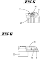
- FIG. 4 shows a cross section of the second housing part 9 along the line IV - IV of FIG. 3 , Recognizable here in addition to the Figures 2 and 3 the spring element 14 of the vertical contact sensor 6, which can be contracted in the vertical direction due to an actuation of the probe 11.
- FIG. 5 shows a cross section through a portion of the second housing part 9 along the line V - V in FIG. 3 ,
- the cross section is guided by a vertical contact sensor 6 and shows the probe 11, which protrudes beyond the surface plane of the housing part 9.
- the spring element 14 Under the button 11 is the spring element 14, which can be contracted down by an operation of the button 11 and acts under extension of the switching stroke on the arranged below the spring element 14 electronic switch 13, which then outputs a signal which with a vertical collision an obstacle is associated.
- FIG. 6 finally shows a cross section through a further portion of the second housing part 9 according to the line VI - VI in FIG. 3 ,
- the cross section is guided through the recess 21 with the spring element 19 arranged therein.
- an obstacle which has an impact force on the collision detection device 4 both in horizontal and in a vertical direction.
- an obstacle can be, for example, a wall-mounted, ground-level obstacle which touches the first housing part 8 of the collision detection device 4 above the detection plane of the distance measuring device 3.
- Such an obstacle can be, for example, a hanging part of an underside of a sofa which is located outside the detection plane of the distance measuring device 3 and hangs so low that the first housing part 8 and optionally the lid element 15 collides with it.
- the obstacle abuts, for example, on a region of the first housing part 8, which is located between the two vertical contact sensors 6. Since the first housing part 8 is mounted slidingly on the second housing part 9, the first housing part 8 is displaced relative to the second housing part 9, namely along the guide of the recess 21 of the second housing part 9 and the corresponding contact element 18 of the first housing part 8. At the same time the first housing part 8 is pressed down in the direction of the second housing part 9 due to the vertically acting force component of the impact, so that the abutment surface 20 of the first housing part 8 presses on the buttons 11 of the vertical contact sensors 6.
- a collision signal is triggered at the electronic switches 13 of the contact sensors 5, namely both at the vertical contact sensors 6 and at the horizontal contact sensors 7.
- the collision signal is further processed by an evaluation and control device of the surface treatment device 1 to determine which contact sensors 5 have detected a collision and in which position the obstacle is relative to the surface treatment device 1.
- the evaluation and control device here concludes that the obstacle is in front of and above the surface treatment device 1 in the direction of travel. Then a behavioral pattern is calculated which is suitable for guiding the surface treatment device 1 past the obstacle. For this purpose, a corresponding control command is subsequently generated, which drives the wheels 16 of the surface treatment device 1 such that the surface treatment device 1 executes a travel movement which leads around the obstacle.
Landscapes
- Engineering & Computer Science (AREA)
- Physics & Mathematics (AREA)
- Mechanical Engineering (AREA)
- General Physics & Mathematics (AREA)
- Aviation & Aerospace Engineering (AREA)
- Radar, Positioning & Navigation (AREA)
- Remote Sensing (AREA)
- Automation & Control Theory (AREA)
- Environmental Sciences (AREA)
- Life Sciences & Earth Sciences (AREA)
- Electromagnetism (AREA)
- Control Of Position, Course, Altitude, Or Attitude Of Moving Bodies (AREA)
- Manipulator (AREA)
- A Measuring Device Byusing Mechanical Method (AREA)
- Length Measuring Devices With Unspecified Measuring Means (AREA)
- Electric Suction Cleaners (AREA)
- Electric Vacuum Cleaner (AREA)
- Apparatus For Radiation Diagnosis (AREA)
Applications Claiming Priority (1)
| Application Number | Priority Date | Filing Date | Title |
|---|---|---|---|
| DE102016118650.3A DE102016118650A1 (de) | 2016-09-30 | 2016-09-30 | Sich selbsttätig fortbewegendes Flächenbearbeitungsgerät |
Publications (3)
| Publication Number | Publication Date |
|---|---|
| EP3300648A2 true EP3300648A2 (fr) | 2018-04-04 |
| EP3300648A3 EP3300648A3 (fr) | 2018-05-16 |
| EP3300648B1 EP3300648B1 (fr) | 2020-02-26 |
Family
ID=60019681
Family Applications (1)
| Application Number | Title | Priority Date | Filing Date |
|---|---|---|---|
| EP17192561.3A Active EP3300648B1 (fr) | 2016-09-30 | 2017-09-22 | Robot de nettoyage avec un dispositif de detection d'une collision |
Country Status (8)
| Country | Link |
|---|---|
| US (1) | US10514701B2 (fr) |
| EP (1) | EP3300648B1 (fr) |
| JP (1) | JP2018057846A (fr) |
| CN (1) | CN107874708B (fr) |
| DE (1) | DE102016118650A1 (fr) |
| ES (1) | ES2776652T3 (fr) |
| SG (1) | SG10201707759UA (fr) |
| TW (1) | TW201813572A (fr) |
Cited By (2)
| Publication number | Priority date | Publication date | Assignee | Title |
|---|---|---|---|---|
| CN110664329A (zh) * | 2019-10-18 | 2020-01-10 | 上海高仙自动化科技发展有限公司 | 碰撞传感器及清洁机器人 |
| US11147427B2 (en) * | 2019-01-15 | 2021-10-19 | Jason Yan | Fully floating contact redirecting device for cleaning robot |
Families Citing this family (36)
| Publication number | Priority date | Publication date | Assignee | Title |
|---|---|---|---|---|
| DE102016118650A1 (de) * | 2016-09-30 | 2018-04-05 | Vorwerk & Co. Interholding Gmbh | Sich selbsttätig fortbewegendes Flächenbearbeitungsgerät |
| CN206434287U (zh) * | 2016-10-20 | 2017-08-25 | 鸿富锦精密工业(深圳)有限公司 | 扫地机 |
| DE102016125358A1 (de) * | 2016-12-22 | 2018-06-28 | Vorwerk & Co. Interholding Gmbh | Verfahren zum Betrieb eines sich selbsttätig fortbewegenden Reinigungsgerätes sowie ein solches Reinigungsgerät |
| SE542024C2 (en) * | 2018-06-21 | 2020-02-11 | Husqvarna Ab | Robotic lawnmower with sensor for detecting relative movement between body parts of the lawnmower |
| CN108968846B (zh) * | 2018-08-15 | 2021-04-30 | 芜湖星途机器人科技有限公司 | 一种移动底盘防撞机构 |
| CN113163918B (zh) * | 2018-08-28 | 2023-03-28 | 灵动科技(北京)有限公司 | 具有库存承载台车的自动驾驶系统 |
| JP7151390B2 (ja) * | 2018-11-07 | 2022-10-12 | 三菱電機株式会社 | 自走式掃除機 |
| CN109388143B (zh) * | 2018-11-29 | 2024-03-12 | 天佑电器(苏州)有限公司 | 机器人及其行走控制方法 |
| CN111358390A (zh) * | 2018-12-26 | 2020-07-03 | 北京奇虎科技有限公司 | 回充装置、无人设备和充电座 |
| CN111358358A (zh) * | 2018-12-26 | 2020-07-03 | 北京奇虎科技有限公司 | 无人设备及其检测装置 |
| TWI688361B (zh) * | 2019-02-19 | 2020-03-21 | 廣達電腦股份有限公司 | 可拆解分離的機器人系統 |
| US11771290B2 (en) * | 2019-05-20 | 2023-10-03 | Irobot Corporation | Sensors for an autonomous cleaning robot |
| KR102791416B1 (ko) * | 2019-06-04 | 2025-04-08 | 삼성전자주식회사 | 로봇청소기 |
| CN110279348B (zh) * | 2019-06-18 | 2024-05-24 | 深圳瑞科时尚电子有限公司 | 一种自移动设备 |
| US11213181B2 (en) * | 2019-11-20 | 2022-01-04 | Irobot Corporation | Floating bumper in autonomous cleaning robot |
| TW202133784A (zh) * | 2020-01-20 | 2021-09-16 | 日商松下知識產權經營股份有限公司 | 自主行走型掃除機 |
| JP2021112416A (ja) * | 2020-01-20 | 2021-08-05 | パナソニックIpマネジメント株式会社 | 自律走行型掃除機 |
| JP7430540B2 (ja) * | 2020-02-03 | 2024-02-13 | 株式会社マキタ | 検出装置及びロボット集塵機 |
| DE102020132205A1 (de) * | 2020-12-03 | 2022-06-09 | Vorwerk & Co. Interholding Gesellschaft mit beschränkter Haftung | Sich selbsttätig fortbewegendes Bodenbearbeitungsgerät mit mindestens einem Absturzsensor |
| CN112704443A (zh) * | 2020-12-29 | 2021-04-27 | 深圳市银星智能科技股份有限公司 | 自主清洁设备 |
| USD989426S1 (en) * | 2021-01-20 | 2023-06-13 | Vorwerk & Co. Interholding Gmbh | Robot vacuum cleaner |
| JP7470901B2 (ja) * | 2021-02-19 | 2024-04-19 | パナソニックIpマネジメント株式会社 | 自律走行型掃除機 |
| US12296694B2 (en) | 2021-03-10 | 2025-05-13 | Techtronic Cordless Gp | Lawnmowers |
| CN113359759B (zh) * | 2021-06-24 | 2023-05-09 | 中国第一汽车股份有限公司 | 基于自动驾驶的泊车控制方法、系统、车辆及存储介质 |
| US12443180B2 (en) | 2021-11-10 | 2025-10-14 | Techtronic Cordless Gp | Robotic lawn mowers |
| CN116831477A (zh) * | 2022-01-11 | 2023-10-03 | 北京石头世纪科技股份有限公司 | 自动清洁设备 |
| AU2023200381A1 (en) | 2022-01-31 | 2023-08-17 | Techtronic Cordless Gp | Robotic garden tool |
| CN114868531B (zh) * | 2022-04-27 | 2023-04-25 | 深圳华芯信息技术股份有限公司 | 一种割草机及割草系统 |
| EP4270138A1 (fr) | 2022-04-28 | 2023-11-01 | Techtronic Cordless GP | Création d'une limite virtuelle pour un outil de jardin robotisé |
| CN115191870B (zh) * | 2022-05-13 | 2024-06-04 | 麦岩智能科技(北京)有限公司 | 一种碰撞检测传感装置 |
| US12472611B2 (en) | 2022-05-31 | 2025-11-18 | Techtronic Cordless Gp | Peg driver |
| US12490876B2 (en) * | 2022-06-29 | 2025-12-09 | Bissell Inc. | Robot with obstacle-detecting deformation sensors |
| EP4310621B1 (fr) | 2022-07-19 | 2025-02-12 | Techtronic Cordless GP | Dispositif d'affichage pour commander un outil robotique |
| AU2023206123A1 (en) | 2022-07-29 | 2024-02-15 | Techtronic Cordless Gp | Generation of a cryptography key for a robotic garden tool |
| WO2025201308A1 (fr) * | 2024-03-26 | 2025-10-02 | 北京石头世纪科技股份有限公司 | Dispositif et système de nettoyage |
| CN120360439B (zh) * | 2025-04-28 | 2025-10-31 | 广州创源机器人有限公司 | 一种偏心碰撞感应机构 |
Citations (1)
| Publication number | Priority date | Publication date | Assignee | Title |
|---|---|---|---|---|
| DE102013106294A1 (de) | 2013-06-18 | 2014-12-18 | Vorwerk & Co. Interholding Gmbh | Selbsttätig verfahrbares Gerät |
Family Cites Families (13)
| Publication number | Priority date | Publication date | Assignee | Title |
|---|---|---|---|---|
| US6941199B1 (en) * | 1998-07-20 | 2005-09-06 | The Procter & Gamble Company | Robotic system |
| DE10242257C5 (de) * | 2001-09-14 | 2017-05-11 | Vorwerk & Co. Interholding Gmbh | Selbsttätig verfahrbares Bodenstaub-Aufsammelgerät, sowie Kombination eines derartigen Aufsammelgerätes und einer Basisstation |
| NL1022340C1 (nl) * | 2003-01-09 | 2004-02-10 | Andreas Evert Cramer | Obstakel detectiesysteem voor automatisch vloer schoonmaak apparaat. |
| CN2810480Y (zh) * | 2004-12-15 | 2006-08-30 | 宁波富达电器有限公司 | 智能清扫机 |
| CN2827253Y (zh) * | 2005-09-14 | 2006-10-18 | 浙江大学 | 自动吸尘器的红外线视觉装置 |
| KR101361562B1 (ko) * | 2007-05-31 | 2014-02-13 | 삼성전자주식회사 | 청소로봇 |
| RU2486571C2 (ru) * | 2008-02-01 | 2013-06-27 | Конинклейке Филипс Электроникс Н.В. | Устройство, содержащее, по меньшей мере, тело и амортизатор, и робот-пылесос, содержащий такое устройство |
| KR101380269B1 (ko) * | 2008-08-22 | 2014-04-01 | 무라다기카이가부시끼가이샤 | 자율 이동 장치 |
| CN107024933B (zh) * | 2012-03-15 | 2021-07-06 | 艾罗伯特公司 | 包括传感器阵列的用于机器人的缓冲器 |
| US9282867B2 (en) * | 2012-12-28 | 2016-03-15 | Irobot Corporation | Autonomous coverage robot |
| TWI508692B (zh) * | 2013-02-08 | 2015-11-21 | Self-propelled trailing machine | |
| WO2015060672A1 (fr) * | 2013-10-25 | 2015-04-30 | 삼성전자주식회사 | Robot de nettoyage |
| DE102016118650A1 (de) * | 2016-09-30 | 2018-04-05 | Vorwerk & Co. Interholding Gmbh | Sich selbsttätig fortbewegendes Flächenbearbeitungsgerät |
-
2016
- 2016-09-30 DE DE102016118650.3A patent/DE102016118650A1/de not_active Withdrawn
-
2017
- 2017-09-12 TW TW106131251A patent/TW201813572A/zh unknown
- 2017-09-20 SG SG10201707759UA patent/SG10201707759UA/en unknown
- 2017-09-20 CN CN201710851276.4A patent/CN107874708B/zh active Active
- 2017-09-22 EP EP17192561.3A patent/EP3300648B1/fr active Active
- 2017-09-22 ES ES17192561T patent/ES2776652T3/es active Active
- 2017-09-25 JP JP2017183942A patent/JP2018057846A/ja not_active Withdrawn
- 2017-09-29 US US15/720,118 patent/US10514701B2/en active Active
Patent Citations (1)
| Publication number | Priority date | Publication date | Assignee | Title |
|---|---|---|---|---|
| DE102013106294A1 (de) | 2013-06-18 | 2014-12-18 | Vorwerk & Co. Interholding Gmbh | Selbsttätig verfahrbares Gerät |
Cited By (2)
| Publication number | Priority date | Publication date | Assignee | Title |
|---|---|---|---|---|
| US11147427B2 (en) * | 2019-01-15 | 2021-10-19 | Jason Yan | Fully floating contact redirecting device for cleaning robot |
| CN110664329A (zh) * | 2019-10-18 | 2020-01-10 | 上海高仙自动化科技发展有限公司 | 碰撞传感器及清洁机器人 |
Also Published As
| Publication number | Publication date |
|---|---|
| CN107874708B (zh) | 2021-06-22 |
| TW201813572A (zh) | 2018-04-16 |
| CN107874708A (zh) | 2018-04-06 |
| US20180095472A1 (en) | 2018-04-05 |
| US10514701B2 (en) | 2019-12-24 |
| ES2776652T3 (es) | 2020-07-31 |
| EP3300648A3 (fr) | 2018-05-16 |
| EP3300648B1 (fr) | 2020-02-26 |
| JP2018057846A (ja) | 2018-04-12 |
| SG10201707759UA (en) | 2018-04-27 |
| DE102016118650A1 (de) | 2018-04-05 |
Similar Documents
| Publication | Publication Date | Title |
|---|---|---|
| EP3300648B1 (fr) | Robot de nettoyage avec un dispositif de detection d'une collision | |
| EP1691656B1 (fr) | Aspirateur-traineau a deplacement automatique | |
| EP2710944B1 (fr) | Appareil de nettoyage du sol à déplacement automatique et procédé de fonctionnement d'un appareil de nettoyage du sol | |
| EP2764812B1 (fr) | Robot de nettoyage | |
| EP3351157B1 (fr) | Appareil de nettoyage se déplaçant automatiquement | |
| EP3351156A1 (fr) | Appareil de nettoyage se déplaçant automatiquement | |
| EP3139806B1 (fr) | Dispositif de nettoyage de sol roulant et manoeuvrant de manière autonome et méthode de nettoyage d'une surface de sol | |
| EP1973455B1 (fr) | Suceur pour aspirateur muni d'un moyen de delimitation a soulevement ou abaissement actif et procede correspondant | |
| DE102015109838A1 (de) | Saugdüse für einen Staubsauger | |
| DE102018200691A1 (de) | Bewegliches Haushaltsservicegerät, Verfahren zur Herstellung eines beweglichen Haushaltsservicegeräts | |
| EP0378528B1 (fr) | Procede pour guider un vehicule automoteur et vehicule automoteur | |
| DE102014106444B4 (de) | Verfahren zum Betrieb eines Saugroboters | |
| WO2019214769A1 (fr) | Dispositif et procédé pour sécuriser un appareil mobile à commande mécanique ou automatique et carreau de capteurs | |
| DE102006052017B4 (de) | Bearbeitungsmaschine | |
| DE202024107526U1 (de) | Reinigungsvorrichtung | |
| DE102013106294B4 (de) | Selbsttätig verfahrbares Gerät | |
| DE202017104980U1 (de) | Sich selbsttätig fortbewegendes Bodenbearbeitungsgerät | |
| DE4237578C2 (de) | Sicherheitsstoßfänger für ein automatisch gelenktes Fahrzeug | |
| DE102021202514B4 (de) | Mobiles, selbstfahrendes Gerät | |
| WO2022179698A1 (fr) | Procédé pour déterminer une distance minimale entre un objet et une surface d'appareil, dispositif de sécurité pour un appareil de manutention ayant une surface d'appareil, et appareil de manutention | |
| EP3239367A1 (fr) | Procédé de fonctionnement d'un brise-balles et brise-balles | |
| DE202021100125U1 (de) | Fahrzeug mit Sicherheitssensorik und Vorrichtung zur Durchführung eines Sicherheitsverfahrens | |
| EP4008229B1 (fr) | Appareil de traitement du sol autonome pourvu d'une pluralité de capteurs de chute | |
| DE102008009615B4 (de) | Selbsttätig verfahrbares Bodenstaub-Aufsammelgerät sowie Sensoranordnung | |
| WO2020173673A1 (fr) | Véhicule autonome comportant un dispositif capteur |
Legal Events
| Date | Code | Title | Description |
|---|---|---|---|
| PUAI | Public reference made under article 153(3) epc to a published international application that has entered the european phase |
Free format text: ORIGINAL CODE: 0009012 |
|
| STAA | Information on the status of an ep patent application or granted ep patent |
Free format text: STATUS: THE APPLICATION HAS BEEN PUBLISHED |
|
| AK | Designated contracting states |
Kind code of ref document: A2 Designated state(s): AL AT BE BG CH CY CZ DE DK EE ES FI FR GB GR HR HU IE IS IT LI LT LU LV MC MK MT NL NO PL PT RO RS SE SI SK SM TR |
|
| AX | Request for extension of the european patent |
Extension state: BA ME |
|
| PUAL | Search report despatched |
Free format text: ORIGINAL CODE: 0009013 |
|
| AK | Designated contracting states |
Kind code of ref document: A3 Designated state(s): AL AT BE BG CH CY CZ DE DK EE ES FI FR GB GR HR HU IE IS IT LI LT LU LV MC MK MT NL NO PL PT RO RS SE SI SK SM TR |
|
| AX | Request for extension of the european patent |
Extension state: BA ME |
|
| RIC1 | Information provided on ipc code assigned before grant |
Ipc: A01D 34/00 20060101ALI20180409BHEP Ipc: A47L 9/28 20060101AFI20180409BHEP |
|
| STAA | Information on the status of an ep patent application or granted ep patent |
Free format text: STATUS: REQUEST FOR EXAMINATION WAS MADE |
|
| 17P | Request for examination filed |
Effective date: 20180706 |
|
| RBV | Designated contracting states (corrected) |
Designated state(s): AL AT BE BG CH CY CZ DE DK EE ES FI FR GB GR HR HU IE IS IT LI LT LU LV MC MK MT NL NO PL PT RO RS SE SI SK SM TR |
|
| RIC1 | Information provided on ipc code assigned before grant |
Ipc: A47L 9/28 20060101AFI20190621BHEP Ipc: A01D 34/00 20060101ALI20190621BHEP |
|
| GRAP | Despatch of communication of intention to grant a patent |
Free format text: ORIGINAL CODE: EPIDOSNIGR1 |
|
| STAA | Information on the status of an ep patent application or granted ep patent |
Free format text: STATUS: GRANT OF PATENT IS INTENDED |
|
| INTG | Intention to grant announced |
Effective date: 20190918 |
|
| GRAS | Grant fee paid |
Free format text: ORIGINAL CODE: EPIDOSNIGR3 |
|
| GRAA | (expected) grant |
Free format text: ORIGINAL CODE: 0009210 |
|
| STAA | Information on the status of an ep patent application or granted ep patent |
Free format text: STATUS: THE PATENT HAS BEEN GRANTED |
|
| AK | Designated contracting states |
Kind code of ref document: B1 Designated state(s): AL AT BE BG CH CY CZ DE DK EE ES FI FR GB GR HR HU IE IS IT LI LT LU LV MC MK MT NL NO PL PT RO RS SE SI SK SM TR |
|
| REG | Reference to a national code |
Ref country code: GB Ref legal event code: FG4D Free format text: NOT ENGLISH |
|
| REG | Reference to a national code |
Ref country code: CH Ref legal event code: EP |
|
| REG | Reference to a national code |
Ref country code: AT Ref legal event code: REF Ref document number: 1236626 Country of ref document: AT Kind code of ref document: T Effective date: 20200315 |
|
| REG | Reference to a national code |
Ref country code: IE Ref legal event code: FG4D Free format text: LANGUAGE OF EP DOCUMENT: GERMAN |
|
| REG | Reference to a national code |
Ref country code: DE Ref legal event code: R096 Ref document number: 502017003949 Country of ref document: DE |
|
| PG25 | Lapsed in a contracting state [announced via postgrant information from national office to epo] |
Ref country code: RS Free format text: LAPSE BECAUSE OF FAILURE TO SUBMIT A TRANSLATION OF THE DESCRIPTION OR TO PAY THE FEE WITHIN THE PRESCRIBED TIME-LIMIT Effective date: 20200226 Ref country code: NO Free format text: LAPSE BECAUSE OF FAILURE TO SUBMIT A TRANSLATION OF THE DESCRIPTION OR TO PAY THE FEE WITHIN THE PRESCRIBED TIME-LIMIT Effective date: 20200526 Ref country code: FI Free format text: LAPSE BECAUSE OF FAILURE TO SUBMIT A TRANSLATION OF THE DESCRIPTION OR TO PAY THE FEE WITHIN THE PRESCRIBED TIME-LIMIT Effective date: 20200226 |
|
| REG | Reference to a national code |
Ref country code: ES Ref legal event code: FG2A Ref document number: 2776652 Country of ref document: ES Kind code of ref document: T3 Effective date: 20200731 Ref country code: NL Ref legal event code: MP Effective date: 20200226 |
|
| REG | Reference to a national code |
Ref country code: LT Ref legal event code: MG4D |
|
| PG25 | Lapsed in a contracting state [announced via postgrant information from national office to epo] |
Ref country code: LV Free format text: LAPSE BECAUSE OF FAILURE TO SUBMIT A TRANSLATION OF THE DESCRIPTION OR TO PAY THE FEE WITHIN THE PRESCRIBED TIME-LIMIT Effective date: 20200226 Ref country code: SE Free format text: LAPSE BECAUSE OF FAILURE TO SUBMIT A TRANSLATION OF THE DESCRIPTION OR TO PAY THE FEE WITHIN THE PRESCRIBED TIME-LIMIT Effective date: 20200226 Ref country code: BG Free format text: LAPSE BECAUSE OF FAILURE TO SUBMIT A TRANSLATION OF THE DESCRIPTION OR TO PAY THE FEE WITHIN THE PRESCRIBED TIME-LIMIT Effective date: 20200526 Ref country code: IS Free format text: LAPSE BECAUSE OF FAILURE TO SUBMIT A TRANSLATION OF THE DESCRIPTION OR TO PAY THE FEE WITHIN THE PRESCRIBED TIME-LIMIT Effective date: 20200626 Ref country code: GR Free format text: LAPSE BECAUSE OF FAILURE TO SUBMIT A TRANSLATION OF THE DESCRIPTION OR TO PAY THE FEE WITHIN THE PRESCRIBED TIME-LIMIT Effective date: 20200527 Ref country code: HR Free format text: LAPSE BECAUSE OF FAILURE TO SUBMIT A TRANSLATION OF THE DESCRIPTION OR TO PAY THE FEE WITHIN THE PRESCRIBED TIME-LIMIT Effective date: 20200226 |
|
| PG25 | Lapsed in a contracting state [announced via postgrant information from national office to epo] |
Ref country code: NL Free format text: LAPSE BECAUSE OF FAILURE TO SUBMIT A TRANSLATION OF THE DESCRIPTION OR TO PAY THE FEE WITHIN THE PRESCRIBED TIME-LIMIT Effective date: 20200226 |
|
| PG25 | Lapsed in a contracting state [announced via postgrant information from national office to epo] |
Ref country code: LT Free format text: LAPSE BECAUSE OF FAILURE TO SUBMIT A TRANSLATION OF THE DESCRIPTION OR TO PAY THE FEE WITHIN THE PRESCRIBED TIME-LIMIT Effective date: 20200226 Ref country code: DK Free format text: LAPSE BECAUSE OF FAILURE TO SUBMIT A TRANSLATION OF THE DESCRIPTION OR TO PAY THE FEE WITHIN THE PRESCRIBED TIME-LIMIT Effective date: 20200226 Ref country code: SK Free format text: LAPSE BECAUSE OF FAILURE TO SUBMIT A TRANSLATION OF THE DESCRIPTION OR TO PAY THE FEE WITHIN THE PRESCRIBED TIME-LIMIT Effective date: 20200226 Ref country code: PT Free format text: LAPSE BECAUSE OF FAILURE TO SUBMIT A TRANSLATION OF THE DESCRIPTION OR TO PAY THE FEE WITHIN THE PRESCRIBED TIME-LIMIT Effective date: 20200719 Ref country code: RO Free format text: LAPSE BECAUSE OF FAILURE TO SUBMIT A TRANSLATION OF THE DESCRIPTION OR TO PAY THE FEE WITHIN THE PRESCRIBED TIME-LIMIT Effective date: 20200226 Ref country code: SM Free format text: LAPSE BECAUSE OF FAILURE TO SUBMIT A TRANSLATION OF THE DESCRIPTION OR TO PAY THE FEE WITHIN THE PRESCRIBED TIME-LIMIT Effective date: 20200226 Ref country code: EE Free format text: LAPSE BECAUSE OF FAILURE TO SUBMIT A TRANSLATION OF THE DESCRIPTION OR TO PAY THE FEE WITHIN THE PRESCRIBED TIME-LIMIT Effective date: 20200226 |
|
| PGFP | Annual fee paid to national office [announced via postgrant information from national office to epo] |
Ref country code: CZ Payment date: 20200911 Year of fee payment: 4 |
|
| REG | Reference to a national code |
Ref country code: DE Ref legal event code: R097 Ref document number: 502017003949 Country of ref document: DE |
|
| PLBE | No opposition filed within time limit |
Free format text: ORIGINAL CODE: 0009261 |
|
| STAA | Information on the status of an ep patent application or granted ep patent |
Free format text: STATUS: NO OPPOSITION FILED WITHIN TIME LIMIT |
|
| 26N | No opposition filed |
Effective date: 20201127 |
|
| PG25 | Lapsed in a contracting state [announced via postgrant information from national office to epo] |
Ref country code: SI Free format text: LAPSE BECAUSE OF FAILURE TO SUBMIT A TRANSLATION OF THE DESCRIPTION OR TO PAY THE FEE WITHIN THE PRESCRIBED TIME-LIMIT Effective date: 20200226 Ref country code: PL Free format text: LAPSE BECAUSE OF FAILURE TO SUBMIT A TRANSLATION OF THE DESCRIPTION OR TO PAY THE FEE WITHIN THE PRESCRIBED TIME-LIMIT Effective date: 20200226 |
|
| REG | Reference to a national code |
Ref country code: CH Ref legal event code: PL |
|
| REG | Reference to a national code |
Ref country code: BE Ref legal event code: MM Effective date: 20200930 |
|
| PG25 | Lapsed in a contracting state [announced via postgrant information from national office to epo] |
Ref country code: LU Free format text: LAPSE BECAUSE OF NON-PAYMENT OF DUE FEES Effective date: 20200922 |
|
| PG25 | Lapsed in a contracting state [announced via postgrant information from national office to epo] |
Ref country code: IE Free format text: LAPSE BECAUSE OF NON-PAYMENT OF DUE FEES Effective date: 20200922 Ref country code: LI Free format text: LAPSE BECAUSE OF NON-PAYMENT OF DUE FEES Effective date: 20200930 Ref country code: CH Free format text: LAPSE BECAUSE OF NON-PAYMENT OF DUE FEES Effective date: 20200930 Ref country code: BE Free format text: LAPSE BECAUSE OF NON-PAYMENT OF DUE FEES Effective date: 20200930 |
|
| GBPC | Gb: european patent ceased through non-payment of renewal fee |
Effective date: 20210922 |
|
| PG25 | Lapsed in a contracting state [announced via postgrant information from national office to epo] |
Ref country code: TR Free format text: LAPSE BECAUSE OF FAILURE TO SUBMIT A TRANSLATION OF THE DESCRIPTION OR TO PAY THE FEE WITHIN THE PRESCRIBED TIME-LIMIT Effective date: 20200226 Ref country code: MT Free format text: LAPSE BECAUSE OF FAILURE TO SUBMIT A TRANSLATION OF THE DESCRIPTION OR TO PAY THE FEE WITHIN THE PRESCRIBED TIME-LIMIT Effective date: 20200226 Ref country code: CZ Free format text: LAPSE BECAUSE OF NON-PAYMENT OF DUE FEES Effective date: 20210922 Ref country code: CY Free format text: LAPSE BECAUSE OF FAILURE TO SUBMIT A TRANSLATION OF THE DESCRIPTION OR TO PAY THE FEE WITHIN THE PRESCRIBED TIME-LIMIT Effective date: 20200226 |
|
| PG25 | Lapsed in a contracting state [announced via postgrant information from national office to epo] |
Ref country code: MK Free format text: LAPSE BECAUSE OF FAILURE TO SUBMIT A TRANSLATION OF THE DESCRIPTION OR TO PAY THE FEE WITHIN THE PRESCRIBED TIME-LIMIT Effective date: 20200226 Ref country code: MC Free format text: LAPSE BECAUSE OF FAILURE TO SUBMIT A TRANSLATION OF THE DESCRIPTION OR TO PAY THE FEE WITHIN THE PRESCRIBED TIME-LIMIT Effective date: 20200226 Ref country code: AL Free format text: LAPSE BECAUSE OF FAILURE TO SUBMIT A TRANSLATION OF THE DESCRIPTION OR TO PAY THE FEE WITHIN THE PRESCRIBED TIME-LIMIT Effective date: 20200226 |
|
| PG25 | Lapsed in a contracting state [announced via postgrant information from national office to epo] |
Ref country code: GB Free format text: LAPSE BECAUSE OF NON-PAYMENT OF DUE FEES Effective date: 20210922 |
|
| P01 | Opt-out of the competence of the unified patent court (upc) registered |
Effective date: 20230517 |
|
| REG | Reference to a national code |
Ref country code: AT Ref legal event code: MM01 Ref document number: 1236626 Country of ref document: AT Kind code of ref document: T Effective date: 20220922 |
|
| PG25 | Lapsed in a contracting state [announced via postgrant information from national office to epo] |
Ref country code: AT Free format text: LAPSE BECAUSE OF NON-PAYMENT OF DUE FEES Effective date: 20220922 |
|
| PGFP | Annual fee paid to national office [announced via postgrant information from national office to epo] |
Ref country code: DE Payment date: 20250919 Year of fee payment: 9 |
|
| PGFP | Annual fee paid to national office [announced via postgrant information from national office to epo] |
Ref country code: FR Payment date: 20250925 Year of fee payment: 9 |
|
| PGFP | Annual fee paid to national office [announced via postgrant information from national office to epo] |
Ref country code: IT Payment date: 20250930 Year of fee payment: 9 |
|
| PGFP | Annual fee paid to national office [announced via postgrant information from national office to epo] |
Ref country code: ES Payment date: 20251020 Year of fee payment: 9 |