EP3300675B1 - Composants pour un instrument médical et instrument médical - Google Patents
Composants pour un instrument médical et instrument médical Download PDFInfo
- Publication number
- EP3300675B1 EP3300675B1 EP17192042.4A EP17192042A EP3300675B1 EP 3300675 B1 EP3300675 B1 EP 3300675B1 EP 17192042 A EP17192042 A EP 17192042A EP 3300675 B1 EP3300675 B1 EP 3300675B1
- Authority
- EP
- European Patent Office
- Prior art keywords
- transmission device
- component
- shaft
- abutment surface
- proximal end
- Prior art date
- Legal status (The legal status is an assumption and is not a legal conclusion. Google has not performed a legal analysis and makes no representation as to the accuracy of the status listed.)
- Active
Links
Images



Classifications
-
- A—HUMAN NECESSITIES
- A61—MEDICAL OR VETERINARY SCIENCE; HYGIENE
- A61B—DIAGNOSIS; SURGERY; IDENTIFICATION
- A61B90/00—Instruments, implements or accessories specially adapted for surgery or diagnosis and not covered by any of the groups A61B1/00 - A61B50/00, e.g. for luxation treatment or for protecting wound edges
- A61B90/03—Automatic limiting or abutting means, e.g. for safety
-
- A—HUMAN NECESSITIES
- A61—MEDICAL OR VETERINARY SCIENCE; HYGIENE
- A61B—DIAGNOSIS; SURGERY; IDENTIFICATION
- A61B17/00—Surgical instruments, devices or methods
- A61B17/28—Surgical forceps
- A61B17/29—Forceps for use in minimally invasive surgery
-
- A—HUMAN NECESSITIES
- A61—MEDICAL OR VETERINARY SCIENCE; HYGIENE
- A61B—DIAGNOSIS; SURGERY; IDENTIFICATION
- A61B17/00—Surgical instruments, devices or methods
- A61B17/00234—Surgical instruments, devices or methods for minimally invasive surgery
- A61B2017/00292—Surgical instruments, devices or methods for minimally invasive surgery mounted on or guided by flexible, e.g. catheter-like, means
- A61B2017/0034—Surgical instruments, devices or methods for minimally invasive surgery mounted on or guided by flexible, e.g. catheter-like, means adapted to be inserted through a working channel of an endoscope
-
- A—HUMAN NECESSITIES
- A61—MEDICAL OR VETERINARY SCIENCE; HYGIENE
- A61B—DIAGNOSIS; SURGERY; IDENTIFICATION
- A61B17/00—Surgical instruments, devices or methods
- A61B2017/0046—Surgical instruments, devices or methods with a releasable handle; with handle and operating part separable
-
- A—HUMAN NECESSITIES
- A61—MEDICAL OR VETERINARY SCIENCE; HYGIENE
- A61B—DIAGNOSIS; SURGERY; IDENTIFICATION
- A61B17/00—Surgical instruments, devices or methods
- A61B2017/00526—Methods of manufacturing
-
- A—HUMAN NECESSITIES
- A61—MEDICAL OR VETERINARY SCIENCE; HYGIENE
- A61B—DIAGNOSIS; SURGERY; IDENTIFICATION
- A61B17/00—Surgical instruments, devices or methods
- A61B17/28—Surgical forceps
- A61B17/29—Forceps for use in minimally invasive surgery
- A61B2017/2901—Details of shaft
- A61B2017/2902—Details of shaft characterized by features of the actuating rod
-
- A—HUMAN NECESSITIES
- A61—MEDICAL OR VETERINARY SCIENCE; HYGIENE
- A61B—DIAGNOSIS; SURGERY; IDENTIFICATION
- A61B17/00—Surgical instruments, devices or methods
- A61B17/28—Surgical forceps
- A61B17/29—Forceps for use in minimally invasive surgery
- A61B2017/2901—Details of shaft
- A61B2017/2905—Details of shaft flexible
-
- A—HUMAN NECESSITIES
- A61—MEDICAL OR VETERINARY SCIENCE; HYGIENE
- A61B—DIAGNOSIS; SURGERY; IDENTIFICATION
- A61B90/00—Instruments, implements or accessories specially adapted for surgery or diagnosis and not covered by any of the groups A61B1/00 - A61B50/00, e.g. for luxation treatment or for protecting wound edges
- A61B90/03—Automatic limiting or abutting means, e.g. for safety
- A61B2090/033—Abutting means, stops, e.g. abutting on tissue or skin
- A61B2090/034—Abutting means, stops, e.g. abutting on tissue or skin abutting on parts of the device itself
-
- A—HUMAN NECESSITIES
- A61—MEDICAL OR VETERINARY SCIENCE; HYGIENE
- A61B—DIAGNOSIS; SURGERY; IDENTIFICATION
- A61B2217/00—General characteristics of surgical instruments
- A61B2217/002—Auxiliary appliance
- A61B2217/007—Auxiliary appliance with irrigation system
-
- A—HUMAN NECESSITIES
- A61—MEDICAL OR VETERINARY SCIENCE; HYGIENE
- A61B—DIAGNOSIS; SURGERY; IDENTIFICATION
- A61B34/00—Computer-aided surgery; Manipulators or robots specially adapted for use in surgery
- A61B34/70—Manipulators specially adapted for use in surgery
Definitions
- the present invention relates to a component for a medical instrument and to a medical instrument.
- the present invention relates in particular to measures which, under certain circumstances, can prevent a medical instrument from being destroyed by improper use or handling.
- a surgical instrument 10 is described with a device 30 for limiting the force transmission (column 7, lines 39 to 41).
- This device 30 connects a first section 32 and a second section 54 of an otherwise rod-shaped actuating element 26 ( Figures 1, 2 ).
- the device 30 comprises an approximately hollow-cylindrical housing 38 which is connected to the first section 32 of the rod-shaped actuating element 26 is rigidly connected and has axially extending grooves (column 7, lines 45 to 55) and an inner cone (column 8, lines 14 to 16; Figure 4 ).
- the device 30 further comprises a cone 56 which is connected to the second section 54 of the rod-shaped actuating element 26, has a conical wedge surface 57 and is arranged in the hollow-cylindrical housing 38 such that the cone 56 rests against the inner cone 64 (column 8, lines 7 to 23). If a predetermined force is exceeded, the hollow-cylindrical housing 38 is deformed and the cone 56 is partially pulled out of it (column 8, lines 33 to 53).
- EP 2 510 889 A1 a handling device for a microinvasive surgical instrument is described.
- a pre-tensioned compression spring 564 in a cup-shaped component 562 limits a tensile force to be transmitted from a rod 561 to a transmission rod 40 (paragraph [0083] of EP 2 510 888 A1 ; Figure 3 ).
- a surgical instrument 10 with a device 30 for limiting the force transmission is described (column 7, lines 39 to 41, figures).
- This device 30 connects a first, distal section 32 and a second, proximal section 54 of an otherwise rod-shaped actuating element 26 (column 7, lines 45 to 47; column 8, lines 7 to 8; Figures 1, 2 ).
- the device 30 comprises a housing 38, which is approximately hollow-cylindrical in shape and which is rigidly connected to the first section 32 of the rod-shaped actuating element 26 and has axially extending Grooves (column 7, lines 45 to 55) and an inner cone 64 (column 8, lines 14 to 16; Figure 4 ).
- the device 30 further comprises a cone 56 which is connected to the second section 54 of the rod-shaped actuating element 26, has a conical wedge surface 57 and is arranged in the housing 38 such that the cone 56 rests against the inner cone 64 (column 8, lines 7 to 23). If a predetermined force is exceeded, the housing 38 is deformed and the cone 56 is partially pulled out of it (column 8, lines 33 to 53).
- EP 2 561 816 A1 A tool for a microinvasive surgical instrument is described.
- EP 2 269 522 A1 a medical instrument 1 is described in which a force limiting device 8 is provided in the handle 3, which reversibly separates two coupled components when a limit load is exceeded (paragraph [0024]).
- a gripping forceps 1 with an insertion area 2 that can be inserted into a body cavity of a patient is described (column 4, lines 14 to 22, Figure 1 ).
- an actuating shaft 10 is arranged, which connects gripping parts 27a, 27b in a tweezer area 3 with an operating area 4 (column 4, lines 31 to 50 and lines 66 to 68, Figures 3, 4 ).
- the proximal end of the transmission shaft 10 is formed by a coupling rod 41 (column 5, lines 46 to 56, Figure 4 ).
- a step between a large diameter portion 41a of the coupling rod 41 and a small diameter portion 41b of the coupling rod 41 and a step between a rod holding hole 37 and a through hole 38 in the operating portion 4 form a stopper device 12 which restricts the proximal movement of the actuating shaft 10 (column 6, lines 19 to 28, Figure 4 ).
- An object of the present invention is to provide an improved component for a medical instrument, an improved medical instrument and an improved method for producing a component for a medical instrument.
- a component for a medical instrument comprises a shaft, a transmission device which is movable in the shaft for transmitting a force from a handling device coupled to the proximal end of the component to a tool at the distal end of the component, a stop surface on the shaft and a stop surface on the transmission device, wherein the stop surface of the shaft and the stop surface of the transmission device are arranged such that mechanical contact between the stop surface and the transmission device and the stop surface of the shaft limits a movement of the transmission device relative to the shaft in a proximally direction.
- the component is provided and designed to be mechanically connected and/or coupled to one or more other components in such a way that a medical instrument is formed.
- the component is in particular a component for a microinvasive medical instrument, wherein the shaft has a diameter of a few millimeters or less and a length of a few centimeters or a few or a few decimetres.
- the shaft can, for example, be provided and designed to be introduced into a working channel of an endoscope.
- the proximal end of the shaft is provided and designed in particular for a non-destructively detachable or permanent or non-destructively detachable mechanical connection to a handling device.
- the proximal end of the transmission device is provided and designed in particular for a non-destructively detachable or permanent or non-destructively detachable mechanical coupling to a manually movable part of a handling device.
- the component can have a tool at its distal end, which is in particular rigidly connected to the distal end of the shaft, and which has a movable part (for example a pivotable branch or a pivotable jaw part).
- the movable part of the tool is mechanically coupled directly or indirectly to the distal end of the transmission device in such a way that a movement of the transmission device relative to the shaft is associated with a movement of the movable part of the tool relative to another part of the tool.
- the tool can be mechanically connected and coupled to the distal end of the shaft and to the distal end of the transmission device in a non-destructively detachable or permanent or non-non-destructively detachable manner.
- the component may not have a tool, but may be provided and designed for the non-destructively detachable or permanent or non-destructively detachable mechanical connection and coupling of a tool to the distal end of the shaft and to the distal end of the transmission device.
- the transmission device is movable relative to the shaft in particular in a direction parallel to the longitudinal axis of the shaft.
- the transmission device is provided and designed in particular to transmit a tensile force from a movable part of a handling device coupled to the proximal end of the transmission device to a movable part of a tool coupled to the distal end of the transmission device.
- the transmission device can be provided and designed to transmit a thrust force from a movable part of a handling device coupled to the proximal end of the transmission device to a movable part of a tool coupled to the distal end of the transmission device.
- the distal end of the transmission device can be coupled or is coupled in particular to a movable part of a tool in such a way that a proximal movement of the transmission device is accompanied by the intended active movement of the movable part of the tool.
- the force required for the active movement of the movable part of the tool is transmitted by a tensile force or tensile stress in the transmission device.
- the active movement of the movable part of a tool is the movement in which the tool develops the intended effect. In the case of pliers or another tool for gripping, holding, squeezing, punching or cutting, this is usually the closing movement in which two (in some cases more) jaw parts or branches are moved towards each other. In other cases, the active movement can be a movement in which jaw parts or branches be moved away from each other, for example in a tool for spreading or expanding a vessel or other hollow space.
- the stop surface of the shaft and the stop surface of the transmission device can be arranged such that a mechanical contact between the stop surface of the transmission device and the stop surface of the shaft limits a movement of the transmission device relative to the shaft in the distal direction.
- the stop surface of the shaft is oriented distally and the stop surface of the transmission device is oriented proximally.
- the movement of the distal end of the transmission device relative to the distal end of the shaft is limited proximally and the stop surface of the shaft and the stop surface of the transmission device are arranged such that mechanical contact between the stop surface of the transmission device and the stop surface of the shaft limits an elastic deformation of the transmission device by a force transmitted by the transmission device to a predetermined maximum value, wherein the predetermined maximum value of the elastic deformation and elastic properties of the transmission device are selected such that, at the force which is present at the predetermined maximum value of the elastic deformation of the transmission device, destruction or damage to the shaft, the transmission device and a tool connected to the distal end of the shaft and coupled to the distal end of the transmission device is excluded.
- the movement of the distal end of the transmission device relative to the distal end of the shaft is in particular by a tool which is connected to the distal end of the shaft mechanically connected and mechanically coupled to the distal end of the transmission device.
- the component does not comprise a tool at the distal end, but is intended and designed for mechanical connection and coupling to a tool
- the movement of the distal end of the transmission device relative to the distal end of the shaft is in particular only limited proximally or only limited in the manner required for the limitation of the transmitted force to the predetermined maximum value described here if the distal end of the shaft is connected to the tool provided for the component or to one of several tools provided for the component in the intended manner and one or more movable parts of the tool are mechanically coupled to the distal end of the transmission device in the intended manner.
- the stop surface of the shaft and the stop surface of the transmission device are in particular arranged such that a mechanical contact between the stop surface of the transmission device and the stop surface of the shaft during the intended use limits an elastic deformation of the transmission device by a force transmitted by the transmission device to a predetermined maximum value, wherein the predetermined maximum value of the elastic deformation and elastic properties of the transmission device are selected such that, with the force present at the predetermined maximum value of the elastic deformation of the transmission device, destruction or damage to the shaft, the transmission device and a tool connected to the distal end of the shaft and coupled to the distal end of the transmission device is excluded.
- Plastic deformation of the transmission device, the shaft or a tool coupled to the distal end of the shaft and the distal end of the transmission device is also a damage to the transmission device, the shaft or the tool. Excluding destruction or damage to the shaft, the transmission device and a tool coupled to the distal end of the shaft and the distal end of the transmission device therefore also means that the transmission device, the shaft and the tool are only elastically and not plastically deformed.
- a tool for cutting, gripping, holding, squeezing or punching that is connected to the distal end of the shaft and coupled to the distal end of the transmission device can be blocked in its fully open configuration, for example by a hard object or an object that does not yield under the force that can be generated. If the transmission device is coupled to the movable part of the tool in such a way that a tensile force to be transmitted by the transmission device is required to close the tool, the transmission device is maximally deformed, namely stretched, when the tool is blocked in the fully open state and the stop surface of the transmission device rests against the stop surface of the shaft.
- the stop surface of the transmission device and the stop surface of the shaft are positioned and the elastic properties of the transmission device are selected so that even in this case the shaft, the transmission device and a tool coupled to the distal end of the shaft are not damaged or destroyed.
- the stop surface of the shaft is arranged near the proximal end of the shaft and the stop surface of the transmission device is arranged near the proximal end of the transmission device.
- the distance between the stop surface of the shaft and the proximal end of the shaft is in particular no more than one fifth or no more than one tenth of the length of the shaft.
- the distance between the stop surface of the transmission device and the proximal end of the transmission device is in particular no more than one fifth or no more than one tenth of the length of the transmission device.
- the stop surface of the shaft and the stop surface of the transmission device are arranged in particular in a proximal region of the shaft in which the shaft has an enlarged diameter or an enlarged cross-section.
- the stop surface of the shaft and the stop surface of the transmission device are arranged in particular in a region of the shaft which is intended for reception in a handling device.
- the shaft has a long and thin tubular section and a proximal section that is significantly thicker than the tubular section.
- the long and thin tubular section of the shaft generally extends over at least two thirds or at least four fifths or at least nine tenths of the length of the shaft and has a diameter of a few millimeters or less.
- the diameter and cross section of the proximal section of the shaft are generally significantly larger than the diameter and cross section of the long and thin tubular section. In the proximal section, more installation space is available for the stop surface of the shaft and for the stop surface of the transmission device.
- the transmission device has its minimum cross-sectional area in particular in a section distal to the stop surface of the transmission device, wherein all cross-sectional areas of the transmission device proximal to the stop surface of the transmission device are larger than the minimum cross-sectional area of the transmission device.
- the cross-sectional area of the transmission device is, in particular, substantially larger proximal to the stop surface of the transmission device than distal to the stop surface of the transmission device.
- the cross-sectional area of the transmission device is, for example, substantially larger proximal to the stop surface of the transmission device than distal to the stop surface of the transmission device by at least a factor of 5 or at least a factor of 10 or at least a factor of 20.
- the transmission device has, in particular, distal to the stop surface of the Transmission device has a largely constant circular cross-section with a diameter of less than 1 mm.
- the transmission device in particular has a continuous circular or other cross-section with a cross-sectional area of several square millimeters.
- a design of the transmission device such that its cross-sectional area proximal to the stop surface of the transmission device is significantly larger than distally enables a high robustness of the transmission device proximal to the stop surface of the transmission device and therefore a low risk of destruction or damage due to excessive force.
- the transmission device has its minimum tensile strength in particular in a section distal to the stop surface of the transmission device, wherein the tensile strength of the transmission device proximal to the stop surface of the transmission device is consistently greater than the minimum tensile strength of the transmission device.
- the tensile strength of the transmission device is, in particular, significantly greater than the minimum tensile strength of the transmission device proximal to the stop surface of the transmission device.
- the tensile strength of the transmission device is, for example, at least a factor of 5 or a factor of 10 or a factor of 20 greater than the minimum tensile strength of the transmission device proximal to the stop surface of the transmission device.
- the transmission device is elastically deformable up to a first maximum force, in particular distal to the stop surface of the transmission device, wherein the transmission device is elastically deformable up to a second maximum force proximal to the stop surface of the transmission device, and wherein the second maximum force is greater than the first maximum force.
- the maximum force up to which the transmission device is elastically deformable at a certain point is the greatest force at which the transmission device is not yet plastically deformed at the certain point.
- the second maximum force is in particular significantly greater than the first maximum force.
- the second maximum force is in particular at least a factor of 2 or at least a factor of 5 or at least a factor of 10 or at least a factor of 20 or at least a factor of 50 greater than the first maximum force.
- a significantly greater mechanical robustness of the transmission device proximal to the stop surface of the transmission device can also significantly reduce the risk of destruction or damage to the transmission device proximal to the stop surface of the transmission device.
- the transmission device cannot be removed from the shaft either proximally or distally without disassembling the shaft.
- a component as described here further comprises, in particular, a further stop surface on the shaft and a further stop surface on the transmission device, wherein the further stop surface of the shaft and the further stop surface of the transmission device are arranged such that a mechanical contact between the further stop surface of the transmission device and the further stop surface of the shaft limits a movement of the transmission device relative to the shaft in the distal direction.
- the further stop surface of the shaft is arranged in particular near the proximal end of the shaft and in particular near the stop surface of the shaft.
- the further stop surface of the transmission device is in particular near the proximal end the transmission device and in particular close to the stop surface of the transmission device.
- the further stop surface of the shaft is oriented proximally and the further stop surface of the transmission device is oriented distally.
- Limiting the movement of the transmission device relative to the shaft in the distal direction can prevent overloading, damage or destruction of the transmission device, the shaft or a tool at the distal end of the component due to excessive thrust transmitted by the transmission device.
- compression of the transmission device distal to the further stop surface of the transmission device can be prevented.
- the transmission device in particular has an outwardly projecting collar, wherein the shaft has a groove which widens a channel in which the transmission device is arranged, wherein the collar of the transmission device is arranged in the groove of the shaft, wherein the stop surface of the shaft is part of the inner surface of the groove, and wherein the stop surface of the transmission device is part of the surface of the collar.
- a proximally oriented surface of the collar can form the stop surface of the transmission device, a distally oriented surface of the groove can form the stop surface of the shaft.
- a distally oriented surface on the collar can form the further stop surface of the transmission device, a proximally oriented surface in the groove can form the further stop surface of the shaft in order to limit a movement of the transmission device relative to the shaft in the distal direction.
- the collar is in particular ring-shaped or circular.
- an annular or circular region of the surface of the collar forms the stop surface of the transmission device.
- the groove is in particular annular or circular and extends the channel in which the transmission device is arranged in an annular manner.
- an annular or circular region of the inner surface of the groove forms the stop surface of the shaft.
- the transmission device in particular has a projection, a nose, a web, a pin or another convex region
- the shaft has a groove or another niche-shaped recess extending from a channel in which the transmission device is arranged, wherein the projection or the nose or the web or the pin or the other convex region of the transmission device is arranged in the groove or the other niche-shaped recess of the shaft, wherein the stop surface of the shaft is part of the inner surface of the groove or the other niche-shaped recess of the shaft, and wherein the stop surface of the transmission device is part of the surface of the projection or the nose or the web or the pin or the other convex region.
- a further proximally oriented part of the inner surface of the groove or the other niche-shaped recess of the shaft can form a further stop surface of the shaft and a further distally oriented part of the surface of the projection or the nose or the web or the pin or the other convex region can form a further stop surface of the transmission device in order to limit a movement of the transmission device relative to the shaft in the distal direction.
- a component as described herein further comprises a tool at the distal end of the shaft, the tool having a movable member coupled to the distal end of the transmission device.
- the tool can be connected to the distal end of the shaft in a non-destructively detachable manner or permanently or non-destructively detachable manner.
- the tool is designed in particular for gripping, grasping, holding, squeezing, cutting or punching.
- the movable component is in particular a branch or a jaw part of the tool.
- the movable component is in particular coupled to the transmission device in such a way that a linear Translational movement of the transmission device in a direction parallel to its longitudinal axis is accompanied by a pivoting movement of the movable component.
- a medical instrument comprises a component as described herein and a handling device coupled or coupleable to the proximal end of the shaft.
- a method for producing a component for a medical instrument comprises a step of passing a proximal end of a first component of a transmission device distally through a first component of a shaft to an assembly position which is proximal to the position intended for the finished component relative to the first component of the shaft, a step of mechanically connecting the proximal end of the first component of the transmission device to a second component of the transmission device and a step of moving the proximal end of the first component of the transmission device distally to a position intended for the finished component relative to the first component of the shaft.
- the method is particularly suitable for producing a component as described here or for another component with features, properties and functions described here.
- the steps of passing through, connecting and moving are particularly carried out in this order.
- the proximal end of the first component of the transmission device is connected to the second component of the transmission device in a particularly permanent or non-destructively detachable manner.
- the second component of the transmission device, to which the proximal end of the first component of the transmission device is connected, and the first component of the shaft are particularly designed such that a movement of the second component of the transmission device relative to the first component of the shaft is limited distally by mechanical contact of corresponding stop surfaces.
- a method as described here further comprises in particular a step of inserting a proximal end of a shaft tube into the first component of the shaft until to an assembly position which is proximal to the position intended for the finished component relative to the first component of the shaft, before connecting the proximal end of the first component of the transmission device to the second component of the transmission device, a step of moving the proximal end of the shaft tube relative to the first component of the shaft distally to the position of the shaft tube intended for use of the component relative to the first component of the shaft after connecting the proximal end of the first component of the transmission device to the second component of the transmission device, and a step of mechanically connecting the proximal end of the shaft tube to the first component of the shaft at the position intended for the finished component relative to the first component of the shaft.
- the proximal end of the shaft tube is connected to the first component of the shaft in a particularly permanent or non-destructively detachable manner.
- a method as described here comprises in particular a step of coupling a distal end of the transmission device to a movable part of a tool and a step of mechanically connecting the tool to a distal end of the shaft.
- At least either the step of coupling the distal end of the transmission device to a movable part of the tool or the step of mechanically connecting the tool to the distal end of the shaft are carried out at least either before the step of inserting the proximal end of the shaft tube into the first component of the shaft or before the step of guiding the proximal end of the first component of the transmission device from distally through the first component of the shaft.
- Figure 1 shows a schematic representation of a medical instrument 10 with a tool 13 at the distal end of a component 14.
- the tool 13 is in Figure 1 exemplified as a tool for gripping, holding, squeezing, cutting or punching fabric between a fixed branch and a pivoting branch.
- the component 14 comprises a shaft 15, which can be straight or curved, rigid or elastic.
- the shaft 15 is in particular flexible and has a circular cross-section with a diameter of 2 mm or less.
- the component 14 further comprises a transmission device 16 for transmitting a force.
- the transmission device 16 is arranged inside the shaft 15 and is therefore actually not visible and in Figure 1 only indicated by a dashed line.
- the proximal end of the shaft 15 has a significantly enlarged cross-section and is mechanically connected to a handling device 18.
- the handling device 18 has a manually movable part 19.
- the movable part 19 is coupled to the proximal end of the transmission device 16 in such a way that a pivoting movement of the movable part 19 (in particular about a pivot axis orthogonal to the plane of the drawing of the Figure 1 ) relative to the remaining handling device 18 is accompanied by a movement, in particular a translation of the transmission device 16 relative to the shaft 15.
- the distal end of the transmission device 16 is coupled to the movable part of the tool 13 in such a way that a movement of the transmission device 16 relative to the shaft 15 is accompanied by a pivoting movement of the movable part of the tool 13 relative to the rest of the tool 13.
- the component 14 can be separated from the handling device 18 without causing any damage, while at the same time the mechanical coupling of the proximal end of the transmission device 16 with the movable part 19 of the handling device 18 is terminated.
- the component 14 is thus designed to form the medical instrument 10 together with the handling device 18.
- Figure 2 shows a schematic representation of another component 14 for a medical instrument.
- the component 14 is similar in some features, properties and functions to the component 14 shown in the Figure 1 shown component.
- the proximal end of the shaft 15 can be mechanically connected to a handling device in a non-destructively detachable or permanent or non-destructively detachable manner and the proximal end of the transmission device 16 can be coupled to a movable part of the handling device in a non-destructively detachable or permanent or non-destructively detachable manner.
- Component 14 shown differs from that shown in the Figure 1
- the component shown is particularly distinguished by the fact that it has no tool at the distal end, but can only be connected and coupled to a tool 13.
- the tool 13 is therefore indicated in dashed lines.
- the distal end of the shaft 15 of the component 14 can be provided and designed for a permanent or non-destructively detachable or non-destructively detachable mechanical connection to a fixed part of the tool 13.
- the distal end of the transmission device 16 can be provided and designed for a permanent or non-destructively detachable or non-destructively detachable mechanical coupling to a movable part of the tool 13.
- Figure 3 shows a schematic representation of a section through a proximal end of a component 14 for forming a medical instrument.
- the Figure 3 Component 14 shown in Figure 1 is similar in some respects, particularly in those not Figures 3 to 5 presented - features, properties and functions to the basis of the Figure 1 and 2 components shown.
- the component 14 shown comprises a transmission device (see reference numeral 16 from the Figures 1 and 2 ) from distal (in Figure 3 : left) to proximal (in Figure 3 : right) a wire 20 as a long thin section of the transmission device, a first rod component 30 and a second rod component 40.
- the component 14 shown comprises the shaft (see reference numeral 15 from the Figures 1 and 2 ) from distal to proximal a long thin shaft tube 50, a first sleeve component 60, a second sleeve component 70 and a third sleeve component 80.
- the proximal end of the shaft tube 50, the first sleeve component 60 and the distal end of the second sleeve component 70 are further surrounded by a connection component 90.
- the wire 20 has the shape of a long, thin cylinder, in particular a circular cylinder.
- the wire 20 is intended and designed to transmit a force to a tool at the distal end of the component 14.
- the wire 20 is in particular made of surgical steel, spring steel or another metal.
- the wire can be made of plastic or contain a plastic.
- the proximal end 23 of the wire 20 is arranged in a first longitudinal bore 32 at the distal end of the first rod component 30 and is mechanically rigidly connected to it, for example by welding, soldering, gluing or in another material, force and/or form-fitting manner.
- the first rod component 30 has a second longitudinal bore 34 at its proximal end, in which a pin 43 is arranged at the distal end of the second rod component.
- the pin 43 at the distal end of the second rod component is mechanically rigidly connected to the second longitudinal bore 34 at the proximal end of the first rod component 30, for example by a screw connection between corresponding internal and external threads and/or in another way.
- the second rod component 40 has a coupling ball 49 at its proximal end for detachable mechanical coupling to a movable part 19 of a handling device 18 (cf. Figure 1 ) on.
- the first rod component 30 further comprises a collar 35.
- the collar is in the Figure 3 In the example shown, the collar 35 is arranged at or near the proximal end of the first rod component 30.
- the collar 35 projects radially outward and surrounds the rest of the first rod component 30 in a ring shape.
- a proximally oriented, flat and annular stop surface 36 and a distally oriented, flat and annular stop surface 37 are provided on the collar 35.
- the shaft tube 50 has a channel 52.
- the cross-section of the channel 52 in the shaft tube 50 and the cross-section of the wire 20 are selected such that the wire 20 is guided in the channel 52 in the shaft tube 50 with little play and, above all, with little friction.
- the shaft tube 50 has, for example, a circular cross-section and an outer diameter of 2 mm or less.
- the wire 20 has, for example, a circular cross-section and an outer diameter of a few tenths of a millimeter.
- the first sleeve component 60 has a substantially circular cylindrical channel in which the proximal end 56 of the shaft tube 50 is arranged and which is narrowed by a radially inwardly projecting collar 66 at the proximal end of the first sleeve component 60.
- the proximal end 56 of the shaft tube 50 rests against a distally oriented, annular surface on the collar 66.
- the collar 66 narrows the channel enclosed by the first sleeve component 60 to a cross section that approximately corresponds to or is larger than the cross section of the channel 52 in the shaft tube 50.
- the wire 20 can therefore also be moved with little friction relative to the first sleeve component 60.
- the second sleeve component 70 encloses a channel 73 which extends from the distal end to the proximal end of the second sleeve component 70.
- the cross section of the channel 73 in the second sleeve component 70 and the cross section of the first rod component 30 are selected such that the first rod component 30 is guided in the channel 73 in the second sleeve component 70 with little play and little friction.
- the channel 73 in the second sleeve component 70 is widened at one location by a radially outwardly extending groove in which an O-ring 74 is arranged.
- the groove, the O-ring 74 and the outer contour of the cross section of the first rod component 30 are selected so that that the O-ring 74 rests against the outer surface of the first rod component 30 at all times.
- the O-ring 74 can thus prevent or at least hinder a transfer of a fluid from distal to proximal.
- the O-ring 74 can slow down a movement of the transmission device 20, 30, 40 relative to the shaft 50, 60, 70, 80.
- the cross section of the channel 73 in the second sleeve component 70 is larger distal to the groove than proximal to the groove.
- the cross section of the channel 73 in the second sleeve component 70 is widened in a step-like manner near the distal end of the second sleeve component 70 in order to accommodate the first sleeve component 60 and to define the position of the first sleeve component 60 relative to the second sleeve component 70 in a form-fitting manner.
- the first sleeve component 60 is joined in the distal end of the channel 73 in the second sleeve component 70 in particular by means of a screw connection and/or in another form-fitting, force-fitting and/or material-fitting manner.
- the third sleeve component 80 has a channel 83 in which the second rod component 40 is arranged.
- the cross section of the channel 83 in the third sleeve component 80 and the outer contour of the cross section of the second rod component 40 are selected such that the second rod component 40 is guided in the channel 83 in the third sleeve component 80 with little play and, above all, with little friction.
- the proximal end of the second sleeve component 70 and the distal end of the third sleeve component 80 are rigidly connected to one another.
- both the proximal end of the second sleeve component 70 and the distal end of the third sleeve component 80 are each tubular, but with different diameters.
- the tubular proximal end of the second sleeve component 70 is inserted into the tubular distal end of the third sleeve component 80 and is joined thereto in a form-fitting, force-fitting and/or material-fitting manner.
- a distally stepped widening of the channel 83 in the third sleeve component 80 forms an annular recess 85 in the form of a flat groove projecting radially outward from the channel 83 in the third sleeve component 80.
- the collar 35 is arranged on the first rod component 30 in the recess 85.
- the cross section of the recess 85 and the outer contour of the collar 35 on the first rod component are selected such that the collar 35 can be moved in the recess 85 with little friction.
- the distally oriented, annular and planar portion of the surface of the recess 85 forms a distally oriented stop surface 86.
- Mechanical contact between the proximally oriented stop surface 36 on the collar 35 on the first rod component 30 and the distally oriented stop surface 86 in the recess 85 limits proximal movement of the transmission device 20, 30, 40 relative to the shaft 50, 60, 70, 80.
- the proximally oriented annular and planar edge surface of the second sleeve component 70 forms the distal edge of the recess 85 and a proximally oriented stop surface of the shaft 50, 60, 70, 80.
- Mechanical contact between the distally oriented stop surface 37 on the collar 35 on the first rod component 30 and the proximally oriented stop surface 78 on the shaft 50, 60, 70, 80 limits distal movement of the transmission device 20, 30, 40 relative to the shaft 50, 60, 70, 80.
- the connection component 90 has a flushing connection 95, which in particular corresponds to the Luer-Lock system.
- the flushing connection 95 is aligned with a flushing opening 59 in the shaft tube 50 and enables a flushing fluid to be supplied into the space between the wire 20 and the shaft tube 50 for cleaning the component.
- Figure 4 shows another schematic representation of a section through the proximal end of the Figure 3 component shown.
- the cutting plane of the Figure 4 corresponds to the cutting plane of the Figure 3 .
- Figure 4 a situation or configuration is shown in which the proximally oriented stop surface 36 on the collar 35 on the transmission device 20, 30, 40 rests against the distally oriented stop surface 86 on the shaft 50, 60, 70, 80.
- the Figure 4 The position of the transmission device 20, 30, 40 relative to the shaft 50, 60, 70, 80 shown is therefore the most proximal position that can be reached. If a the Figures 3 and 4 If a tool (not shown) has one or two movable branches or jaws at the distal end of component 14 and is intended for gripping, holding, squeezing, cutting or punching, the jaws of the tool are located in the Figure 4 shown situation and are pressed against each other.
- the component 14, in particular the positions of the proximally oriented stop surface 36 on the collar 35 on the transmission device 20, 30, 40 and the distally oriented stop surface 86 on the shaft 50, 60, 70, 80 as well as the elastic properties of the wire 20 are selected such that in the Figure 4 In the situation shown, the wire 20 is only elastically deformed, but not plastically, and the shaft tube 50 and the tool are not destroyed or damaged by the forces acting in this process. This applies in particular even if the tool is blocked in the fully open state, for example by a hard or non-yielding object between the jaw parts.
- Figure 5 shows a representation of another section through the Figures 3 and 4 component shown.
- the cutting plane of the Figure 5 is orthogonal to the cutting plane of the Figures 3 and 4 and to the longitudinal and symmetry axis of the transmission device 20, 30, 40.
- the cutting plane of the Figure 5 cuts the recess 85 and is located proximal to the collar 35 on the transmission device 20, 30, 40.
- Figure 5 therefore shows a situation similar to that in Figure 3 shown.
- Figure 6 shows a schematic representation of a section through another component that corresponds to the Figures 3 to 5 component 14 shown in some features, properties and functions.
- the cutting plane of the Figure 6 corresponds to the cutting plane of the Figure 5 .
- features, characteristics and functions are described in particular in which the Figure 6 shown component differs from the component shown in Figures 3 to 5.
- a longitudinal section through the Figure 6 shown component as shown in the Figures 3 and 4 shown would differ from those shown in the Figures 3 and 4 shown sections. Therefore, the following also refers to the Figures 3 and 4 reference is made.
- the component 14 shown does not have an annular recess that widens the channel 30, 40 in the shaft 50, 60, 70, 80, but rather one or more niche-shaped recesses 85.
- two recesses 85 are symmetrically opposite one another.
- the recesses 85 widen the channel 73, 83 in the shaft 50, 60, 70, 80 in which the transmission device 20, 30, 40 is arranged in a niche-shaped manner.
- the third sleeve component 80 has in the Figure 6
- the component shown has the same shape as the one shown in the Figures 3 to 5 shown component.
- the second sleeve component 70 does not have a circular ring-shaped proximal edge surface 78, but rather a stepped edge surface.
- the proximal edge of the second sleeve component 70 rests in particular on the distally oriented circular ring-shaped stop surface 86 on the third sleeve component 80, but is interrupted by two opposing slots which form the recesses 85. The distal ends of these slots form proximally oriented stop surfaces 78 (cf. Figure 3 ).
- the transmission device 20, 30, 40 does not have an annular collar, but rather two mutually opposing projections or noses or pins 35.
- the noses 35 are arranged in the recesses 85.
- Figure 7 shows a schematic representation of a section through another component 14, which in some features, properties and functions corresponds to the Figures 3 to 6 components shown.
- the components shown in Figure 7 shown cutting plane corresponds the cutting plane of the Figures 3 and 4 .
- the features, properties and functions of component 14 are described below, in which they differ from those described in the Figures 3 to 6 components shown.
- Component 14 shown may have an annular collar 35 on the transmission device 20, 30, 40 in an annular recess 85 in the shaft 50, 60, 70, 80, similar to the Figures 3 to 5 component shown.
- the component shown in Figure 7 shown component 14 may have one or more lugs on the transmission device 20, 30, 40, which are each arranged in an associated recess 85 in the shaft 50, 60, 70, 80, similar to the component shown in Figure 6.
- Component 14 shown differs from the components shown in the Figures 3 to 6 shown components in particular in that the first sleeve component 60 does not have an inwardly projecting collar at the proximal end.
- the channel 65 in the first sleeve component 60 is instead continuously cylindrical, in particular circular cylindrical. This enables the manufacture of the component 14 as shown in the Figures 8 to 13 is shown.
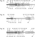
- Figure 8 shows a schematic representation of a section through parts of the component 14 shown in Figure 7 during its manufacture.
- the cutting plane of the Figure 8 corresponds to the cutting planes of the Figures 3, 4 and 7 .
- Figure 8 a situation is shown during the manufacture of the component, in which the wire 20 is already arranged in the channel 52 in the shaft tube 50.
- the proximal end 56 of the shaft tube 50 is inserted into the channel 65 in the first sleeve component 60.
- the shaft tube 50 is not yet rigidly connected to the first sleeve component 60, but can, as shown below with reference to the Figures 10 to 12 described, relative to the first sleeve component 60.
- the first sleeve component 60 has an external thread 67 which is provided and designed for positive and non-positive joining with a corresponding internal thread 76 at the distal end of the second sleeve component 70.
- Figure 9 shows another schematic representation of a section through the Figure 8 shown parts.
- the cutting plane of the Figure 9 corresponds to the cutting planes of the Figures 3, 4 , 7 and 8 .
- the first sleeve component 60 is connected by a screw connection between its external thread 67 (cf. Figure 8 ) with the internal thread 76 on the second sleeve component 70 is connected to the distal end of the second sleeve component 70.
- the first sleeve component 60 and the second sleeve component 70 can be connected to one another in a form-fitting, force-fitting and/or material-fitting manner.
- Figure 10 shows another schematic representation of a section through the Figures 8 and 9 shown parts.
- the cutting plane of the Figure 10 corresponds to the cutting planes of the Figures 3, 4 and 7 to 9 .
- the unit of the first sleeve component 60 and the second sleeve component 70 is displaced distally relative to the wire 20 and the shaft tube 50, so that the proximal end 23 of the wire 20 and optionally also as in Figure 10 As indicated, the proximal end 56 of the shaft tube 50 protrudes proximally from the channel 73 in the second sleeve component 70.
- Figure 11 shows a further schematic representation of a section through parts of the Figure 7 shown component 14 during its manufacture.
- the cutting plane of the Figure 11 corresponds to the cutting planes of the Figures 3, 4 and 7 to 10 .
- the proximal end 23 of the wire 20 protruding from the second sleeve component 70 is inserted into the first longitudinal bore 32 at the distal end of the first rod component 30.
- a transverse bore 33 is provided in the first rod component 30 in the region of the first longitudinal bore 32 in order to enable or simplify a material-locking joining of the proximal end 23 of the wire 20 to the distal end of the first rod component 30.
- the proximal end 23 of the wire 20 is laser-welded in the region of the transverse bore 33 is joined to the first rod component 30 in a material-locking manner.
- the proximal end 23 of the wire 20 and the first rod component 30 can be connected to one another in a form-fitting, force-fitting and/or material-locking manner in another way.
- a transverse bore 33 in the first rod component 30, as shown in the Figures 7 and 11 shown can also be used in the Figures 3 to 6 shown components may be provided.
- Figure 12 shows another schematic representation of a section through the Figure 11 shown parts.
- the cutting plane of the Figure 12 corresponds to the cutting planes of the Figures 3, 4 and 7 to 11 .
- the unit consisting of the first sleeve component 60 and the second sleeve component 70 is displaced proximally again relative to the shaft tube 50 and also relative to the transmission device 20, 30, 40.
- the Figure 12 The position shown of the unit comprising the first sleeve component 60 and the second sleeve component 70 relative to the proximal end 56 of the shaft tube 50 corresponds to the final position or the position intended for the finished component.
- the proximal end 56 of the shaft tube 50 is mechanically rigidly connected to the first sleeve component 60, for example by means of a circumferential laser weld seam or in another form-fitting, force-fitting and/or material-fitting manner.
- Figure 13 shows a further schematic representation of a section through parts of the Figure 7 shown component 14 during its manufacture.
- the cutting plane of the Figure 13 corresponds to the cutting planes of the Figures 3, 4 and 7 to 12 .
- the third sleeve component 80 is attached to the second sleeve component 70 in the manner provided and can be connected to it in a form-fitting, force-fitting and/or material-fitting manner.
- the connecting component 90 has to be slipped over the shaft tube 50, the first sleeve component 60 and the distal end of the second sleeve component 70 and joined thereto in a form-fitting, force-fitting and/or material-fitting manner.
- Figure 14 shows a schematic representation of a section through the proximal end of another component 14, which in some features, properties and functions corresponds to the Figures 3 to 13 components shown.
- the cutting plane of the Figure 14 corresponds to the cutting planes of the Figures 3, 4 and 7 to 13 .
- features and properties of component 14 are described in particular, in which they differ from the Figures 3 to 13 components shown.
- the components shown in Figure 14 Component 14 shown differs from the components shown in the Figures 3 to 13 shown components in particular in that only one rod component 30 is provided, which performs the functions of both rod components 30, 40 of the Figures 3 to 13
- the rod component 30 comprises, in particular, at its distal end, a longitudinal bore 32 in which the proximal end 23 of the wire 20 is arranged and fastened, and at its proximal end a coupling ball 49 for releasable mechanical coupling to a movable part 19 of a handling device 18 (cf. Figure 1 ).
- Component 14 shown differs from the components shown in the Figures 3 to 13 The components shown furthermore differ in that neither an annular collar nor one or more lugs are provided on the rod component 30. Rather, a pin 38 is provided in a corresponding transverse bore in the rod component 30. Both ends of the pin 38 protrude from the outer contour of the rod component 30 and each protrude into an elongated recess 85 in the shaft 50, 60, 70, 80. Proximally oriented stop surfaces 36 and distally oriented stop surfaces 37 of the transmission device 20, 30, 40 are formed by corresponding parts of the surfaces of the ends of the pin 38.
- the recesses 85 are formed by slots in the second sleeve component 70, which are closed off to the outside by a tubular section of the third sleeve component 80. Edge regions of the slots forming the recesses 85 in the second sleeve component 70 form the proximally oriented stop surface 78 and the distally oriented stop surface 86.
- Figure 15 shows a schematic representation of a section through parts of the component shown in Figure 14.
- the cutting plane of the Figure 15 corresponds to the cutting planes of the Figures 3, 4 and 7 to 14 .
- FIG 15 a situation is shown in which the first sleeve component 60 can already be mechanically rigidly connected to the proximal end 56 of the shaft tube 50. Furthermore, the proximal end 23 of the wire 20 is already mechanically rigidly connected to the distal end of the rod component 30, namely inserted into the longitudinal bore 32 at the distal end of the rod component 30. The proximal end of the rod component 30 is already partially inserted into the channel 73 in the second sleeve component 70. In the second sleeve component 70, opposing slots can be seen which form the recesses 85 and whose proximal and distal ends form the distally oriented stop surfaces 86 and the proximally oriented stop surfaces 78, respectively.
- the second sleeve component 70 can be displaced distally relative to the other components shown and connected to the first sleeve component 60, for example by screwing between an external thread 67 on the first sleeve component 60 and an internal thread 76 on the second sleeve component 70.
- Figure 16 shows another schematic representation of a section through parts of the Figure 14 shown component 14 during its manufacture.
- the cutting plane of the Figure 16 corresponds to the cutting planes of the Figures 3, 4 and 7 to 15 .
- the situation shown differs from that in Figure 15 shown situation in that the first sleeve component 60 is rigidly and in particular permanently mechanically connected to the second sleeve component 70.
- the pin 38 is already partially inserted through one of the two slots on the second sleeve component 70, which form the two recesses 85, into a corresponding transverse bore 39 in the rod component 30.
- the Figure 16 The third sleeve component 80, which is already shown slipped over the proximal end of the rod component 30, is attached to the proximal end of the second sleeve component 70 and is mechanically rigidly and in particular permanently connected thereto.
- the connecting component 90 can be slipped over the first sleeve component 60 and the distal end of the second sleeve component 70 from the distal end before or after this.
- a mechanically rigid connection between the connecting component 90 and the second sleeve component 70 is achieved in the Figures 3 to 16 illustrated examples are formed by engagement of an inwardly projecting collar at the proximal end of the connecting component 90 in a corresponding circumferential groove on the second sleeve component 70.
- the connecting component 90 can be formed in all of the Figures 3 to 16 shown components 14 are joined in a form-fitting, force-fitting and/or material-fitting manner to the shaft tube 50 and/or to the second sleeve component 70.
- Figure 17 shows a schematic flow diagram of a method for producing a component for a medical instrument, in particular one of the components described in the Figures 3 to 16
- the method is also suitable for producing a component with features, properties and functions that differ from those shown in the Figures 1 to 16 Nevertheless, reference symbols from the Figures 1 to 16 used as an example to simplify understanding.
- a distal end of a transmission device 16, 20, 30, 40 is coupled to a movable part of a tool 13.
- the tool 13 is intended in particular for gripping, holding, squeezing, cutting or punching and has, for example, a fixed branch or a fixed jaw part and a branch that can be pivoted relative to the fixed branch.
- the pivotable branch can be coupled directly to the distal end of the transmission device 16, 20, 30, 40 by a joint or indirectly via a connecting rod.
- the pivotable branch can be coupled in another way to the distal end of the transmission device 16, 20, 30, 40 in such a way that a translation of the transmission device 16, 20, 30, 40 is accompanied by a pivoting movement of the pivotable branch.
- a second step 102 the tool 13 is connected to the distal end of the shaft 15, 50, 60, 70, 80.
- the tool is connected in particular permanently or non-destructively releasably to the distal end of the shaft 15, 50, 60, 70, 80.
- a proximal end 56 of a shaft tube 50 is guided to a mounting position (cf. Figures 10 , 11 ) relative to a first component 60, 70 of a shaft 15, 50, 60, 70, 80 to be manufactured as part of the component to be manufactured into the first component 60, 70 of the shaft 15, 50, 60, 70, 80.
- the assembly position of the proximal end 56 of the shaft tube 50 (cf. Figures 10 , 11 ) is located proximal to the position intended for the finished component (cf. Figure 7 ) of the proximal end 56 of the shaft tube 50 relative to the first component 60, 70 of the shaft 15, 50, 60, 70, 80.
- the mounting position of the proximal end 56 of the shaft tube 50 can be proximal (cf. Figures 10, 11) or distal of the proximal end of the first component 60, 70 of the shaft 15, 50, 60, 70, 80.
- a proximal end 23 of a first component 20 of a transmission device 16, 20, 30, 40 is guided from distal to an assembly position (cf. Figures 10 , 11 ) is passed through the first component 60, 70 of the shaft 15, 50, 60, 70, 80.
- the assembly position of the proximal end 23 of the first component 20 relative to the first component 60, 70 of the shaft 15, 50, 60, 70, 80 is proximal to its position for the finished Component 14 provided position (cf. Figure 7 ).
- the mounting position of the proximal end 23 of the first component 20 of the transmission device 160, 20, 30, 40 is in particular proximal to the proximal end of the first component 60, 70 of the shaft 15, 50, 60, 70, 80.
- the first step 101, the second step 102, the third step 103 and the fourth step 104 are in particular carried out in the order given. Alternatively, these steps can be carried out in a different order, with the first step 101 and the second step 102 in particular being carried out before the third step 103 and/or before the fourth step 104. If the first step 101 and the second step 102 are carried out before the third step 103 and the fourth step 104, the third step 103 and the fourth step 104 can be carried out simultaneously.
- the first step 101, the second step 102 and the third step 103 are each optional and can be omitted.
- a fifth step 105 the proximal end 23 of the first component 20 of the transmission device 16, 20, 30, 40 is mechanically connected to a second component 30, 40 of the transmission device 16, 20, 30, 40.
- the mechanical connection produced in the fifth step 105 is in particular a permanent connection or a connection that cannot be released without causing damage.
- the second component 30, 40 of the transmission device 16, 20, 30, 40 and the first component 50, 60, 70 of the shaft 15, 50, 60, 70, 80 are in particular designed such that a movement of the second component 30, 40 of the transmission device 16, 20, 30, 40 relative to the first component 50, 60, 70 of the shaft 15, 50, 60, 70, 80 is limited distally by mechanical contact of corresponding stop surfaces 37, 78.
- proximal end 23 of the first component 20 of the transmission device 16, 20, 30, 40 is moved from the assembly position of the proximal end 23 of the first component 20 distally to a position intended for the finished component relative to the first component 60, 70 of the shaft 15, 50, 60, 70, 80.
- a seventh step 107 the proximal end 56 of the shaft tube 50 is moved distally relative to the first component of the shaft 15, 50, 60, 70, 80 to the position intended for use of the component 14.
- the sixth step 106 and the seventh step 107 are carried out simultaneously or in any order, but both after the fourth step 104 and the fifth step 105.
- the proximal end 56 of the shaft tube 50 is connected to the first component 60, 70 of the shaft 15, 50, 60, 70, 80.
- the eighth step 108 is carried out in particular after the seventh step 107, i.e. at the position of the proximal end 56 of the shaft tube 50 relative to the first component 60, 70 of the shaft 15, 50, 60, 70, 80 intended for the finished component 14.
Landscapes
- Health & Medical Sciences (AREA)
- Surgery (AREA)
- Life Sciences & Earth Sciences (AREA)
- Heart & Thoracic Surgery (AREA)
- Molecular Biology (AREA)
- Veterinary Medicine (AREA)
- Engineering & Computer Science (AREA)
- Biomedical Technology (AREA)
- Nuclear Medicine, Radiotherapy & Molecular Imaging (AREA)
- Medical Informatics (AREA)
- Public Health (AREA)
- Animal Behavior & Ethology (AREA)
- General Health & Medical Sciences (AREA)
- Pathology (AREA)
- Oral & Maxillofacial Surgery (AREA)
- Ophthalmology & Optometry (AREA)
- Surgical Instruments (AREA)
Claims (14)
- Composant (14) pour la liaison mécanique à une installation de manipulation (18) pour la formation d'un instrument médical (10), comportant :un arbre (15) ;une installation de transmission (16) mobile à l'intérieur de l'arbre (15) pour la transmission d'une force depuis une installation de manipulation (18) accouplée à l'extrémité proximale du composant (14) à un outil (13) à l'extrémité distale du composant (14) ;une surface de butée (86) sur l'arbre (15) ;une surface de butée (36) sur l'installation de transmission (16),dans lequel la surface de butée (86) de l'arbre (15) et la surface de butée (36) de l'installation de transmission (16) sont agencées de telle sorte qu'un contact mécanique entre la surface de butée (36) de l'installation de transmission (16) et la surface de butée (86) de l'arbre (15) limite un mouvement de l'installation de transmission (16) par rapport à l'arbre (15) vers le côté proximal,caractérisé en ce que l'installation de transmission (16) présente, dans une section (20) distale par rapport à la surface de butée (36) de l'installation de transmission (16) sa surface en section transversale minimale,toutes les surfaces en section transversale de l'installation de transmission (16) proximales par rapport à la surface de butée (36) de l'installation de transmission (16) sont plus grandes que la surface en section transversale minimale de l'installation de transmission (16).
- Composant (14) selon la revendication précédente, dans lequella surface de butée (86) de l'arbre (15) et la surface de butée (36) de l'installation de transmission (16) sont agencées de telle sorte qu'un contact mécanique entre la surface de butée (36) de l'installation de transmission (16) et la surface de butée (86) de l'arbre (15) limite, lors de l'utilisation prévue, une déformation élastique de l'installation de transmission (16) par une force transmise par l'installation de transmission (16) à une valeur maximale prédéterminée,la valeur maximale prédéterminée de déformation élastique et les propriétés élastiques de l'installation de transmission (16) sont choisis de manière à ce que, pour la force présente à la valeur maximale prédéterminée de la déformation élastique de l'installation de transmission (16), une destruction ou un endommagement de l'arbre (15), de l'installation de transmission (16) et d'un outil (13) relié à l'extrémité distale de l'arbre (15) et accouplé à l'extrémité distale de l'installation de transmission (16) sont exclus.
- Composant (14) selon la revendication précédente, dans lequel la destruction ou l'endommagement de l'arbre (15), de l'installation de transmission (16) et d'un outil (13) accouplé à l'extrémité distale de l'arbre (15) sont également exclus lorsque l'outil (13) est bloqué dans un état complètement ouvert ou dans un état complètement fermé ou dans un état quelconque.
- Composant (14) selon l'une des revendications précédentes, dans lequel la surface de butée (86) de l'arbre (15) est agencée à proximité de l'extrémité proximale de l'arbre (15) et la surface de butée (36) de l'installation de transmission (16) est agencée à proximité de l'extrémité proximale de l'installation de transmission (16).
- Composant (14) selon l'une des revendications précédentes, dans lequell'installation de transmission (16) est élastiquement déformable de manière distale par rapport à la surface de butée (36) de l'installation de transmission (16) jusqu'à une première force maximale,l'installation de transmission (16) est élastiquement déformable de manière proximale par rapport à la surface de butée (36) de l'installation de transmission (16) à une seconde force maximale,la seconde force maximale est supérieure à la première force maximale.
- Composant (14) selon l'une des revendications précédentes, comportant en outre :une surface de butée supplémentaire (78) sur l'arbre (15) ;une surface de butée supplémentaire (37) sur l'installation de transmission (16),dans lequel la surface de butée supplémentaire (78) de l'arbre (15) et la surface de butée supplémentaire (37) de l'installation de transmission (16) sont agencées de telle sorte qu'un contact mécanique entre la surface de butée supplémentaire (37) de l'installation de transmission (16) et la surface de butée supplémentaire (78) de l'arbre (15) limite un mouvement de l'installation de transmission (16) par rapport à l'arbre (15) vers le côté distal.
- Composant (14) selon l'une des revendications précédentes, dans lequell'installation de transmission (16) présente une collerette (35) faisant saillie vers l'extérieur,l'arbre (15) présente une rainure (85) qui élargit un canal (83) dans lequel est agencée l'installation de transmission (16),la collerette (35) de l'installation de transmission (16) est agencée dans la rainure (85) de l'arbre (15),la surface de butée (86) de l'arbre (15) fait partie de la surface intérieure de la rainure (85),la surface de butée (36) de l'installation de transmission (16) fait partie de la surface de la collerette (35).
- Composant (14) selon l'une des revendications précédentes, dans lequell'installation de transmission (16) présente une saillie, un nez, un nervure, un tenon ou une autre zone convexe (38),l'arbre (15) présente une rainure ou un autre évidement (85) en forme de niche qui s'étend depuis un canal (83) dans lequel est agencée l'installation de transmission (16) la saillie ou le nez ou la nervure ou le tenon ou l'autre zone convexe (38) de l'installation de transmission (16) est agencé dans la rainure ou l'autre évidement (85) en forme de niche de l'arbre (15),la surface de butée (86) de l'arbre (15) fait partie de la surface intérieure de la rainure ou de l'autre évidement (85) en forme de niche de l'arbre (15),la surface de butée (36) de l'installation de transmission (16) fait partie de la surface de la saillie ou du nez ou de la nervure ou du tenon ou de l'autre zone convexe (38).
- Composant (14) selon l'une des revendications précédentes, comportant en outre :un outil (13) à l'extrémité distale de l'arbre (15),dans lequel l'outil (13) présente un élément de construction mobile qui est accouplé à l'extrémité distale de l'installation de transmission (16).
- Instrument médical (10) comportant :un composant (14) selon l'une des revendications précédentes ;une installation de manipulation (18), qui est accouplée ou peut être couplée à l'extrémité proximale de l'arbre (15).
- Procédé de fabrication d'un composant (14) pouvant être relié mécaniquement à une installation de manipulation (18) selon l'une des revendications 1 à 9 pour un instrument médical (10) comportant les étapes suivantes :passage (104) d'une extrémité proximale (23) d'un premier élément de construction (20) d'une installation de transmission (16, 20, 30, 40) depuis le côté distal à travers un premier élément de construction (60, 70) d'un arbre (15, 50, 60 , 70, 80) vers une position d'assemblage qui est proximale à la position prévue pour le composant (14) fini par rapport au premier élément de construction (60, 70) de l'arbre (15, 50, 60, 70, 80) ;liaison mécanique (105) de l'extrémité proximale (23) du premier élément de construction (20) de l'installation de transmission (16, 20, 30, 40) avec un second élément de construction (30, 40) de l'installation de transmission (16, 20, 30, 40) ;déplacement (106) de l'extrémité proximale (23) du premier élément de construction (20) de l'installation de transmission (16, 20, 30, 40) vers le côté distal jusqu'à une position prévue pour le composant (14) fini par rapport au premier élément de construction (60, 70) de l'arbre (15, 50, 60, 70, 80).
- Procédé selon la revendication précédente, comportant en outre les étapes suivantes :introduction (103) d'une extrémité proximale (56) d'un tube d'arbre (50) dans le premier élément de construction (60, 70) de l'arbre (15, 50, 60, 70, 80) jusqu'à une position de montage qui est proximale à la position prévue pour le composant (14) fini par rapport au premier élément de construction (60, 70) de l'arbre (15, 50, 60, 70, 80), avant la liaison (10) de l'extrémité proximale (23) du premier élément de construction (20) de l'installation de transmission (16, 20, 30, 40) avec le second élément de construction (30, 40) de l'installation de transmission (16, 20, 30, 40) ;déplacement (107) de l'extrémité proximale (56) du tube d'arbre (50) par rapport au premier élément de construction (60, 70) de l'arbre (15, 50, 60, 70, 80) vers le côté distal jusqu'à la position (60, 70) prévue pour l'utilisation du composant (14) du tube d'arbre (50) par rapport au premier élément de construction (60, 70) de l'arbre (15, 50, 60, 70, 80) après la liaison (10) de l'extrémité proximale (23) du premier élément de construction (20) de l'installation de transmission (16, 20, 30, 40) avec un second élément de construction (30, 40) de l'installation de transmission (16, 20, 30, 40) ;liaison mécanique (108) de l'extrémité proximale (56) du tube d'arbre (50) avec le premier élément de construction (60, 70) de l'arbre (15, 50, 60, 70, 80) à la position prévue pour le composant (14) fini par rapport au premier élément de construction (60, 70) de l'arbre (15, 50, 60, 70, 80).
- Procédé selon l'une des revendications 11 et 12, comportant en outre les étapes suivantes :accouplement (101) d'une extrémité distale de l'installation de transmission (16, 20, 30, 40) avec une partie mobile d'un outil (13) ;liaison mécanique (102) de l'outil (13) avec une extrémité distale de l'arbre (15, 50, 60, 70, 80).
- Procédé selon la revendication précédente, dans lequel au moins soit l'étape d'accouplement (101) de l'extrémité distale de l'installation detransmission (16, 20, 30, 40) avec une partie mobile de l'outil (13) soit l'étape de liaison mécanique (102) de l'outil (13) à l'extrémité distale de l'arbre (15, 50, 60, 70, 80) sont effectuées au moins soit avant l'étape d'introduction (103) de l'extrémité proximale (56) du tube d'arbre (50) dans le premier élément de construction (60, 70) del'arbre (15, 50, 60, 70, 80) soit avant l'étape de passage (104) de l'extrémité proximale (23) du premier élément de construction (20) de l'installation detransmission (16, 20, 30, 40) depuis le côté distal à travers le premier élément de construction (60, 70) de l'arbre (15, 50, 60, 70, 80).
Applications Claiming Priority (1)
| Application Number | Priority Date | Filing Date | Title |
|---|---|---|---|
| DE102016118304.0A DE102016118304A1 (de) | 2016-09-28 | 2016-09-28 | Komponente für ein medizinisches Instrument und medizinisches Instrument |
Publications (2)
| Publication Number | Publication Date |
|---|---|
| EP3300675A1 EP3300675A1 (fr) | 2018-04-04 |
| EP3300675B1 true EP3300675B1 (fr) | 2024-08-07 |
Family
ID=59923295
Family Applications (1)
| Application Number | Title | Priority Date | Filing Date |
|---|---|---|---|
| EP17192042.4A Active EP3300675B1 (fr) | 2016-09-28 | 2017-09-20 | Composants pour un instrument médical et instrument médical |
Country Status (3)
| Country | Link |
|---|---|
| US (1) | US10842584B2 (fr) |
| EP (1) | EP3300675B1 (fr) |
| DE (1) | DE102016118304A1 (fr) |
Families Citing this family (2)
| Publication number | Priority date | Publication date | Assignee | Title |
|---|---|---|---|---|
| US12042128B2 (en) * | 2019-11-26 | 2024-07-23 | Karl Storz Se & Co. Kg | Endoscope device for a flexible endoscope, and method for producing an endoscope device |
| DE102024139321B3 (de) | 2024-12-20 | 2026-04-23 | Karl Storz Se & Co. Kg | Adaptervorrichtung, zerlegbares medizinisches Schaftinstrument und Verfahren zum Reinigen des zerlegbaren medizinischen Schaftinstruments und Montageverfahren |
Citations (2)
| Publication number | Priority date | Publication date | Assignee | Title |
|---|---|---|---|---|
| US4569131A (en) * | 1983-06-01 | 1986-02-11 | Richard Wolf Gmbh | Tool having a handle with an interchangeable insert portion |
| DE4311770A1 (de) * | 1992-04-09 | 1993-10-28 | Olympus Optical Co | Greifpinzette für medizinische Behandlungen |
Family Cites Families (12)
| Publication number | Priority date | Publication date | Assignee | Title |
|---|---|---|---|---|
| DE69534011T8 (de) * | 1994-07-29 | 2006-07-06 | Olympus Optical Co., Ltd. | Medizinisches Instrument zur Benutzung in Kombination mit Endoskopen |
| DE19731453C2 (de) | 1997-07-22 | 1999-07-22 | Storz Karl Gmbh & Co | Vorrichtung zum Begrenzen der Kraftübertragung an chirurgischen Instrumenten |
| JP4480978B2 (ja) * | 2003-10-08 | 2010-06-16 | オリンパス株式会社 | 医療用処置具 |
| US8025621B2 (en) | 2005-07-26 | 2011-09-27 | Microline Surgical, Inc. | Medical device with adjustable inner shaft movement |
| US8043301B2 (en) * | 2007-10-12 | 2011-10-25 | Spiration, Inc. | Valve loader method, system, and apparatus |
| DE102009031262A1 (de) | 2009-06-30 | 2011-01-05 | Karl Storz Gmbh & Co. Kg | Medizinisches Instrument |
| DE102011007121A1 (de) | 2011-04-11 | 2012-10-11 | Karl Storz Gmbh & Co. Kg | Handhabungseinrichtung für ein mikroinvasiv-chirurgisches Instrument |
| DE102011007119A1 (de) | 2011-04-11 | 2012-10-11 | Karl Storz Gmbh & Co. Kg | Handhabungseinrichtung für ein mikroinvasiv-chirurgisches Instrument |
| DE102011081464A1 (de) * | 2011-08-24 | 2013-02-28 | Karl Storz Gmbh & Co. Kg | Werkzeug für ein mikroinvasiv-chirurgisches Instrument |
| EP2591737B1 (fr) * | 2011-11-11 | 2016-11-02 | Karl Storz GmbH & Co. KG | Instrument chirurgical |
| DE102012002770A1 (de) | 2012-02-11 | 2013-08-14 | Karl Storz Gmbh & Co. Kg | Medizinisches Instrument |
| US10702278B2 (en) * | 2014-12-02 | 2020-07-07 | Covidien Lp | Laparoscopic surgical ligation clip applier |
-
2016
- 2016-09-28 DE DE102016118304.0A patent/DE102016118304A1/de active Pending
-
2017
- 2017-09-20 EP EP17192042.4A patent/EP3300675B1/fr active Active
- 2017-09-27 US US15/717,068 patent/US10842584B2/en active Active
Patent Citations (2)
| Publication number | Priority date | Publication date | Assignee | Title |
|---|---|---|---|---|
| US4569131A (en) * | 1983-06-01 | 1986-02-11 | Richard Wolf Gmbh | Tool having a handle with an interchangeable insert portion |
| DE4311770A1 (de) * | 1992-04-09 | 1993-10-28 | Olympus Optical Co | Greifpinzette für medizinische Behandlungen |
Also Published As
| Publication number | Publication date |
|---|---|
| DE102016118304A1 (de) | 2018-03-29 |
| US10842584B2 (en) | 2020-11-24 |
| US20180085181A1 (en) | 2018-03-29 |
| EP3300675A1 (fr) | 2018-04-04 |
Similar Documents
| Publication | Publication Date | Title |
|---|---|---|
| EP2612609B1 (fr) | Instrument médical | |
| DE112016005391T5 (de) | Verbindungsstruktur und verbindungsverfahren | |
| EP2674117B1 (fr) | Dispositif de transmission pour la transmission d'une force et d'un couple dans un instrument médical | |
| EP3380026B1 (fr) | Instrument de manipulation pour une vis de fixation osseuse | |
| EP1055397A1 (fr) | Instrument médical de préparation de tissus | |
| DE102006032430A1 (de) | Medizinisches Gerät | |
| EP3300675B1 (fr) | Composants pour un instrument médical et instrument médical | |
| EP2732778B1 (fr) | Instrument médical | |
| EP3097873B1 (fr) | Outil pour un instrument medical demontable | |
| EP4091558A1 (fr) | Instrument endoscopique, ainsi que manche et insert d'instrument pour un instrument endoscopique | |
| DE102009001278A1 (de) | Medizinisches Instrument | |
| EP1587434B1 (fr) | Instrument medical pour la dissection de tissus | |
| EP1303219B1 (fr) | Instrument medical, notamment resectoscope | |
| DE102008064424B4 (de) | Steck-Kupplungs-Vorrichtung | |
| DE202007000427U1 (de) | Chirurgischer Haltegriff und chirurgisches Instrument | |
| DE102022116372B4 (de) | Chirurgisches instrument und verfahren zu dessen zerlegung | |
| DE19908593C2 (de) | Chirurgisches Instrument | |
| DE102015204486A1 (de) | Chirurgisches Instrument | |
| DE60205934T2 (de) | Schneideinsatz-Antriebswelle Verbindung | |
| DE102013003316B4 (de) | Chirurgisches Maulinstrument | |
| DE102007007904B3 (de) | Kupplung für ein Rohrschaftinstrument | |
| DE102024111699A1 (de) | Chirurgisches Schaftinstrument sowie Verfahren zum Herstellen eines chirurgischen Schaftsinstruments | |
| WO2016124318A1 (fr) | Pince chirurgicale comprenant une partie formant mâchoire réalisée en deux parties | |
| DE102013217614B3 (de) | Stent-Falt- und Ladevorrichtung sowie Bronchoskopsystem | |
| DE29911011U1 (de) | Medizinische Zange |
Legal Events
| Date | Code | Title | Description |
|---|---|---|---|
| PUAI | Public reference made under article 153(3) epc to a published international application that has entered the european phase |
Free format text: ORIGINAL CODE: 0009012 |
|
| STAA | Information on the status of an ep patent application or granted ep patent |
Free format text: STATUS: THE APPLICATION HAS BEEN PUBLISHED |
|
| AK | Designated contracting states |
Kind code of ref document: A1 Designated state(s): AL AT BE BG CH CY CZ DE DK EE ES FI FR GB GR HR HU IE IS IT LI LT LU LV MC MK MT NL NO PL PT RO RS SE SI SK SM TR |
|
| AX | Request for extension of the european patent |
Extension state: BA ME |
|
| STAA | Information on the status of an ep patent application or granted ep patent |
Free format text: STATUS: REQUEST FOR EXAMINATION WAS MADE |
|
| 17P | Request for examination filed |
Effective date: 20181002 |
|
| RBV | Designated contracting states (corrected) |
Designated state(s): AL AT BE BG CH CY CZ DE DK EE ES FI FR GB GR HR HU IE IS IT LI LT LU LV MC MK MT NL NO PL PT RO RS SE SI SK SM TR |
|
| STAA | Information on the status of an ep patent application or granted ep patent |
Free format text: STATUS: EXAMINATION IS IN PROGRESS |
|
| 17Q | First examination report despatched |
Effective date: 20210315 |
|
| P01 | Opt-out of the competence of the unified patent court (upc) registered |
Effective date: 20230527 |
|
| GRAP | Despatch of communication of intention to grant a patent |
Free format text: ORIGINAL CODE: EPIDOSNIGR1 |
|
| STAA | Information on the status of an ep patent application or granted ep patent |
Free format text: STATUS: GRANT OF PATENT IS INTENDED |
|
| INTG | Intention to grant announced |
Effective date: 20240405 |
|
| RIN1 | Information on inventor provided before grant (corrected) |
Inventor name: KAERCHER, DANIEL Inventor name: STEFAN, JOCHEN |
|
| GRAS | Grant fee paid |
Free format text: ORIGINAL CODE: EPIDOSNIGR3 |
|
| GRAA | (expected) grant |
Free format text: ORIGINAL CODE: 0009210 |
|
| STAA | Information on the status of an ep patent application or granted ep patent |
Free format text: STATUS: THE PATENT HAS BEEN GRANTED |
|
| AK | Designated contracting states |
Kind code of ref document: B1 Designated state(s): AL AT BE BG CH CY CZ DE DK EE ES FI FR GB GR HR HU IE IS IT LI LT LU LV MC MK MT NL NO PL PT RO RS SE SI SK SM TR |
|
| REG | Reference to a national code |
Ref country code: GB Ref legal event code: FG4D Free format text: NOT ENGLISH |
|
| REG | Reference to a national code |
Ref country code: CH Ref legal event code: EP |
|
| REG | Reference to a national code |
Ref country code: IE Ref legal event code: FG4D Free format text: LANGUAGE OF EP DOCUMENT: GERMAN |
|
| REG | Reference to a national code |
Ref country code: DE Ref legal event code: R096 Ref document number: 502017016323 Country of ref document: DE |
|
| REG | Reference to a national code |
Ref country code: LT Ref legal event code: MG9D |
|
| REG | Reference to a national code |
Ref country code: NL Ref legal event code: MP Effective date: 20240807 |
|
| PG25 | Lapsed in a contracting state [announced via postgrant information from national office to epo] |
Ref country code: NO Free format text: LAPSE BECAUSE OF FAILURE TO SUBMIT A TRANSLATION OF THE DESCRIPTION OR TO PAY THE FEE WITHIN THE PRESCRIBED TIME-LIMIT Effective date: 20241107 |
|
| PG25 | Lapsed in a contracting state [announced via postgrant information from national office to epo] |
Ref country code: FI Free format text: LAPSE BECAUSE OF FAILURE TO SUBMIT A TRANSLATION OF THE DESCRIPTION OR TO PAY THE FEE WITHIN THE PRESCRIBED TIME-LIMIT Effective date: 20240807 Ref country code: PT Free format text: LAPSE BECAUSE OF FAILURE TO SUBMIT A TRANSLATION OF THE DESCRIPTION OR TO PAY THE FEE WITHIN THE PRESCRIBED TIME-LIMIT Effective date: 20241209 Ref country code: GR Free format text: LAPSE BECAUSE OF FAILURE TO SUBMIT A TRANSLATION OF THE DESCRIPTION OR TO PAY THE FEE WITHIN THE PRESCRIBED TIME-LIMIT Effective date: 20241108 Ref country code: PL Free format text: LAPSE BECAUSE OF FAILURE TO SUBMIT A TRANSLATION OF THE DESCRIPTION OR TO PAY THE FEE WITHIN THE PRESCRIBED TIME-LIMIT Effective date: 20240807 Ref country code: NL Free format text: LAPSE BECAUSE OF FAILURE TO SUBMIT A TRANSLATION OF THE DESCRIPTION OR TO PAY THE FEE WITHIN THE PRESCRIBED TIME-LIMIT Effective date: 20240807 |
|
| PG25 | Lapsed in a contracting state [announced via postgrant information from national office to epo] |
Ref country code: BG Free format text: LAPSE BECAUSE OF FAILURE TO SUBMIT A TRANSLATION OF THE DESCRIPTION OR TO PAY THE FEE WITHIN THE PRESCRIBED TIME-LIMIT Effective date: 20240807 |
|
| PG25 | Lapsed in a contracting state [announced via postgrant information from national office to epo] |
Ref country code: LV Free format text: LAPSE BECAUSE OF FAILURE TO SUBMIT A TRANSLATION OF THE DESCRIPTION OR TO PAY THE FEE WITHIN THE PRESCRIBED TIME-LIMIT Effective date: 20240807 |
|
| PG25 | Lapsed in a contracting state [announced via postgrant information from national office to epo] |
Ref country code: IS Free format text: LAPSE BECAUSE OF FAILURE TO SUBMIT A TRANSLATION OF THE DESCRIPTION OR TO PAY THE FEE WITHIN THE PRESCRIBED TIME-LIMIT Effective date: 20241207 |
|
| PG25 | Lapsed in a contracting state [announced via postgrant information from national office to epo] |
Ref country code: HR Free format text: LAPSE BECAUSE OF FAILURE TO SUBMIT A TRANSLATION OF THE DESCRIPTION OR TO PAY THE FEE WITHIN THE PRESCRIBED TIME-LIMIT Effective date: 20240807 |
|
| PG25 | Lapsed in a contracting state [announced via postgrant information from national office to epo] |
Ref country code: ES Free format text: LAPSE BECAUSE OF FAILURE TO SUBMIT A TRANSLATION OF THE DESCRIPTION OR TO PAY THE FEE WITHIN THE PRESCRIBED TIME-LIMIT Effective date: 20240807 Ref country code: RS Free format text: LAPSE BECAUSE OF FAILURE TO SUBMIT A TRANSLATION OF THE DESCRIPTION OR TO PAY THE FEE WITHIN THE PRESCRIBED TIME-LIMIT Effective date: 20241107 |
|
| PG25 | Lapsed in a contracting state [announced via postgrant information from national office to epo] |
Ref country code: RS Free format text: LAPSE BECAUSE OF FAILURE TO SUBMIT A TRANSLATION OF THE DESCRIPTION OR TO PAY THE FEE WITHIN THE PRESCRIBED TIME-LIMIT Effective date: 20241107 Ref country code: PT Free format text: LAPSE BECAUSE OF FAILURE TO SUBMIT A TRANSLATION OF THE DESCRIPTION OR TO PAY THE FEE WITHIN THE PRESCRIBED TIME-LIMIT Effective date: 20241209 Ref country code: PL Free format text: LAPSE BECAUSE OF FAILURE TO SUBMIT A TRANSLATION OF THE DESCRIPTION OR TO PAY THE FEE WITHIN THE PRESCRIBED TIME-LIMIT Effective date: 20240807 Ref country code: NO Free format text: LAPSE BECAUSE OF FAILURE TO SUBMIT A TRANSLATION OF THE DESCRIPTION OR TO PAY THE FEE WITHIN THE PRESCRIBED TIME-LIMIT Effective date: 20241107 Ref country code: NL Free format text: LAPSE BECAUSE OF FAILURE TO SUBMIT A TRANSLATION OF THE DESCRIPTION OR TO PAY THE FEE WITHIN THE PRESCRIBED TIME-LIMIT Effective date: 20240807 Ref country code: LV Free format text: LAPSE BECAUSE OF FAILURE TO SUBMIT A TRANSLATION OF THE DESCRIPTION OR TO PAY THE FEE WITHIN THE PRESCRIBED TIME-LIMIT Effective date: 20240807 Ref country code: IS Free format text: LAPSE BECAUSE OF FAILURE TO SUBMIT A TRANSLATION OF THE DESCRIPTION OR TO PAY THE FEE WITHIN THE PRESCRIBED TIME-LIMIT Effective date: 20241207 Ref country code: HR Free format text: LAPSE BECAUSE OF FAILURE TO SUBMIT A TRANSLATION OF THE DESCRIPTION OR TO PAY THE FEE WITHIN THE PRESCRIBED TIME-LIMIT Effective date: 20240807 Ref country code: GR Free format text: LAPSE BECAUSE OF FAILURE TO SUBMIT A TRANSLATION OF THE DESCRIPTION OR TO PAY THE FEE WITHIN THE PRESCRIBED TIME-LIMIT Effective date: 20241108 Ref country code: FI Free format text: LAPSE BECAUSE OF FAILURE TO SUBMIT A TRANSLATION OF THE DESCRIPTION OR TO PAY THE FEE WITHIN THE PRESCRIBED TIME-LIMIT Effective date: 20240807 Ref country code: ES Free format text: LAPSE BECAUSE OF FAILURE TO SUBMIT A TRANSLATION OF THE DESCRIPTION OR TO PAY THE FEE WITHIN THE PRESCRIBED TIME-LIMIT Effective date: 20240807 Ref country code: BG Free format text: LAPSE BECAUSE OF FAILURE TO SUBMIT A TRANSLATION OF THE DESCRIPTION OR TO PAY THE FEE WITHIN THE PRESCRIBED TIME-LIMIT Effective date: 20240807 |
|
| PG25 | Lapsed in a contracting state [announced via postgrant information from national office to epo] |
Ref country code: RO Free format text: LAPSE BECAUSE OF FAILURE TO SUBMIT A TRANSLATION OF THE DESCRIPTION OR TO PAY THE FEE WITHIN THE PRESCRIBED TIME-LIMIT Effective date: 20240807 Ref country code: DK Free format text: LAPSE BECAUSE OF FAILURE TO SUBMIT A TRANSLATION OF THE DESCRIPTION OR TO PAY THE FEE WITHIN THE PRESCRIBED TIME-LIMIT Effective date: 20240807 Ref country code: SM Free format text: LAPSE BECAUSE OF FAILURE TO SUBMIT A TRANSLATION OF THE DESCRIPTION OR TO PAY THE FEE WITHIN THE PRESCRIBED TIME-LIMIT Effective date: 20240807 |
|
| PG25 | Lapsed in a contracting state [announced via postgrant information from national office to epo] |
Ref country code: EE Free format text: LAPSE BECAUSE OF FAILURE TO SUBMIT A TRANSLATION OF THE DESCRIPTION OR TO PAY THE FEE WITHIN THE PRESCRIBED TIME-LIMIT Effective date: 20240807 |
|
| PG25 | Lapsed in a contracting state [announced via postgrant information from national office to epo] |
Ref country code: CZ Free format text: LAPSE BECAUSE OF FAILURE TO SUBMIT A TRANSLATION OF THE DESCRIPTION OR TO PAY THE FEE WITHIN THE PRESCRIBED TIME-LIMIT Effective date: 20240807 |
|
| PG25 | Lapsed in a contracting state [announced via postgrant information from national office to epo] |
Ref country code: SK Free format text: LAPSE BECAUSE OF FAILURE TO SUBMIT A TRANSLATION OF THE DESCRIPTION OR TO PAY THE FEE WITHIN THE PRESCRIBED TIME-LIMIT Effective date: 20240807 |
|
| REG | Reference to a national code |
Ref country code: CH Ref legal event code: PL |
|
| REG | Reference to a national code |
Ref country code: DE Ref legal event code: R097 Ref document number: 502017016323 Country of ref document: DE |
|
| PG25 | Lapsed in a contracting state [announced via postgrant information from national office to epo] |
Ref country code: LU Free format text: LAPSE BECAUSE OF NON-PAYMENT OF DUE FEES Effective date: 20240920 |
|
| PLBE | No opposition filed within time limit |
Free format text: ORIGINAL CODE: 0009261 |
|
| STAA | Information on the status of an ep patent application or granted ep patent |
Free format text: STATUS: NO OPPOSITION FILED WITHIN TIME LIMIT |
|
| PG25 | Lapsed in a contracting state [announced via postgrant information from national office to epo] |
Ref country code: MC Free format text: LAPSE BECAUSE OF FAILURE TO SUBMIT A TRANSLATION OF THE DESCRIPTION OR TO PAY THE FEE WITHIN THE PRESCRIBED TIME-LIMIT Effective date: 20240807 |
|
| REG | Reference to a national code |
Ref country code: BE Ref legal event code: MM Effective date: 20240930 |
|
| PG25 | Lapsed in a contracting state [announced via postgrant information from national office to epo] |
Ref country code: BE Free format text: LAPSE BECAUSE OF NON-PAYMENT OF DUE FEES Effective date: 20240930 |
|
| 26N | No opposition filed |
Effective date: 20250508 |
|
| PG25 | Lapsed in a contracting state [announced via postgrant information from national office to epo] |
Ref country code: CH Free format text: LAPSE BECAUSE OF NON-PAYMENT OF DUE FEES Effective date: 20240930 |
|
| PG25 | Lapsed in a contracting state [announced via postgrant information from national office to epo] |
Ref country code: IE Free format text: LAPSE BECAUSE OF NON-PAYMENT OF DUE FEES Effective date: 20240920 |
|
| PG25 | Lapsed in a contracting state [announced via postgrant information from national office to epo] |
Ref country code: SE Free format text: LAPSE BECAUSE OF FAILURE TO SUBMIT A TRANSLATION OF THE DESCRIPTION OR TO PAY THE FEE WITHIN THE PRESCRIBED TIME-LIMIT Effective date: 20240807 |
|
| PGFP | Annual fee paid to national office [announced via postgrant information from national office to epo] |
Ref country code: DE Payment date: 20250926 Year of fee payment: 9 |
|
| PGFP | Annual fee paid to national office [announced via postgrant information from national office to epo] |
Ref country code: GB Payment date: 20250923 Year of fee payment: 9 |
|
| PGFP | Annual fee paid to national office [announced via postgrant information from national office to epo] |
Ref country code: FR Payment date: 20250925 Year of fee payment: 9 |
|
| REG | Reference to a national code |
Ref country code: AT Ref legal event code: MM01 Ref document number: 1710043 Country of ref document: AT Kind code of ref document: T Effective date: 20240920 |
|
| PG25 | Lapsed in a contracting state [announced via postgrant information from national office to epo] |
Ref country code: AT Free format text: LAPSE BECAUSE OF NON-PAYMENT OF DUE FEES Effective date: 20240920 |
|
| PG25 | Lapsed in a contracting state [announced via postgrant information from national office to epo] |
Ref country code: IT Free format text: LAPSE BECAUSE OF NON-PAYMENT OF DUE FEES Effective date: 20240920 |
|
| PG25 | Lapsed in a contracting state [announced via postgrant information from national office to epo] |
Ref country code: CY Free format text: LAPSE BECAUSE OF FAILURE TO SUBMIT A TRANSLATION OF THE DESCRIPTION OR TO PAY THE FEE WITHIN THE PRESCRIBED TIME-LIMIT; INVALID AB INITIO Effective date: 20170920 |
|
| PG25 | Lapsed in a contracting state [announced via postgrant information from national office to epo] |
Ref country code: HU Free format text: LAPSE BECAUSE OF FAILURE TO SUBMIT A TRANSLATION OF THE DESCRIPTION OR TO PAY THE FEE WITHIN THE PRESCRIBED TIME-LIMIT; INVALID AB INITIO Effective date: 20170920 |
|
| PG25 | Lapsed in a contracting state [announced via postgrant information from national office to epo] |
Ref country code: IT Free format text: LAPSE BECAUSE OF NON-PAYMENT OF DUE FEES Effective date: 20240920 |
|
| PGFP | Annual fee paid to national office [announced via postgrant information from national office to epo] |
Ref country code: IT Payment date: 20250922 Year of fee payment: 9 |
|
| PGRI | Patent reinstated in contracting state [announced from national office to epo] |
Ref country code: IT Effective date: 20250131 |