EP3300913B1 - Cartouche de ruban adhésif, rouleau de ruban adhésif et procédé de fabrication d'un rouleau de ruban adhésif - Google Patents
Cartouche de ruban adhésif, rouleau de ruban adhésif et procédé de fabrication d'un rouleau de ruban adhésif Download PDFInfo
- Publication number
- EP3300913B1 EP3300913B1 EP17193274.2A EP17193274A EP3300913B1 EP 3300913 B1 EP3300913 B1 EP 3300913B1 EP 17193274 A EP17193274 A EP 17193274A EP 3300913 B1 EP3300913 B1 EP 3300913B1
- Authority
- EP
- European Patent Office
- Prior art keywords
- adhesive layer
- adhesive
- layer
- pigment
- tape
- Prior art date
- Legal status (The legal status is an assumption and is not a legal conclusion. Google has not performed a legal analysis and makes no representation as to the accuracy of the status listed.)
- Active
Links
Images
















Classifications
-
- C—CHEMISTRY; METALLURGY
- C09—DYES; PAINTS; POLISHES; NATURAL RESINS; ADHESIVES; COMPOSITIONS NOT OTHERWISE PROVIDED FOR; APPLICATIONS OF MATERIALS NOT OTHERWISE PROVIDED FOR
- C09J—ADHESIVES; NON-MECHANICAL ASPECTS OF ADHESIVE PROCESSES IN GENERAL; ADHESIVE PROCESSES NOT PROVIDED FOR ELSEWHERE; USE OF MATERIALS AS ADHESIVES
- C09J7/00—Adhesives in the form of films or foils
- C09J7/30—Adhesives in the form of films or foils characterised by the adhesive composition
-
- B—PERFORMING OPERATIONS; TRANSPORTING
- B65—CONVEYING; PACKING; STORING; HANDLING THIN OR FILAMENTARY MATERIAL
- B65H—HANDLING THIN OR FILAMENTARY MATERIAL, e.g. SHEETS, WEBS, CABLES
- B65H35/00—Delivering articles from cutting or line-perforating machines; Article or web delivery apparatus incorporating cutting or line-perforating devices, e.g. adhesive tape dispensers
- B65H35/0006—Article or web delivery apparatus incorporating cutting or line-perforating devices
- B65H35/002—Hand-held or table apparatus
- B65H35/0026—Hand-held or table apparatus for delivering pressure-sensitive adhesive tape
-
- B—PERFORMING OPERATIONS; TRANSPORTING
- B41—PRINTING; LINING MACHINES; TYPEWRITERS; STAMPS
- B41J—TYPEWRITERS; SELECTIVE PRINTING MECHANISMS, i.e. MECHANISMS PRINTING OTHERWISE THAN FROM A FORME; CORRECTION OF TYPOGRAPHICAL ERRORS
- B41J15/00—Devices or arrangements of selective printing mechanisms, e.g. ink-jet printers or thermal printers, specially adapted for supporting or handling copy material in continuous form, e.g. webs
- B41J15/04—Supporting, feeding, or guiding devices; Mountings for web rolls or spindles
- B41J15/044—Cassettes or cartridges containing continuous copy material, tape, for setting into printing devices
-
- C—CHEMISTRY; METALLURGY
- C09—DYES; PAINTS; POLISHES; NATURAL RESINS; ADHESIVES; COMPOSITIONS NOT OTHERWISE PROVIDED FOR; APPLICATIONS OF MATERIALS NOT OTHERWISE PROVIDED FOR
- C09J—ADHESIVES; NON-MECHANICAL ASPECTS OF ADHESIVE PROCESSES IN GENERAL; ADHESIVE PROCESSES NOT PROVIDED FOR ELSEWHERE; USE OF MATERIALS AS ADHESIVES
- C09J7/00—Adhesives in the form of films or foils
- C09J7/20—Adhesives in the form of films or foils characterised by their carriers
-
- C—CHEMISTRY; METALLURGY
- C09—DYES; PAINTS; POLISHES; NATURAL RESINS; ADHESIVES; COMPOSITIONS NOT OTHERWISE PROVIDED FOR; APPLICATIONS OF MATERIALS NOT OTHERWISE PROVIDED FOR
- C09J—ADHESIVES; NON-MECHANICAL ASPECTS OF ADHESIVE PROCESSES IN GENERAL; ADHESIVE PROCESSES NOT PROVIDED FOR ELSEWHERE; USE OF MATERIALS AS ADHESIVES
- C09J7/00—Adhesives in the form of films or foils
- C09J7/20—Adhesives in the form of films or foils characterised by their carriers
- C09J7/22—Plastics; Metallised plastics
-
- G—PHYSICS
- G09—EDUCATION; CRYPTOGRAPHY; DISPLAY; ADVERTISING; SEALS
- G09F—DISPLAYING; ADVERTISING; SIGNS; LABELS OR NAME-PLATES; SEALS
- G09F3/00—Labels, tag tickets, or similar identification or indication means; Seals; Postage or like stamps
- G09F3/02—Forms or constructions
- G09F3/0286—Forms or constructions provided with adaptations for labelling machines
-
- G—PHYSICS
- G09—EDUCATION; CRYPTOGRAPHY; DISPLAY; ADVERTISING; SEALS
- G09F—DISPLAYING; ADVERTISING; SIGNS; LABELS OR NAME-PLATES; SEALS
- G09F3/00—Labels, tag tickets, or similar identification or indication means; Seals; Postage or like stamps
- G09F3/08—Fastening or securing by means not forming part of the material of the label itself
- G09F3/10—Fastening or securing by means not forming part of the material of the label itself by an adhesive layer
-
- B—PERFORMING OPERATIONS; TRANSPORTING
- B41—PRINTING; LINING MACHINES; TYPEWRITERS; STAMPS
- B41J—TYPEWRITERS; SELECTIVE PRINTING MECHANISMS, i.e. MECHANISMS PRINTING OTHERWISE THAN FROM A FORME; CORRECTION OF TYPOGRAPHICAL ERRORS
- B41J3/00—Typewriters or selective printing or marking mechanisms characterised by the purpose for which they are constructed
- B41J3/407—Typewriters or selective printing or marking mechanisms characterised by the purpose for which they are constructed for marking on special material
- B41J3/4075—Tape printers; Label printers
-
- C—CHEMISTRY; METALLURGY
- C08—ORGANIC MACROMOLECULAR COMPOUNDS; THEIR PREPARATION OR CHEMICAL WORKING-UP; COMPOSITIONS BASED THEREON
- C08K—Use of inorganic or non-macromolecular organic substances as compounding ingredients
- C08K2201/00—Specific properties of additives
- C08K2201/002—Physical properties
- C08K2201/003—Additives being defined by their diameter
-
- C—CHEMISTRY; METALLURGY
- C08—ORGANIC MACROMOLECULAR COMPOUNDS; THEIR PREPARATION OR CHEMICAL WORKING-UP; COMPOSITIONS BASED THEREON
- C08K—Use of inorganic or non-macromolecular organic substances as compounding ingredients
- C08K3/00—Use of inorganic substances as compounding ingredients
- C08K3/01—Use of inorganic substances as compounding ingredients characterized by their specific function
- C08K3/013—Fillers, pigments or reinforcing additives
-
- C—CHEMISTRY; METALLURGY
- C09—DYES; PAINTS; POLISHES; NATURAL RESINS; ADHESIVES; COMPOSITIONS NOT OTHERWISE PROVIDED FOR; APPLICATIONS OF MATERIALS NOT OTHERWISE PROVIDED FOR
- C09J—ADHESIVES; NON-MECHANICAL ASPECTS OF ADHESIVE PROCESSES IN GENERAL; ADHESIVE PROCESSES NOT PROVIDED FOR ELSEWHERE; USE OF MATERIALS AS ADHESIVES
- C09J2203/00—Applications of adhesives in processes or use of adhesives in the form of films or foils
- C09J2203/102—Applications of adhesives in processes or use of adhesives in the form of films or foils in the form of dowels, anchors or cartridges
-
- C—CHEMISTRY; METALLURGY
- C09—DYES; PAINTS; POLISHES; NATURAL RESINS; ADHESIVES; COMPOSITIONS NOT OTHERWISE PROVIDED FOR; APPLICATIONS OF MATERIALS NOT OTHERWISE PROVIDED FOR
- C09J—ADHESIVES; NON-MECHANICAL ASPECTS OF ADHESIVE PROCESSES IN GENERAL; ADHESIVE PROCESSES NOT PROVIDED FOR ELSEWHERE; USE OF MATERIALS AS ADHESIVES
- C09J2203/00—Applications of adhesives in processes or use of adhesives in the form of films or foils
- C09J2203/334—Applications of adhesives in processes or use of adhesives in the form of films or foils as a label
-
- C—CHEMISTRY; METALLURGY
- C09—DYES; PAINTS; POLISHES; NATURAL RESINS; ADHESIVES; COMPOSITIONS NOT OTHERWISE PROVIDED FOR; APPLICATIONS OF MATERIALS NOT OTHERWISE PROVIDED FOR
- C09J—ADHESIVES; NON-MECHANICAL ASPECTS OF ADHESIVE PROCESSES IN GENERAL; ADHESIVE PROCESSES NOT PROVIDED FOR ELSEWHERE; USE OF MATERIALS AS ADHESIVES
- C09J2301/00—Additional features of adhesives in the form of films or foils
- C09J2301/10—Additional features of adhesives in the form of films or foils characterized by the structural features of the adhesive tape or sheet
- C09J2301/12—Additional features of adhesives in the form of films or foils characterized by the structural features of the adhesive tape or sheet by the arrangement of layers
- C09J2301/124—Additional features of adhesives in the form of films or foils characterized by the structural features of the adhesive tape or sheet by the arrangement of layers the adhesive layer being present on both sides of the carrier, e.g. double-sided adhesive tape
- C09J2301/1242—Additional features of adhesives in the form of films or foils characterized by the structural features of the adhesive tape or sheet by the arrangement of layers the adhesive layer being present on both sides of the carrier, e.g. double-sided adhesive tape the opposite adhesive layers being different
-
- C—CHEMISTRY; METALLURGY
- C09—DYES; PAINTS; POLISHES; NATURAL RESINS; ADHESIVES; COMPOSITIONS NOT OTHERWISE PROVIDED FOR; APPLICATIONS OF MATERIALS NOT OTHERWISE PROVIDED FOR
- C09J—ADHESIVES; NON-MECHANICAL ASPECTS OF ADHESIVE PROCESSES IN GENERAL; ADHESIVE PROCESSES NOT PROVIDED FOR ELSEWHERE; USE OF MATERIALS AS ADHESIVES
- C09J2301/00—Additional features of adhesives in the form of films or foils
- C09J2301/20—Additional features of adhesives in the form of films or foils characterized by the structural features of the adhesive itself
- C09J2301/208—Additional features of adhesives in the form of films or foils characterized by the structural features of the adhesive itself the adhesive layer being constituted by at least two or more adjacent or superposed adhesive layers, e.g. multilayer adhesive
-
- C—CHEMISTRY; METALLURGY
- C09—DYES; PAINTS; POLISHES; NATURAL RESINS; ADHESIVES; COMPOSITIONS NOT OTHERWISE PROVIDED FOR; APPLICATIONS OF MATERIALS NOT OTHERWISE PROVIDED FOR
- C09J—ADHESIVES; NON-MECHANICAL ASPECTS OF ADHESIVE PROCESSES IN GENERAL; ADHESIVE PROCESSES NOT PROVIDED FOR ELSEWHERE; USE OF MATERIALS AS ADHESIVES
- C09J2301/00—Additional features of adhesives in the form of films or foils
- C09J2301/40—Additional features of adhesives in the form of films or foils characterized by the presence of essential components
- C09J2301/408—Additional features of adhesives in the form of films or foils characterized by the presence of essential components additives as essential feature of the adhesive layer
-
- C—CHEMISTRY; METALLURGY
- C09—DYES; PAINTS; POLISHES; NATURAL RESINS; ADHESIVES; COMPOSITIONS NOT OTHERWISE PROVIDED FOR; APPLICATIONS OF MATERIALS NOT OTHERWISE PROVIDED FOR
- C09J—ADHESIVES; NON-MECHANICAL ASPECTS OF ADHESIVE PROCESSES IN GENERAL; ADHESIVE PROCESSES NOT PROVIDED FOR ELSEWHERE; USE OF MATERIALS AS ADHESIVES
- C09J7/00—Adhesives in the form of films or foils
- C09J7/30—Adhesives in the form of films or foils characterised by the adhesive composition
- C09J7/38—Pressure-sensitive adhesives [PSA]
-
- C—CHEMISTRY; METALLURGY
- C09—DYES; PAINTS; POLISHES; NATURAL RESINS; ADHESIVES; COMPOSITIONS NOT OTHERWISE PROVIDED FOR; APPLICATIONS OF MATERIALS NOT OTHERWISE PROVIDED FOR
- C09J—ADHESIVES; NON-MECHANICAL ASPECTS OF ADHESIVE PROCESSES IN GENERAL; ADHESIVE PROCESSES NOT PROVIDED FOR ELSEWHERE; USE OF MATERIALS AS ADHESIVES
- C09J7/00—Adhesives in the form of films or foils
- C09J7/30—Adhesives in the form of films or foils characterised by the adhesive composition
- C09J7/38—Pressure-sensitive adhesives [PSA]
- C09J7/381—Pressure-sensitive adhesives [PSA] based on macromolecular compounds obtained by reactions involving only carbon-to-carbon unsaturated bonds
- C09J7/385—Acrylic polymers
Definitions
- the present invention relates to an adhesive tape cartridge having an adhesive tape roll into which an adhesive tape is wound, as well as to the adhesive tape roll and a manufacturing method of the adhesive tape roll.
- an adhesive tape cartridge having an adhesive tape roll into which an adhesive tape is wound has already been known (see, e.g. JP, A, 2013-82789 , EP 1 803 575 A1 ).
- the adhesive tape has a layered structure including: two adhesive layers (a first adhesive layer acting as a bonding adhesive layer and a second adhesive layer acting as an affixing adhesive layer) with a base film lying therebetween; and a separation material layer (separation sheet).
- EP 1 803 575 A1 suggests adding a pigment into the affixing adhesive layer of the print tape. Labels comprising pigments in the affixing adhesive layer are also known from DE 10 2009 046625 A1 .
- An object of the present invention is to provide an adhesive tape cartridge as well as an adhesive tape roll for use therein and a manufacturing method of the adhesive tape roll, enabling a plurality of pigments to fully exert their respective effects while suppressing the increase in the total thickness of the tape and in the number of manufacturing steps.
- an adhesive tape cartridge comprising a housing, and an adhesive tape roll that is disposed in said housing and winds a double-faced adhesive tape
- the double-faced adhesive tape comprising: a base material layer, a first adhesive layer that is disposed on one side of the base material layer in a thickness direction and comprises an adhesive with a first pigment added, a second adhesive layer that is disposed on the one side of the first adhesive layer in the thickness direction and comprises an adhesive with a second pigment added, a third adhesive layer that is disposed on the other side of the base material layer in the thickness direction and comprises an adhesive, and a separation material layer that is disposed on the other side of the third adhesive layer in the thickness direction, a volume ratio of the first pigment in the first adhesive layer being greater than a volume ratio of the second pigment in the second adhesive layer.
- a pigment (second pigment) is added to the adhesive layer (second adhesive layer), while a new adhesive layer (first adhesive layer) is additionally disposed separately from the adhesive layer so that a pigment (first pigment) is added to the new adhesive layer.
- a pigment (second pigment) is arranged in an adhesive layer (second adhesive layer), while another adhesive layer with a pigment is newly disposed (first adhesive layer).
- two different colors can be expressed by a single tape, while suppressing the increase in the total thickness of the adhesive tape and in the number of manufacturing steps thereof.
- the configuration is such that when a newly disposed layer is an adhesive layer (first adhesive layer), respective pigments are added to the two adhesive layers including the adhesive layer and the second adhesive layer.
- first adhesive layer an adhesive layer
- respective pigments are added to the two adhesive layers including the adhesive layer and the second adhesive layer.
- the first adhesive layer disposed on one side in the thickness direction of the base layer is bonded to the base layer (a colored layer when the colored layer is formed on the base layer in advance) at the time of manufacturing in the state for example where the first adhesive layer is managed in a factory manufacturing facility.
- the second adhesive layer is bonded to a print-receiving tape within a printer at the time of printing for example. For this reason, the bonding force of the second adhesive layer needs to be greater than that of the first adhesive layer (the bonding force of the first adhesive layer may be less than that of the second adhesive layer).
- the bonding performance required for the adhesive tape may be satisfied by the combination of the first adhesive layer and the second adhesive layer, the restriction from the bonding performance in the second adhesive layer can also become less than the case of the three-layered structure described above.
- respective effects of a plurality of pigments can fully be exerted while suppressing the increase in the total thickness of a tape and in the number of manufacturing steps.
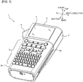
- top”, bottom, front, “rear”, and “width” of a print label producing device 1 correspond respectively to directions of arrows appropriately indicated in views of Fig. 1 , etc.
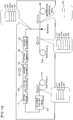
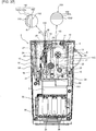
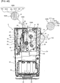
- Figs. 1 and 2 show an example of a print label producing device that is mounted with an adhesive tape cartridge of this embodiment.
- the print label producing device 1 is handheld electronic equipment grasped by a user's hand.
- the print label producing device 1 comprises a device body 2 and a cover 3 attached removably to a rear surface of the device body 2.
- the device body 2 includes a thin flat substantially rectangular parallelepiped housing 2A elongated in the top-bottom direction.
- a front surface of the housing 2A has, at its upper portion, a liquid crystal display part 4 for displaying print data, a setting screen, etc. and, below the liquid crystal display part 4, a keyboard part 5 for operating the label producing device 1.
- the keyboard part 5 has keys arranged thereon including letter keys such as letters, symbols, and numerals and various function keys.
- a side wall portion 2a on one side (left side in Fig. 1 , right side in Fig. 2 ) in the width direction of the housing 2A has at its upper portion a cut operation lever 6 for cutting a printed label tape.
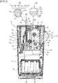
- the device body 2 comprises a label production part 10 and a battery storage part 30.
- the label production part 10 and the battery storage part 30 are comparted by a container part 8 containing a control substrate, a motor, etc. not shown.
- the battery storage part 30 has a rectangular recessed portion 32.
- a plurality of shallow concaves extending in the top-bottom direction are arranged along the width direction on a bottom 34 of the recessed portion 32.
- the same number of batteries not shown are stored in upper and lower stages within the battery storage part 30.
- the label production part 10 comprises: a recessed cartridge holder 12 for removably attaching an adhesive tape cartridge 11 (hereinafter, referred to simply as "cartridge 11"), disposed so as to occupy most of substantially the upper half of the device body 2; and a printing/feeding mechanism 13 disposed in a region including the other side (left side in Fig. 2 ) in the width direction of the cartridge holder 12.
- carrier 11 an adhesive tape cartridge 11
- the cartridge 11 is called a so-called laminated type in this embodiment and comprises, within the interior of a housing 11A as shown in Fig. 2 , an adhesive tape roll 14, a print-receiving tape roll 15, an ink ribbon roll 16, an ink ribbon take-up roller 17, and a feeding roller 18.
- the adhesive tape roll 14 is made up by winding a double-faced adhesive tape 150 around a spool 50. As shown in an enlarged view in Fig.
- the double-faced adhesive tape 150 includes: an adhesive layer 161 to which a permeable glitter pigment is added; an adhesive layer 162 to which a solid pigment is added; a colored layer 180; a film layer 151; an adhesive layer 170; and a separation material layer 152; laminated in the mentioned order from the spool 50 lying on a radial center side toward the radial outside.
- the print-receiving tape roll 15 is made up by winding a print-receiving tape 110 having a transmittance of 20% or more for example around a spool 60.
- the printing/feeding mechanism 13 comprises a support shaft 19 of the adhesive tape roll 14, a support shaft 20 of the print-receiving tape roll 15, a support shaft 21 of the ink ribbon roll 16, a driving shaft 22 of the ink ribbon take-up roller 17, a thermal head 23, a platen roller 24, a driving shaft 25 of the feeding roller 18, and a pressing roller 26.
- the platen roller 24 together with the pressing roller 26 is fitted to a roll holder 27 so that swinging of the roll holder 27 can cause switching between a printing/feeding position (position shown in Fig. 2 ) where the platen roller 24 and the pressing roller 26 are in contact with the thermal head 23 and the feeding roller 18, respectively, and a standby position not shown where the platen roller 24 and the pressing roller 26 are apart from the thermal head 23 and the feeding roller 18, respectively.
- the platen roller 24 and the pressing roller 26 are switched to the printing/feeding position.
- the platen roller 24 switched to the printing/feeding position rotates by drive of a driving shaft not shown of the device body 2 and presses the print-receiving tape 110 fed out from the print-receiving tape roll 15 and an ink ribbon not shown fed out from the ink ribbon roll 16 against the thermal head 23.
- ink of the ink ribbon is transferred onto the print-receiving tape 110 by heat reception from the thermal head 23 so that a desired print R (see Fig. 3 , etc.
- the platen roller 24 feeds the print-receiving tape 110 having the print formed thereon and the ink ribbon toward the feeding roller 18.
- the print-terminated ink ribbon is then separated from the print-receiving tape 110 and is taken up by the ink ribbon take-up roller 17.
- the pressing roller 26 switched to the printing/feeding position presses the print-formed print-receiving tape 110 fed by the platen roller 24 and the double-faced adhesive tape 150 fed out from the adhesive tape roll 14 against the feeding roller 18 rotating by drive of the driving shaft 25.
- the print-receiving tape 110 having the print R formed thereon and the double-faced adhesive tape 150 are bonded together to form a print tap3 100, while simultaneously the feeding roller 18 feeds the print tape 100 toward a label discharging exit 29 disposed on an upper end of the device body 2.
- a user manually operates a cutting operation lever 6 to activate a cutter 28 disposed in the vicinity of the label discharging exit 29, to cut the print tape 100 to form a predetermined length of print tape 100 (i.e. print label).
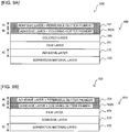
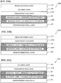
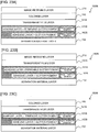
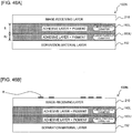
- Fig. 3 is an explanatory view showing a layered structure of the print-receiving tape 110 and the double-faced adhesive tape 150.
- the double-faced adhesive tape 150 includes: the film layer 151; the colored layer 180 disposed in contact with the film layer 151 on the upper side of the diagram; the adhesive layer 162 disposed in contact with the colored layer on the upper side of the diagram, the adhesive layer 162 having a solid pigment (details will be described later) added at a desired volume ratio (5-50 % relative to the entire adhesive layer); the adhesive layer 161 disposed in contact with the adhesive layer 162 on the upper side of the diagram, the adhesive layer 161 having a permeable glitter pigment added at a desired volume ratio (5-50 % relative to the entire adhesive layer); the adhesive layer 170 disposed in contact with the film layer 151 on the lower side of the diagram; and the separation material layer 152 disposed in contact with the adhesive layer 170 on the lower side of the diagram so as to cover the adhesive layer 170.
- this embodiment has a feature that the volume ratio (the ratio relative to the entire layer; hereinafter, the same will apply to all embodiments, background examples and modification examples) of the solid pigment in the adhesive layer 162 is greater than the volume ratio of the glitter pigment in the adhesive layer 161.
- the volume ratio of the solid pigment in the adhesive layer 162 is 1.5 times or more the volume ratio of the glitter pigment in the adhesive layer 161.
- the volume ratio can be calculated by the following procedure for example.
- a glitter pigment containing adhesive having a measured volume and weight is dissolved in a solvent so that the glitter pigment is separated by centrifugation to determine the weight of the glitter pigment and measure the true specific gravity of the glitter pigment particles to determine the volume of the glitter pigment.
- the volume of the adhesive can be determined.
- the area and the ratio of the pigment existing on the cross section can be determined and, by continuously increasing the cross section to be measured, conversion to volume becomes possible so that the volume ratio can be determined (hereinafter, the same will apply to the modification examples, background examples and other embodiments described later).
- a thickness tA of the glitter pigment containing adhesive layer 161 is smaller than a thickness tC of the adhesive layer 170; a thickness tB of the solid pigment containing adhesive layer 162 is smaller than the thickness tC of the adhesive layer 170; and the sum of the thickness tA of the adhesive layer 161 and the thickness tB of the adhesive layer 162 is greater than the thickness tC of the adhesive layer 170.
- the glitter pigment contained in the adhesive layer 161 has a transmittance of 20 % or more.
- the print-receiving tape 110 has the print R as described above on a surface on the side (lower side of the diagram; the other side in the thickness direction in this embodiment) facing the double-faced adhesive tape 150.
- the print-receiving tape 110 is bonded via the adhesive layer 161 to the double-faced adhesive tape 150.
- Fig. 4A shows a layered structure of the print tape 100 formed by bonding the print-receiving tape 110 and the double-faced adhesive tape 150 together
- Fig. 4B shows a state where the print tape 100 is adhered via the adhesive layer 170 to an adherend M with the separation material layer 152 being separated from the print tape 100.
- the print tape 100 is made up by laminating, from the upper side of the diagram toward the lower side thereof, the print-receiving tape 110, the adhesive layer 161 (to which the permeable glitter pigment is added), the adhesive layer 162 (to which the solid pigment is added), the colored layer 180, the film layer 151, the adhesive layer 170, and the separation material layer 152, in the mentioned order.
- the configuration may be such that the adhesive layer 162 is disposed in contact with the film layer 151 on the upper side of the diagram, without interposing the colored layer 180 between the adhesive layer 162 and film layer 151.
- Fig. 5B shows a state where the print tape 100 produced as above using the double-faced adhesive tape 150 of such a configuration is adhered via the adhesive layer 170 to the adherend M, with the separation material layer 152 being separated from the print tape 100.
- the separation material layer 152 is formed by coating a base material with a separation material for example.
- the base material can be paper, PET film, OPP film, polyethylene film, etc.
- the separation material can be silicone resin, polyethylene resin, etc.
- the adhesives of the adhesive layer 161, the adhesive layer 162, and the adhesive layer 170 can be for example urethane resin-based, silicone resin-based, vinyl resin-based, polyester resin-based, synthetic rubber-based, natural rubber-based, and acrylic resin-based adhesives.
- the solid pigment added to the adhesive layer 162 can be inorganic pigments such as oxides and organic pigments such as a textile printing-based pigment.
- the inorganic pigments can be for example: oxides such as titanium dioxide and zinc oxide; hydroxides such as alumina white and iron oxide yellow; sulfides such as zinc sulfide and lithopone; chrome oxides such as chrome yellow and molybdate orange; silicates such as white carbon and clay; sulfates such as precipitated barium sulfate and baryta powder; carbonates such as calcium carbonate and lead white; and others such as ferrocyanides (Prussian blue) and carbon (carbon black).
- oxides such as titanium dioxide and zinc oxide
- hydroxides such as alumina white and iron oxide yellow
- sulfides such as zinc sulfide and lithopone
- chrome oxides such as chrome yellow and molybdate orange
- silicates such as white carbon and clay
- sulfates such as precipitated barium s
- the organic pigments can be for example: textile printing-based pigments including basic dyes such as rhodamine lake and methyl violet lake, acidic dyes such as quinoline yellow lake, vat dyes such as malachite green, and mordant dyes such as alizarin lake; azo pigments including soluble azo such as carmine 6B, insoluble azo such as disazoyellow, condensed azo such as cromophtal yellow, azo complex salts such as nickel azo yellow, and benzimidazolone azo such as permanent orange HL; phthalocyanine pigments such as phthalocyanine blue; condensed polycyclic pigments such as flavanthrone yellow; nitro-based pigments such as naphthol yellow S; nitroso-based pigments such as pigment green B; day and night fluorescent pigments such as lumogen yellow; and others such as alkali blue.
- basic dyes such as rhodamine lake and methyl violet lake
- acidic dyes such as
- the permeable glitter pigment added to the adhesive layer 161 can be ones coating the surface of a core material such as scaly mica, glass, alumina, and metal with a colorant such as titanium oxide and iron oxide or with the solid pigment as the colorant. Some tinges of the glitter pigment may allow use of ones creating a color by interference of reflected light from the core material without coating the core material with the colorant.
- the glitter pigment is a collective designation of pigments having the brilliance described above and is known for example as a pearl pigment, a metallic pigment, etc.
- the above materials of the separation material layer 152 and the above materials/components of the separation agent, the adhesive, the solid pigment, and the glitter pigment can be used commonly for modification examples, background examples and other embodiments that will be described later.
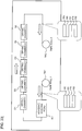
- a manufacturing process of the double-faced adhesive tape 150 will next be described with reference to Figs. 6 to 8 .
- the film layer 151 having the colored layer 180 formed thereon by a known printing technique for example is fed out from a film roll FR and is supplied to an adhesive coating head AH.
- an adhesive of the above composition is applied to a surface of the film layer 151 opposite to the colored layer 180, to obtain a three-layered structure including the colored layer 180, the film layer 151, and the adhesive layer 170, after which the structure passes through a first drying chamber D1, a second drying chamber D2, a third drying chamber D3, a fourth drying chamber D4, and a fifth drying chamber D5, in the mentioned order, to undergo a five-stage drying process.
- the number of the drying chambers is not limited to five.
- the separation material layer 152 fed out separately from a separation material roll SR is bonded to the adhesive layer 170 so that the tape of the three-layered structure turns into a tape of a four-layered structure, which is wound onto a first tape roll TR1.
- the tape of the four-layered structure including the colored layer 180, the film layer 151, the adhesive layer 170, and the separation material layer 152 is fed out from the first tape roll TR1 and is supplied to the adhesive coating head AH in the same manner as the above.
- an adhesive (containing the solid pigment) of the above composition is applied to a surface of the colored layer 180 opposite to the film layer 151, to obtain a five-layered structure including the adhesive layer 162 (having the solid pigment added), the colored layer 180, the film layer 151, the adhesive layer 170, and the separation material layer 152, after which similarly to the above, the structure passes through the first to fifth drying chambers D1 to D5, in the mentioned order, to undergo the drying process and is wound onto a second tape roll TR2.
- the tape of the five-layered structure including the adhesive layer 162, the colored layer 180, the film layer 151, the adhesive layer 170, and the separation material layer 152 is fed out from the second tape roll R2 and is supplied to the adhesive coating head AH in the same manner as the above.
- an adhesive (containing the permeable glitter pigment) of the above composition is applied to a surface of the adhesive layer 162 opposite to the colored layer 180, to obtain a six-layered structure including the adhesive layer 161 (having the permeable glitter pigment added), the adhesive layer 162, the colored layer 180, the film layer 151, the adhesive layer 170, and the separation material layer 152, after which similarly to the above, the structure passes through the first to fifth drying chambers D1 to D5, in the mentioned order, to undergo the drying process to complete the double-faced adhesive tape 150.
- the thus completed double-faced adhesive tape 150 is wound onto a third tape roll TR3.
- Figs. 6 to 8 the case has been described by way of example where the adhesive coating head AH is disposed only at a single location, another adhesive coating head AH may separately be disposed downstream of the drying chamber D5 along the transport path. In this case, intactly after the coating process of the adhesive layer 162 and the drying process through the drying chambers D1 to D5 in Fig. 7 , the coating process of the adhesive layer 161 (described using Fig. 8 ) can be performed.
- the pigment permeable glitter pigment in this example
- the pigment solid pigment in this example
- a pigment permeable glitter pigment
- another adhesive layer 162 with a pigment solid pigment
- the permeable glitter pigment lies closer than the solid pigment when viewed from one side in the thickness direction (the upper side in Figs. 3 to 5 ), there can be obtained an effect that glitter particles especially look three-dimensional.
- the adhesive layer 161 originally arranged for bonding to contain one (permeable glitter pigment) of the two pigments, the number of layers increased from the above four layers is only one, so that the increase in the total thickness of the double-faced adhesive tape 150 and in the number of manufacturing steps can be suppressed. As a result, regardless of a limited space, the tape length capable of being wound onto the adhesive tape roll 14 can be extended.
- two different colors can be represented by a single tape, while suppressing the increase in the total thickness of the double-faced adhesive tape 150 and in the number of manufacturing steps thereof.
- the configuration is such that when the newly disposed layer is the adhesive layer 162, respective pigments are added to the two adhesive layers 161 and 162.
- this adhesive layer 162 has less restriction from the bonding performance needed for the double-faced adhesive tape 150 (see the adhesion in a manufacturing facility described later), thus enabling a greater amount of solid pigment to be added. Since the bonding performance required for the double-faced adhesive tape 150 may be satisfied by the combination of the adhesive layer 162 and the adhesive layer 161, the restriction from the bonding performance in the adhesive layer 161 can also become less than the case of the four-layered structure described above.
- the adhesive layer 162 disposed on one side in the thickness direction of the film layer 151 (having the colored layer 180 formed thereon) is bonded to the colored layer 180 at the time of manufacturing in the state shown in Figs. 6 to 8 for example where the adhesive layer 162 is managed in the factory manufacturing facility.
- the adhesive layer 161 is bonded to the print-receiving tape 110 within the print label producing device 1 at the time of printing as described above. For this reason, the bonding force of the adhesive layer 161 needs to be greater than that of the adhesive layer 162.
- This first embodiment can meet the above requirement by setting the volume ratio of the pigment in the adhesive layer 161 to be less than that of the pigment in the adhesive layer 162 as described above.
- the volume ratio of the solid pigment in the adhesive layer 162 is 1.5 times or more the volume ratio of the glitter pigment in the adhesive layer 161. This has the following significance.
- a large amount of second pigment cannot be added due to the adhesive surface (to secure a bonding force of 3 N/10 mm).
- a large amount of first pigment can be added due to less restriction from the bonding force, and the addition of 1.5 times or more can enhance the chroma and glitter feeling.
- the sum of the thickness tA of the adhesive layer 161 and the thickness tB of the adhesive layer 162 is greater than the thickness tC of the adhesive layer 170.
- the permeable glitter pigment of the adhesive layer 161 has a transmittance of 20 % or more. This ensures a reliable visual recognition of the color of the solid pigment of the adhesive layer 162 on the far side when viewed from one side (upper side in Figs. 3 to 5 ) in the thickness direction (see a broken line arrow a of Fig. 4B ). Since the permeable glitter pigment having permeability is added to a layer separate from the solid pigment, the glitter feeling from the glitter pigment of the adhesive layer 161 can be restrained from being disappeared by the solid pigment of the adhesive layer 162.
- the first embodiment is not limited to the above mode and can variously be modified. Modification examples thereof will hereinafter be described in order. Parts similar to those of the first embodiment are designated by the same reference numerals and explanations thereof will appropriately be omitted or simplified.
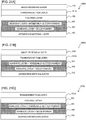
- the adhesive layer 162 with the solid pigment added may be replaced by an adhesive layer 162A with a coloring glitter pigment added. Similar to the adhesive layer 162, the coloring glitter pigment is added at a volume ratio of 5-50 % for example to the adhesive layer 162A.
- the colored layer 180 may be removed. This case also presents an advantage similar to the above.
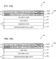
- the adhesive layer 162 with the solid pigment added may be replaced by an adhesive layer 162B with a glitter pigment added.
- the average particle diameter of a permeable glitter pigment in an adhesive layer 161B (containing the permeable glitter pigment similar to that in the adhesive layer 161) is greater than the average particle diameter of the glitter pigment in the adhesive layer 162B.
- the average particle diameter of the glitter pigment in the adhesive layer 162B is less than 30 ⁇ m, whereas the average particle diameter of the permeable glitter pigment in the adhesive layer 161B is not less than 40 ⁇ m.
- the average particle diameter is measured by the known laser diffraction scattering method. For example, it can be measured by LA-960 manufactured by Horiba, Ltd. (hereafter, the same will apply to modification examples, background examples and other embodiments described later).
- the glitter pigment and the permeable glitter pigment are of similar colors to each other and are made of the same material.
- the glitter pigment is added at a volume ratio of 5-50 % for example to the adhesive layer 162B similarly to the adhesive layer 162, whereas the permeable glitter pigment is added at a volume ratio of 5-50 % for example to the adhesive layer 161B similarly to the adhesive layer 161.
- the volume ratio of the glitter pigment in the adhesive layer 162B is greater than the volume ratio of the glitter pigment in the adhesive layer 161B.
- the volume ratio of the glitter pigment in the adhesive layer 162B is 1.5 times or more the volume ratio of the glitter pigment in the adhesive layer 161B.
- the thickness tA of the adhesive layer 161B containing the permeable glitter pigment is smaller than the thickness tC of the adhesive layer 170 while the thickness tB of the adhesive layer 162B containing the glitter pigment is smaller than the thickness tC of the adhesive layer 170, the sum of the thickness tA of the adhesive layer 161B and the thickness tB of the adhesive layer 162B being greater than the thickness tC of the adhesive layer 170.
- the permeable glitter pigment contained in the adhesive layer 161B has a transmittance of 20 % or more.
- the colored layer 180 may be removed from the structure shown in Fig. 10A .
- This modification example also presents an advantage similar to that of the first embodiment.
- the average particle diameter of the glitter pigment in the adhesive layer 162B is smaller than the average particle diameter of the permeable glitter pigment in the adhesive layer 161B.
- the average particle diameter of the glitter pigment in the adhesive layer 162B is less than 30 ⁇ m and the average particle diameter of the permeable glitter pigment in the adhesive layer 161B is greater than or equal to 40 ⁇ m.
- the particle diameter of 40 ⁇ m or more ensures visual confirmation of particle feeling, and therefore the overlying arrangement cannot impair the particle feeling as compared with the underlying arrangement.
- the particle feeling becomes more noticeable (60 ⁇ m or more is even better).
- the overlying particle feeling can hardly be impaired.
- the overlying particle feeling can be less impaired (10 ⁇ m or less is even better).
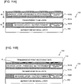
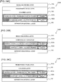
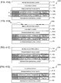
- FIG. 11A A layered structure of the double-faced adhesive tape according to the first background example is shown in Fig. 11A corresponding to Fig. 3 .
- the double-faced adhesive tape 150 of this first background example has a transparent film layer 151A that is transparent (or translucent is acceptable; the same will apply to all below) instead of the film layer 151 in the layered structure shown in Fig. 10B .
- the adhesive layer 162B (to which the glitter pigment is added) disposed on the upper side of the film layer 151 in Fig. 10B is disposed on the lower side of the transparent film layer 151A in Fig. 11 , with a resultant removal of the adhesive layer 170.
- the thickness magnitude relationship of the adhesive layer 161B will be described later.
- the double-faced adhesive tape 150 of this background example includes: the transparent film layer 151A; the adhesive layer 161B disposed in contact with the transparent film layer 151A on the upper side in Fig. 11A and having the permeable glitter pigment added at a desired volume ratio (5-50 % relative to the entire adhesive layer); the adhesive layer 162B disposed in contact with the transparent film layer 151A on the lower side of the diagram and having the glitter pigment added at a desired volume ratio (5-50 % relative to the entire adhesive layer); and the separation material layer 152 disposed in contact with the adhesive layer 162B on the lower side of the diagram and covering the adhesive layer 162B.
- this background example has a feature that the thickness tA of the adhesive layer 161B containing the permeable glitter pigment is greater than the thickness tC of the adhesive layer 162B containing the glitter pigment.
- the volume ratio of the glitter pigment in the adhesive layer 162B is smaller than the volume ratio of the permeable glitter pigment in the adhesive layer 161B. Specifically, the volume ratio of the permeable glitter pigment in the adhesive layer 161B is 1.5 times or more the volume ratio of the glitter pigment in the adhesive layer 162B.
- the volume ratio can be measured by the technique similar to that of the first embodiment for example.
- the permeable glitter pigment contained in the adhesive layer 161B has a transmittance of 20 % or more.
- the average particle diameter of the permeable glitter pigment in the adhesive layer 161B containing the permeable glitter pigment differs from the average particle diameter of the glitter pigment in the adhesive layer 162B.
- the average particle diameter of the permeable glitter pigment in the adhesive layer 161B is greater than the average particle diameter of the glitter pigment in the adhesive layer 162B.
- the average particle diameter of the glitter pigment in the adhesive layer 162B is less than 30 ⁇ m, whereas the average particle diameter of the permeable glitter pigment in the adhesive layer 161B is greater than or equal to 40 ⁇ m.
- the average particle diameter can be measured by the technique similar to that in the first embodiment for example.
- the permeable glitter pigment in the adhesive layer 161B and the glitter pigment in the adhesive layer 162B are of similar colors to each other and are made of the same material.
- the double-faced adhesive tape 150 of this first background example is also wound onto the adhesive tape roll 14 and is arranged, together with the ink ribbon roll 16, within the housing 11A of the cartridge 11.
- Fig. 11B shows a layered structure of the print tape 100 formed by bonding together the print-receiving tape 110 and the double-faced adhesive tape 150 shown in Fig. 11A .
- the print tape 100 includes, from the upper side of the diagram toward the lower side thereof, the print-receiving tape 110, the adhesive layer 161B (to which the permeable glitter pigment is added), the transparent film layer 151A, the adhesive layer 162B (to which the glitter pigment is added), and the separation material layer 152, laminated in the mentioned order.
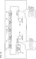
- a manufacturing process of the double-faced adhesive tape 150 will next be described with reference to Figs. 12 and 13 .
- the transparent film layer 151A is fed out from the film roll FR and is supplied to the adhesive coating head AH.
- an adhesive (containing the glitter pigment) of the above composition is applied to a surface of the transparent film layer 151A, to obtain a two-layered structure including the transparent film layer 151A and the adhesive layer 162B (to which the glitter pigment is added), after which the structure passes through the first drying chamber D1, the second drying chamber D2, the third drying chamber D3, the fourth drying chamber D4, and the fifth drying chamber D5, in the mentioned order, to undergo a five-stage drying process.
- the number of the drying chambers is not limited to five.
- the separation material layer 152 separately fed out from the separation material roll SR is bonded to the adhesive layer 162B so that the tape of the two-layered structure turns to a tape of a three-layered structure including the transparent film layer 151A, the adhesive layer 162B, and the separation material layer 152, after which it is wound onto the first tape roll TR1.
- the tape of the three-layered structure of the transparent film layer 151A, the adhesive layer 162B, and the separation material layer 152 is fed out from the first tape roll R1 and is supplied to the adhesive coating head AH in the same manner as the above.
- an adhesive (containing the permeable glitter pigment) of the above composition is applied to a surface of the transparent film layer 151A opposite to the adhesive layer 162B, to obtain a four-layered structure including the adhesive layer 161B (to which the permeable glitter pigment is added), the transparent film layer 151B, the adhesive layer 162B, and the separation material layer 152, after which similarly to the above, the structure passes through the first to fifth drying chambers D1 to D5, in the mentioned order, to undergo the drying process to bring the double-faced adhesive tape 150 to completion. The thus completed double-faced adhesive tape 150 is wound onto the second tape roll TR2.
- Figs. 12 and 13 the case has been described by way of example where the adhesive coating head AH is disposed only at a single location, another adhesive coating head AH may separately be disposed downstream of the drying chamber D5 along the transport path.
- This first background example can also present an advantage similar to that of the first embodiment and the modification examples.
- the pigment permeable glitter pigment in this example
- the pigment is added to the bonding adhesive layer 161B
- the pigment glitter pigment in this example
- respective pigments are arranged in the two adhesive layers 161B and 162B, respectively, with the transparent film layer 151A being a film layer interposed therebetween.
- the transparent film layer 151A being a film layer interposed therebetween.
- two different colors can be represented by a single tape, while suppressing the increase in the total thickness of the double-faced adhesive tape 150 and in the number of manufacturing steps thereof.
- the glitter pigment and the permeable glitter pigment having average particle diameters different from each other separately into two layers there can be obtained both a uniform moisture feeling induced by the glitter pigment with a small average particle diameter and a glaring granular feeling induced by the permeable glitter pigment with a large average particle diameter, so that a unique brilliant tape can be produced.
- the glitter pigment with a small average particle diameter is located on the far side while the permeable glitter pigment with a large average particle diameter is located on the near side when viewed from one side (upper side in Fig. 11 ) in the thickness direction, a high brilliance and depth can be obtained.
- the average particle diameter of the glitter pigment in the adhesive layer 162B is less than 30 ⁇ m and the average particle diameter of the permeable glitter pigment in the adhesive layer 161B is greater than or equal to 40 ⁇ m.
- the particle diameter of 40 ⁇ m or more ensures visual confirmation of particle feeling, and therefore the overlying arrangement cannot impair the particle feeling as compared with the underlying arrangement.
- the particle feeling becomes more noticeable (60 ⁇ m or more is even better).
- the overlying particle feeling can hardly be impaired.
- the overlying particle feeling can be less impaired (10 ⁇ m or less is even better).
- the permeable glitter pigment of the adhesive layer 161B has a transmittance of 20 % or more. This ensures a reliable visual recognition of the color of the glitter pigment of the adhesive layer 162B on the far side when viewed from one side (upper side in Fig. 11 ) in the thickness direction. Since the permeable glitter pigment having permeability is added to a layer separate from the glitter pigment, the glitter feeling from the glitter pigment of the adhesive layer 161B can be restrained from being disappeared by the glitter pigment of the adhesive layer 162B.
- the volume ratio of the permeable glitter pigment in the adhesive layer 161B is 1.5 times or more the volume ratio of the glitter pigment in the adhesive layer 162B. This has the following significance.
- a large amount of second pigment cannot be added due to the adhesive surface (to secure the bonding force of 3 N/10 mm).
- a large amount of first pigment can be added due to less restriction from the bonding force and the addition of 1.5 times or more can enhance the chroma and glitter feeling.
- the transparent film layer 151A may be removed.
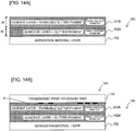
- a modification example is shown in Fig. 14A .
- the same reference numerals are imparted to parts equivalent to those in the first embodiment and the first background example and their modification examples, and explanations thereof will appropriately be omitted or simplified.
- the double-faced adhesive tape 150 includes, from the upper side toward the lower side of the diagram, the adhesive layer 161B (to which the permeable glitter pigment is added), the adhesive layer 162B (to which the glitter pigment is added), and the separation material layer 152, laminated in the mentioned order.
- Fig. 14B shows a layered structure of the print tape 100 formed by bonding the print-receiving tape 110 and the double-faced adhesive tape 150 shown in Fig. 14A together.
- the print tape 100 includes, from the upper side toward the lower side of the diagram, the print-receiving tape 110, the adhesive layer 161B (to which the permeable glitter pigment is added), the adhesive layer 162B (to which the glitter pigment is added), and the separation material layer 152, laminated in the mentioned order.
- This modification example also presents an advantage similar to that of the first background example.
- a second background example of the present invention will be described with reference to Figs. 15 to 24 .
- this background example is an example using a cartridge called a so-called non-laminated type (in more detail, receptor type).
- Parts equivalent to those of the first embodiment, the first background example, and the modification examples thereof are designated by the same reference numerals, and explanations thereof will appropriately be omitted or simplified.
- Fig. 15 illustrates a plan view corresponding to Fig. 2 of the first embodiment and showing a rear internal structure of a device body of a print label producing device in the second background example.
- the cartridge 11 for use in this background example comprises, within the interior of the housing 11A, the adhesive tape roll 14 (detailed layered structure will be described later), the ink ribbon roll 16, the ink ribbon take-up roller 17, and the feeding roller 18.
- the adhesive tape roll 14 is made up by winding an adhesive tape 150N in relation to this background example around the spool 50.
- the adhesive tape 150N includes: an image receiving layer 210; the colored layer 180 similar to the above; the transparent film layer 151A that is transparent (or translucent is acceptable; the same applies hereinafter) similar to the above, the adhesive layer 161 to which the permeable glitter pigment is added similar to the above, the adhesive layer 162 to which the solid pigment is added similar to the above, and the separation material layer 152, laminated in the mentioned order from the spool 50 lying on the radial center side (corresponding to the upper side in Fig. 16 described later) toward the radial outside (corresponding to the lower side in Fig. 16 described later).
- the platen roller 24 presses the adhesive tape 150N fed out from the adhesive tape roll 14 and an ink ribbon not shown fed out from the ink ribbon roll 16 against the thermal head 23.
- ink of the ink ribbon is transferred onto the image receiving layer 210 of the adhesive tape 150N by heat reception from the thermal head 23 so that a desired print R (see Fig. 3 , etc. described later) is formed on the adhesive tape 150N to obtain a print tape 100N so that the platen roller 24 feeds the print tape 100N having the print formed thereon and the ink ribbon toward the feeding roller 18.
- the feeding roller 18 further feeds the print tape 100N toward the label discharging exit 29 disposed on the upper end of the device body 2.
- the user manually operates the cutting operation lever 6 to activate the cutter 28 disposed in the vicinity of the label discharging exit 29, to cut the print tape 100N into a predetermined length of print tape 100N (i.e. print label).
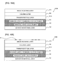
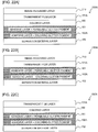
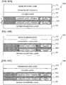
- Fig. 16 is an explanatory view showing layered structures of the adhesive tape 150N and the print tape 100N corresponding to Figs. 3 and 4 of the first embodiment.
- the adhesive tape 150N includes: the transparent film layer 151A; the colored layer 180 disposed in contact with the transparent film layer 151A on the upper side of the diagram; the image receiving layer 210 disposed in contact with the colored layer 180 on the upper side of the diagram; the adhesive layer 161 disposed in contact with the transparent film layer 151A on the lower side of the diagram, the adhesive layer 161 having the permeable glitter pigment added at a desired volume ratio (5-50 % relative to the entire adhesive layer); the adhesive layer 162 disposed in contact with the adhesive layer 161 on the lower side of the diagram, the adhesive layer 162 having the solid pigment added at a desired volume ratio (5-50 % relative to the entire adhesive layer); and the separation material layer 152 disposed in contact with the adhesive layer 162 on the lower side of the diagram so as to cover the adhesive layer 162.
- this background example has a feature that the volume ratio of the solid pigment in the adhesive layer 162 is smaller than the volume ratio of the permeable glitter pigment in the adhesive layer 161.
- the volume ratio of the permeable glitter pigment in the adhesive layer 161 is 1.5 times or more the volume ratio of the solid pigment in the adhesive layer 162.
- the volume ratio can be measured by the technique similar to that in the first embodiment for example.
- the solid pigment in the adhesive layer 162 and the permeable glitter pigment in the adhesive layer 161 are made of the same material.
- the permeable glitter pigment contained in the adhesive layer 161 has a transmittance of 20 % or more.
- the image receiving layer 210 also has a transmittance of 20 % or more.
- Fig. 16B shows a layered structure of the print tape 100N in which print R is formed on the image receiving layer 210 of the adhesive tape 150N.
- a manufacturing process of the adhesive tape 150N will next be described with reference to Figs. 17 and 18 .
- the transparent film layer 151A having the image receiving layer 210 and the colored layer 180 formed thereon by the known printing technique for example is fed out from the film roll FR and is supplied to the adhesive coating head AH.
- an adhesive (containing the permeable glitter pigment) of the above composition is applied to a surface of the transparent film layer 151A opposite to the colored layer 180, to obtain a four-layered structure including the image receiving layer 210, the colored layer 180, the transparent film layer 151A, and the adhesive layer 161 (to which the permeable glitter pigment is added), after which the structure passes through the first drying chamber D1, the second drying chamber D2, the third drying chamber D3, the fourth drying chamber D4, and the fifth drying chamber D5, in the mentioned order to undergo the five-stage drying process and is wound onto the first tape roll TR1.
- the number of the drying chambers is not limited to five.
- the tape of the four-layered structure including the image receiving layer 210, the colored layer 180, the transparent film layer 151A, and the adhesive layer 161 is fed out from the first tape roll TR1 and is supplied to the adhesive coating head AH in the same manner as the above.
- an adhesive (containing the solid pigment) of the above composition is applied to a surface of the adhesive layer 161 opposite to the film layer 151A, to obtain a five-layered structure including the image receiving layer 210, the colored layer 180, the transparent film layer 151A, the adhesive layer 161, and the adhesive layer 162 (to which the solid pigment is added), after which similarly to the above, the structure passes through the first to fifth drying chambers D1 to D5, in the mentioned order, to undergo the drying process.
- the separation material layer 152 separately fed out from the separation material roll SR is bonded to the adhesive layer 162 so that the tape of the five-layered structure is completed as the adhesive tape 150N of a six-layered structure including the image receiving layer 210, the colored layer 180, the transparent film layer 151A, the adhesive layer 161, the adhesive layer 162, and the separation material layer 152.
- the thus completed adhesive tape 150N is wound onto the second tape roll TR2.
- Figs. 17 and 18 the case has been described by way of example where the adhesive coating head AH is disposed only at a single location, another adhesive coating head AH may separately be disposed downstream of the drying chamber D5 along the transport path.
- the coating process of the adhesive layer 162 and the bonding process of the separation material layer 152 can be performed.
- the configuration may be such that the image receiving layer 210 is disposed in contact with the transparent film layer 151A on the upper side of the diagram, without interposing the colored layer 180 between the image receiving layer 210 and the transparent film layer 151A.
- the colored layer 180 may be disposed in contact with the transparent film layer 151A on the upper side of the diagram, without disposing the image receiving layer 210.
- This second background example can also present an advantage similar to that of the first and the first background examples and the modification examples. If desired to use two different pigments with the intention of obtaining two different colors for example in the adhesive tape, intermixture of those pigments within a single layer brings about interference between the two pigments, hindering the pigments from fully exerting their respective effects.
- a pigment permeable glitter pigment
- another adhesive layer 162 with a pigment solid pigment
- the permeable glitter pigment lies closer than the solid pigment when viewed from the other side (upper side in Figs. 16 and 11 ) in the thickness direction, there can be obtained an advantage that glitter particles especially look three-dimensional.
- the number of layers of the entire tape is limited to six, so that the increase in the total thickness of the adhesive tape 150N and in the number of manufacturing steps can be suppressed. As a result, regardless of a limited space, the tape length capable of being wound onto the adhesive tape roll 14 can be extended.
- the volume ratio of the solid pigment in the adhesive layer 162 is set to be less than the volume ratio of the permeable glitter pigment in the adhesive layer 161. This has the following significance. Although in general, the more a pigment is added to an adhesive layer, the lower the bonding performance becomes, the adhesive layer 161 has less restriction from the bonding performance required for the adhesive tape (due to no exposure to the surface), thereby allowing a larger amount of permeable glitter pigment to be added. On the contrary, the volume ratio of the solid pigment in the adhesive layer 162 is reduced so that the bonding force to the adherend can be secured.
- the adhesive layer 161 disposed on one side in the thickness direction of the transparent film layer 151A is bonded to the transparent film layer 151A while being managed in the factory manufacturing facility for example at the time of manufacturing as described above using Figs. 17 and 18 .
- the adhesive layer 162 needs to have a bonding force greater than that of the adhesive layer 161 because the adherend has not yet been determined and because the adhesion is made by the user.
- This second background example can deal with the above by setting the volume ratio of the solid pigment in the adhesive layer 162 to be less than the volume ratio of the permeable glitter pigment in the adhesive layer 161.
- the permeable glitter pigment of the adhesive layer 161 has a transmittance of 20 % or more. This ensures a reliable visual recognition of the color of the solid pigment of the adhesive layer 162 on the far side when viewed from the other side (upper side in Fig. 16 and 19 ) in the thickness direction. Since the permeable glitter pigment having permeability is added to a layer separate from the solid pigment, the glitter feeling from the permeable glitter pigment of the adhesive layer 161 can be restrained from being disappeared by the solid pigment of the adhesive layer 162.
- the volume ratio of the permeable glitter pigment in the adhesive layer 161 is 1.5 times or more the volume ratio of the solid pigment in the adhesive layer 162.
- a large amount of second pigment cannot be added due to the adhesive surface (to secure the bonding force of 3 N/10 mm).
- a large amount of first pigment can be added due to less restriction from the bonding force, and the addition of 1.5 times or more can enhance the chroma and glitter feeling.
- the second background example is not limited to the above mode and can variously be modified. Modification examples thereof will hereinafter be described in order. Parts similar to those of the first embodiment, first and second background examples and modification examples thereof are designated by the same reference numerals and explanations thereof will appropriately be omitted or simplified.
- the adhesive layer 162 with the solid pigment added may be replaced by the adhesive layer 162A with the coloring glitter pigment added.
- the coloring glitter pigment is added at a volume ratio of 5-50 % for example relative to the entire adhesive layer.
- the colored layer 180 may be removed.
- the image receiving layer 210 may be removed.
- the transparent film layer 151A and the colored layer 180 may be interchanged so that the image receiving layer 210, the transparent film layer 151A, the colored layer 180, the adhesive layer 161, the adhesive layer 162, and the separation material layer 152 are laminated in the mentioned order from the upper side toward the lower side of the diagram.
- the colored layer 180 may be removed from the layered structure of the adhesive tape 150N shown in Fig. 21A (in this case, the same layered structure as in Fig. 19A results).
- the image receiving layer 210 may be removed from the layered structure of the adhesive tape 150N shown in Fig. 21A .
- the adhesive layer 162 with the solid pigment added may be replaced by the adhesive layer 162A with the coloring glitter pigment added.
- the coloring glitter pigment is added at a volume ratio of 5-50 % for example relative to the entire adhesive layer.
- the colored layer 180 may be removed from the layered structure of the adhesive tape 150N shown in Fig. 22A (in this case, the same layered structure as in Fig. 20B results).
- the image receiving layer 210 may be removed from the layered structure of the adhesive tape 150N shown in Fig. 22A .
- the adhesive layer 162 with the solid pigment added may be replaced by the adhesive layer 162B with the glitter pigment added.
- the average particle diameter of the permeable glitter pigment in the adhesive layer 161B (containing the permeable glitter pigment similar to that in the adhesive layer 161) is greater than the average particle diameter of the glitter pigment in the adhesive layer 162B.
- the average particle diameter of the glitter pigment in the adhesive layer 162B is less than 30 ⁇ m, whereas the average particle diameter of the permeable glitter pigment in the adhesive layer 161B is not less than 40 ⁇ m.
- the average particle diameter can be measured by a technique similar to that of the first embodiment for example.
- the particle diameter of 40 ⁇ m or more ensures visual confirmation of particle feeling, and therefore the overlying arrangement cannot impair the particle feeling as compared with the underlying arrangement.
- the particle feeling becomes more noticeable (60 ⁇ m or more is even better).
- the overlying particle feeling can hardly be impaired.
- the overlying particle feeling can be less impaired (10 ⁇ m or less is even better).
- the glitter pigment is added to the adhesive layer 162B in a volume ratio of 5-50 % for example relative to the entire adhesive layer in the same manner as the adhesive layer 162, whereas the permeable glitter pigment is added to the adhesive layer 161B in a volume ratio of 5-50 % for example relative to the entire adhesive layer in the same manner as the adhesive layer 161.
- the permeable glitter pigment contained in the adhesive layer 161B has a transmittance of 20 % or more.
- the colored layer 180 may be removed from the structure shown in Fig. 23A .
- the image receiving layer 210 may be removed from the structure shown in Fig. 23A .
- This modification example also presents an advantage similar to that of the second background example.
- the average particle diameter of the glitter pigment in the adhesive layer 162B is smaller than the average particle diameter of the permeable glitter pigment in the adhesive layer 161B.
- the average particle diameter of the glitter pigment in the adhesive layer 162B is less than 30 ⁇ m and the average particle diameter of the permeable glitter pigment in the adhesive layer 161B is greater than or equal to 40 ⁇ m.
- the transparent film layer 151A and the colored layer 180 may be interchanged so that the image receiving layer 210, the transparent film layer 151A, the colored layer 180, the adhesive layer 161A, the adhesive layer 162A, and the separation material layer 152 are laminated in the mentioned order from the upper side (the other side in the thickness direction in the second background example and the modification examples) toward the lower side (one side in the thickness direction in the second background example and the modification examples) of the diagram.
- the colored layer 180 may be removed from the layered structure of the adhesive tape 150N shown in Fig.
- the image receiving layer 210 may be removed from the layered structure of the adhesive tape 150N shown in Fig. 24A .
- the transparent film layer 151A may be removed from the structure shown in Figs. 15 to 24 . At that time, the structure without the film layer may be expanded to the laminated type.
- Such modification examples will be described with reference to Figs. 25 to 27 .
- the same reference numerals are imparted to parts equivalent to those of the first embodiment and the first and second background examples and modification examples thereof, and explanations thereof will appropriately be omitted or simplified.
- Fig. 25 illustrates a plan view, corresponding to Fig. 2 of the first embodiment and showing a rear internal structure of a device body of a print label producing device in this modification example.
- the double-faced adhesive tape 150 wound onto the adhesive tape roll 14 disposed in the housing 11A of the cartridge 11 of this background example is configured to include: as shown in an enlarged view of Fig.
- the adhesive layer 161 with a predetermined pigment in this example, the permeable glitter pigment as the first pigment
- the adhesive layer 162 with the same or different type of particles as in the adhesive layer 161 in this example, the solid pigment as the second pigment; the same applies hereinafter
- the separation material layer 152 laminated in the mentioned order from the spool 50 lying on the radial center side (corresponding to the upper side in Fig. 26 described later) toward the radial outside (corresponding to the lower side in Fig. 27 described layer). Similar to the above, as shown in Fig.
- the print-receiving tape roll 15 is made up by winding the print-receiving tape 110 having a transmittance of 20 % or more for example around the spool 60.
- the housing 11A comprises the ink ribbon roll 16 similar to the above.
- Fig. 26 is an explanatory view showing a layered structure of the print-receiving tape 110 and the double-faced adhesive tape 150.
- the double-faced adhesive tape 150 includes: the adhesive layer 161 having the permeable glitter pigment added at a desired volume ratio (e.g. 5-50 % relative to the entire adhesive layer); the adhesive layer 162 disposed in contact with the adhesive layer 161 on the lower side of the diagram and having the solid pigment added at a desired volume ratio (e.g. 5-50 % relative to the entire adhesive layer); and the separation material layer 152 disposed in contact with the adhesive layer 162 on the lower side of the diagram so as to cover the adhesive layer 162.
- a desired volume ratio e.g. 5-50 % relative to the entire adhesive layer
- the adhesive layer 162 disposed in contact with the adhesive layer 161 on the lower side of the diagram and having the solid pigment added at a desired volume ratio (e.g. 5-50 % relative to the entire adhesive layer)
- the separation material layer 152 disposed in contact with the adhesive layer 162 on the lower side of the diagram so as to cover the adhesive layer 162.
- this modification example has a feature that the volume ratio of the solid pigment in the adhesive layer 162 is smaller than the volume ratio of the permeable glitter pigment in the adhesive layer 161.
- the volume ratio of the permeable glitter pigment in the adhesive layer 161 is 1.5 times or more the volume ratio of the solid pigment in the adhesive layer 162.
- the volume ratio can be measured by the technique similar to that in the first embodiment for example.
- the permeable glitter pigment contained in the adhesive layer 161 has a transmittance of 20 % or more.
- Fig. 27A shows a layered structure of the print tape 100 formed by bonding the print-receiving tape 110 and the double-faced adhesive tape 150 together
- Fig. 27B shows a state where the print tape 100 is adhered via the adhesive layer 162 to the adherend M with the separation material layer 152 being separated from the print tape 100.
- the print tape 100 is made up by laminating, from the upper side (the other side in the thickness direction of this modification example) in the diagram toward the lower side (one side in the thickness direction of this modification example) in the diagram, the print-receiving tape 110, the adhesive layer 161 (to which the permeable glitter pigment is added), the adhesive layer 162 (to which the solid pigment is added), the colored layer 180, the film layer 151, the adhesive layer 170, and the separation material layer 152, in the mentioned order.
- This modification example also presents an advantage similar to that of the second background example.
- a third background example of the present invention will be described with reference to Figs. 28 to 44 .
- the same reference numerals are imparted to parts equivalent to those in the first embodiment, first and second background examples and their modification examples, and explanations thereof will appropriately be omitted or simplified.
- this background example is an example using a so-called laminated type cartridge.
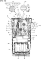
- Fig. 28 illustrates a plan view corresponding to Fig. 2 of the first embodiment and showing a rear internal structure of a device body of a print label producing device in the third background example.
- the double-faced adhesive tape 150 wound onto the adhesive tape roll 14 disposed in the housing 11A of the cartridge 11 of this background example is configured to include: as shown in an enlarged view of Fig.
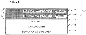
- an adhesive layer 163U with predetermined particles (a pigment in this example; it may be a glitter pigment in particular; the same applies hereinafter) added; an adhesive layer 163L with particles of the same material as in the adhesive layer 163U (the glitter pigment in this example; the same applies hereinafter) added; the colored layer 180; the film layer 151, the adhesive layer 170; and the separation material layer 152; laminated in the mentioned order from the spool 50 lying on the radial center side (corresponding to the upper side in Fig. 29 described later) toward the radial outside (corresponding to the lower side in Fig. 29 described layer). Similar to the above, as shown in Fig.
- the print-receiving tape roll 15 is made up by winding the print-receiving tape 110 (corresponding to a cover film) having a transmittance of 20 % or more for example around the spool 60.
- the housing 11A comprises the ink ribbon roll 16 similar to the above.
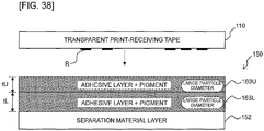
- Fig. 29 is an explanatory view showing a layered structure of the print-receiving tape 110 and the double-faced adhesive tape 150.
- the double-faced adhesive tape 150 includes: the film layer 151; the colored layer 180 disposed in contact with the film layer 151 on the upper side of the diagram (one side in the thickness direction in the structures of Figs. 29 to 31 ); the adhesive layer 163L (corresponding to a first-particle-containing adhesive layer) disposed in contact with the colored layer on the upper side of the diagram (one side in the thickness direction in the structures of Figs. 29 to 31 ) and having the pigment added at a desired volume ratio; the adhesive layer 163U (corresponding to a second-particle-containing adhesive layer) disposed in contact with the adhesive layer 163L on the upper side of the diagram (one side in the thickness direction in the structures of Figs.
- the adhesive layer 170 (corresponding to an affixing adhesive layer) disposed in contact with the film layer 151 on the lower side of the diagram (the other side in the thickness direction in the structures of Figs. 29 to 31 ); and the separation material layer 152 disposed in contact with the adhesive layer 170 on the lower side of the diagram (the other side in the thickness direction in the structures of Figs. 29 to 31 ) so as to cover the adhesive layer 170.
- this background example has a feature that the pigment in the adhesive layers 163U and 163L has an average particle diameter of 30 ⁇ m or more.
- the average particle diameter can be measured by the technique similar to the above.
- the volume ratio of the pigment in the adhesive layer 163U is smaller than the volume ratio of the pigment in the adhesive layer 163L. Specifically, the volume ratio of the pigment in the adhesive layer 163L is 1.5 times or more the volume ratio in the adhesive layer 163U.
- a thickness tL of the adhesive layer 163L is greater than a thickness tU of the adhesive layer 163U. Specifically the thickness tL of the adhesive layer 163L is 1.5 times or more the thickness tU of the adhesive layer 163U.
- the adhesive force of the adhesive layer 163U is 3 [N]/10 [mm] or more.
- the adhesive force (bonding force) is measured in conformity with JIS-Z0237. To put it briefly, a surface to be measured is affixed to an SUS304 stainless plate and, after the elapse of a certain period of time, a tensile tester is used to perform a measurement separating at an angle of 180 degrees at a speed of 300 mm/min (hereinafter, the same will apply to modification examples, background examples and other embodiments described later).
- the print-receiving tape 110 has print R as described above on a surface on the side facing the double-faced adhesive tape 150 (the lower side of the diagram; the other side in the thickness direction in the structures of Figs. 29 to 31 ).
- the print-receiving tape 110 is bonded via the adhesive layer 163U to the double-faced adhesive tape 150.
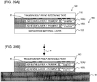
- Fig. 30A shows a layered structure of the print tape 100 formed by bonding the print-receiving tape 110 and the double-faced adhesive tape 150 together
- Fig. 30B shows a state where the print tape 100 is adhered via the adhesive layer 170 to the adherend M with the separation material layer 152 being separated from the print tape 100.
- the print tape 100 is made up by laminating, from the upper side of the diagram (one side in the thickness direction in the structures of Figs. 29 to 31 ) toward the lower side thereof (the other side in the thickness direction in Figs.
- the print-receiving tape 110 the adhesive layer 163U (to which the glitter pigment is added), the adhesive layer 163L (to which the glitter pigment is added), the colored layer 180, the film layer 151, the adhesive layer 170, and the separation material layer 152, in the mentioned order.
- the adhesive layer 163L may be disposed in contact with the film layer 151 on the upper side of the diagram (one side in the thickness direction in the structures of Figs. 29 to 31 ), without interposing the colored layer 180 between the adhesive layer 163L and the film layer 151.
- three or more adhesive layers having common particles, inclusive of the two adhesive layers 163U and 163L, may be disposed adjacent to one another.
- a manufacturing process of the double-faced adhesive tape 150 will next be described with reference to Figs. 32 to 34 .
- the film layer 151 having the colored layer 180 formed thereon by a known printing technique for example is fed out from the film roll FR and is supplied to the adhesive coating head AH.
- an adhesive of the above composition is applied to a surface of the film layer 151 opposite to the colored layer 180, to obtain a three-layered structure including the colored layer 180, the film layer 151, and the adhesive layer 170, after which the structure passes through the first drying chamber D1, the second drying chamber D2, the third drying chamber D3, the fourth drying chamber D4, and the fifth drying chamber D5, in the mentioned order, to undergo a five-stage drying process.
- the number of the drying chambers is not limited to five.
- the separation material layer 152 fed out separately from the separation material roll SR is bonded to the adhesive layer 170 so that the tape of the three-layered structure turns into a tape of a four-layered structure, which is wound onto the first tape roll TR1.
- the tape of the four-layered structure including the colored layer 180, the film layer 151, the adhesive layer 170, and the separation material layer 152 is fed out from the first tape roll TR1 and is supplied to the adhesive coating head AH in the same manner as the above.
- an adhesive (containing the glitter pigment as the particles for example) of the above composition is applied to a surface of the colored layer 180 opposite to the film layer 151, to obtain a five-layered structure including the adhesive layer 163L (having the glitter pigment added), the colored layer 180, the film layer 151, the adhesive layer 170, and the separation material layer 152, after which similarly to the above, the structure passes through the first to fifth drying chambers D1 to D5, in the mentioned order, to undergo the drying process and is wound onto the second tape roll TR2.
- the tape of the five-layered structure including the adhesive layer 163L, the colored layer 180, the film layer 151, the adhesive layer 170, and the separation material layer 152 is fed out from the second tape roll R2 and is supplied to the adhesive coating head AH in the same manner as the above.
- an adhesive containing the same particles as the above, e.g.
- the glitter pigment) the permeable glitter pigment) of the above composition is applied to a surface of the adhesive layer 163L opposite to the colored layer 180, to obtain a six-layered structure including the adhesive layer 163U (having the glitter pigment added), the adhesive layer 163L (having the glitter pigment added), the colored layer 180, the film layer 151, the adhesive layer 170, and the separation material layer 152, after which similarly to the above, the structure passes through the first to fifth drying chambers D1 to D5, in the mentioned order, to undergo the drying process to complete the double-faced adhesive tape 150.
- the thus completed double-faced adhesive tape 150 is wound onto the third tape roll TR3.
- Figs. 32 to 34 the case has been described by way of example where the adhesive coating head AH is disposed only at a single location, another adhesive coating head AH may separately be disposed downstream of the drying chamber D5 along the transport path. In this case, intactly after the coating process of the adhesive layer 163L and the drying process through the drying chambers D1 to D5 in Fig. 33 , the coating process of the adhesive layer 163U (described using Fig. 34 ) can be performed.
- a solvent (used at the time of dilution) contained in the interior of a layer adhesively coated at the adhesive coating head AH may not fully volatilize even through the subsequent drying process in the drying chambers D1 to D5 and may remain within the adhesive layer (see broken line portions of Fig. 35 ). Since the adhesive performance of the adhesive layer is adversely affected if the solvent remains within the adhesive layer, there is a need to lower the coating speed or strengthen the drying conditions in order to avoid the adverse effect, resulting in increased manufacturing costs. The above trend becomes noticeable esp. when using particles with a large particle diameter (particles with an average particle diameter of 30 ⁇ m or more as in this background example for example).
- the adhesive layer with the above particles added is divided into two (the adhesive layer 163L and the adhesive layer 163U) (see Fig. 36A ) so that the adhesive layer 163L with the above particles added is first disposed on one side (the upper side in Figs. 29 to 31 ) in the thickness direction of the film layer 151 (see the overall process shown in Fig. 33 ) while the adhesive layer 163U with the same particles added is disposed on one side (the upper side in Figs. 29 to 31 ) in the thickness of the adhesive layer 163L.
- the thickness of one adhesive layer 163U (or adhesive layer 163L) can be reduced so that the solvent can easily dry through the drying process in the drying chambers D1 to D5 (see solid arrows in Fig. 36B ) so that the lowering in the adhesive performance of the adhesive layers 163U and 163L arising from the residual solvent can be suppressed.
- the pigment is added as the above particles to the adhesive layer 163L and the adhesive layer 163U. This enables the brilliance from the pigment to be secured.
- the volume ratio of the particles (the pigment in the above example) in the adhesive layer 163U is smaller than the volume ratio of the pigment in the adhesive layer 163L. This enables the adhesive performance of the adhesive layer 163U exposed on the surface to be secured. In other words, the bonding performance of the entire tape can be secured.
- the volume ratio of the pigment in the adhesive layer 163L is 1.5 times or more the volume ratio in the adhesive layer 163U. This has the following technical significance.
- the second-particle-containing adhesive layer may have a smaller volume ratio, the reason is that the second pigment is on the bonding side and therefore requires an adhesive force.
- the first pigment is increased to compensate for the decrease in the second pigment.
- the bonding force is insufficient, requiring an increase in the thickness of the adhesive layer.
- 1.5 times or more preferably, 2 times or more is preferred.
- the adhesive layer 163L disposed on the film layer 151 (having the colored layer 180 formed thereon) is bonded to the colored layer 180 at the time of manufacturing in the state where it is managed in the factory manufacturing facility shown in Figs. 32 to 34 for example.
- the adhesive layer 163U is bonded to the print-receiving tape 110 within the print label producing device 1 at the time of the print label production as described hereinabove.
- the bonding force of the adhesive layer 163U needs to be greater than that of the adhesive layer 163L.
- this third background example can deal with the above by setting the volume ratio of the particles in the adhesive layer 163U to be smaller than the volume ratio of the particles in the adhesive layer 163L.
- the thickness tL of the adhesive layer 163L is set to be greater (than the thickness tU of the adhesive layer 163U) so that the volume ratio of the particles in the adhesive layer 163L can further be increased.
- Such an increase allows the residual amount of the solvent in the adhesive layer 163L to relatively increase but allows the residual amount of the solvent in the adhesive layer 163U to relatively decrease.
- the thickness tL of the adhesive layer 163L is 1.5 times or more the thickness tU of the adhesive layer 163U. This has the following technique significance.
- the second pigment is reduced to 2/3 or less (desirably, 1/2 or less) to obtain a minimum thickness capable of securing the bonding force of 3 N/10 mm (for the purpose of preventing the total layer thickness from increasing). Such a reduction increases the ratio of the first pigment, requiring the 1.5 times or more thickness.
- the adhesive force of the adhesive layer 163U is 3 [N]/10 [mm] or more. As a result, the adhesiveness by the adhesive layer 163U can be ensured.
- the film layer 151 and the adhesive layer 170 may be removed.
- Such a modification example will be described with reference to Figs. 37 to 39 .
- the same reference numerals are imparted to parts equivalent to those of the third background example and explanations thereof will appropriately be omitted or simplified.
- Fig. 37 illustrates a plan view corresponding to Fig. 28 of the third background example and showing a rear internal structure of a device body of a print label producing device in this modification example.
- the double-faced adhesive tape 150 wound onto the adhesive tape roll 14 disposed in the housing 11A of the cartridge 11 of this modification example is configured to include: as shown in an enlarged view of Fig.
- the print-receiving tape roll 15 is made up by winding the print-receiving tape 110 (corresponding to the cover film) having a transmittance of 20 % or more for example around the spool 60.
- the housing 11A comprises the ink ribbon roll 16 similar to the above.
- Fig. 38 is an explanatory view showing a layered structure of the print-receiving tape 110 and the double-faced adhesive tape 150.
- the double-faced adhesive tape 150 includes: the adhesive layer 163L (corresponding to the first-particle-containing adhesive layer) to which the pigment is added at a desired volume ratio; the adhesive layer 163U (corresponding to the second-particle-containing adhesive layer) disposed in contact with the adhesive layer 163L on the upper side of the diagram (one side in the thickness direction in this modification example) and having the pigment of the same material as in the adhesive layer 163L added at a desired volume ratio; and the separation material layer 152 disposed in contact with the adhesive layer 163L on the lower side of the diagram (the other side in the thickness direction in this modification example) so as to cover the adhesive layer 163L.
- the adhesive layer 163L corresponding to the first-particle-containing adhesive layer
- the adhesive layer 163U corresponding to the second-particle-containing adhesive layer
- the separation material layer 152 disposed in contact with the adhesive layer 163L on the lower side of the diagram (the other side in the thickness direction in this modification example) so as to cover the adhesive layer 163L.
- Fig. 39A shows a layered structure of the print tape 100 formed by bonding the print-receiving tape 110 and the double-faced adhesive tape 150 together
- Fig. 39B shows a state where the print tape 100 is adhered via the adhesive layer 162 to the adherend M with the separation material layer 152 being separated from the print tape 100.
- the print tape 100 is made up by laminating, from the upper side of the diagram (one side in the thickness direction in this modification example) toward the lower side thereof (the other side in the thickness direction in this modification example), the print-receiving tape 110, the adhesive layer 163U (to which a pigment is added), the adhesive layer 163L (to which the pigment is added), and the separation material layer 152, in the mentioned order.
- This modification example also presents an advantage similar to that of the second background example.
- the third background example is not limited to the above mode and can variously be modified without departing from its spirit and technical idea. Modification examples thereof will be described hereinbelow in order.
- This modification example uses a cartridge called a so-called non-laminated type (in more detail, receptor type), in the same manner as in Fig. 15 of the second background example described above.
- the cartridge 11 for use in this modification example comprises, within the housing 11A, similarly to Fig. 15 , the adhesive tape roll 14 (of which detailed Layered Structure will be described later), the ink ribbon roll 16, the ink ribbon take-up roller 17, and the feeding roller 18.
- the adhesive tape roll 14 is made up by winding the adhesive tape 150N related to this modification example around the spool 50.
- the adhesive tape 150N includes: the image receiving layer 210; the colored layer 180; the transparent film layer 151A that is transparent (or translucent is also acceptable; the same will apply hereinafter) similar to the above; the adhesive layer 163L to which predetermined particles (a pigment in this example; it may be a glitter pigment in particular; the same will apply hereinafter) similar to those in Fig.
- Fig. 41A is an explanatory view showing a layered structure of the adhesive tape 150N and the print tape 100N.
- the adhesive tape 150N includes: the transparent film layer 151A; the colored layer 180 disposed in contact with the transparent film layer 151A on the upper side of the diagram (the other side in the thickness direction in the structures of Figs. 40 to 44 ); the image receiving layer 210 disposed in contact with the colored layer 180 on the upper side of the diagram (the other side in the thickness direction in the structures of Figs. 40 to 44 ); the adhesive layer 163L (corresponding to the first-particle-containing adhesive layer) disposed in contact with the transparent film layer 151A on the lower side of the diagram (one sided in the thickness direction in the structures of Figs.
- the adhesive layer 163U (corresponding to the second-particle-containing adhesive layer) disposed in contact with the adhesive layer 163L on the lower side of the diagram (one side in the thickness direction in the structures of Figs. 40 to 44 ) and having the pigment of the same material as in the adhesive layer 163L added at a desired volume ratio; and the separation material layer 152 disposed in contact with the adhesive layer 163U on the lower side of the diagram (one side in the thickness direction in the structures of Figs. 40 to 44 ) so as to cover the adhesive layer 163U.
- the average particle diameter of the pigment in the adhesive layers 163U and 163L is 30 ⁇ m or more.
- the average particle diameter can be measured by the technique similar to the above.
- the volume ratio of the pigment in the adhesive layer 163U is smaller than the volume ratio of the pigment in the adhesive layer 163L.
- the volume ratio of the pigment in the adhesive layer 163L is 2 times or more the volume ratio in the adhesive layer 163U.
- the volume ratio can be measured by the technique described above.
- the thickness tL of the adhesive layer 163L is greater than the thickness tU of the adhesive layer 163U.
- the thickness tL of the adhesive layer 163L is 1.5 times or more the thickness tU of the adhesive layer 163U.
- the adhesive force of the adhesive layer 163U is 3 [N]/10 [mm] or more.
- the colored layer 180 has a transmittance of 20 % or more.
- the image receiving layer 210 also has a transmittance of 20 % or more.
- Fig. 41B shows a layered structure of the print tape 100N having print R formed on the image receiving layer 210 of the adhesive tape 150N.
- a manufacturing process of the adhesive tape 150N will next be described using Figs. 42 and 43 .
- the transparent film layer 151A having the image receiving layer 210 and the colored layer 180 formed thereon by a known printing technique is fed out from the film roll FR and is supplied to the adhesive coating head AH.
- an adhesive (containing the pigment) of the above composition is applied to a surface of the transparent film layer 151A opposite to the colored layer 180, to obtain a four-layered structure including the image receiving layer 210, the colored layer 180, the transparent film layer 151A, and the adhesive layer 163L (with the pigment added), after which the structure passes through the first drying chamber D1, the second drying chamber D2, the third drying chamber D3, the fourth drying chamber D4, and the fifth drying chamber D5, in the mentioned order, to undergo the five-stage drying process, and is wound onto the first tape roll TR1.
- the number of the drying chambers is not limited to five.
- the tape of the four-layered structure including the image receiving layer 210, the colored layer 180, the transparent film layer 151A, and the adhesive layer 163L is fed out from the first tape roll TR1 and is supplied to the adhesive coating head AH in the same manner as the above.
- an adhesive (containing the same pigment as the above) of the above composition is applied to a surface of the adhesive layer 163L opposite to the transparent film layer 151A, to obtain a five-layered structure including the image receiving layer 210, the colored layer 180, the transparent film layer 151A, the adhesive layer 163L, and the adhesive layer 163U (with the pigment added), after which similarly to the above, the structure passes through the first to fifth drying chambers D1 to D5, in the mentioned order, to undergo the drying process.
- the separation material layer 152 separately fed out from the separation material roll SR is bonded to the adhesive layer 163U of the tape of the 5-layered structure, to complete the adhesive tape 150N of a six-layered structure including the image receiving layer 210, the colored layer 180, the transparent film layer 151A, the adhesive layer 163L, the adhesive layer 163U, and the separation material layer 152.
- the thus completed adhesive tape 150N is wound onto the second tape roll TR2.
- the configuration may be such that the image receiving layer 210 is disposed in contact with the transparent film layer 151A on the upper side of the diagram (the other side in the thickness direction in this modification example), without interposing the colored layer 180 between the image receiving layer 210 and the transparent film layer 151A.
- the colored layer 180 may be disposed in contact with the transparent film layer 151A on the upper side of the diagram (the other side in the thickness direction in this modification example), without disposing the image receiving layer 210.
- This modification example can also present an advantage similar to that of the third background example.
- the adhesive layer with particles added is divided into two (the adhesive layer 163L and the adhesive layer 163U) so that the adhesive layer 163L with the above particles added is disposed on one side (the lower side in Fig. 41 ) in the thickness direction of the transparent film layer 151A while the adhesive layer 163U with the same particles added is disposed on one side (the lower side in Fig. 41 ) in the thickness direction of the adhesive layer 163L.
- the thickness of one adhesive layer 163U (or adhesive layer 163L) can be reduced so that the solvent can easily dry through the drying process in the drying chambers D1 to D5 so that the lowering in the adhesive performance of the adhesive layers 163U and 163L arising from the residual solvent can be suppressed.
- the glitter pigment is added as the above particles to the adhesive layer 163L and the adhesive layer 163U, enabling the brilliance from the pigment to be secured.
- the volume ratio of the particles (the pigment in the above example) in the adhesive layer 163U is smaller than the volume ratio of the pigment in the adhesive layer 163L, thereby enabling the adhesive performance of the adhesive layer 163U exposed on the surface to be secured, i.e., enabling the bonding performance of the entire tape to be secured.
- the thickness tL of the adhesive layer 163L is set to be greater (than the thickness tU of the adhesive layer 163U) so that the volume ratio of the particles in the adhesive layer 163L can further be increased.
- the adhesive force of the adhesive layer 163U is 3 [N]/10 [mm] or more, whereby the adhesiveness by the adhesive layer 163U can be ensured.
- the adhesive layer 163L disposed on the transparent film layer 151A is bonded to the transparent film layer 151A while being managed in the factory manufacturing facility for example at the time of manufacturing, as described above using Fig. 42 .
- the adhesive layer 163U needs to have a bonding force greater than that of the adhesive layer 163L because the adherend has not yet been determined and because the adhesion is made by the user.
- This modification example can deal with the above by setting the volume ratio of the pigment in the adhesive layer 163U to be less than the volume ratio of the pigment in the adhesive layer 163L.
- the transparent film layer 151A and the colored layer 180 may be interchanged so that the image receiving layer 210, the transparent film layer 151A, the colored layer 180, the adhesive layer 163L, the adhesive layer 163U, and the separation material layer 152 are laminated in the mentioned order from the upper side (the other side in the thickness direction) of the diagram toward the lower side (one side in the thickness direction) of the diagram.
- the colored layer 180 may be removed from the layered structure of the adhesive tape 150N shown in Fig. 44A (in this case, the same layered structure as in Fig. 41C results).
- the image receiving layer 210 may be removed from the layered structure of the adhesive tape 150N shown in Fig. 44A .
- the transparent film layer 151A and the colored layer 180 may be removed from the structure shown in Fig. 44A .
- Such a modification example will be described with reference to Fig. 46 .
- the same reference numerals are imparted to parts equivalent to those in the third background example and its modification examples, and explanations thereof will appropriately be omitted or simplified.
- Fig. 45 illustrates a plan view corresponding to Fig. 40 and showing a rear internal structure of a device body of a print label producing device in this modification example.
- the cartridge 11 for use in this modification example comprises, within the interior of the housing 11A, the adhesive tape roll 14, the ink ribbon roll 16, the ink ribbon take-up roller 17, and the feeding roller 18.
- the adhesive tape roll 14 is made up by winding the adhesive tape 150N in relation to this modification example around the spool 50.
- the adhesive tape 150N includes: the image receiving layer 210 similar to the above; the adhesive layer 163L with predetermined particles (a pigment in this example) similar to the above added; the adhesive layer 163U with particles (the pigment in this example; the same will apply hereinafter) of the same material as in the adhesive layer 163L added; and the separation material layer 152, laminated in the mentioned order from the spool 50 lying on the radial center side in Fig. 45 (corresponding to the upper side in Fig. 46 described later) toward the radial outside (corresponding to the lower side in Fig. 46 described later).
- Fig. 46A is an explanatory view showing a layered structure of the adhesive tape 150N according to this modification example.
- the adhesive tape 150N includes: the adhesive layer 163L (corresponding to the first-particle-containing adhesive layer) having the pigment added at a desired volume ratio; the image receiving layer 210 disposed in contact with the adhesive layer 163L on the upper side of the diagram (the other side in the thickness direction in this modification example); the adhesive layer 163U (corresponding to the second-particle-containing adhesive layer) disposed in contact with the adhesive layer 163L on the lower side of the diagram (one side in the thickness direction in this modification example) and having the pigment of the same material as in the adhesive layer 163L added at a desired volume ratio; and the separation material layer 152 disposed in contact with the adhesive layer 163U on the lower side of the diagram (one side in the thickness direction in this modification example) so as to cover the adhesive layer 163U.
- the adhesive layer 163L corresponding to the first-particle-containing adhesive layer
- the image receiving layer 210 disposed in contact with the adhesive layer 163L on the upper side of the diagram (the other side in the thickness direction in this modification example)
- Fig. 46B shows a layered structure of the print tape 100N in which print R is formed on the image receiving layer 210 of the adhesive tape 150N.
- This modification example also presents an advantage similar to the above.
Landscapes
- Chemical & Material Sciences (AREA)
- Organic Chemistry (AREA)
- Physics & Mathematics (AREA)
- General Physics & Mathematics (AREA)
- Engineering & Computer Science (AREA)
- Theoretical Computer Science (AREA)
- Adhesive Tapes (AREA)
- Laminated Bodies (AREA)
- Adhesives Or Adhesive Processes (AREA)
Claims (14)
- Cartouche de bande adhésive (11), comprenant :un boîtier ; etun rouleau de bande adhésive qui est disposé dans ledit boîtier (11A) et enroule une bande adhésive à double face (150),ladite bande adhésive à double face (150) comprenant :une couche de matériau de base (151) ;une première couche adhésive (162 ; 162A ; 162B) qui est disposée sur un côté de ladite couche de matériau de base (151) dans une direction d'épaisseur et comprend un adhésif avec un premier pigment ajouté ;une deuxième couche adhésive (161 ; 161B) qui est disposée sur l'un côté de ladite première couche adhésive (162 ; 162A, 162B) dans la direction d'épaisseur et comprend un adhésif avec un second pigment ajouté ;une troisième couche adhésive (170) qui est disposée sur l'autre côté de ladite couche de matériau de base (151) dans la direction d'épaisseur et comprend un adhésif ; etune couche de matériau de séparation (152) qui est disposée sur ledit autre côté de ladite troisième couche adhésive (170) dans la direction d'épaisseur ;un rapport de volume dudit premier pigment dans ladite première couche adhésive (162 ; 162A ; 162B) étant supérieur à un rapport de volume dudit second pigment dans ladite deuxième couche adhésive (161 ; 161B).
- Cartouche de bande adhésive (11) selon la revendication 1, dans laquelle
le rapport de volume dudit premier pigment dans ladite première couche adhésive (162 ; 162A ; 162B) est 1,5 fois ou plus le rapport de volume dudit second pigment dans ladite deuxième couche adhésive (161 ; 161B). - Cartouche de bande adhésive (11) selon la revendication 1 ou 2, dans laquelle
le rapport de volume dudit premier pigment dans ladite première couche adhésive (162 ; 162A ; 162B) est de 5 % ou plus et de 50 % ou moins, et dans laquelle
le rapport de volume dudit second pigment dans ladite deuxième couche adhésive (161 ; 161B) est supérieur à 5 % et 50 % ou moins. - Cartouche de bande adhésive (11) selon l'une quelconque des revendications 1 ou 3, dans laquelle
un diamètre moyen des particules, tel que mesuré par un procédé de dispersion par diffraction laser, dudit premier pigment est inférieur à un diamètre moyen des particules, tel que mesuré par ledit procédé de dispersion par diffraction laser, dudit second pigment. - Cartouche de bande adhésive (11) selon la revendication 4, dans laquelle
le diamètre moyen des particules dudit premier pigment est inférieur à 30 µm, et dans laquelle
le diamètre moyen des particules dudit second pigment est égal ou supérieur à 40 µm. - Cartouche de bande adhésive (11) selon la revendication 5, dans laquelle
le diamètre moyen des particules dudit premier pigment est égal ou inférieur à 10 µm, et dans laquelle
le diamètre moyen des particules dudit second pigment est égal ou supérieur à 60 µm. - Cartouche de bande adhésive (11) selon l'une quelconque des revendications 1 à 6, dans laquelle
ledit premier pigment et ledit second pigment sont faits du même matériau l'un que l'autre. - Cartouche de bande adhésive (11) selon la revendication 1, dans laquelle
ledit premier pigment est un pigment uni ou un pigment brillant, et dans laquelle
ledit second pigment est un pigment brillant. - Cartouche de bande adhésive (11) selon l'une quelconque des revendications 1 à 8, dans laquelle
une épaisseur de ladite deuxième couche adhésive (161 ; 161B) est inférieure à une épaisseur de ladite troisième couche adhésive (170), dans laquelle
une épaisseur de ladite première couche adhésive (162 ; 162A ; 162B) est inférieure à l'épaisseur de ladite troisième couche adhésive (170), et dans laquelle
une somme de l'épaisseur de ladite première couche adhésive (162 ; 162A ; 162B) et de l'épaisseur de ladite deuxième couche adhésive (161 ; 161B) est supérieure à l'épaisseur de ladite troisième couche adhésive (170). - Cartouche de bande adhésive (11) selon l'une quelconque des revendications 1 à 9, dans laquelle
ladite première couche adhésive (162A ; 162B) est disposée en contact avec ledit un côté de ladite couche de matériau de base (151) dans la direction d'épaisseur. - Cartouche de bande adhésive (11) selon l'une quelconque des revendications 1 à 9, comprenant en outre :
une couche colorée (180) qui est disposée sur ledit un côté de ladite couche de matériau de base (151) dans la direction d'épaisseur et disposée sur ledit autre côté de ladite première couche adhésive (162 ; 162A ; 162B) dans la direction d'épaisseur. - Cartouche de bande adhésive (11) selon l'une quelconque des revendications 1 à 11, comprenant en outre : dans ledit boîtier (11A),
un rouleau de film de couverture (15) qui enroule un film de couverture (110) destiné à être lié audit un côté de ladite deuxième couche adhésive (161 ; 161B) de ladite bande adhésive à double face (150) dans la direction d'épaisseur ; et
un rouleau de ruban d'encre (16) qui enroule un ruban d'encre qui transfère de l'encre audit autre côté dudit film de couverture (110) dans la direction d'épaisseur, le film de couverture (110) étant dévidé dudit rouleau de film de couverture (15). - Rouleau de bande adhésive (14) qui enroule une bande adhésive à double face (150), ladite bande adhésive à double face (150) comprenant :une couche de matériau de base (151) ;une première couche adhésive (162 ; 162A ; 162B) qui est disposée sur un côté de ladite couche de matériau de base (151) dans une direction d'épaisseur et comprend un adhésif avec un premier pigment ajouté ;une deuxième couche adhésive (161 ; 161B) qui est disposée sur l'un côté de ladite première couche adhésive (162 ; 162A ; 162B) dans la direction d'épaisseur et comprend un adhésif avec un second pigment ajouté ;une troisième couche adhésive (170) qui est disposée sur l'autre côté de ladite couche de matériau de base (151) dans la direction d'épaisseur et comprend un adhésif ; etune couche de matériau de séparation (152) qui est disposée sur ledit autre côté de ladite troisième couche adhésive (170) dans la direction d'épaisseur ;un rapport de volume dudit premier pigment dans ladite première couche adhésive (162 ; 162A ; 162B) étant supérieur à un rapport de volume dudit second pigment dans ladite deuxième couche adhésive (161 ; 161B).
- Procédé de fabrication d'un rouleau de bande adhésive (14), comprenant :l'application d'un adhésif sur un côté d'une couche de matériau de base (151) dans une direction d'épaisseur avec un premier pigment ajouté, et la formation d'une première couche adhésive (162 ; 162A ; 162B) ;l'application d'un adhésif sur ledit un côté de ladite première couche adhésive (162 ; 162A ; 162B) dans la direction d'épaisseur avec un second pigment ajouté, à un rapport de volume inférieur à un rapport de volume dudit premier pigment dans ladite première couche adhésive (162 ; 162A ; 162B), et la formation d'une deuxième couche adhésive (161 ; 161B) ;l'application d'un adhésif sur l'autre côté de ladite couche de matériau de base (151) dans la direction d'épaisseur et la formation d'une troisième couche adhésive (170), et la liaison d'une couche de matériau de séparation (152) audit autre côté de ladite troisième couche adhésive (170) dans la direction d'épaisseur ; etl'enroulement d'une bande adhésive incluant ladite couche de matériau de base (151), ladite première couche adhésive (162 ; 162A ; 162B), ladite deuxième couche adhésive (161 ; 161B), ladite troisième couche adhésive (170), et ladite couche de matériau de séparation (152), et la formation dudit rouleau de bande adhésive (14).
Applications Claiming Priority (1)
| Application Number | Priority Date | Filing Date | Title |
|---|---|---|---|
| JP2016195291A JP6663567B2 (ja) | 2016-09-30 | 2016-09-30 | 粘着テープカートリッジ及び粘着テープロール並びに粘着テープロールの製造方法 |
Publications (2)
| Publication Number | Publication Date |
|---|---|
| EP3300913A1 EP3300913A1 (fr) | 2018-04-04 |
| EP3300913B1 true EP3300913B1 (fr) | 2021-04-21 |
Family
ID=59969093
Family Applications (1)
| Application Number | Title | Priority Date | Filing Date |
|---|---|---|---|
| EP17193274.2A Active EP3300913B1 (fr) | 2016-09-30 | 2017-09-26 | Cartouche de ruban adhésif, rouleau de ruban adhésif et procédé de fabrication d'un rouleau de ruban adhésif |
Country Status (3)
| Country | Link |
|---|---|
| US (1) | US10532907B2 (fr) |
| EP (1) | EP3300913B1 (fr) |
| JP (1) | JP6663567B2 (fr) |
Families Citing this family (2)
| Publication number | Priority date | Publication date | Assignee | Title |
|---|---|---|---|---|
| JP6729258B2 (ja) * | 2016-09-30 | 2020-07-22 | ブラザー工業株式会社 | 粘着テープカートリッジ及び粘着テープロールの製造方法 |
| JP6663568B2 (ja) * | 2016-09-30 | 2020-03-13 | ブラザー工業株式会社 | 粘着テープカートリッジ及び粘着テープロール並びに粘着テープロールの製造方法 |
Family Cites Families (13)
| Publication number | Priority date | Publication date | Assignee | Title |
|---|---|---|---|---|
| US4436377A (en) * | 1980-11-06 | 1984-03-13 | Morgan Adhesives Company | Transmissive reflector including nacreous, pressure sensitive adhesive layer |
| US6503620B1 (en) * | 1999-10-29 | 2003-01-07 | Avery Dennison Corporation | Multilayer composite PSA constructions |
| JP2002194301A (ja) * | 2000-12-26 | 2002-07-10 | Teraoka Seisakusho:Kk | 両面粘着テープ |
| AU2003292216A1 (en) * | 2002-12-17 | 2004-07-09 | Merck Patent Gmbh | Silvery white interference pigments having a high luster and based on transparent substrate laminae |
| US7153981B2 (en) * | 2004-07-27 | 2006-12-26 | E. I. Du Pont De Nemours And Company | Supercritical fluid phase synthesis of methylene lactones using oxynitride catalyst |
| WO2006049107A1 (fr) * | 2004-11-05 | 2006-05-11 | Brother Kogyo Kabushiki Kaisha | Rouleau de bande d’etiquettes, bande d’etiquettes et cartouche d’element de circuit d’etiquette sans fil |
| EP1803575B1 (fr) * | 2005-12-28 | 2015-09-23 | Brother Kogyo Kabushiki Kaisha | Ruban à imprimer et cassette pour bande |
| JP2007188320A (ja) * | 2006-01-13 | 2007-07-26 | Brother Ind Ltd | タグテープ、印字済みタグラベル用テープ |
| JP2007286194A (ja) * | 2006-04-13 | 2007-11-01 | Brother Ind Ltd | 無線タグラベル |
| EP2018974B1 (fr) * | 2006-05-18 | 2011-06-22 | Brother Kogyo Kabushiki Kaisha | Ruban d'impression et cassette d'impression |
| EP2438127B1 (fr) * | 2009-06-04 | 2013-07-31 | Italgraf S.R.L. | Étiquette imprimable repositionable et son procédé de production |
| DE102009046625A1 (de) * | 2009-11-11 | 2011-05-12 | Tesa Se | Etikett mit Effektpigmenten |
| JP5874289B2 (ja) * | 2011-10-07 | 2016-03-02 | ブラザー工業株式会社 | テープカセット及びテープ印字装置 |
-
2016
- 2016-09-30 JP JP2016195291A patent/JP6663567B2/ja active Active
-
2017
- 2017-09-26 EP EP17193274.2A patent/EP3300913B1/fr active Active
- 2017-09-29 US US15/719,910 patent/US10532907B2/en active Active
Non-Patent Citations (1)
| Title |
|---|
| None * |
Also Published As
| Publication number | Publication date |
|---|---|
| US10532907B2 (en) | 2020-01-14 |
| US20180094170A1 (en) | 2018-04-05 |
| JP2018058928A (ja) | 2018-04-12 |
| EP3300913A1 (fr) | 2018-04-04 |
| JP6663567B2 (ja) | 2020-03-13 |
Similar Documents
| Publication | Publication Date | Title |
|---|---|---|
| US10995241B2 (en) | Adhesive tape cartridge, adhesive tape roll, and method of manufacturing an adhesive tape roll | |
| EP3301140B1 (fr) | Cartouche de ruban adhésif, rouleau de ruban adhésif et procédé de fabrication d'un rouleau de ruban adhésif | |
| US10894902B2 (en) | Adhesive tape cartridge and adhesive tape roll | |
| EP3300910B1 (fr) | Cartouche de ruban adhésif, rouleau de ruban adhésif et procédé de production d'un rouleau de ruban adhésif | |
| EP3300913B1 (fr) | Cartouche de ruban adhésif, rouleau de ruban adhésif et procédé de fabrication d'un rouleau de ruban adhésif | |
| EP3300912B1 (fr) | Cartouche de ruban adhésif, rouleau de ruban adhésif et procédé de fabrication d'un rouleau de ruban adhésif | |
| US11078384B2 (en) | Adhesive tape cartridge, adhesive tape roll, and method of manufacturing an adhesive tape roll | |
| US10870259B2 (en) | Adhesive tape cartridge, adhesive tape roll, and method of manufacturing an adhesive tape roll | |
| US10569577B2 (en) | Adhesive tape cartridge, adhesive tape roll, production method for adhesive tape roll, and printer having cartridge | |
| JP6665750B2 (ja) | 粘着テープカートリッジ及び粘着テープロール並びに粘着テープロールの製造方法 |
Legal Events
| Date | Code | Title | Description |
|---|---|---|---|
| PUAI | Public reference made under article 153(3) epc to a published international application that has entered the european phase |
Free format text: ORIGINAL CODE: 0009012 |
|
| STAA | Information on the status of an ep patent application or granted ep patent |
Free format text: STATUS: THE APPLICATION HAS BEEN PUBLISHED |
|
| AK | Designated contracting states |
Kind code of ref document: A1 Designated state(s): AL AT BE BG CH CY CZ DE DK EE ES FI FR GB GR HR HU IE IS IT LI LT LU LV MC MK MT NL NO PL PT RO RS SE SI SK SM TR |
|
| AX | Request for extension of the european patent |
Extension state: BA ME |
|
| STAA | Information on the status of an ep patent application or granted ep patent |
Free format text: STATUS: REQUEST FOR EXAMINATION WAS MADE |
|
| 17P | Request for examination filed |
Effective date: 20180919 |
|
| RBV | Designated contracting states (corrected) |
Designated state(s): AL AT BE BG CH CY CZ DE DK EE ES FI FR GB GR HR HU IE IS IT LI LT LU LV MC MK MT NL NO PL PT RO RS SE SI SK SM TR |
|
| REG | Reference to a national code |
Ref country code: DE Ref legal event code: R079 Ref document number: 602017036992 Country of ref document: DE Free format text: PREVIOUS MAIN CLASS: B41J0015040000 Ipc: C09J0007300000 |
|
| RIC1 | Information provided on ipc code assigned before grant |
Ipc: C09J 7/30 20180101AFI20200916BHEP Ipc: B41J 15/04 20060101ALI20200916BHEP |
|
| GRAP | Despatch of communication of intention to grant a patent |
Free format text: ORIGINAL CODE: EPIDOSNIGR1 |
|
| STAA | Information on the status of an ep patent application or granted ep patent |
Free format text: STATUS: GRANT OF PATENT IS INTENDED |
|
| INTG | Intention to grant announced |
Effective date: 20201125 |
|
| GRAS | Grant fee paid |
Free format text: ORIGINAL CODE: EPIDOSNIGR3 |
|
| GRAA | (expected) grant |
Free format text: ORIGINAL CODE: 0009210 |
|
| STAA | Information on the status of an ep patent application or granted ep patent |
Free format text: STATUS: THE PATENT HAS BEEN GRANTED |
|
| AK | Designated contracting states |
Kind code of ref document: B1 Designated state(s): AL AT BE BG CH CY CZ DE DK EE ES FI FR GB GR HR HU IE IS IT LI LT LU LV MC MK MT NL NO PL PT RO RS SE SI SK SM TR |
|
| REG | Reference to a national code |
Ref country code: GB Ref legal event code: FG4D |
|
| REG | Reference to a national code |
Ref country code: CH Ref legal event code: EP |
|
| REG | Reference to a national code |
Ref country code: DE Ref legal event code: R096 Ref document number: 602017036992 Country of ref document: DE Ref country code: IE Ref legal event code: FG4D |
|
| REG | Reference to a national code |
Ref country code: AT Ref legal event code: REF Ref document number: 1384626 Country of ref document: AT Kind code of ref document: T Effective date: 20210515 |
|
| REG | Reference to a national code |
Ref country code: LT Ref legal event code: MG9D |
|
| REG | Reference to a national code |
Ref country code: AT Ref legal event code: MK05 Ref document number: 1384626 Country of ref document: AT Kind code of ref document: T Effective date: 20210421 |
|
| REG | Reference to a national code |
Ref country code: NL Ref legal event code: MP Effective date: 20210421 |
|
| PG25 | Lapsed in a contracting state [announced via postgrant information from national office to epo] |
Ref country code: HR Free format text: LAPSE BECAUSE OF FAILURE TO SUBMIT A TRANSLATION OF THE DESCRIPTION OR TO PAY THE FEE WITHIN THE PRESCRIBED TIME-LIMIT Effective date: 20210421 Ref country code: AT Free format text: LAPSE BECAUSE OF FAILURE TO SUBMIT A TRANSLATION OF THE DESCRIPTION OR TO PAY THE FEE WITHIN THE PRESCRIBED TIME-LIMIT Effective date: 20210421 Ref country code: BG Free format text: LAPSE BECAUSE OF FAILURE TO SUBMIT A TRANSLATION OF THE DESCRIPTION OR TO PAY THE FEE WITHIN THE PRESCRIBED TIME-LIMIT Effective date: 20210721 Ref country code: NL Free format text: LAPSE BECAUSE OF FAILURE TO SUBMIT A TRANSLATION OF THE DESCRIPTION OR TO PAY THE FEE WITHIN THE PRESCRIBED TIME-LIMIT Effective date: 20210421 Ref country code: FI Free format text: LAPSE BECAUSE OF FAILURE TO SUBMIT A TRANSLATION OF THE DESCRIPTION OR TO PAY THE FEE WITHIN THE PRESCRIBED TIME-LIMIT Effective date: 20210421 Ref country code: LT Free format text: LAPSE BECAUSE OF FAILURE TO SUBMIT A TRANSLATION OF THE DESCRIPTION OR TO PAY THE FEE WITHIN THE PRESCRIBED TIME-LIMIT Effective date: 20210421 |
|
| PG25 | Lapsed in a contracting state [announced via postgrant information from national office to epo] |
Ref country code: PL Free format text: LAPSE BECAUSE OF FAILURE TO SUBMIT A TRANSLATION OF THE DESCRIPTION OR TO PAY THE FEE WITHIN THE PRESCRIBED TIME-LIMIT Effective date: 20210421 Ref country code: NO Free format text: LAPSE BECAUSE OF FAILURE TO SUBMIT A TRANSLATION OF THE DESCRIPTION OR TO PAY THE FEE WITHIN THE PRESCRIBED TIME-LIMIT Effective date: 20210721 Ref country code: PT Free format text: LAPSE BECAUSE OF FAILURE TO SUBMIT A TRANSLATION OF THE DESCRIPTION OR TO PAY THE FEE WITHIN THE PRESCRIBED TIME-LIMIT Effective date: 20210823 Ref country code: RS Free format text: LAPSE BECAUSE OF FAILURE TO SUBMIT A TRANSLATION OF THE DESCRIPTION OR TO PAY THE FEE WITHIN THE PRESCRIBED TIME-LIMIT Effective date: 20210421 Ref country code: SE Free format text: LAPSE BECAUSE OF FAILURE TO SUBMIT A TRANSLATION OF THE DESCRIPTION OR TO PAY THE FEE WITHIN THE PRESCRIBED TIME-LIMIT Effective date: 20210421 Ref country code: LV Free format text: LAPSE BECAUSE OF FAILURE TO SUBMIT A TRANSLATION OF THE DESCRIPTION OR TO PAY THE FEE WITHIN THE PRESCRIBED TIME-LIMIT Effective date: 20210421 Ref country code: IS Free format text: LAPSE BECAUSE OF FAILURE TO SUBMIT A TRANSLATION OF THE DESCRIPTION OR TO PAY THE FEE WITHIN THE PRESCRIBED TIME-LIMIT Effective date: 20210821 Ref country code: GR Free format text: LAPSE BECAUSE OF FAILURE TO SUBMIT A TRANSLATION OF THE DESCRIPTION OR TO PAY THE FEE WITHIN THE PRESCRIBED TIME-LIMIT Effective date: 20210722 |
|
| REG | Reference to a national code |
Ref country code: DE Ref legal event code: R097 Ref document number: 602017036992 Country of ref document: DE |
|
| PG25 | Lapsed in a contracting state [announced via postgrant information from national office to epo] |
Ref country code: ES Free format text: LAPSE BECAUSE OF FAILURE TO SUBMIT A TRANSLATION OF THE DESCRIPTION OR TO PAY THE FEE WITHIN THE PRESCRIBED TIME-LIMIT Effective date: 20210421 Ref country code: RO Free format text: LAPSE BECAUSE OF FAILURE TO SUBMIT A TRANSLATION OF THE DESCRIPTION OR TO PAY THE FEE WITHIN THE PRESCRIBED TIME-LIMIT Effective date: 20210421 Ref country code: CZ Free format text: LAPSE BECAUSE OF FAILURE TO SUBMIT A TRANSLATION OF THE DESCRIPTION OR TO PAY THE FEE WITHIN THE PRESCRIBED TIME-LIMIT Effective date: 20210421 Ref country code: DK Free format text: LAPSE BECAUSE OF FAILURE TO SUBMIT A TRANSLATION OF THE DESCRIPTION OR TO PAY THE FEE WITHIN THE PRESCRIBED TIME-LIMIT Effective date: 20210421 Ref country code: EE Free format text: LAPSE BECAUSE OF FAILURE TO SUBMIT A TRANSLATION OF THE DESCRIPTION OR TO PAY THE FEE WITHIN THE PRESCRIBED TIME-LIMIT Effective date: 20210421 Ref country code: SM Free format text: LAPSE BECAUSE OF FAILURE TO SUBMIT A TRANSLATION OF THE DESCRIPTION OR TO PAY THE FEE WITHIN THE PRESCRIBED TIME-LIMIT Effective date: 20210421 Ref country code: SK Free format text: LAPSE BECAUSE OF FAILURE TO SUBMIT A TRANSLATION OF THE DESCRIPTION OR TO PAY THE FEE WITHIN THE PRESCRIBED TIME-LIMIT Effective date: 20210421 |
|
| PLBE | No opposition filed within time limit |
Free format text: ORIGINAL CODE: 0009261 |
|
| STAA | Information on the status of an ep patent application or granted ep patent |
Free format text: STATUS: NO OPPOSITION FILED WITHIN TIME LIMIT |
|
| 26N | No opposition filed |
Effective date: 20220124 |
|
| REG | Reference to a national code |
Ref country code: CH Ref legal event code: PL |
|
| REG | Reference to a national code |
Ref country code: BE Ref legal event code: MM Effective date: 20210930 |
|
| PG25 | Lapsed in a contracting state [announced via postgrant information from national office to epo] |
Ref country code: IS Free format text: LAPSE BECAUSE OF FAILURE TO SUBMIT A TRANSLATION OF THE DESCRIPTION OR TO PAY THE FEE WITHIN THE PRESCRIBED TIME-LIMIT Effective date: 20210821 Ref country code: MC Free format text: LAPSE BECAUSE OF FAILURE TO SUBMIT A TRANSLATION OF THE DESCRIPTION OR TO PAY THE FEE WITHIN THE PRESCRIBED TIME-LIMIT Effective date: 20210421 Ref country code: AL Free format text: LAPSE BECAUSE OF FAILURE TO SUBMIT A TRANSLATION OF THE DESCRIPTION OR TO PAY THE FEE WITHIN THE PRESCRIBED TIME-LIMIT Effective date: 20210421 |
|
| PG25 | Lapsed in a contracting state [announced via postgrant information from national office to epo] |
Ref country code: LU Free format text: LAPSE BECAUSE OF NON-PAYMENT OF DUE FEES Effective date: 20210926 Ref country code: IT Free format text: LAPSE BECAUSE OF FAILURE TO SUBMIT A TRANSLATION OF THE DESCRIPTION OR TO PAY THE FEE WITHIN THE PRESCRIBED TIME-LIMIT Effective date: 20210421 Ref country code: IE Free format text: LAPSE BECAUSE OF NON-PAYMENT OF DUE FEES Effective date: 20210926 Ref country code: BE Free format text: LAPSE BECAUSE OF NON-PAYMENT OF DUE FEES Effective date: 20210930 |
|
| PG25 | Lapsed in a contracting state [announced via postgrant information from national office to epo] |
Ref country code: LI Free format text: LAPSE BECAUSE OF NON-PAYMENT OF DUE FEES Effective date: 20210930 Ref country code: CH Free format text: LAPSE BECAUSE OF NON-PAYMENT OF DUE FEES Effective date: 20210930 |
|
| PG25 | Lapsed in a contracting state [announced via postgrant information from national office to epo] |
Ref country code: HU Free format text: LAPSE BECAUSE OF FAILURE TO SUBMIT A TRANSLATION OF THE DESCRIPTION OR TO PAY THE FEE WITHIN THE PRESCRIBED TIME-LIMIT; INVALID AB INITIO Effective date: 20170926 |
|
| PG25 | Lapsed in a contracting state [announced via postgrant information from national office to epo] |
Ref country code: CY Free format text: LAPSE BECAUSE OF FAILURE TO SUBMIT A TRANSLATION OF THE DESCRIPTION OR TO PAY THE FEE WITHIN THE PRESCRIBED TIME-LIMIT Effective date: 20210421 |
|
| P01 | Opt-out of the competence of the unified patent court (upc) registered |
Effective date: 20230529 |
|
| PG25 | Lapsed in a contracting state [announced via postgrant information from national office to epo] |
Ref country code: MK Free format text: LAPSE BECAUSE OF FAILURE TO SUBMIT A TRANSLATION OF THE DESCRIPTION OR TO PAY THE FEE WITHIN THE PRESCRIBED TIME-LIMIT Effective date: 20210421 |
|
| PG25 | Lapsed in a contracting state [announced via postgrant information from national office to epo] |
Ref country code: TR Free format text: LAPSE BECAUSE OF FAILURE TO SUBMIT A TRANSLATION OF THE DESCRIPTION OR TO PAY THE FEE WITHIN THE PRESCRIBED TIME-LIMIT Effective date: 20210421 |
|
| PG25 | Lapsed in a contracting state [announced via postgrant information from national office to epo] |
Ref country code: MT Free format text: LAPSE BECAUSE OF FAILURE TO SUBMIT A TRANSLATION OF THE DESCRIPTION OR TO PAY THE FEE WITHIN THE PRESCRIBED TIME-LIMIT Effective date: 20210421 |
|
| PGFP | Annual fee paid to national office [announced via postgrant information from national office to epo] |
Ref country code: DE Payment date: 20250808 Year of fee payment: 9 |
|
| PGFP | Annual fee paid to national office [announced via postgrant information from national office to epo] |
Ref country code: GB Payment date: 20250814 Year of fee payment: 9 |
|
| PGFP | Annual fee paid to national office [announced via postgrant information from national office to epo] |
Ref country code: FR Payment date: 20250808 Year of fee payment: 9 |