EP3301335A1 - Flüssigkeitsventil - Google Patents
Flüssigkeitsventil Download PDFInfo
- Publication number
- EP3301335A1 EP3301335A1 EP17189612.9A EP17189612A EP3301335A1 EP 3301335 A1 EP3301335 A1 EP 3301335A1 EP 17189612 A EP17189612 A EP 17189612A EP 3301335 A1 EP3301335 A1 EP 3301335A1
- Authority
- EP
- European Patent Office
- Prior art keywords
- cavity
- valve
- pilot
- valve member
- partially
- Prior art date
- Legal status (The legal status is an assumption and is not a legal conclusion. Google has not performed a legal analysis and makes no representation as to the accuracy of the status listed.)
- Granted
Links
Images

Classifications
-
- F—MECHANICAL ENGINEERING; LIGHTING; HEATING; WEAPONS; BLASTING
- F16—ENGINEERING ELEMENTS AND UNITS; GENERAL MEASURES FOR PRODUCING AND MAINTAINING EFFECTIVE FUNCTIONING OF MACHINES OR INSTALLATIONS; THERMAL INSULATION IN GENERAL
- F16K—VALVES; TAPS; COCKS; ACTUATING-FLOATS; DEVICES FOR VENTING OR AERATING
- F16K11/00—Multiple-way valves, e.g. mixing valves; Pipe fittings incorporating such valves
- F16K11/02—Multiple-way valves, e.g. mixing valves; Pipe fittings incorporating such valves with all movable sealing faces moving as one unit
- F16K11/06—Multiple-way valves, e.g. mixing valves; Pipe fittings incorporating such valves with all movable sealing faces moving as one unit comprising only sliding valves, i.e. sliding closure elements
- F16K11/065—Multiple-way valves, e.g. mixing valves; Pipe fittings incorporating such valves with all movable sealing faces moving as one unit comprising only sliding valves, i.e. sliding closure elements with linearly sliding closure members
- F16K11/07—Multiple-way valves, e.g. mixing valves; Pipe fittings incorporating such valves with all movable sealing faces moving as one unit comprising only sliding valves, i.e. sliding closure elements with linearly sliding closure members with cylindrical slides
- F16K11/0716—Multiple-way valves, e.g. mixing valves; Pipe fittings incorporating such valves with all movable sealing faces moving as one unit comprising only sliding valves, i.e. sliding closure elements with linearly sliding closure members with cylindrical slides with fluid passages through the valve member
-
- F—MECHANICAL ENGINEERING; LIGHTING; HEATING; WEAPONS; BLASTING
- F16—ENGINEERING ELEMENTS AND UNITS; GENERAL MEASURES FOR PRODUCING AND MAINTAINING EFFECTIVE FUNCTIONING OF MACHINES OR INSTALLATIONS; THERMAL INSULATION IN GENERAL
- F16K—VALVES; TAPS; COCKS; ACTUATING-FLOATS; DEVICES FOR VENTING OR AERATING
- F16K31/00—Actuating devices; Operating means; Releasing devices
- F16K31/12—Actuating devices; Operating means; Releasing devices actuated by fluid
- F16K31/36—Actuating devices; Operating means; Releasing devices actuated by fluid in which fluid from the circuit is constantly supplied to the fluid motor
- F16K31/40—Actuating devices; Operating means; Releasing devices actuated by fluid in which fluid from the circuit is constantly supplied to the fluid motor with electrically-actuated member in the discharge of the motor
- F16K31/406—Actuating devices; Operating means; Releasing devices actuated by fluid in which fluid from the circuit is constantly supplied to the fluid motor with electrically-actuated member in the discharge of the motor acting on a piston
- F16K31/408—Actuating devices; Operating means; Releasing devices actuated by fluid in which fluid from the circuit is constantly supplied to the fluid motor with electrically-actuated member in the discharge of the motor acting on a piston the discharge being effected through the piston and being blockable by an electrically-actuated member making contact with the piston
-
- F—MECHANICAL ENGINEERING; LIGHTING; HEATING; WEAPONS; BLASTING
- F16—ENGINEERING ELEMENTS AND UNITS; GENERAL MEASURES FOR PRODUCING AND MAINTAINING EFFECTIVE FUNCTIONING OF MACHINES OR INSTALLATIONS; THERMAL INSULATION IN GENERAL
- F16K—VALVES; TAPS; COCKS; ACTUATING-FLOATS; DEVICES FOR VENTING OR AERATING
- F16K11/00—Multiple-way valves, e.g. mixing valves; Pipe fittings incorporating such valves
- F16K11/02—Multiple-way valves, e.g. mixing valves; Pipe fittings incorporating such valves with all movable sealing faces moving as one unit
- F16K11/06—Multiple-way valves, e.g. mixing valves; Pipe fittings incorporating such valves with all movable sealing faces moving as one unit comprising only sliding valves, i.e. sliding closure elements
- F16K11/065—Multiple-way valves, e.g. mixing valves; Pipe fittings incorporating such valves with all movable sealing faces moving as one unit comprising only sliding valves, i.e. sliding closure elements with linearly sliding closure members
- F16K11/07—Multiple-way valves, e.g. mixing valves; Pipe fittings incorporating such valves with all movable sealing faces moving as one unit comprising only sliding valves, i.e. sliding closure elements with linearly sliding closure members with cylindrical slides
- F16K11/0708—Multiple-way valves, e.g. mixing valves; Pipe fittings incorporating such valves with all movable sealing faces moving as one unit comprising only sliding valves, i.e. sliding closure elements with linearly sliding closure members with cylindrical slides comprising means to avoid jamming of the slide or means to modify the flow
-
- F—MECHANICAL ENGINEERING; LIGHTING; HEATING; WEAPONS; BLASTING
- F16—ENGINEERING ELEMENTS AND UNITS; GENERAL MEASURES FOR PRODUCING AND MAINTAINING EFFECTIVE FUNCTIONING OF MACHINES OR INSTALLATIONS; THERMAL INSULATION IN GENERAL
- F16K—VALVES; TAPS; COCKS; ACTUATING-FLOATS; DEVICES FOR VENTING OR AERATING
- F16K3/00—Gate valves or sliding valves, i.e. cut-off apparatus with closing members having a sliding movement along the seat for opening and closing
- F16K3/30—Details
- F16K3/314—Forms or constructions of slides; Attachment of the slide to the spindle
-
- F—MECHANICAL ENGINEERING; LIGHTING; HEATING; WEAPONS; BLASTING
- F16—ENGINEERING ELEMENTS AND UNITS; GENERAL MEASURES FOR PRODUCING AND MAINTAINING EFFECTIVE FUNCTIONING OF MACHINES OR INSTALLATIONS; THERMAL INSULATION IN GENERAL
- F16K—VALVES; TAPS; COCKS; ACTUATING-FLOATS; DEVICES FOR VENTING OR AERATING
- F16K31/00—Actuating devices; Operating means; Releasing devices
- F16K31/02—Actuating devices; Operating means; Releasing devices electric; magnetic
- F16K31/06—Actuating devices; Operating means; Releasing devices electric; magnetic using a magnet, e.g. diaphragm valves, cutting off by means of a liquid
- F16K31/0603—Multiple-way valves
- F16K31/061—Sliding valves
- F16K31/0613—Sliding valves with cylindrical slides
-
- F—MECHANICAL ENGINEERING; LIGHTING; HEATING; WEAPONS; BLASTING
- F16—ENGINEERING ELEMENTS AND UNITS; GENERAL MEASURES FOR PRODUCING AND MAINTAINING EFFECTIVE FUNCTIONING OF MACHINES OR INSTALLATIONS; THERMAL INSULATION IN GENERAL
- F16K—VALVES; TAPS; COCKS; ACTUATING-FLOATS; DEVICES FOR VENTING OR AERATING
- F16K11/00—Multiple-way valves, e.g. mixing valves; Pipe fittings incorporating such valves
- F16K11/02—Multiple-way valves, e.g. mixing valves; Pipe fittings incorporating such valves with all movable sealing faces moving as one unit
- F16K11/06—Multiple-way valves, e.g. mixing valves; Pipe fittings incorporating such valves with all movable sealing faces moving as one unit comprising only sliding valves, i.e. sliding closure elements
- F16K11/065—Multiple-way valves, e.g. mixing valves; Pipe fittings incorporating such valves with all movable sealing faces moving as one unit comprising only sliding valves, i.e. sliding closure elements with linearly sliding closure members
- F16K11/07—Multiple-way valves, e.g. mixing valves; Pipe fittings incorporating such valves with all movable sealing faces moving as one unit comprising only sliding valves, i.e. sliding closure elements with linearly sliding closure members with cylindrical slides
-
- F—MECHANICAL ENGINEERING; LIGHTING; HEATING; WEAPONS; BLASTING
- F16—ENGINEERING ELEMENTS AND UNITS; GENERAL MEASURES FOR PRODUCING AND MAINTAINING EFFECTIVE FUNCTIONING OF MACHINES OR INSTALLATIONS; THERMAL INSULATION IN GENERAL
- F16K—VALVES; TAPS; COCKS; ACTUATING-FLOATS; DEVICES FOR VENTING OR AERATING
- F16K31/00—Actuating devices; Operating means; Releasing devices
- F16K31/12—Actuating devices; Operating means; Releasing devices actuated by fluid
- F16K31/42—Actuating devices; Operating means; Releasing devices actuated by fluid by means of electrically-actuated members in the supply or discharge conduits of the fluid motor
- F16K31/423—Actuating devices; Operating means; Releasing devices actuated by fluid by means of electrically-actuated members in the supply or discharge conduits of the fluid motor the actuated members consisting of multiple way valves
-
- F—MECHANICAL ENGINEERING; LIGHTING; HEATING; WEAPONS; BLASTING
- F16—ENGINEERING ELEMENTS AND UNITS; GENERAL MEASURES FOR PRODUCING AND MAINTAINING EFFECTIVE FUNCTIONING OF MACHINES OR INSTALLATIONS; THERMAL INSULATION IN GENERAL
- F16K—VALVES; TAPS; COCKS; ACTUATING-FLOATS; DEVICES FOR VENTING OR AERATING
- F16K31/00—Actuating devices; Operating means; Releasing devices
- F16K31/12—Actuating devices; Operating means; Releasing devices actuated by fluid
- F16K31/42—Actuating devices; Operating means; Releasing devices actuated by fluid by means of electrically-actuated members in the supply or discharge conduits of the fluid motor
- F16K31/423—Actuating devices; Operating means; Releasing devices actuated by fluid by means of electrically-actuated members in the supply or discharge conduits of the fluid motor the actuated members consisting of multiple way valves
- F16K31/426—Actuating devices; Operating means; Releasing devices actuated by fluid by means of electrically-actuated members in the supply or discharge conduits of the fluid motor the actuated members consisting of multiple way valves the actuated valves being cylindrical sliding valves
-
- Y—GENERAL TAGGING OF NEW TECHNOLOGICAL DEVELOPMENTS; GENERAL TAGGING OF CROSS-SECTIONAL TECHNOLOGIES SPANNING OVER SEVERAL SECTIONS OF THE IPC; TECHNICAL SUBJECTS COVERED BY FORMER USPC CROSS-REFERENCE ART COLLECTIONS [XRACs] AND DIGESTS
- Y10—TECHNICAL SUBJECTS COVERED BY FORMER USPC
- Y10T—TECHNICAL SUBJECTS COVERED BY FORMER US CLASSIFICATION
- Y10T137/00—Fluid handling
- Y10T137/8593—Systems
- Y10T137/86493—Multi-way valve unit
- Y10T137/86574—Supply and exhaust
- Y10T137/8667—Reciprocating valve
- Y10T137/86694—Piston valve
- Y10T137/86702—With internal flow passage
-
- Y—GENERAL TAGGING OF NEW TECHNOLOGICAL DEVELOPMENTS; GENERAL TAGGING OF CROSS-SECTIONAL TECHNOLOGIES SPANNING OVER SEVERAL SECTIONS OF THE IPC; TECHNICAL SUBJECTS COVERED BY FORMER USPC CROSS-REFERENCE ART COLLECTIONS [XRACs] AND DIGESTS
- Y10—TECHNICAL SUBJECTS COVERED BY FORMER USPC
- Y10T—TECHNICAL SUBJECTS COVERED BY FORMER US CLASSIFICATION
- Y10T137/00—Fluid handling
- Y10T137/8593—Systems
- Y10T137/86493—Multi-way valve unit
- Y10T137/86574—Supply and exhaust
- Y10T137/8667—Reciprocating valve
- Y10T137/86694—Piston valve
- Y10T137/8671—With annular passage [e.g., spool]
Definitions
- the invention relates to a fluidic valve, for example three-way.
- the document GB 2343935 discloses a fluidic valve comprising a valve member and an actuator. Displacement of the actuator induces movement of the valve member to control a flow of fluid through the fluidic valve.
- the valve member is attached to a spring. When, due to movements of the valve member, the spring leaves its equilibrium position, a restoring force tends to return it to its equilibrium position, dragging with it the valve member.
- a problem of the fluidic valve described in the document GB 2343935 is that the restoring force exerted on the valve member increases with the gap at the equilibrium position of the spring. Therefore, this return force increases as the valve member moves. This variation in the return force as a function of the position of the valve member deteriorates the control of the actuator on the position of the valve member, particularly when the displacement of the valve member is large.
- the pressure in the longitudinal hole is equal to the pressure in the second cavity.
- Displacement of the driver enlarges or shrinks the fluid communication between the longitudinal hole and the first cavity. Therefore, this displacement alters the pressure prevailing in the first cavity.
- a displacement of the pilot changes the pressure difference between the first and second cavities. This pressure difference gives rise to a displacement force on the valve member. If this force is sufficient relative to the restoring force on the valve member, it can move the valve member.
- the pressure in the second cavity creates a force on the valve member and on the first part of the piston
- the pressure in the third cavity creates a force on the second part of the piston since the second part of the piston has a surface on which this pressure can be exerted.
- the restoring force on the valve member is due to the resultant of these two forces.
- the second cavity is connected to a second pressure and the third cavity is connected to a third pressure
- the pressures in the second and third cavities are independent of the position of the valve member. Therefore, the resultant of the forces is independent of the position of the valve member.
- the fluidic valve according to the invention can be called "hydraulic feedback”.
- the communications fluidically connect the cavities to external cavities comprising fluids at a given pressure or reference pressure.
- Each communication can connect a cavity to the same external pressure or to different external pressures.
- the first, second and third pressures are preferably external pressures.
- the first, the second and the third communications are preferably located at least partially in the valve body.
- the third pressure is preferentially different from the second pressure.
- the third pressure is preferably greater than the second pressure.
- the third pressure is preferably equal to the first pressure.
- the second communication does not include a fixed restriction.
- the pressure in the second cavity is preferably equal to the second pressure.
- the third communication does not include a fixed restriction.
- the pressure in the third cavity is preferably equal to the third pressure.
- the first part of the piston is preferably fixed to the valve member.
- the actuator of the fluidic valve of the invention can be described as submerged. Thus, if the fluidic valve of the invention makes it possible to control an oil flow, the actuator is immersed in oil when the fluidic valve is in operation.
- the pilot is sometimes called a diver by a person skilled in the art.
- fixed restriction is known to those skilled in the art. Different types of fixed restriction can be envisaged.
- a non-limiting example is a circular orifice pierced in a wall whose thickness is of the same order of magnitude as its diameter.
- Other examples are an elbow, a narrowing of diameter.
- the fluidic valve of the invention is a proportional valve, a term known to those skilled in the art. As a result, it is possible to control the passage between the inlet and each of the two outlets over the entire stroke range of the valve member.
- the valve of the invention is not simply an ON-OFF valve. With the valve of the invention, there is an infinity of stable positions for the valve member: it thus allows a real control of the flow of fluid between the inlet and the two outlets.
- the fluidic valve of the invention is not of the 'Direct Drive' type.
- valve body could contain two inputs and one output.
- valve body could comprise more than one inlet and more than two outlets.
- the valve member is preferably not attached to a spring.
- the fluid communication between the first opening of the longitudinal hole of the valve member and the first cavity may for example be direct, that is to say that the first opening of the longitudinal hole opens into the first cavity.
- the fluid communication between the first opening of the longitudinal hole of the valve member and the first cavity may be indirect, for example via an intermediate communication which may be a recess in the valve member.
- the piston comprises a channel putting in fluid communication the second cavity and the longitudinal hole of the valve member. This channel allows the pressure in the longitudinal hole to be equal to the pressure in the second cavity, even if the piston is attached to the valve member all around the longitudinal hole. For example, if the second cavity is at the second pressure, the longitudinal hole too.
- the third cavity is located in the hollow of the valve body. This makes the fluidic valve particularly solid.
- the actuator is a solenoid electric actuator and the pilot is ferromagnetic.
- the first communication opens into the first cavity. This allows the pressure in the first cavity to depend in particular on the first pressure.
- the valve member comprises a recess receiving a portion of the pilot, a wall of said recess being arranged to at least partially limit a displacement of the pilot.
- the wall of the recess thus serves as a stopper for the pilot. This makes it possible to limit the movements of the pilot with respect to the valve member, and therefore to increase the mechanical strength of the fluidic valve.
- the first opening of the longitudinal hole preferably opens into the recess of the valve member.
- the recess of the valve member is preferably in fluid communication with the first cavity, so that the first and second cavities are in fluid communication via the longitudinal hole when the first opening of the longitudinal hole is not closed by the pilot. .
- the wall and the pilot are arranged so that a displacement of said pilot towards a direction opposite to the second cavity can mechanically cause a displacement of the valve member.
- the wall is preferably located opposite the end of the pilot which closes the longitudinal hole.
- the fluidic valve comprises a spring connecting said pilot to a wall located opposite the pilot relative to the valve member.
- This wall is for example a wall of the fourth cavity.
- This wall is for example a wall of the hollow of the valve body.
- the pilot is provided for sliding in a conduit for putting in fluid communication the first and fourth cavities.
- the fourth cavity is preferentially located in the hollow of the body of valve.
- the conduit is preferably located at least partially in the hollow of the valve body.
- the fourth cavity is designed to be connected fluidically to a fourth pressure by means of a fourth communication.
- the fourth pressure is preferably an external pressure.
- the fourth pressure may be equal to the second pressure.
- the fourth pressure is preferentially different from the pressure prevailing in the first cavity.
- the fourth communication is preferably located at least partially in the hollow of the valve body. Preferably, the fourth communication does not include a fixed restriction.
- the pressure in the fourth cavity is preferably equal to the fourth pressure.
- the pilot is arranged to undergo from a fluid present in the first cavity a force away from the valve member. This allows a displacement of the pilot induces a pressure variation creating on the pilot a force of direction opposite to said displacement.
- the pilot is arranged to undergo from a fluid present in the first cavity a force directed towards the valve member. This allows a movement of the pilot induces a pressure variation creating on the pilot a force in the same direction as said displacement.
- the pilot is arranged not to suffer from a fluid present in the first force cavity bringing it closer to or away from the valve member. This allows a movement of the pilot induces a pressure variation not creating on the pilot force tending to close or release the first opening of the longitudinal hole.
- the inventors also propose a hydraulic circuit of an equipment of an aircraft (for example a hydraulic circuit of a landing gear), a fuel cell system, a turbomachine and an aircraft comprising one or more fluidic valves according to the invention. invention.
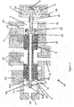
- the figure 1 shows a possible embodiment of a fluidic valve 50 of the invention.
- the fluidic valve 50 comprises a hollow valve body 20 comprising an inlet 22, two outlets 23 and a first communication 21 to a first pressure, for example a high pressure HP.
- the first communication 21 includes a fixed restriction 30.
- the fluidic valve 50 further comprises an actuator 40 located at least partially in the hollow of the hollow valve body and comprising a movable driver 41.
- the actuator 40 is a solenoid electric actuator and the driver 41 is ferromagnetic.
- the actuator 40 may be another type of actuator.
- the fluidic valve 50 further comprises a valve member 5 movable in the valve body 20.
- the member 5 allows at least partially to seal a passage between the inlet 22 and one of the two outlets 23.
- the valve member 5 at least partially defines a first 1 and a second 2 cavities located on either side of the valve member 5, in the hollow of the valve body 20.
- the first communication 21 is preferably connected fluidly to the first cavity 1.
- the first communication 21 is preferably at least partially in the valve body 20.
- the valve member 5 comprises a longitudinal hole 46 placing in direct or indirect fluidic communication the first 1 and second 2 cavities when it is not closed.
- the longitudinal hole 46 preferably opens through a first opening to the first cavity 1 or in the first cavity 1.
- the driver 41 is able to close at least partially the first opening of the longitudinal hole 46.
- the driver 41 is preferably located at least partially in the first cavity 1 .
- the valve member 5 comprises a recess 51 receiving a part of the driver 41, in particular the part of the driver 41 which makes it possible to close the first opening of the longitudinal hole 46.
- a wall 52 of the recess 51 is arranged to at least partially limit a displacement of the driver 41.
- the recess 51 is in fluid communication with the first cavity 1, so that the closure or the release of the first opening of the longitudinal hole 46 by the driver 41 influences the pressure in the recess 51 of the valve member 5 and therefore the pressure in the first cavity 1.
- valve 50 is arranged so that the driver 41 can drive the wall 52 and thus the valve member 5 towards the first cavity 1.
- the second cavity 2 is fluidly connected to a second pressure, for example an external BP pressure, with the aid of a second communication 26.
- a second pressure for example an external BP pressure
- the second communication 26 allows the second pressure to prevail in the second cavity 2.
- the fluidic valve 50 further comprises a third cavity 71 fluidly connected to a third pressure, for example an external HP pressure, with the aid of a third communication 27.
- a third pressure for example an external HP pressure
- the third communication 27 allows the third pressure to prevail in the third cavity 71.
- the third cavity 71 is preferably located in the hollow of the valve body 20.
- the fluidic valve 50 further comprises a piston 60 having a first portion 60a and a second portion 60b.
- the first part 60a being fixed to the valve member 5 in the second cavity 2.
- the second part 60b is situated at least partially in the third cavity 71.
- the first part 60a of the piston 60 is wider than the second part 60b of the piston 60.
- the piston 60 slides in a fifth communication 29 between the second 2 and the third 71 cavities.
- the piston 60 is preferably immersed.
- the first part 60a of the piston 60 is fixed to the valve member 50 around a second opening of the longitudinal hole 46 and is pierced with channels 61 putting in fluid communication the second cavity 2 and the longitudinal hole 46. This allows the forces resulting from the pressures on the piston to be aligned with the left-right movement of the valve member 5 and the pressure in the second cavity 2 also reigns in the longitudinal hole 46.
- the second portion 60b of the piston 60 has a surface portion at least partially perpendicular to the sliding direction of the piston 60. This surface portion is located in the third cavity and faces a direction opposite to the direction of the second cavity. In other words, this surface portion is arranged so that the piston 60 can be pushed towards the second cavity 2 by the pressure prevailing in the third cavity 71.
- the fluidic valve 50 further comprises a fourth cavity 72, preferably located in the recess of the valve body 20.
- the fourth cavity 72 is fluidly connected to the first cavity 1 via a conduit 47 in which part of the driver 41 can slide.
- the fourth cavity 72 is fluidly connected to a fourth pressure, for example an external BP pressure, by means of a fourth communication 28.
- the fourth communication 28 allows the fourth pressure to prevail in the fourth cavity 72.
- the fluidic valve 50 comprises a spring 9 connecting the driver 41 to a wall located opposite the pilot 41 relative to the valve member 5.
- the spring 9 can connect the driver 41 to a wall of the fourth cavity 71.
- the spring 9 can connect the driver 41 to a wall of the hollow of the valve body 20.
- the fluidic valve 50 can operate in the following manner.
- the force pushing the valve member 5 towards the right comes from (i) the force due to the pressure HP prevailing in the third cavity 71 and acting on the second portion 60b of the piston 60, and (ii) the force due to the BP pressure prevailing in the second cavity 2 and acting on the first portion 60a of the piston 60 and on the valve member 5.
- the position of the valve member 5 is thus determined by the balance between the forces exerted to the left at the level of the first cavity 1 and to the right at the level of the second cavity 2.
- first communication 21 and the third communication 27 are connected to the same external pressure, because if it changes, the pressures in the first cavity 1 and the third cavity 71 change in the same direction.
- the forces to the left and right also increase in the same direction and the position of the valve member 5 is only slightly influenced by this increase in external pressure.
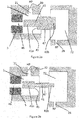
- the figure 2a illustrates the driver 41 according to a first embodiment of the pilot 41.
- the figure 2b illustrates the driver 41 according to a second embodiment of the pilot 41.
- the Figure 2c illustrates the driver 41 according to a third embodiment of the driver 41.
- These three embodiments of the driver 41 can be implemented in a fluidic valve 50 according to one embodiment of the invention.
- These three embodiments of the driver 41 may be implemented in another fluidic valve 50, for example a mechanical feedback fluidic valve, a hydraulic feedback fluidic valve or any other type of fluidic valve.
- the three embodiments of the driver 41 described herein are compatible with the fluidic valves described in the patent application. EP16179250 entitled "fluidic valve".
- the driver 41 comprises a first portion 41a located at least partially in the first cavity 1 and a second portion 41b located partially in the first cavity 1, partially in the conduit 47 and partially in the fourth cavity 72.
- the first part 41 a is preferentially narrower than the second part 41b.
- the driver 41 comprises in the first cavity 1 a surface 45 facing the valve member 5. The pressure in the first cavity 1 pushes on this surface 45 in the opposite direction of the valve member 5, opposing the closing of the first opening of the longitudinal conduit 46.
- the driver 41 according to the first embodiment of the driver 41 is arranged to undergo from a fluid present in the first cavity 1 a force directed towards the fourth cavity 72, that is to say in the opposite direction to the valve member 5.
- the first portion 41 is adapted to at least partially closing the first opening of the longitudinal hole 46.
- the driver 41 comprises a first portion 41a located at least partially in the first cavity 1 and a second portion 41b located partially in the first cavity 1, partially in the conduit 47 and partially in the fourth cavity 72.
- the first part 41 a is preferentially wider than the second part 41 b.
- the driver 41 comprises in the first cavity 1 a surface 45 facing away from the valve member 5. The pressure in the first cavity 1 pushes on this surface 45 in the direction of the valve member 5, favoring the closure of the first opening of the longitudinal duct 46.
- the pilot 41 according to the second embodiment of the pilot 41 is arranged to undergo from a fluid present in the first cavity 1 a force directed towards the member valve 5.
- the first part 41a is able to close at least partially the first opening of the longitudinal hole 46.
- the fluidic valve comprising the driver 41 according to the second embodiment of the driver 41 is therefore particularly reactive and may be said to be "unstable".
- the pilot 41 does not include several parts of different diameters joining in the first cavity 1.
- the pressure in the first cavity 1 therefore has no great influence on the movement of the driver 41.
- the pilot 41 according to the third embodiment of the driver 41 is arranged not to be subjected from a fluid present in the first cavity 1 of force directed towards the valve member 5 or opposite the valve member 5.
- the fluidic valve comprising the driver 41 according to the third embodiment of the driver 41 is therefore particularly balanced.
- driver 41 The three illustrated embodiments of the driver 41 are only examples, and one skilled in the art would understand that the shape of the driver 41 and the arrangement thereof in the fluidic valve 50 may be different to achieve the desired effect. stability (first embodiment of the driver 41), instability (second embodiment of the driver 41), or equilibrium (third embodiment of the driver 41).
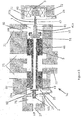
- the figure 3 is a sectional view of a fluidic valve 50 according to a possible embodiment of the invention.
- the fluidic valve 50 comprises a pilot 41 according to the second embodiment of the pilot 41.
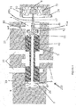
- the figure 4 is a sectional view of a fluidic valve 100 with mechanical feedback.
- the fluidic valve 100 with mechanical feedback illustrated comprises a pilot 41 according to the second embodiment of the pilot 41.
- the invention relates to a fluidic valve 50 comprising a valve member 5 located between a first 1 and a second 2 cavities and an actuator 40 comprising a driver 41.
- the valve member 5 moves through at the equilibrium between the pressures prevailing in the first 1 and second 2 cavities.
- the valve member 5 comprises a longitudinal hole 46 which can be obstructed by the driver 41, so as to modify the pressure in the first cavity 1 and the force exerted to the left on the valve member 5.
- the member valve 5 is attached to a piston 60, one end of which is located in a third cavity 71. The force exerted on the valve member 5 is determined by the pressures prevailing in the different cavities.
Landscapes
- Engineering & Computer Science (AREA)
- General Engineering & Computer Science (AREA)
- Mechanical Engineering (AREA)
- Fluid-Driven Valves (AREA)
- Multiple-Way Valves (AREA)
Applications Claiming Priority (1)
| Application Number | Priority Date | Filing Date | Title |
|---|---|---|---|
| BE2016/5728A BE1024622B1 (fr) | 2016-09-30 | 2016-09-30 | Vanne fluidique |
Publications (2)
| Publication Number | Publication Date |
|---|---|
| EP3301335A1 true EP3301335A1 (de) | 2018-04-04 |
| EP3301335B1 EP3301335B1 (de) | 2019-07-17 |
Family
ID=57132932
Family Applications (1)
| Application Number | Title | Priority Date | Filing Date |
|---|---|---|---|
| EP17189612.9A Active EP3301335B1 (de) | 2016-09-30 | 2017-09-06 | Flüssigkeitsventil |
Country Status (7)
| Country | Link |
|---|---|
| US (1) | US10760707B2 (de) |
| EP (1) | EP3301335B1 (de) |
| CN (1) | CN107883014B (de) |
| BE (1) | BE1024622B1 (de) |
| BR (1) | BR102017019461A2 (de) |
| CA (1) | CA2976757A1 (de) |
| RU (1) | RU2017133523A (de) |
Families Citing this family (9)
| Publication number | Priority date | Publication date | Assignee | Title |
|---|---|---|---|---|
| BE1026153B1 (fr) * | 2018-03-28 | 2019-10-29 | Safran Aero Boosters S.A. | Vanne fluidique |
| US11060621B2 (en) * | 2018-08-27 | 2021-07-13 | Facebook Technologies, Llc | Electromagnetically actuated fluidic-device valve apparatuses, systems, and methods |
| US10838493B2 (en) * | 2018-08-27 | 2020-11-17 | Facebook Technologies, Llc | Pressure actuated fluidic-device valve apparatuses, systems, and methods |
| BE1027205A9 (fr) * | 2019-04-17 | 2020-11-23 | Safran Aero Boosters Sa | Vanne fluidique passive de répartition de débits fixes |
| CN111853281A (zh) * | 2019-04-29 | 2020-10-30 | 华帝股份有限公司 | 一种防冻水阀及具有该防冻水阀的冷凝热水器 |
| EP3757433A1 (de) * | 2019-06-28 | 2020-12-30 | HUSCO Automotive Holdings LLC | Systeme und verfahren für ein steuerventil mit einer zwischenposition |
| CN110630805B (zh) * | 2019-09-26 | 2021-01-01 | 长安大学 | 一种航空发动机快速电磁阀系统及其控制方法 |
| CN113915184B (zh) * | 2021-09-13 | 2024-05-03 | 烟台艾迪液压科技有限公司 | 一种具有换向节流功能的平衡阀 |
| BE1030919B1 (fr) * | 2022-09-28 | 2024-04-30 | Safran Aero Boosters | Electrovanne et équipement avec l’électrovanne |
Citations (9)
| Publication number | Priority date | Publication date | Assignee | Title |
|---|---|---|---|---|
| US3722547A (en) * | 1970-10-21 | 1973-03-27 | Schneider Co Optische Werke | Pilot valve |
| US4245671A (en) * | 1976-08-26 | 1981-01-20 | Shoketsu Kinzoku Kogyo Kabushiki Kaisha | Solenoid pilot operated valve |
| GB2304839A (en) * | 1995-09-06 | 1997-03-26 | Rover Group | Coupling cap for vacuum bleeding equipment for a vehicle hydraulic brake system |
| GB2343935A (en) | 1998-11-23 | 2000-05-24 | Amot Controls Corp | Multi-configuration pilot valve |
| US20090224192A1 (en) * | 2008-03-04 | 2009-09-10 | Keihin Corporation | Electromagnetic spool valve |
| US20100301248A1 (en) * | 2008-06-27 | 2010-12-02 | Aisin Aw Co., Ltd. | Solenoid valve |
| EP2503201A1 (de) * | 2011-03-22 | 2012-09-26 | Incova Technologies, Inc. | Hydraulikventilanordnung mit Ringklappenventilelement |
| US20130312843A1 (en) * | 2012-05-24 | 2013-11-28 | Honeywell International Inc. | Pressure and flow altitude compensated shutoff valve |
| EP3128215A1 (de) * | 2015-08-03 | 2017-02-08 | Safran Aero Boosters SA | Flüssigkeitsventil |
Family Cites Families (6)
| Publication number | Priority date | Publication date | Assignee | Title |
|---|---|---|---|---|
| US4313468A (en) * | 1977-07-13 | 1982-02-02 | Dynex/Rivett Inc. | Servo valve |
| JP3375564B2 (ja) * | 1999-04-27 | 2003-02-10 | エスエムシー株式会社 | 倍力駆動パイロット形電磁弁 |
| IT1311060B1 (it) * | 1999-12-14 | 2002-02-28 | Bucher Hidroirma S P A | Valvola di controllo direzionale. |
| JP4306519B2 (ja) * | 2003-09-29 | 2009-08-05 | アイシン・エィ・ダブリュ株式会社 | 圧力制御弁 |
| DE102010005229A1 (de) * | 2010-01-21 | 2011-07-28 | Hydac Fluidtechnik GmbH, 66280 | Ventilvorrichtung |
| JP5588906B2 (ja) * | 2011-03-30 | 2014-09-10 | アズビル株式会社 | パイロットリレー |
-
2016
- 2016-09-30 BE BE2016/5728A patent/BE1024622B1/fr active IP Right Grant
-
2017
- 2017-08-16 CA CA2976757A patent/CA2976757A1/fr not_active Abandoned
- 2017-09-06 EP EP17189612.9A patent/EP3301335B1/de active Active
- 2017-09-12 BR BR102017019461-2A patent/BR102017019461A2/pt not_active IP Right Cessation
- 2017-09-27 RU RU2017133523A patent/RU2017133523A/ru not_active Application Discontinuation
- 2017-09-28 CN CN201710901336.9A patent/CN107883014B/zh active Active
- 2017-09-29 US US15/721,356 patent/US10760707B2/en active Active
Patent Citations (9)
| Publication number | Priority date | Publication date | Assignee | Title |
|---|---|---|---|---|
| US3722547A (en) * | 1970-10-21 | 1973-03-27 | Schneider Co Optische Werke | Pilot valve |
| US4245671A (en) * | 1976-08-26 | 1981-01-20 | Shoketsu Kinzoku Kogyo Kabushiki Kaisha | Solenoid pilot operated valve |
| GB2304839A (en) * | 1995-09-06 | 1997-03-26 | Rover Group | Coupling cap for vacuum bleeding equipment for a vehicle hydraulic brake system |
| GB2343935A (en) | 1998-11-23 | 2000-05-24 | Amot Controls Corp | Multi-configuration pilot valve |
| US20090224192A1 (en) * | 2008-03-04 | 2009-09-10 | Keihin Corporation | Electromagnetic spool valve |
| US20100301248A1 (en) * | 2008-06-27 | 2010-12-02 | Aisin Aw Co., Ltd. | Solenoid valve |
| EP2503201A1 (de) * | 2011-03-22 | 2012-09-26 | Incova Technologies, Inc. | Hydraulikventilanordnung mit Ringklappenventilelement |
| US20130312843A1 (en) * | 2012-05-24 | 2013-11-28 | Honeywell International Inc. | Pressure and flow altitude compensated shutoff valve |
| EP3128215A1 (de) * | 2015-08-03 | 2017-02-08 | Safran Aero Boosters SA | Flüssigkeitsventil |
Also Published As
| Publication number | Publication date |
|---|---|
| US20180094745A1 (en) | 2018-04-05 |
| CN107883014B (zh) | 2020-12-15 |
| RU2017133523A (ru) | 2019-03-27 |
| BE1024622B1 (fr) | 2018-05-24 |
| CA2976757A1 (fr) | 2018-03-30 |
| BR102017019461A2 (pt) | 2018-05-02 |
| US10760707B2 (en) | 2020-09-01 |
| EP3301335B1 (de) | 2019-07-17 |
| CN107883014A (zh) | 2018-04-06 |
| BE1024622A1 (fr) | 2018-04-26 |
Similar Documents
| Publication | Publication Date | Title |
|---|---|---|
| EP3301335B1 (de) | Flüssigkeitsventil | |
| EP3128215B1 (de) | Flüssigkeitsventil | |
| EP0192580A1 (de) | Flüssigkeitsdruckverstärker | |
| EP2778364A1 (de) | Steuervorrichtung der Einspeisung einer Flüssigkeit in ein System | |
| FR3032244A1 (fr) | Valve de regulation de debit. | |
| EP2006587B1 (de) | Dichtungsventilsystem | |
| EP0396479B1 (de) | Hahn mit Kugelküken | |
| EP0009749B1 (de) | Druckregelventil mit 3 oder 4 Druckwerten | |
| FR3079879A1 (fr) | Vanne de decharge a ouverture regulee | |
| EP3775577B1 (de) | Flüssigkeitsventil | |
| EP3446008B1 (de) | Ventilkolben für kraftstoffsystem eines flugzeugmotors | |
| EP3446009B1 (de) | Ventil für kraftstoffsystem eines flugzeugmotors | |
| BE1027205A9 (fr) | Vanne fluidique passive de répartition de débits fixes | |
| FR3071299B1 (fr) | Vanne thermostatique pour vehicule automobile | |
| EP3098403A1 (de) | Vorrichtung zur steuerung der zufuhr einer unter druck stehenden flüssigkeit | |
| FR2552514A1 (fr) | Amortisseur du type fluidique | |
| EP0664500B1 (de) | Druckregelservoventil | |
| EP4118344B1 (de) | Servoventil mit linearantrieb und mechanischer rückkopplung | |
| EP3477415B1 (de) | Thermostatventil | |
| EP2171329B1 (de) | Elektroventil zur proportionalen einstellung eines gegendruckflusses | |
| EP0434531A1 (de) | Einrichtung zur automatischen Bewegungsumkehr eines doppelt wirkenden Hydraulikstellgliedes | |
| FR3079875A1 (fr) | Dispositif de decharge de turbomachine comportant une vanne | |
| EP0055187A1 (de) | Regulationsventil und Pilotsteuerventil | |
| FR2475484A1 (fr) | Regulateur de pression jumele pour deux circuits, pour systemes de freinage hydraulique | |
| FR2705424A1 (fr) | Clapet anti retour avec limiteur de débit. |
Legal Events
| Date | Code | Title | Description |
|---|---|---|---|
| PUAI | Public reference made under article 153(3) epc to a published international application that has entered the european phase |
Free format text: ORIGINAL CODE: 0009012 |
|
| STAA | Information on the status of an ep patent application or granted ep patent |
Free format text: STATUS: THE APPLICATION HAS BEEN PUBLISHED |
|
| AK | Designated contracting states |
Kind code of ref document: A1 Designated state(s): AL AT BE BG CH CY CZ DE DK EE ES FI FR GB GR HR HU IE IS IT LI LT LU LV MC MK MT NL NO PL PT RO RS SE SI SK SM TR |
|
| AX | Request for extension of the european patent |
Extension state: BA ME |
|
| RIN1 | Information on inventor provided before grant (corrected) |
Inventor name: FRIPPIAT, CEDRIC Inventor name: PAULUS, NICOLAS Inventor name: BOMAL, JEAN-CHRISTIAN |
|
| STAA | Information on the status of an ep patent application or granted ep patent |
Free format text: STATUS: REQUEST FOR EXAMINATION WAS MADE |
|
| 17P | Request for examination filed |
Effective date: 20181002 |
|
| RBV | Designated contracting states (corrected) |
Designated state(s): AL AT BE BG CH CY CZ DE DK EE ES FI FR GB GR HR HU IE IS IT LI LT LU LV MC MK MT NL NO PL PT RO RS SE SI SK SM TR |
|
| GRAJ | Information related to disapproval of communication of intention to grant by the applicant or resumption of examination proceedings by the epo deleted |
Free format text: ORIGINAL CODE: EPIDOSDIGR1 |
|
| STAA | Information on the status of an ep patent application or granted ep patent |
Free format text: STATUS: GRANT OF PATENT IS INTENDED |
|
| GRAP | Despatch of communication of intention to grant a patent |
Free format text: ORIGINAL CODE: EPIDOSNIGR1 |
|
| RIC1 | Information provided on ipc code assigned before grant |
Ipc: F16K 11/07 20060101ALI20190128BHEP Ipc: F16K 31/42 20060101ALI20190128BHEP Ipc: F16K 31/40 20060101AFI20190128BHEP Ipc: B64D 47/00 20060101ALI20190128BHEP Ipc: F15B 13/04 20060101ALI20190128BHEP |
|
| INTG | Intention to grant announced |
Effective date: 20190301 |
|
| RIN1 | Information on inventor provided before grant (corrected) |
Inventor name: FRIPPIAT, CEDRIC Inventor name: PAULUS, NICOLAS Inventor name: BOMAL, JEAN-CHRISTIAN |
|
| GRAS | Grant fee paid |
Free format text: ORIGINAL CODE: EPIDOSNIGR3 |
|
| GRAA | (expected) grant |
Free format text: ORIGINAL CODE: 0009210 |
|
| STAA | Information on the status of an ep patent application or granted ep patent |
Free format text: STATUS: THE PATENT HAS BEEN GRANTED |
|
| AK | Designated contracting states |
Kind code of ref document: B1 Designated state(s): AL AT BE BG CH CY CZ DE DK EE ES FI FR GB GR HR HU IE IS IT LI LT LU LV MC MK MT NL NO PL PT RO RS SE SI SK SM TR |
|
| REG | Reference to a national code |
Ref country code: GB Ref legal event code: FG4D Free format text: NOT ENGLISH |
|
| REG | Reference to a national code |
Ref country code: CH Ref legal event code: EP |
|
| REG | Reference to a national code |
Ref country code: DE Ref legal event code: R096 Ref document number: 602017005327 Country of ref document: DE |
|
| REG | Reference to a national code |
Ref country code: IE Ref legal event code: FG4D Free format text: LANGUAGE OF EP DOCUMENT: FRENCH |
|
| REG | Reference to a national code |
Ref country code: AT Ref legal event code: REF Ref document number: 1156161 Country of ref document: AT Kind code of ref document: T Effective date: 20190815 |
|
| REG | Reference to a national code |
Ref country code: NL Ref legal event code: MP Effective date: 20190717 |
|
| REG | Reference to a national code |
Ref country code: LT Ref legal event code: MG4D |
|
| REG | Reference to a national code |
Ref country code: AT Ref legal event code: MK05 Ref document number: 1156161 Country of ref document: AT Kind code of ref document: T Effective date: 20190717 |
|
| PG25 | Lapsed in a contracting state [announced via postgrant information from national office to epo] |
Ref country code: AT Free format text: LAPSE BECAUSE OF FAILURE TO SUBMIT A TRANSLATION OF THE DESCRIPTION OR TO PAY THE FEE WITHIN THE PRESCRIBED TIME-LIMIT Effective date: 20190717 Ref country code: NL Free format text: LAPSE BECAUSE OF FAILURE TO SUBMIT A TRANSLATION OF THE DESCRIPTION OR TO PAY THE FEE WITHIN THE PRESCRIBED TIME-LIMIT Effective date: 20190717 Ref country code: PT Free format text: LAPSE BECAUSE OF FAILURE TO SUBMIT A TRANSLATION OF THE DESCRIPTION OR TO PAY THE FEE WITHIN THE PRESCRIBED TIME-LIMIT Effective date: 20191118 Ref country code: BG Free format text: LAPSE BECAUSE OF FAILURE TO SUBMIT A TRANSLATION OF THE DESCRIPTION OR TO PAY THE FEE WITHIN THE PRESCRIBED TIME-LIMIT Effective date: 20191017 Ref country code: SE Free format text: LAPSE BECAUSE OF FAILURE TO SUBMIT A TRANSLATION OF THE DESCRIPTION OR TO PAY THE FEE WITHIN THE PRESCRIBED TIME-LIMIT Effective date: 20190717 Ref country code: NO Free format text: LAPSE BECAUSE OF FAILURE TO SUBMIT A TRANSLATION OF THE DESCRIPTION OR TO PAY THE FEE WITHIN THE PRESCRIBED TIME-LIMIT Effective date: 20191017 Ref country code: HR Free format text: LAPSE BECAUSE OF FAILURE TO SUBMIT A TRANSLATION OF THE DESCRIPTION OR TO PAY THE FEE WITHIN THE PRESCRIBED TIME-LIMIT Effective date: 20190717 Ref country code: LT Free format text: LAPSE BECAUSE OF FAILURE TO SUBMIT A TRANSLATION OF THE DESCRIPTION OR TO PAY THE FEE WITHIN THE PRESCRIBED TIME-LIMIT Effective date: 20190717 Ref country code: FI Free format text: LAPSE BECAUSE OF FAILURE TO SUBMIT A TRANSLATION OF THE DESCRIPTION OR TO PAY THE FEE WITHIN THE PRESCRIBED TIME-LIMIT Effective date: 20190717 |
|
| PG25 | Lapsed in a contracting state [announced via postgrant information from national office to epo] |
Ref country code: RS Free format text: LAPSE BECAUSE OF FAILURE TO SUBMIT A TRANSLATION OF THE DESCRIPTION OR TO PAY THE FEE WITHIN THE PRESCRIBED TIME-LIMIT Effective date: 20190717 Ref country code: IS Free format text: LAPSE BECAUSE OF FAILURE TO SUBMIT A TRANSLATION OF THE DESCRIPTION OR TO PAY THE FEE WITHIN THE PRESCRIBED TIME-LIMIT Effective date: 20191117 Ref country code: ES Free format text: LAPSE BECAUSE OF FAILURE TO SUBMIT A TRANSLATION OF THE DESCRIPTION OR TO PAY THE FEE WITHIN THE PRESCRIBED TIME-LIMIT Effective date: 20190717 Ref country code: GR Free format text: LAPSE BECAUSE OF FAILURE TO SUBMIT A TRANSLATION OF THE DESCRIPTION OR TO PAY THE FEE WITHIN THE PRESCRIBED TIME-LIMIT Effective date: 20191018 Ref country code: AL Free format text: LAPSE BECAUSE OF FAILURE TO SUBMIT A TRANSLATION OF THE DESCRIPTION OR TO PAY THE FEE WITHIN THE PRESCRIBED TIME-LIMIT Effective date: 20190717 Ref country code: LV Free format text: LAPSE BECAUSE OF FAILURE TO SUBMIT A TRANSLATION OF THE DESCRIPTION OR TO PAY THE FEE WITHIN THE PRESCRIBED TIME-LIMIT Effective date: 20190717 |
|
| PG25 | Lapsed in a contracting state [announced via postgrant information from national office to epo] |
Ref country code: TR Free format text: LAPSE BECAUSE OF FAILURE TO SUBMIT A TRANSLATION OF THE DESCRIPTION OR TO PAY THE FEE WITHIN THE PRESCRIBED TIME-LIMIT Effective date: 20190717 |
|
| PG25 | Lapsed in a contracting state [announced via postgrant information from national office to epo] |
Ref country code: DK Free format text: LAPSE BECAUSE OF FAILURE TO SUBMIT A TRANSLATION OF THE DESCRIPTION OR TO PAY THE FEE WITHIN THE PRESCRIBED TIME-LIMIT Effective date: 20190717 Ref country code: IT Free format text: LAPSE BECAUSE OF FAILURE TO SUBMIT A TRANSLATION OF THE DESCRIPTION OR TO PAY THE FEE WITHIN THE PRESCRIBED TIME-LIMIT Effective date: 20190717 Ref country code: EE Free format text: LAPSE BECAUSE OF FAILURE TO SUBMIT A TRANSLATION OF THE DESCRIPTION OR TO PAY THE FEE WITHIN THE PRESCRIBED TIME-LIMIT Effective date: 20190717 Ref country code: RO Free format text: LAPSE BECAUSE OF FAILURE TO SUBMIT A TRANSLATION OF THE DESCRIPTION OR TO PAY THE FEE WITHIN THE PRESCRIBED TIME-LIMIT Effective date: 20190717 Ref country code: PL Free format text: LAPSE BECAUSE OF FAILURE TO SUBMIT A TRANSLATION OF THE DESCRIPTION OR TO PAY THE FEE WITHIN THE PRESCRIBED TIME-LIMIT Effective date: 20190717 |
|
| PG25 | Lapsed in a contracting state [announced via postgrant information from national office to epo] |
Ref country code: SK Free format text: LAPSE BECAUSE OF FAILURE TO SUBMIT A TRANSLATION OF THE DESCRIPTION OR TO PAY THE FEE WITHIN THE PRESCRIBED TIME-LIMIT Effective date: 20190717 Ref country code: MC Free format text: LAPSE BECAUSE OF FAILURE TO SUBMIT A TRANSLATION OF THE DESCRIPTION OR TO PAY THE FEE WITHIN THE PRESCRIBED TIME-LIMIT Effective date: 20190717 Ref country code: CZ Free format text: LAPSE BECAUSE OF FAILURE TO SUBMIT A TRANSLATION OF THE DESCRIPTION OR TO PAY THE FEE WITHIN THE PRESCRIBED TIME-LIMIT Effective date: 20190717 Ref country code: SM Free format text: LAPSE BECAUSE OF FAILURE TO SUBMIT A TRANSLATION OF THE DESCRIPTION OR TO PAY THE FEE WITHIN THE PRESCRIBED TIME-LIMIT Effective date: 20190717 Ref country code: IS Free format text: LAPSE BECAUSE OF FAILURE TO SUBMIT A TRANSLATION OF THE DESCRIPTION OR TO PAY THE FEE WITHIN THE PRESCRIBED TIME-LIMIT Effective date: 20200224 |
|
| REG | Reference to a national code |
Ref country code: DE Ref legal event code: R097 Ref document number: 602017005327 Country of ref document: DE |
|
| PLBE | No opposition filed within time limit |
Free format text: ORIGINAL CODE: 0009261 |
|
| STAA | Information on the status of an ep patent application or granted ep patent |
Free format text: STATUS: NO OPPOSITION FILED WITHIN TIME LIMIT |
|
| PG2D | Information on lapse in contracting state deleted |
Ref country code: IS |
|
| PG25 | Lapsed in a contracting state [announced via postgrant information from national office to epo] |
Ref country code: IE Free format text: LAPSE BECAUSE OF NON-PAYMENT OF DUE FEES Effective date: 20190906 Ref country code: LU Free format text: LAPSE BECAUSE OF NON-PAYMENT OF DUE FEES Effective date: 20190906 |
|
| 26N | No opposition filed |
Effective date: 20200603 |
|
| PG25 | Lapsed in a contracting state [announced via postgrant information from national office to epo] |
Ref country code: SI Free format text: LAPSE BECAUSE OF FAILURE TO SUBMIT A TRANSLATION OF THE DESCRIPTION OR TO PAY THE FEE WITHIN THE PRESCRIBED TIME-LIMIT Effective date: 20190717 |
|
| REG | Reference to a national code |
Ref country code: CH Ref legal event code: PL |
|
| PG25 | Lapsed in a contracting state [announced via postgrant information from national office to epo] |
Ref country code: CY Free format text: LAPSE BECAUSE OF FAILURE TO SUBMIT A TRANSLATION OF THE DESCRIPTION OR TO PAY THE FEE WITHIN THE PRESCRIBED TIME-LIMIT Effective date: 20190717 |
|
| PG25 | Lapsed in a contracting state [announced via postgrant information from national office to epo] |
Ref country code: MT Free format text: LAPSE BECAUSE OF FAILURE TO SUBMIT A TRANSLATION OF THE DESCRIPTION OR TO PAY THE FEE WITHIN THE PRESCRIBED TIME-LIMIT Effective date: 20190717 Ref country code: HU Free format text: LAPSE BECAUSE OF FAILURE TO SUBMIT A TRANSLATION OF THE DESCRIPTION OR TO PAY THE FEE WITHIN THE PRESCRIBED TIME-LIMIT; INVALID AB INITIO Effective date: 20170906 |
|
| PG25 | Lapsed in a contracting state [announced via postgrant information from national office to epo] |
Ref country code: LI Free format text: LAPSE BECAUSE OF NON-PAYMENT OF DUE FEES Effective date: 20200930 Ref country code: CH Free format text: LAPSE BECAUSE OF NON-PAYMENT OF DUE FEES Effective date: 20200930 |
|
| PG25 | Lapsed in a contracting state [announced via postgrant information from national office to epo] |
Ref country code: MK Free format text: LAPSE BECAUSE OF FAILURE TO SUBMIT A TRANSLATION OF THE DESCRIPTION OR TO PAY THE FEE WITHIN THE PRESCRIBED TIME-LIMIT Effective date: 20190717 |
|
| PGFP | Annual fee paid to national office [announced via postgrant information from national office to epo] |
Ref country code: DE Payment date: 20250919 Year of fee payment: 9 |
|
| PGFP | Annual fee paid to national office [announced via postgrant information from national office to epo] |
Ref country code: BE Payment date: 20250919 Year of fee payment: 9 Ref country code: GB Payment date: 20250923 Year of fee payment: 9 |
|
| PGFP | Annual fee paid to national office [announced via postgrant information from national office to epo] |
Ref country code: FR Payment date: 20250923 Year of fee payment: 9 |