EP3301344B1 - Anschlussvorrichtung, die eine flexible muffe zum sammeln einer flüssigkeit im falle eines lecks oder aussickerns umfasst - Google Patents
Anschlussvorrichtung, die eine flexible muffe zum sammeln einer flüssigkeit im falle eines lecks oder aussickerns umfasst Download PDFInfo
- Publication number
- EP3301344B1 EP3301344B1 EP17190617.5A EP17190617A EP3301344B1 EP 3301344 B1 EP3301344 B1 EP 3301344B1 EP 17190617 A EP17190617 A EP 17190617A EP 3301344 B1 EP3301344 B1 EP 3301344B1
- Authority
- EP
- European Patent Office
- Prior art keywords
- orifice
- flexible sleeve
- flexible tube
- connection device
- circular wall
- Prior art date
- Legal status (The legal status is an assumption and is not a legal conclusion. Google has not performed a legal analysis and makes no representation as to the accuracy of the status listed.)
- Active
Links
Images

Classifications
-
- F—MECHANICAL ENGINEERING; LIGHTING; HEATING; WEAPONS; BLASTING
- F16—ENGINEERING ELEMENTS AND UNITS; GENERAL MEASURES FOR PRODUCING AND MAINTAINING EFFECTIVE FUNCTIONING OF MACHINES OR INSTALLATIONS; THERMAL INSULATION IN GENERAL
- F16L—PIPES; JOINTS OR FITTINGS FOR PIPES; SUPPORTS FOR PIPES, CABLES OR PROTECTIVE TUBING; MEANS FOR THERMAL INSULATION IN GENERAL
- F16L55/00—Devices or appurtenances for use in, or in connection with, pipes or pipe systems
- F16L55/16—Devices for covering leaks in pipes or hoses, e.g. hose-menders
- F16L55/168—Devices for covering leaks in pipes or hoses, e.g. hose-menders from outside the pipe
-
- F—MECHANICAL ENGINEERING; LIGHTING; HEATING; WEAPONS; BLASTING
- F16—ENGINEERING ELEMENTS AND UNITS; GENERAL MEASURES FOR PRODUCING AND MAINTAINING EFFECTIVE FUNCTIONING OF MACHINES OR INSTALLATIONS; THERMAL INSULATION IN GENERAL
- F16K—VALVES; TAPS; COCKS; ACTUATING-FLOATS; DEVICES FOR VENTING OR AERATING
- F16K27/00—Construction of housing; Use of materials therefor
- F16K27/12—Covers for housings
-
- F—MECHANICAL ENGINEERING; LIGHTING; HEATING; WEAPONS; BLASTING
- F16—ENGINEERING ELEMENTS AND UNITS; GENERAL MEASURES FOR PRODUCING AND MAINTAINING EFFECTIVE FUNCTIONING OF MACHINES OR INSTALLATIONS; THERMAL INSULATION IN GENERAL
- F16L—PIPES; JOINTS OR FITTINGS FOR PIPES; SUPPORTS FOR PIPES, CABLES OR PROTECTIVE TUBING; MEANS FOR THERMAL INSULATION IN GENERAL
- F16L55/00—Devices or appurtenances for use in, or in connection with, pipes or pipe systems
- F16L55/07—Arrangement or mounting of devices, e.g. valves, for venting or aerating or draining
-
- F—MECHANICAL ENGINEERING; LIGHTING; HEATING; WEAPONS; BLASTING
- F16—ENGINEERING ELEMENTS AND UNITS; GENERAL MEASURES FOR PRODUCING AND MAINTAINING EFFECTIVE FUNCTIONING OF MACHINES OR INSTALLATIONS; THERMAL INSULATION IN GENERAL
- F16L—PIPES; JOINTS OR FITTINGS FOR PIPES; SUPPORTS FOR PIPES, CABLES OR PROTECTIVE TUBING; MEANS FOR THERMAL INSULATION IN GENERAL
- F16L57/00—Protection of pipes or objects of similar shape against external or internal damage or wear
-
- G—PHYSICS
- G01—MEASURING; TESTING
- G01M—TESTING STATIC OR DYNAMIC BALANCE OF MACHINES OR STRUCTURES; TESTING OF STRUCTURES OR APPARATUS, NOT OTHERWISE PROVIDED FOR
- G01M3/00—Investigating fluid-tightness of structures
- G01M3/02—Investigating fluid-tightness of structures by using fluid or vacuum
- G01M3/26—Investigating fluid-tightness of structures by using fluid or vacuum by measuring rate of loss or gain of fluid, e.g. by pressure-responsive devices, by flow detectors
- G01M3/28—Investigating fluid-tightness of structures by using fluid or vacuum by measuring rate of loss or gain of fluid, e.g. by pressure-responsive devices, by flow detectors for pipes, cables or tubes; for pipe joints or seals; for valves ; for welds
- G01M3/2853—Investigating fluid-tightness of structures by using fluid or vacuum by measuring rate of loss or gain of fluid, e.g. by pressure-responsive devices, by flow detectors for pipes, cables or tubes; for pipe joints or seals; for valves ; for welds for pipe joints or seals
- G01M3/2861—Investigating fluid-tightness of structures by using fluid or vacuum by measuring rate of loss or gain of fluid, e.g. by pressure-responsive devices, by flow detectors for pipes, cables or tubes; for pipe joints or seals; for valves ; for welds for pipe joints or seals for pipe sections by testing its exterior surface
-
- F—MECHANICAL ENGINEERING; LIGHTING; HEATING; WEAPONS; BLASTING
- F16—ENGINEERING ELEMENTS AND UNITS; GENERAL MEASURES FOR PRODUCING AND MAINTAINING EFFECTIVE FUNCTIONING OF MACHINES OR INSTALLATIONS; THERMAL INSULATION IN GENERAL
- F16L—PIPES; JOINTS OR FITTINGS FOR PIPES; SUPPORTS FOR PIPES, CABLES OR PROTECTIVE TUBING; MEANS FOR THERMAL INSULATION IN GENERAL
- F16L2201/00—Special arrangements for pipe couplings
- F16L2201/30—Detecting leaks
Definitions
- the present application relates to a connecting device comprising a flexible sleeve for collecting a liquid in case of leakage or seepage.
- a connecting device comprising a flexible sleeve for collecting a liquid in case of leakage or seepage.
- a connecting device comprising a flexible sleeve for collecting a liquid in case of leakage or seepage.
- the first and second conduits have circular sections and have axes coincide.
- the longitudinal direction is parallel to the axis of the first conduit.
- a longitudinal plane contains the axis of the first conduit.
- a transverse plane is a plane perpendicular to the first conduit.
- the connecting device and the ducts are positioned inside rigid outer ducts to collect and drain to a given point the liquid in case of leakage at the connection device.
- a central wing box of an aircraft in which several connecting devices are positioned is sealed to collect the liquid in case of leakage at one of the connecting devices and to prevent the propagation of the liquid to other areas.
- This second embodiment makes it possible to eliminate the outer conduits and consequently to reduce the on-board weight.
- the aircraft in the event of seepage at one of the connecting devices, the aircraft must be stopped on the ground for repair.
- the present invention aims to overcome the disadvantages of the prior art.
- the flexible sleeve makes it possible to collect a liquid in the event of leakage or seepage at the junction zone between the first and second conduits and to prevent the liquid from spilling out of the flexible sleeve.
- the aircraft is not necessarily immobilized on the ground.
- the flexible sleeve forms a barrier to protect impurities the junction zone between the first and second conduits.
- the connecting device comprises a filling indicator.
- the flexible sleeve comprises a first orifice configured to communicate the inside of the flexible sleeve with the outside and the filling indicator comprises a deformable circular wall closing the first orifice, said deformable circular wall being movable between a inactive position in which the deformable circular wall is housed inside the flexible sleeve and an active position in which the deformable circular wall is deployed outside the flexible sleeve.
- the first orifice is positioned on a summit portion of the flexible sleeve.
- the deformable circular wall and / or a connection between the deformable circular wall and an edge of the first orifice have a mechanical strength configured to break in the event of significant leakage.
- the flexible sleeve comprises a second orifice configured to communicate the inside of the flexible sleeve with the outside, positioned in the lower part of the flexible sleeve.
- the second orifice is closed by a draining system configured to occupy a blocked state in which it prevents a flow of liquid through the second orifice and a passing state in which it allows a flow of liquid through the second orifice. orifice.
- the flexible sleeve comprises at least one bellows-shaped section.
- connection device 30 is shown between a first duct 32 and a second duct 34.
- the first and second ducts 32 and 34 form part of a fuel pipe of an aircraft.
- the invention is not limited to this application.
- connection device is dynamic. Thus, in operation, at least one of the ducts 32, 34 can move relative to the other duct.
- the first conduit 32 has a housing 36 at one of its ends and the second conduit 34 has at one of its ends a head 38 configured to be housed in the housing 36 of the first conduit 32 and a groove 40 which extends over the entire circumference of the outer surface of the head 38.
- the connecting device also comprises an annular seal 42 which is housed in the groove 40 and which is compressed between the groove 40 of the head 38 of the second conduit 34 and the wall of the housing 36 of the first conduit 32.
- the device according to the invention provides a seal to the liquid between the first conduit 32 and the flexible sleeve 46 as well as a liquid seal between the second conduit 34 and the flexible sleeve 46.
- the flexible sleeve 46 makes it possible to collect a liquid in the event of leakage or seepage at the junction zone 44 and to prevent the liquid from spilling out of the flexible sleeve 46. Another advantage, the flexible sleeve 46 protects impurities annular seal 42 and the housing wall 36 of the first conduit 32.
- the first and second clamping systems 52, 54 are positioned as close as possible to the junction zone 44.
- each clamping system 52, 54 is a clamping collar, for example made of plastic material.
- the flexible sleeve 46 is deformable to allow the first and second conduits 52, 54 to move relative to each other so that the connecting device is dynamic.
- the flexible sleeve 46 is made of a flexible material resistant to fuel, such as for example polytetrafluoroethylene or neoprene.
- the flexible sleeve 46 is distended between the first and second clamping systems 52, 54 to be able to collect a liquid in the event of leakage or seepage and to allow the first and second conduits 52, 54 to move relative to one another. other so that the connecting device is dynamic.
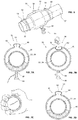
- the flexible sleeve 46 comprises at least one section in the form of a bellows. This configuration makes it possible to increase the capacity of the flexible sleeve 46 to deform and the storage volume of the liquid collected, as illustrated in FIG. Figure 4B .
- the flexible sleeve 46 comprises a filling indicator 56, as illustrated in FIGS. Figures 5A to 5B .
- this filling indicator 56 is configured to occupy a first state when the volume of liquid trapped between the flexible sleeve 46 and the first and second conduits 32, 34 is less than a given threshold and a second state when the volume of liquid is greater than or equal to the given threshold.
- the flexible sleeve 46 comprises a first orifice 58 which makes it possible to communicate the inside of the flexible sleeve 46 with the outside.
- the indicator filling member 56 comprises a deformable circular wall 60 closing the first orifice 58.
- the deformable circular wall 60 has a diameter greater than the diameter of the first orifice 58 and is connected to the periphery thereof.
- the first orifice 58 is positioned on the summit portion of the flexible sleeve 46 so that the deformable circular wall 60 is in contact with the gas (generally ambient air) present in the flexible sleeve 46 even in case of leakage.
- the gas generally ambient air
- This deformable circular wall 60 is movable between an inactive position (illustrated on the Figure 5A ) in which the deformable circular wall 60 is housed inside the flexible sleeve 46 and an active position (illustrated in FIG. Figure 5C ) in which the deformable circular wall 60 is deployed outside the flexible sleeve 46.
- the deformable circular wall 60 is positioned inside the flexible sleeve 46, which corresponds to the first state of the filling indicator 56.
- the liquid 62 In case of leakage, the liquid 62 accumulates inside the flexible sleeve 46, in the lower part. As long as the level of the liquid 62 is below the given threshold, the deformable circular wall 60 remains in its inactive position as illustrated by the Figure 5A because the pressure inside the flexible sleeve 46 is not sufficient to cause the displacement of the deformable circular wall 60 in its active position illustrated by the Figure 5C .
- the deformable circular wall 60 unfolds in its active position illustrated by the Figure 5C because the pressure inside the flexible sleeve 46 is sufficient to cause the displacement of the deformable circular wall 60 outside the flexible sleeve 46.
- the deformable circular wall 60 and / or the connection between the deformable circular wall 60 and the edge of the first orifice 58 have a mechanical strength configured to ensure a fuse function and to break in the event of a major leak.
- the flexible sleeve 46 comprises a second orifice 64 which makes it possible to communicate the inside of the flexible sleeve 46 with the outside, positioned in the lower part of the flexible sleeve 46 to obtain a complete emptying of the flexible sleeve 46.
- This second orifice 64 may be closed off by a plug or by a drainage system 66, such as for example a valve visible on the Figures 6, 7A, 7B and 7D .
- This drain system 66 is configured to occupy a blocked state in which it prevents a flow of liquid through the second port 64 and an on state in which it allows a flow of liquid through the second port 64.
- the fill indicator 56 and the drain system 66 are used to determine a flow rate of the leak.
- the emptying system 66 is in the on state to completely empty the flexible sleeve 46.
- the deformable circular wall 60 of the filling indicator 56 is repositioned inside the flexible sleeve 46 and the emptying system 66 is in the off state, as shown in FIG. Figure 7B .
- the duration is measured until the change of state of the filling indicator 46, corresponding to the output of the deformable circular wall 60 as illustrated in FIG. Figure 7D .
Landscapes
- Engineering & Computer Science (AREA)
- General Engineering & Computer Science (AREA)
- Mechanical Engineering (AREA)
- Physics & Mathematics (AREA)
- General Physics & Mathematics (AREA)
- Rigid Pipes And Flexible Pipes (AREA)
- Pipe Accessories (AREA)
- Infusion, Injection, And Reservoir Apparatuses (AREA)
Claims (6)
- Anschlussvorrichtung, welche eine erste Leitung (32), eine zweite Leitung (34) und einen Verbindungsbereich (44) zwischen der ersten und der zweiten Leitung (32, 34) umfasst, wobei die Anschlussvorrichtung außerdem umfasst:- eine flexible Muffe (46), welche ein erstes Ende (48), das dafür ausgelegt ist, einen Teil der ersten Leitung (32) zu bedecken, ein zweites Ende (50), das dafür ausgelegt ist, einen Teil der zweiten Leitung (34) zu bedecken, und eine erste Öffnung (58), die dafür ausgelegt ist, eine Verbindung des Inneren der flexiblen Muffe (46) mit der Außenseite herzustellen, aufweist,- ein erstes Klemmsystem (52), das dafür ausgelegt ist, das erste Ende (48) der flexiblen Muffe (46) um die erste Leitung (32) herum festzuklemmen,- ein zweites Klemmsystem (54), das dafür ausgelegt ist, das zweite Ende (50) der flexiblen Muffe (46) um die zweite Leitung (34) herum festzuklemmen,- wobei das erste und das zweite Klemmsystem (52, 54) beiderseits des Verbindungsbereichs (44) angeordnet sind, und- einen Füllanzeiger (56),
wobei die Vorrichtung dadurch gekennzeichnet ist, dass der Füllanzeiger (56) eine verformbare kreisförmige Wand (60) aufweist, welche die erste Öffnung (58) verschließt, wobei die verformbare kreisförmige Wand (60) zwischen einer inaktiven Position, in welcher die verformbare kreisförmige Wand (60) im Inneren der flexiblen Muffe (46) aufgenommen ist, und einer aktiven Position, in welcher die verformbare kreisförmige Wand (60) auf der Außenseite der flexiblen Muffe (46) ausgebreitet ist, beweglich ist. - Anschlussvorrichtung nach dem vorhergehenden Anspruch, dadurch gekennzeichnet, dass die erste Öffnung (58) auf einem Scheitelteil der flexiblen Muffe (46) positioniert ist.
- Anschlussvorrichtung nach einem der Ansprüche 1 bis 2, dadurch gekennzeichnet, dass die verformbare kreisförmige Wand (60) und/oder eine Verbindung zwischen der verformbaren kreisförmigen Wand (60) und einem Rand der ersten Öffnung (58) einen mechanischen Widerstand aufweist, der so bemessen ist, dass sie im Falle einer starken Leckage birst.
- Anschlussvorrichtung nach einem der vorhergehenden Ansprüche, dadurch gekennzeichnet, dass die flexible Muffe (46) eine zweite Öffnung (64), die dafür ausgelegt ist, eine Verbindung des Inneren der flexiblen Muffe (46) mit der Außenseite herzustellen, und im unteren Teil der flexiblen Muffe (46) positioniert ist, umfasst.
- Anschlussvorrichtung nach dem vorhergehenden Anspruch, dadurch gekennzeichnet, dass die zweite Öffnung (64) von einem Entleerungssystem (66) verschlossen wird, das dafür ausgelegt ist, einen blockierten Zustand, in welchem es ein Fließen von Flüssigkeit durch die zweite Öffnung (64) hindurch verhindert, und einen Durchgangszustand, in welchem es ein Fließen von Flüssigkeit durch die zweite Öffnung (64) hindurch ermöglicht, einzunehmen.
- Anschlussvorrichtung nach einem der vorhergehenden Ansprüche, dadurch gekennzeichnet, dass die flexible Muffe (46) wenigstens einen balgförmigen Abschnitt umfasst.
Applications Claiming Priority (1)
| Application Number | Priority Date | Filing Date | Title |
|---|---|---|---|
| FR1659318A FR3056673B1 (fr) | 2016-09-29 | 2016-09-29 | Dispositif de raccordement comprenant un manchon souple pour collecter un liquide en cas de fuite ou de suintement |
Publications (2)
| Publication Number | Publication Date |
|---|---|
| EP3301344A1 EP3301344A1 (de) | 2018-04-04 |
| EP3301344B1 true EP3301344B1 (de) | 2019-06-26 |
Family
ID=57583263
Family Applications (1)
| Application Number | Title | Priority Date | Filing Date |
|---|---|---|---|
| EP17190617.5A Active EP3301344B1 (de) | 2016-09-29 | 2017-09-12 | Anschlussvorrichtung, die eine flexible muffe zum sammeln einer flüssigkeit im falle eines lecks oder aussickerns umfasst |
Country Status (3)
| Country | Link |
|---|---|
| US (1) | US10415737B2 (de) |
| EP (1) | EP3301344B1 (de) |
| FR (1) | FR3056673B1 (de) |
Families Citing this family (6)
| Publication number | Priority date | Publication date | Assignee | Title |
|---|---|---|---|---|
| FR3082913B1 (fr) * | 2018-06-20 | 2022-01-21 | Airbus Operations Sas | Raccord permettant de relier deux portions d’un circuit d’air, dispositif de jonction comportant ledit raccord et circuit d’air d’un aeronef comportant ledit dispositif de jonction |
| US11002628B2 (en) * | 2018-09-20 | 2021-05-11 | Rosemount Inc. | Thermowell with primary seal verification |
| FR3091586B1 (fr) * | 2019-01-03 | 2021-04-30 | Protecto | Système de surveillance d’un appareil hydraulique, tel qu’un compteur d’eau, avec dispositif de détection d’une fuite d’eau sur l’appareil hydraulique |
| WO2022051585A1 (en) * | 2020-09-07 | 2022-03-10 | Chevron U.S.A. Inc. | Device and method for capturing leaks from a pipeline, valve or flange |
| US12590859B2 (en) * | 2023-08-30 | 2026-03-31 | Deere & Company | Fob geometry for leak detection in mobile equipment |
| CN117905924A (zh) * | 2024-02-24 | 2024-04-19 | 珠海吉泰克物理科技有限公司 | 一种排气阀 |
Family Cites Families (12)
| Publication number | Priority date | Publication date | Assignee | Title |
|---|---|---|---|---|
| US4295669A (en) * | 1977-04-11 | 1981-10-20 | Johns-Manville Corporation | Thermal insulation especially for pipe, flanges and fittings |
| GB2274919A (en) * | 1993-02-04 | 1994-08-10 | David Attree | Indicating leaks from pressure cylinders. |
| US5533760A (en) | 1994-06-23 | 1996-07-09 | Shell Oil Company | Method and device for containing fluids |
| DE29818853U1 (de) * | 1998-10-22 | 1999-01-07 | BRUGG Rohrsysteme GmbH, 31515 Wunstorf | Anschlußverbindung für ein Leitungsrohr für den Transport umweltgefährdender Medien |
| US6164345A (en) * | 2000-01-14 | 2000-12-26 | Matrix Service, Inc. | Flexible fluid containment system |
| US8561647B2 (en) * | 2008-03-07 | 2013-10-22 | The Gates Corporation | Safety and indicator apparatus systems and methods for high pressure conduits |
| DE202008003576U1 (de) * | 2008-03-13 | 2008-05-08 | V.A.T. Verbindungs- Und Anschlusstechnik Gmbh | Rückstandssammler |
| DE102008026596A1 (de) * | 2008-06-03 | 2009-12-10 | Linde Ag | Entleerungs- und Entlüftungsvorrichtung für einen Kompensator |
| FR2962548B1 (fr) * | 2010-07-08 | 2012-08-17 | Inst Francais Du Petrole | Procede de controle de l'integrite d'une conduite tubulaire flexible et dispositif pour sa mise en ?uvre |
| FR2973341B1 (fr) * | 2011-04-04 | 2013-12-06 | Airbus Operations Sas | Dispositif de raccordement d'un systeme de detection d'une fuite d'air a un manchon enveloppant un conduit d'air sous pression d'un aeronef |
| FR2977938B1 (fr) * | 2011-07-13 | 2014-04-11 | Airbus Operations Sas | Conduit d'air chaud sous pression d'un aeronef equipe d'un dispositif de detection d'une fuite |
| US10001232B2 (en) * | 2015-03-13 | 2018-06-19 | The Boeing Company | Systems and methods for duct protection |
-
2016
- 2016-09-29 FR FR1659318A patent/FR3056673B1/fr not_active Expired - Fee Related
-
2017
- 2017-09-12 EP EP17190617.5A patent/EP3301344B1/de active Active
- 2017-09-26 US US15/716,064 patent/US10415737B2/en active Active
Non-Patent Citations (1)
| Title |
|---|
| None * |
Also Published As
| Publication number | Publication date |
|---|---|
| FR3056673B1 (fr) | 2019-03-29 |
| EP3301344A1 (de) | 2018-04-04 |
| US20180087707A1 (en) | 2018-03-29 |
| FR3056673A1 (fr) | 2018-03-30 |
| US10415737B2 (en) | 2019-09-17 |
Similar Documents
| Publication | Publication Date | Title |
|---|---|---|
| EP3301344A1 (de) | Anschlussvorrichtung, die eine flexible muffe zum sammeln einer flüssigkeit im falle eines lecks oder aussickerns umfasst | |
| CA2492195C (fr) | Element femelle de raccord, raccord rapide et installation de remplissage comprenant un tel element femelle | |
| EP3184870B1 (de) | Buchse eines schnellanschlusses, und eine solche buchse umfassender schnellanschluss | |
| CA3154857A1 (fr) | Dispositif d'echappement anti propagation de batteries lithium-ion d'aeronef | |
| FR3030682A1 (fr) | Ensemble de canalisation pourvu d'un systeme de drainage. | |
| FR3132135A1 (fr) | Dispositif de raccordement de deux conduits à double paroi et canalisation d’hydrogène comprenant ledit dispositif de raccordement | |
| FR3095848A1 (fr) | Tête de réservoir pour gaz sous pression | |
| EP0328472A2 (de) | Anlasser-Verbindungsstück für die stufenlose Druckzufuhr in pneumatischen Anlagen | |
| EP0078721B1 (de) | Hydropneumatischer Dämpfer | |
| FR2735085A1 (fr) | Systeme de tuyauterie pour le remplissage en carburant liquide d'une cuve enterree et pour le transfert de ce carburant vers un poste de distribution | |
| EP4173962A1 (de) | Gehäuse mit inertisierungsgas und mit einem flüssigkeitsausstosssystem, flugzeug mit einem solchen gehäuse | |
| EP0160030B1 (de) | Druckmittelbetätigtes membranventil | |
| FR2660046A1 (fr) | Compensateur de dilatation pour les canalisations. | |
| EP0387132B1 (de) | Selbstverschliessende Verbindungsvorrichtung zwischen Behältern | |
| FR3078318A1 (fr) | Raccord de fluide a faible force d'enclenchement | |
| FR3137736A1 (fr) | Système de conduite monté entre deux éléments d’un système de distribution | |
| EP2003380A1 (de) | Sicherheitsventil und Tankbehälter, der mit einem solchen Ventil ausgestattet ist | |
| EP3393965B1 (de) | Ausrüstung mit einem einsetzbaren koaxialventil zur übertragung eines fluid in ein reservoir und verfahren | |
| EP1850041B1 (de) | Hahn zum Anschluss eines Verpackungsbehälters für Flüssiggas an eine Anlage und Behälter, auf dem der Hahn angebracht ist | |
| FR2471544A1 (fr) | Dispositif de raccordement souple entre deux troncons de conduite de fluide | |
| EP0085010A2 (de) | Selbstschliessende Kupplung insbesondere für ein Fluid oder eine Kühlflüssigkeit | |
| FR2924193A1 (fr) | Raccord etanche et procede de montage d'un tel reccord | |
| EP4424597A1 (de) | Vorrichtung zum entleeren eines flugzeugabwassertanks | |
| WO2008096067A2 (fr) | Dispositif de protection d'organes de direction et/ou de transmission et soufflet de protection équipant un tel dispositif | |
| FR3048744A1 (fr) | Systeme de purge pour commande hydraulique |
Legal Events
| Date | Code | Title | Description |
|---|---|---|---|
| PUAI | Public reference made under article 153(3) epc to a published international application that has entered the european phase |
Free format text: ORIGINAL CODE: 0009012 |
|
| STAA | Information on the status of an ep patent application or granted ep patent |
Free format text: STATUS: THE APPLICATION HAS BEEN PUBLISHED |
|
| AK | Designated contracting states |
Kind code of ref document: A1 Designated state(s): AL AT BE BG CH CY CZ DE DK EE ES FI FR GB GR HR HU IE IS IT LI LT LU LV MC MK MT NL NO PL PT RO RS SE SI SK SM TR |
|
| AX | Request for extension of the european patent |
Extension state: BA ME |
|
| STAA | Information on the status of an ep patent application or granted ep patent |
Free format text: STATUS: REQUEST FOR EXAMINATION WAS MADE |
|
| 17P | Request for examination filed |
Effective date: 20181004 |
|
| RBV | Designated contracting states (corrected) |
Designated state(s): AL AT BE BG CH CY CZ DE DK EE ES FI FR GB GR HR HU IE IS IT LI LT LU LV MC MK MT NL NO PL PT RO RS SE SI SK SM TR |
|
| GRAP | Despatch of communication of intention to grant a patent |
Free format text: ORIGINAL CODE: EPIDOSNIGR1 |
|
| STAA | Information on the status of an ep patent application or granted ep patent |
Free format text: STATUS: GRANT OF PATENT IS INTENDED |
|
| RIC1 | Information provided on ipc code assigned before grant |
Ipc: F16K 27/12 20060101ALI20190205BHEP Ipc: G01M 3/28 20060101ALI20190205BHEP Ipc: F16L 57/00 20060101AFI20190205BHEP Ipc: F16L 55/07 20060101ALI20190205BHEP Ipc: F16L 55/168 20060101ALI20190205BHEP Ipc: G01M 3/14 20060101ALI20190205BHEP Ipc: G01M 3/04 20060101ALI20190205BHEP |
|
| INTG | Intention to grant announced |
Effective date: 20190308 |
|
| GRAS | Grant fee paid |
Free format text: ORIGINAL CODE: EPIDOSNIGR3 |
|
| GRAA | (expected) grant |
Free format text: ORIGINAL CODE: 0009210 |
|
| STAA | Information on the status of an ep patent application or granted ep patent |
Free format text: STATUS: THE PATENT HAS BEEN GRANTED |
|
| AK | Designated contracting states |
Kind code of ref document: B1 Designated state(s): AL AT BE BG CH CY CZ DE DK EE ES FI FR GB GR HR HU IE IS IT LI LT LU LV MC MK MT NL NO PL PT RO RS SE SI SK SM TR |
|
| REG | Reference to a national code |
Ref country code: GB Ref legal event code: FG4D Free format text: NOT ENGLISH |
|
| REG | Reference to a national code |
Ref country code: CH Ref legal event code: EP |
|
| REG | Reference to a national code |
Ref country code: AT Ref legal event code: REF Ref document number: 1148695 Country of ref document: AT Kind code of ref document: T Effective date: 20190715 |
|
| REG | Reference to a national code |
Ref country code: DE Ref legal event code: R096 Ref document number: 602017004815 Country of ref document: DE |
|
| REG | Reference to a national code |
Ref country code: IE Ref legal event code: FG4D Free format text: LANGUAGE OF EP DOCUMENT: FRENCH |
|
| REG | Reference to a national code |
Ref country code: NL Ref legal event code: MP Effective date: 20190626 |
|
| PG25 | Lapsed in a contracting state [announced via postgrant information from national office to epo] |
Ref country code: AL Free format text: LAPSE BECAUSE OF FAILURE TO SUBMIT A TRANSLATION OF THE DESCRIPTION OR TO PAY THE FEE WITHIN THE PRESCRIBED TIME-LIMIT Effective date: 20190626 Ref country code: NO Free format text: LAPSE BECAUSE OF FAILURE TO SUBMIT A TRANSLATION OF THE DESCRIPTION OR TO PAY THE FEE WITHIN THE PRESCRIBED TIME-LIMIT Effective date: 20190926 Ref country code: SE Free format text: LAPSE BECAUSE OF FAILURE TO SUBMIT A TRANSLATION OF THE DESCRIPTION OR TO PAY THE FEE WITHIN THE PRESCRIBED TIME-LIMIT Effective date: 20190626 Ref country code: HR Free format text: LAPSE BECAUSE OF FAILURE TO SUBMIT A TRANSLATION OF THE DESCRIPTION OR TO PAY THE FEE WITHIN THE PRESCRIBED TIME-LIMIT Effective date: 20190626 Ref country code: LT Free format text: LAPSE BECAUSE OF FAILURE TO SUBMIT A TRANSLATION OF THE DESCRIPTION OR TO PAY THE FEE WITHIN THE PRESCRIBED TIME-LIMIT Effective date: 20190626 Ref country code: FI Free format text: LAPSE BECAUSE OF FAILURE TO SUBMIT A TRANSLATION OF THE DESCRIPTION OR TO PAY THE FEE WITHIN THE PRESCRIBED TIME-LIMIT Effective date: 20190626 |
|
| REG | Reference to a national code |
Ref country code: LT Ref legal event code: MG4D |
|
| PG25 | Lapsed in a contracting state [announced via postgrant information from national office to epo] |
Ref country code: LV Free format text: LAPSE BECAUSE OF FAILURE TO SUBMIT A TRANSLATION OF THE DESCRIPTION OR TO PAY THE FEE WITHIN THE PRESCRIBED TIME-LIMIT Effective date: 20190626 Ref country code: RS Free format text: LAPSE BECAUSE OF FAILURE TO SUBMIT A TRANSLATION OF THE DESCRIPTION OR TO PAY THE FEE WITHIN THE PRESCRIBED TIME-LIMIT Effective date: 20190626 Ref country code: BG Free format text: LAPSE BECAUSE OF FAILURE TO SUBMIT A TRANSLATION OF THE DESCRIPTION OR TO PAY THE FEE WITHIN THE PRESCRIBED TIME-LIMIT Effective date: 20190926 Ref country code: GR Free format text: LAPSE BECAUSE OF FAILURE TO SUBMIT A TRANSLATION OF THE DESCRIPTION OR TO PAY THE FEE WITHIN THE PRESCRIBED TIME-LIMIT Effective date: 20190927 |
|
| REG | Reference to a national code |
Ref country code: AT Ref legal event code: MK05 Ref document number: 1148695 Country of ref document: AT Kind code of ref document: T Effective date: 20190626 |
|
| PG25 | Lapsed in a contracting state [announced via postgrant information from national office to epo] |
Ref country code: PT Free format text: LAPSE BECAUSE OF FAILURE TO SUBMIT A TRANSLATION OF THE DESCRIPTION OR TO PAY THE FEE WITHIN THE PRESCRIBED TIME-LIMIT Effective date: 20191028 Ref country code: SK Free format text: LAPSE BECAUSE OF FAILURE TO SUBMIT A TRANSLATION OF THE DESCRIPTION OR TO PAY THE FEE WITHIN THE PRESCRIBED TIME-LIMIT Effective date: 20190626 Ref country code: EE Free format text: LAPSE BECAUSE OF FAILURE TO SUBMIT A TRANSLATION OF THE DESCRIPTION OR TO PAY THE FEE WITHIN THE PRESCRIBED TIME-LIMIT Effective date: 20190626 Ref country code: RO Free format text: LAPSE BECAUSE OF FAILURE TO SUBMIT A TRANSLATION OF THE DESCRIPTION OR TO PAY THE FEE WITHIN THE PRESCRIBED TIME-LIMIT Effective date: 20190626 Ref country code: AT Free format text: LAPSE BECAUSE OF FAILURE TO SUBMIT A TRANSLATION OF THE DESCRIPTION OR TO PAY THE FEE WITHIN THE PRESCRIBED TIME-LIMIT Effective date: 20190626 Ref country code: NL Free format text: LAPSE BECAUSE OF FAILURE TO SUBMIT A TRANSLATION OF THE DESCRIPTION OR TO PAY THE FEE WITHIN THE PRESCRIBED TIME-LIMIT Effective date: 20190626 Ref country code: CZ Free format text: LAPSE BECAUSE OF FAILURE TO SUBMIT A TRANSLATION OF THE DESCRIPTION OR TO PAY THE FEE WITHIN THE PRESCRIBED TIME-LIMIT Effective date: 20190626 |
|
| PG25 | Lapsed in a contracting state [announced via postgrant information from national office to epo] |
Ref country code: ES Free format text: LAPSE BECAUSE OF FAILURE TO SUBMIT A TRANSLATION OF THE DESCRIPTION OR TO PAY THE FEE WITHIN THE PRESCRIBED TIME-LIMIT Effective date: 20190626 Ref country code: SM Free format text: LAPSE BECAUSE OF FAILURE TO SUBMIT A TRANSLATION OF THE DESCRIPTION OR TO PAY THE FEE WITHIN THE PRESCRIBED TIME-LIMIT Effective date: 20190626 Ref country code: IT Free format text: LAPSE BECAUSE OF FAILURE TO SUBMIT A TRANSLATION OF THE DESCRIPTION OR TO PAY THE FEE WITHIN THE PRESCRIBED TIME-LIMIT Effective date: 20190626 Ref country code: IS Free format text: LAPSE BECAUSE OF FAILURE TO SUBMIT A TRANSLATION OF THE DESCRIPTION OR TO PAY THE FEE WITHIN THE PRESCRIBED TIME-LIMIT Effective date: 20191026 |
|
| PG25 | Lapsed in a contracting state [announced via postgrant information from national office to epo] |
Ref country code: TR Free format text: LAPSE BECAUSE OF FAILURE TO SUBMIT A TRANSLATION OF THE DESCRIPTION OR TO PAY THE FEE WITHIN THE PRESCRIBED TIME-LIMIT Effective date: 20190626 |
|
| PG25 | Lapsed in a contracting state [announced via postgrant information from national office to epo] |
Ref country code: PL Free format text: LAPSE BECAUSE OF FAILURE TO SUBMIT A TRANSLATION OF THE DESCRIPTION OR TO PAY THE FEE WITHIN THE PRESCRIBED TIME-LIMIT Effective date: 20190626 Ref country code: DK Free format text: LAPSE BECAUSE OF FAILURE TO SUBMIT A TRANSLATION OF THE DESCRIPTION OR TO PAY THE FEE WITHIN THE PRESCRIBED TIME-LIMIT Effective date: 20190626 |
|
| PG25 | Lapsed in a contracting state [announced via postgrant information from national office to epo] |
Ref country code: IS Free format text: LAPSE BECAUSE OF FAILURE TO SUBMIT A TRANSLATION OF THE DESCRIPTION OR TO PAY THE FEE WITHIN THE PRESCRIBED TIME-LIMIT Effective date: 20200320 Ref country code: MC Free format text: LAPSE BECAUSE OF FAILURE TO SUBMIT A TRANSLATION OF THE DESCRIPTION OR TO PAY THE FEE WITHIN THE PRESCRIBED TIME-LIMIT Effective date: 20190626 |
|
| REG | Reference to a national code |
Ref country code: DE Ref legal event code: R097 Ref document number: 602017004815 Country of ref document: DE |
|
| PLBE | No opposition filed within time limit |
Free format text: ORIGINAL CODE: 0009261 |
|
| STAA | Information on the status of an ep patent application or granted ep patent |
Free format text: STATUS: NO OPPOSITION FILED WITHIN TIME LIMIT |
|
| PG2D | Information on lapse in contracting state deleted |
Ref country code: IS |
|
| PG25 | Lapsed in a contracting state [announced via postgrant information from national office to epo] |
Ref country code: IE Free format text: LAPSE BECAUSE OF NON-PAYMENT OF DUE FEES Effective date: 20190912 Ref country code: LU Free format text: LAPSE BECAUSE OF NON-PAYMENT OF DUE FEES Effective date: 20190912 |
|
| REG | Reference to a national code |
Ref country code: BE Ref legal event code: MM Effective date: 20190930 |
|
| 26N | No opposition filed |
Effective date: 20200603 |
|
| PG25 | Lapsed in a contracting state [announced via postgrant information from national office to epo] |
Ref country code: BE Free format text: LAPSE BECAUSE OF NON-PAYMENT OF DUE FEES Effective date: 20190930 Ref country code: SI Free format text: LAPSE BECAUSE OF FAILURE TO SUBMIT A TRANSLATION OF THE DESCRIPTION OR TO PAY THE FEE WITHIN THE PRESCRIBED TIME-LIMIT Effective date: 20190626 |
|
| REG | Reference to a national code |
Ref country code: CH Ref legal event code: PL |
|
| PG25 | Lapsed in a contracting state [announced via postgrant information from national office to epo] |
Ref country code: CY Free format text: LAPSE BECAUSE OF FAILURE TO SUBMIT A TRANSLATION OF THE DESCRIPTION OR TO PAY THE FEE WITHIN THE PRESCRIBED TIME-LIMIT Effective date: 20190626 |
|
| PG25 | Lapsed in a contracting state [announced via postgrant information from national office to epo] |
Ref country code: HU Free format text: LAPSE BECAUSE OF FAILURE TO SUBMIT A TRANSLATION OF THE DESCRIPTION OR TO PAY THE FEE WITHIN THE PRESCRIBED TIME-LIMIT; INVALID AB INITIO Effective date: 20170912 Ref country code: MT Free format text: LAPSE BECAUSE OF FAILURE TO SUBMIT A TRANSLATION OF THE DESCRIPTION OR TO PAY THE FEE WITHIN THE PRESCRIBED TIME-LIMIT Effective date: 20190626 |
|
| PG25 | Lapsed in a contracting state [announced via postgrant information from national office to epo] |
Ref country code: LI Free format text: LAPSE BECAUSE OF NON-PAYMENT OF DUE FEES Effective date: 20200930 Ref country code: CH Free format text: LAPSE BECAUSE OF NON-PAYMENT OF DUE FEES Effective date: 20200930 |
|
| PG25 | Lapsed in a contracting state [announced via postgrant information from national office to epo] |
Ref country code: MK Free format text: LAPSE BECAUSE OF FAILURE TO SUBMIT A TRANSLATION OF THE DESCRIPTION OR TO PAY THE FEE WITHIN THE PRESCRIBED TIME-LIMIT Effective date: 20190626 |
|
| PGFP | Annual fee paid to national office [announced via postgrant information from national office to epo] |
Ref country code: DE Payment date: 20250919 Year of fee payment: 9 |
|
| PGFP | Annual fee paid to national office [announced via postgrant information from national office to epo] |
Ref country code: GB Payment date: 20250919 Year of fee payment: 9 |
|
| PGFP | Annual fee paid to national office [announced via postgrant information from national office to epo] |
Ref country code: FR Payment date: 20250922 Year of fee payment: 9 |