EP3301346A1 - Système de serrage d'alimentationes électroniques d'un luminaire - Google Patents
Système de serrage d'alimentationes électroniques d'un luminaire Download PDFInfo
- Publication number
- EP3301346A1 EP3301346A1 EP17193986.1A EP17193986A EP3301346A1 EP 3301346 A1 EP3301346 A1 EP 3301346A1 EP 17193986 A EP17193986 A EP 17193986A EP 3301346 A1 EP3301346 A1 EP 3301346A1
- Authority
- EP
- European Patent Office
- Prior art keywords
- geartray
- tool
- plate
- flexible strip
- opening
- Prior art date
- Legal status (The legal status is an assumption and is not a legal conclusion. Google has not performed a legal analysis and makes no representation as to the accuracy of the status listed.)
- Withdrawn
Links
- 238000000034 method Methods 0.000 claims description 25
- 239000000463 material Substances 0.000 claims description 7
- 239000003570 air Substances 0.000 description 5
- 239000002131 composite material Substances 0.000 description 3
- 238000013461 design Methods 0.000 description 3
- 229910052751 metal Inorganic materials 0.000 description 3
- 239000002184 metal Substances 0.000 description 3
- 238000013459 approach Methods 0.000 description 2
- 238000001816 cooling Methods 0.000 description 2
- 230000008878 coupling Effects 0.000 description 2
- 238000010168 coupling process Methods 0.000 description 2
- 238000005859 coupling reaction Methods 0.000 description 2
- 230000007423 decrease Effects 0.000 description 2
- 239000007769 metal material Substances 0.000 description 2
- 238000012546 transfer Methods 0.000 description 2
- 229910052782 aluminium Inorganic materials 0.000 description 1
- XAGFODPZIPBFFR-UHFFFAOYSA-N aluminium Chemical compound [Al] XAGFODPZIPBFFR-UHFFFAOYSA-N 0.000 description 1
- 239000012080 ambient air Substances 0.000 description 1
- 230000008901 benefit Effects 0.000 description 1
- 238000010276 construction Methods 0.000 description 1
- 238000007796 conventional method Methods 0.000 description 1
- 230000000694 effects Effects 0.000 description 1
- 230000017525 heat dissipation Effects 0.000 description 1
- 238000009434 installation Methods 0.000 description 1
- 238000012423 maintenance Methods 0.000 description 1
- 230000003287 optical effect Effects 0.000 description 1
- 238000013021 overheating Methods 0.000 description 1
- 239000003973 paint Substances 0.000 description 1
- 238000005498 polishing Methods 0.000 description 1
- 238000002360 preparation method Methods 0.000 description 1
- 238000003825 pressing Methods 0.000 description 1
- 230000008569 process Effects 0.000 description 1
- 230000008439 repair process Effects 0.000 description 1
Images




Classifications
-
- F—MECHANICAL ENGINEERING; LIGHTING; HEATING; WEAPONS; BLASTING
- F21—LIGHTING
- F21V—FUNCTIONAL FEATURES OR DETAILS OF LIGHTING DEVICES OR SYSTEMS THEREOF; STRUCTURAL COMBINATIONS OF LIGHTING DEVICES WITH OTHER ARTICLES, NOT OTHERWISE PROVIDED FOR
- F21V23/00—Arrangement of electric circuit elements in or on lighting devices
- F21V23/02—Arrangement of electric circuit elements in or on lighting devices the elements being transformers, impedances or power supply units, e.g. a transformer with a rectifier
-
- F—MECHANICAL ENGINEERING; LIGHTING; HEATING; WEAPONS; BLASTING
- F21—LIGHTING
- F21S—NON-PORTABLE LIGHTING DEVICES; SYSTEMS THEREOF; VEHICLE LIGHTING DEVICES SPECIALLY ADAPTED FOR VEHICLE EXTERIORS
- F21S8/00—Lighting devices intended for fixed installation
- F21S8/08—Lighting devices intended for fixed installation with a standard
- F21S8/085—Lighting devices intended for fixed installation with a standard of high-built type, e.g. street light
-
- F—MECHANICAL ENGINEERING; LIGHTING; HEATING; WEAPONS; BLASTING
- F21—LIGHTING
- F21V—FUNCTIONAL FEATURES OR DETAILS OF LIGHTING DEVICES OR SYSTEMS THEREOF; STRUCTURAL COMBINATIONS OF LIGHTING DEVICES WITH OTHER ARTICLES, NOT OTHERWISE PROVIDED FOR
- F21V17/00—Fastening of component parts of lighting devices, e.g. shades, globes, refractors, reflectors, filters, screens, grids or protective cages
- F21V17/10—Fastening of component parts of lighting devices, e.g. shades, globes, refractors, reflectors, filters, screens, grids or protective cages characterised by specific fastening means or way of fastening
- F21V17/16—Fastening of component parts of lighting devices, e.g. shades, globes, refractors, reflectors, filters, screens, grids or protective cages characterised by specific fastening means or way of fastening by deformation of parts; Snap action mounting
-
- F—MECHANICAL ENGINEERING; LIGHTING; HEATING; WEAPONS; BLASTING
- F21—LIGHTING
- F21V—FUNCTIONAL FEATURES OR DETAILS OF LIGHTING DEVICES OR SYSTEMS THEREOF; STRUCTURAL COMBINATIONS OF LIGHTING DEVICES WITH OTHER ARTICLES, NOT OTHERWISE PROVIDED FOR
- F21V23/00—Arrangement of electric circuit elements in or on lighting devices
- F21V23/02—Arrangement of electric circuit elements in or on lighting devices the elements being transformers, impedances or power supply units, e.g. a transformer with a rectifier
- F21V23/026—Fastening of transformers or ballasts
-
- F—MECHANICAL ENGINEERING; LIGHTING; HEATING; WEAPONS; BLASTING
- F21—LIGHTING
- F21V—FUNCTIONAL FEATURES OR DETAILS OF LIGHTING DEVICES OR SYSTEMS THEREOF; STRUCTURAL COMBINATIONS OF LIGHTING DEVICES WITH OTHER ARTICLES, NOT OTHERWISE PROVIDED FOR
- F21V29/00—Protecting lighting devices from thermal damage; Cooling or heating arrangements specially adapted for lighting devices or systems
- F21V29/50—Cooling arrangements
- F21V29/70—Cooling arrangements characterised by passive heat-dissipating elements, e.g. heat-sinks
-
- F—MECHANICAL ENGINEERING; LIGHTING; HEATING; WEAPONS; BLASTING
- F21—LIGHTING
- F21W—INDEXING SCHEME ASSOCIATED WITH SUBCLASSES F21K, F21L, F21S and F21V, RELATING TO USES OR APPLICATIONS OF LIGHTING DEVICES OR SYSTEMS
- F21W2131/00—Use or application of lighting devices or systems not provided for in codes F21W2102/00-F21W2121/00
- F21W2131/10—Outdoor lighting
- F21W2131/103—Outdoor lighting of streets or roads
Definitions
- the invention generally relates to lighting systems. More particularly, but not exclusively, the invention relates to a flexible tool-less fixture for fixing of and improving heat removal from electronic drivers in luminaires.
- luminaires such as LED (light emitting diode) fixtures to be able to operate at high temperatures, for example at ambient temperatures of about fifty degrees centigrade (50°C) to about sixty degrees centigrade (60°C) or greater.
- the electronic drivers can generate a lot of heat during operation of the luminaire which must be dissipated before the temperature within the LED lighting fixture (or luminaire) exceeds a critical temperature that forces the electronic drivers to shut down to protect itself from overheating.
- Effective cooling of the electronic driver has proven to be a challenging problem, and thus more effective approaches for cooling electronic drivers in luminaires are desired.
- Another important feature in the design of a luminaires is to provide easy, fast and tool-less (i.e., without using any tools) fixation or attachment of one or more electronic drivers during assembly of the luminaire.
- Conventional methods such as using fasteners (such as screws, rivets, and the like) tend to be slow, inefficient and sometimes require extra effort to replace and/or repair electronic drivers.
- pop-rivets may be used to affix an electronic driver to a luminaire. But the use of pop-rivets requires using a riveting machine, an alignment procedure, and the use of additional fasteners and/or rivets. To affix one electronic driver may require a few rivets, and may require at least two people to properly position and/or align the driver during assembly.
- riveting machine maintenance may be required along with initial preparations involving pre-cutting spots on the housing of the luminaire to accept rivets.
- the riveting process may fail, for example, if the paint used on the housing is too thick because a typical riveting pistol is set to a certain air pressure which may not be sufficient in such cases.
- the pop-rivets are improperly installed, their holding force could be insufficient resulting in the electronic driver falling off the housing of the luminaire.
- more reliable, easier and less costly approaches for attaching the electronic driver during assembly of a luminaire would be desirable.
- the clamping fixture includes at least one geartray plate having an opening configured for inserting one or more electronic drivers.
- Some embodiments of the geartray plate also include a pattern of predefined cutouts on opposite sides of the opening.
- One or more flexible strips are then used to grip the electronic driver(s) by forming a grip-connection across the opening, in some embodiments by using corresponding cutouts in the geartray plate, to fix the position of the electronic drivers (having the same or different shapes and sizes).
- the flexible strip(s) also provide a continuous force that biases the drivers towards a heat sink. Such an assembly results in improved heat removal of the heat generated by the electronic drivers from the luminaire.
- the tool-less clamping fixture decreases the electronic driver temperature by approximately 15-20% while also significantly reducing assembly time and costs in comparison to conventional fixtures.
- the predefined tool-less procedure when an electronic driver is inserted through the opening in the geartray plate to contact a top portion of the heat-sink in a luminaire, the predefined tool-less procedure includes aligning the first tab of the flexible strip along a first side of the electronic driver near a first side of the geartray plate opposite an outward cutout formed on the other side of the opening, and then inserting the first tab under the geartray plate. Next, the second tab of the geartray plate is inserted into the outward cutout such that the at least one concave portion of the flexible strip contacts a top portion of the electronic driver.
- An assembler then slides the first and second tabs of the flexible strip along a bottom portion of the geartray plate in a direction towards the first cutout and the second cutout on opposite sides of the opening, and locks the flexible strip in place by aligning the first tab with the first cutout and the second tab with the second cutout to provide a secure connection.
- the clamping fixture includes at least one geartray plate with an opening for inserting electronic drivers, and contains a pattern of predefined cutouts along a perimeter of the opening.
- Some implementations include specially shaped flexible strips operable to grip electronic drivers by forming a grip-connection with corresponding cutouts in the geartray plate to fix the position of the electronic drivers (having the same or different shapes and sizes). Such a connection may also provide a continuous force necessary for improving the removal of heat generated by the electronic drivers, away from the luminaire.
- some embodiments of the devices presented herein provide an approximately 15-20% decrease in the electronic driver temperature as compared to conventional systems, while at the same time significantly reducing assembly time and assembly costs.
- a geartray plate can have an opening that may have a rectangular shape, or a "T" shape or the like, with a predefined pattern of outward cutouts on at least two opposite sides of the opening.
- the geartray plate may include two or more flexible strips, having the same or different dimensions, wherein each may have bended wavy shaped portions.
- the flexible strips can be utilized to provide a continuous pretension (i.e., a spring-like force effect) for holding the one or more electronic drivers when assembled by forming a grip-connection of two lip-like portions for each of the two or more flexible strips at corresponding outward cutouts of the predefined pattern of outward cutouts.
- a tool-less procedure and/or assembly method can be used, wherein no tools are used.
- one or more electronic drivers can be placed on a top of a heat-sink part (e.g., an external housing) in the luminaire and inserted through an opening and engaged with the geartray plate, such as a rectangular opening in the geartray plate.
- the one or more electronic drivers can be further assembled using any of the two or more flexible strips placed on the top of the electronic drivers using a tool-less assembly procedure described herein (see FIGS. 5A-5F ) to facilitate the grip-connection between the two or more flexible strips and the geartray plate, by leaving an air gap between a bottom of the geartray plate and a top of the heat-sink part.
- the tool-less clamping fixture can provide both a mechanical fixation of, and an improved heat removal from, the one or more electronic drivers.
- the predefined pattern of outward cutouts on each of the at least two opposite sides of the opening may include: a) two or more outward cutouts at predetermined distances from each other, each cutout on one of the at least two opposite sides has a symmetrical cutout on another of the at least two opposite sides, and b) one or two further outward cutouts at one or both of at least two opposite sides having a deeper cutout depth by a predefined margin as compared to any of the two or more outward cutouts in a).
- each of the two or more flexible strips may include: a) a top portion having an overall length substantially equal to a distance between the two opposite sides of the opening in the geartray plate and having one or more bended downward, wavy shaped portions, to provide a continuous pretension on a surface beneath the top portion; b) two side portions bent approximately ninety degrees downward from two ends of the top portion, each of the two side portions having at least one bended inward wavy shaped portion to provide a continuous pretension on a side surface perpendicular to the surface beneath the top portion; and c) two bottom portions comprising the two lip-like portions bent approximately ninety degrees inward from two ends of the two side portions, so that a length of the two lip-like portions is larger than a depth of the two or more outward cutouts to provide the grip-connection, but smaller than the cutout depth of the one or two further outward cutout to provide the tool-less assembly.
- the geartray plate can include a further predefined pattern of outward cutouts on two other opposite sides of the opening (such as a rectangle), so that the further predefined pattern of outward cutouts can be further used to facilitate a further grip-connection when at least one further strip of the two or more flexible strips is placed on the top of the electronic drivers perpendicular to the (already placed) any of the two or more flexible strips using the tool-less assembly to facilitate the further grip-connection between the at least one further strip of the two or more flexible strips and the geartray plate.
- the geartray plate can be made of a metal or a plastic material with a desired strength property, or of a composite material.
- the flexible strips can be made of a metal material or a plastic material or a composite material with a desired spring property.
- FIG. 1 depicts an exemplary view of a geartray plate 10 with a generally rectangular-shaped opening 10a having cutouts 11a, 11b, 11c, 11d and 11e, and two identical flexible strips 12a and 12b. It should be understood that these are examples of components for a tool-less clamping fixture as described herein, in accordance with some embodiments, and are not meant to be limiting.
- FIG. 2 is an exemplary view of a tool-less clamping fixture 20 having two electronic drivers 24a and 24b mounted on a heat sink component 22 of a luminaire (not shown), in order to demonstrate a principle of operation according to some embodiments.
- the heat sink component 22 may be associated with or part of a luminaire housing (not shown), and may be made of a metal and/or an aluminum material having a high thermal conductivity, as the heat sink is designed to remove heat generated by the electronic drivers 24a and 24b.
- the electronic drivers 24a and 24b may, in general, be of different shapes and/or sizes as will be explained below with references to FIGS. 8A-8F .
- the clamping fixture includes three parts: the geartray plate 10 with a generally rectangular opening 10a and corresponding cutouts 11a-11e, and two flexible strips 12a and 12b (which may or may not be identical in shape and/or size). It should be understood that a different number of cutouts could be used, or no cutouts may be needed in some implementations.
- the electronic drivers 24a and 24b are first inserted through the opening 10a of the geartray plate 10 (also see FIG. 1 ) during assembly such that a bottom portion of each electronic driver contacts a top portion of the heat-sink component 22.
- the two flexible strips 12a and 12b are connected to the cutouts of the geartray plate 20 using a tool-less assembly procedure (a specially designed procedure accomplished without using any tools, which will be described below with reference to FIGS. 5A-5F ).
- the grip-connection between the flexible strips 12a and 12b and the geartray plate 10 provides an air gap 25 between a bottom portion of the geartray plate 10 and a top portion of the heat-sink component 22.
- side and/or lateral spring forces (depicted by arrows 28c and 28d in FIG. 2 ) are applied by side portions of the flexible strips 12a and 12b to the sides of the electronic drivers 24a and 24b to limit movement and/or lateral positioning of the electronic drivers.
- a corresponding distributed downward force (illustrated by arrows 26) is applied on a top surface of the geartray plate 10 such that additional and/or operational (pretension and/or flexible) forces (illustrated by arrows 28a and 28b) are applied by the one or more top portions of the flexible strips 12a to the tops of the electronic drivers 24a and 24b in the direction of the arrows 26 to further limit and/or fix their positions on the heatsink 22.
- Forces 28a and 28b imposed by the flexible strips 12a, 12b can further cause the electronic drivers 24a and 24b to be pressed in a downward direction (towards the top portion of the heat sink 22), which may improve the effective heat transfer (by improving the contact between the heat sink and driver components and by minimizing contact heat resistance) from the electronic drivers 24a and 24b to the heatsink 22.
- the excess heat then can be removed from the heatsink 22 by an energy exchange (illustrated by arrow 27) with the outside atmosphere (for example, heat dissipation from the heat sink to ambient air).
- the efficiency of the heat transfer may be further improved by at least the following factors: a) fine polishing of the bottom surfaces of the electronic drivers 24a and 24b and top surfaces of the heat sink (which may be an internal luminaire housing) to maximize good contact between them, and b) designing the flexible strips 12a and 12b in such a manner so as to maximize the pressing forces (or downward forces) 28a and 28b.
- the tool-less clamping fixture 20 shown in FIG. 2 can be used to provide both a good mechanical fixation of, and improved heat removal from, the electronic drivers 24a and 24b.
- FIGS. 3A , 3B and 4 illustrate the design of several components in accordance with some embodiments, such as those depicted in FIGS. 1 and 2 , in detail.
- FIG. 3A is a top view of a geartray plate 30a with a generally rectangular opening 31.
- the geartray plate 30a contains a total of five cutouts.
- Four of the cutouts 32a, 32b, 33a and 33b are identical in shape, have a predefined cutout depth, and are configured for the purpose of gripping two flexible strips (which may or may not have identical dimensions), such as the two flexible strips 40 shown in FIG. 4 .
- the cutouts 32a and 32b, and the cutouts 33a and 33b are located at a predetermined distance 36 from each other (and thus each cutout on one side has a symmetrical cutout on the opposite side of the rectangular opening 31).
- a first flexible strip 40 can be gripped by or connected to the symmetrical cutouts 32a and 32b, while a second flexible strip 40 can be gripped by or connected to the symmetrical cutouts 33a and 33b, respectively.
- a fifth outward cutout 34a has a cutout depth that is deeper (by a predefined margin) than those of the four other cutouts 32a, 32b, 33a and 33b.
- This outward cutout 34a can be used for the initial connection and/or loading of one or more of the flexible strips (which is explained below with regard to FIGS 5A-5F ).
- flexible strips 40 can be inserted through the outward cutout 34a during assembly of the electronic driver to the geartray plate and then slid along the edges of the opening 31 (in parallel to the gear tray plate surface) until connected to the symmetrical cutouts 32a and 32b or 33a and 33b (as will be further discussed below with reference to FIGS. 5A-5F ).
- FIG. 3B is a top view of another embodiment of a geartray plate 30b, which is similar to the geartray plate 30a but includes a second outward cutout 34b (a sixth cutout) on the opposite side of the generally rectangular opening 31a from the first outward cutout 34a.
- the second outward cutout 34b has the same cutout depth as the first outward cutout 34a, wherein both are deeper cutout depths by a predefined margin than the predefined depth of the four other cutouts 32a, 32b, 33a and 33b.
- the functionality of the additional outward cutout 34b is similar to the outward cutout 34a (and will be further discussed below with reference to FIGS. 5A-5F ).
- geartray plates can be designed and/or used that do not contain any cutouts, as long as one or more flexible strips can be installed to affix one or more electronic drivers to the geartray plate in accordance with the methods and principals disclosed herein.
- FIG. 4 is a perspective view of an example flexible strip 40 according to an embodiment.
- the flexible strip 40 includes a top portion 47 having an overall length that is the sum of lengths 47a and 47b.
- the overall length of the flexible strip 40 is substantially the same as the distance 36 shown in FIGS. 3A and 3B between the two opposite sides of the opening 31 (or opening 31a) in the geartray plate 30a (or 30b).
- the flexible strip 40 includes two concave-shaped (or wavy-shaped) portions 42a and 42b which bend downward as shown. As shown in FIG.
- the concave-shaped portions 42a and 42b of the flexible strip 40 are configured to provide a continuous pretension force on the top surfaces of the electronic drivers 24a and 24b in a downward direction (See the pretension forces depicted by arrows 28a and 28b in FIG. 2 ).
- the flexible strip 40 also includes two side portions 44a and 44b (having a height 43) which are bent approximately ninety degrees in a downward direction from the top portion 47, and which also have a concave-inward shape.
- the concave shape of the two side portions 44a and 44b (which are bent inward as shown) are configured to provide a continuous pretension force on the side surfaces of the electronic drivers 24a and 24b (See arrows 28c and 28d in FIG. 2 , which represent these pretension forces).
- the height 43 and/or the length (sum of the lengths 47a and 47b) of the flexible strip 40 can be varied in order to accommodate the size and/or shape of electronic drivers having different heights.
- the extent of the concave shape of the concave-shaped portions 42a and 42b and/or the concave side portions 44a and 44b can be adjusted to provide adequate and/or desirable pretension forces.
- the flexible strip 40 also includes two bottom tabs or lip-like portions 46a and 46b, which may be bent at an angle of approximately ninety degrees inward from the two side portions 44a and 44b, respectively.
- the length 45 of the two tabs 46a and 46b is longer than a depth of the outward cutouts (for example, the cutout depths of the cutouts 32a, 32b, 33a and/or 33b) to provide a grip-connection when the tabs 46a and 46b are slid under the corresponding cutouts 32a and 32b and/or 33a and 33b during assembly.
- the length 45 of tabs 46a and/or 46b is shorter than the cutout depth of the cutouts 34a and/or 34b (see FIGS. 3A and 3B ) so as to facilitate the tool-less assembly by using particular assembly procedures and/or movement(s) without any tools (as discussed below with reference to FIGS. 5A-5F ).
- the design of the flexible strip 40 may be changed and/or modified to accommodate different sizes of electronic drivers.
- one or more of the dimensions 47a, 47b, 43 and/or 45 could be changed and/or modified, and one or more concave sections 42a or 42b may be changed and/or modified (as will be discussed below with regard to FIGS. 8A-8F ).
- one or more concave sections 42a or 42b may be changed and/or modified (as will be discussed below with regard to FIGS. 8A-8F ).
- instead of two concave portions 42a and 42b there may be only one in some implementations, or more than two in other implementations.
- FIGS. 5A-5F illustrate a step-by-step, tool-less procedure for assembling the tool-less clamping fixture, according to some embodiments.
- two electronic drivers 24a and 24b are inserted to (engaged with) a geartray plate 30a through an opening (like the generally rectangular opening 31 shown in FIG. 3A ), and two flexible strips (like strips 40 in FIG. 4 ) are used to affix the electronic drivers into an assembly.
- a tab 46a of the strip 40 is maneuvered to be inserted below the geartray plate 30a through the generally rectangular opening 31 near the cutout 32b (See FIG. 3a ).
- the tab 46a is inserted on a downward direction 51 to engage with the bottom portion of the geartray plate 30a.
- the flexible strip 40 is moved in direction of arrow 52 so that the other tab 46b can be inserted through the cutout 34a to be gripped under the geartray plate 30a on the opposite side of the opening 31. Accordingly, the lengths 45 of each of the two tabs 46a and 46b of the flexible strip 40 are maneuvered so as to be positioned beneath the geartray plate 30a.
- FIG. 5D illustrates tab 46b of the flexible strip 40 being inserted into the outward cutout 34a.
- the sides 44a and 44b of the flexible strip 40 are then compressed by an installer or assembler (such as a luminaire assembly worker) and moved in the direction of arrow 53 until the tabs 46a and 46b align with the pair of symmetrical cutouts 33a and 33b (See FIG. 3a ), where the length 45 of each of the two tabs is longer than the depth of each of the cutouts to provide a secure grip-connection.
- the overall connection of the flexible strip 40 to the drivers provides operational pretension forces on the top surfaces of the electronic drivers 24a and 24b (for example, see the operational forces illustrated by arrows 28a and 28b in FIG. 2 ).
- FIG. 5F also indicates locations 50a, 50b, 50c and 50d of the corresponding four gripping points.
- the tool-less procedure for assembling the tool-less clamping fixture as shown in FIGS. 5A-5F can be simplified to a certain extent by using the geartray plate 30b shown in FIG. 3B .
- the steps demonstrated by FIGS. 5A-5C can be skipped. Instead, both tabs 46a and 46b of the flexible strip 40 inserted through the outward cutouts 34a and 34b (See FIG. 3B ). Then the assembler, in a step similar to that explained above with regard to FIG.
- step 5D can move or slide both tabs of a first flexible strip 40 until they align with the first and second pair of symmetrical cutouts 33a and 33b, and then do the same with a second flexible strip until the tabs align with the cutouts 32a and 32b (See FIG. 3A ), like in step 5E. It should be understood, however, that other configurations of cutouts could be used in a geartray plate that would serve the same purpose(s).
- FIG. 6A is a three-dimensional perspective views of a fully assembled tool-less clamping fixture 60a in accordance with some embodiments that includes two electronic drivers 24a and 24b, shown prior to installation in a luminaire.
- FIG. 6B is three-dimensional cutaway view of a luminaire 60b having the tool-less clamping fixture of FIG. 6A installed on an internal surface of a housing 62.
- an air gap exists between a bottom surface of the geartray plate 30a and the internal surface of the external housing 62.
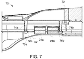
- FIG. 7 is a cross-sectional side view of a luminaire 70 including a tool-less clamping fixture (such as the fixture 60a of FIG. 6A ) including two electronic drivers 24a and 24b affixed to an internal surface of the housing 62.
- a tool-less clamping fixture such as the fixture 60a of FIG. 6A
- two pins 74a and 74b on a fixture-door 72 provide a distributed downward force in areas 76a and 76b when the fixture-door 72 is closed (as shown in FIG. 7 ) to hold the geartray plate 30a at a defined position and permit the flexible strips to provide the pretension force to bias the electronic drivers 24a and 24b toward the internal surface of the housing 62.
- the geartray plate 30a can be used to mount other types of electrical connections and/or connectors, which can be changed and/or replaced without any tools.
- tool-less clamping fixtures as described herein can be used to connect different sizes and configurations of identical or non-identical electronic drivers to luminaires.
- a variety of different sizes and or configurations of flexible strips can be used, and their clamping or affixation locations can be different from that which described above.
- FIGS. 8A-8F are top views of some examples of electronic drivers and their associated flexible strips (wherein no geartray plates are shown).
- FIG. 8A is an exemplary top view 80a of an electronic driver 81a having three flexible strips 82a, 82b and 82c for connection via a geartray plate to a heatsink (not shown).
- Each strip may have one or more concave portions which are bent in a downward direction (for example, see portions 42a and/or 42b of flexible strip 40 in FIG. 4 ) to bias the electronic driver towards, for example, a heat sink when installed in a luminaire.
- a different size electronic driver 81a can be accommodated by appropriately designing the dimensions of the flexible strips 82a, 82b and 82c and the geartray plate.
- FIG. 8B is an exemplary top view of three electronic drivers 81b, 82b and 83b, which can be identical, in which four flexible strips 84a, 84b, 84c and 84d are used for connecting them via a geartray plate to a heatsink (not shown).
- Each strip may have one or more of portions that are bent in a downward direction, and having a wavy or concave shape (like portions 42a or 42b in FIG. 4 ).
- Each of the flexible strips 84b and 84c has an adequate width to cover a gap between two adjacent electronic drivers (along their long-side boundaries), that is between electronic drivers 81b and 82b, and between electronic drivers 82b and 83b, respectively.
- each of two flexible strips 84a and 84d covers one electronic driver 81b or 83b, respectively, around an outside long boundary.
- FIG. 8C is an exemplary top view of two electronic drivers 81c and 82c having different dimensions, and which can be connected via a geartray plate to a heatsink (not shown) with corresponding flexible strips 85a, 85b and 85c, and 85d and 85e, respectively.
- the electronic drivers 81c and 82c have different lengths, but also can have other different dimensions such as height and/or width.
- the electronic driver 81c is fixed/covered by three flexible strips 85a, 85b and 85c, wherein each strip may one or more concave portions to bias the electronic drivers in a downward direction towards a heat sink (not shown) when assembled.
- the electronic driver 82c is associated with two flexible strips 85d and 85e, wherein each strip may have one or more concave portions that bias the electronic driver in a downward direction towards a heat sink when installed in a luminaire.
- a first group of flexible strips 85a, 85b and 85c is associated with the electronic driver 81c
- a second group of flexible strips 85d and 85e is associated with the second electronic driver 82c, wherein the flexible strips may be identical in size and shape or may be different in size and shape, depending on the respective corresponding dimensions of the electronic drivers 81c and 82c.
- FIG. 8D is an exemplary top view of two electronic drivers 81d and 82d, which may or may not be identical, and which can be connected via corresponding flexible strips 86a and 86b, and 86c and 86d, via a geartray plate to a heatsink (not shown).
- Electronic drivers 81d and 82d are placed in a "T" configuration, so that the geartray plate (not shown) may also have a "T" shape and may include two openings (instead of just one generally rectangular opening) .
- Each of the electronic drivers is fixed/covered with two flexible strips (placed on the top of each of the electronic drivers).
- the flexible strips have one or more concave portions to bias the heat sinks in a downward direction towards a heat sink when installed in a luminaire (not shown).
- the two groups of flexible strips 86a and 86b, and 86c and 86d may or may not be identical, and have dimensions which accommodate the dimensions of the electronic drivers 81d and 82d.
- FIG. 8E is an exemplary top view of two electronic drivers 81e and 82e that are associated with corresponding flexible strips 87a and 87b in one direction, and with a flexible strip 88 in another direction (here, perpendicular to the other two strips).
- the construction of the flexible strips 87a, 87b and 88 are varied.
- each strip may include two concave portions to bias the electronic drivers in a downward direction towards a heat sink when installed in a luminaire (not shown).
- the flexible strips 87a and 87b may have two concave portions while the flexible strip 88 has on only one concave portion, and other variations are possible.
- FIG. 8F is an exemplary top view of two electronic drivers 81f and 82f, having different lengths and placed parallel to each other and their associated flexible strips 89a, 89b and 89c, respectively.
- the flexible strips 89a, 89b may include at least two concave portions configured to bias each of electronic drivers 81f and 82f in a downward direction towards a heat sink when installed in a luminaire.
- the flexible strip 89c may have only one concave portion which can provide a further biasing force to the longer electronic driver 81f to provide additional support/pretension.
Landscapes
- Engineering & Computer Science (AREA)
- General Engineering & Computer Science (AREA)
- Power Engineering (AREA)
- Arrangements Of Lighting Devices For Vehicle Interiors, Mounting And Supporting Thereof, Circuits Therefore (AREA)
Applications Claiming Priority (1)
| Application Number | Priority Date | Filing Date | Title |
|---|---|---|---|
| US201615282273A | 2016-09-30 | 2016-09-30 |
Publications (1)
| Publication Number | Publication Date |
|---|---|
| EP3301346A1 true EP3301346A1 (fr) | 2018-04-04 |
Family
ID=60019701
Family Applications (1)
| Application Number | Title | Priority Date | Filing Date |
|---|---|---|---|
| EP17193986.1A Withdrawn EP3301346A1 (fr) | 2016-09-30 | 2017-09-29 | Système de serrage d'alimentationes électroniques d'un luminaire |
Country Status (1)
| Country | Link |
|---|---|
| EP (1) | EP3301346A1 (fr) |
Citations (4)
| Publication number | Priority date | Publication date | Assignee | Title |
|---|---|---|---|---|
| GB1301700A (fr) * | 1970-08-27 | 1973-01-04 | ||
| EP0148334A2 (fr) * | 1983-12-23 | 1985-07-17 | Siemens Aktiengesellschaft | Dispositif pour la fixation d'accessoires sur la paroi d'une armature lumineuse |
| US20060227536A1 (en) * | 2005-03-30 | 2006-10-12 | Haugaard Eric J | Component tray for electrical fixture housing |
| US20070030682A1 (en) * | 2005-08-03 | 2007-02-08 | Ruud Lighting, Inc. | Industrial light fixture with spring-spacer apparatus |
-
2017
- 2017-09-29 EP EP17193986.1A patent/EP3301346A1/fr not_active Withdrawn
Patent Citations (4)
| Publication number | Priority date | Publication date | Assignee | Title |
|---|---|---|---|---|
| GB1301700A (fr) * | 1970-08-27 | 1973-01-04 | ||
| EP0148334A2 (fr) * | 1983-12-23 | 1985-07-17 | Siemens Aktiengesellschaft | Dispositif pour la fixation d'accessoires sur la paroi d'une armature lumineuse |
| US20060227536A1 (en) * | 2005-03-30 | 2006-10-12 | Haugaard Eric J | Component tray for electrical fixture housing |
| US20070030682A1 (en) * | 2005-08-03 | 2007-02-08 | Ruud Lighting, Inc. | Industrial light fixture with spring-spacer apparatus |
Similar Documents
| Publication | Publication Date | Title |
|---|---|---|
| US12203631B2 (en) | Round metal housing for a lighting system | |
| EP2966346B1 (fr) | Améliorations dans ou relatives à des réseaux de lentilles | |
| KR101193336B1 (ko) | 설치 보조 부재 및 조명 장치 | |
| US5260678A (en) | Fluorescent-lamp leadless ballast with improved connector | |
| US5566749A (en) | Stamped and formed heat sink | |
| CA2634333C (fr) | Enceintes pour cartes de circuits a diodes electroluminescentes | |
| CN103596803B (zh) | 用于保持led光源的装置 | |
| US7234832B2 (en) | Adjustable lighting fixture | |
| US10584864B2 (en) | Downlight lighting assembly | |
| CN101116384A (zh) | 印刷电路板固定装置 | |
| US9453620B2 (en) | Strip fixture retrofit systems and methods | |
| US12264807B2 (en) | Mounting accessories for luminaires | |
| US10253960B2 (en) | Retainer apparatus for luminaire assembly | |
| CN104094051A (zh) | 用于将led光源固定至散热器表面上的装置 | |
| US20120222835A1 (en) | Heat dissipating device | |
| US7950446B2 (en) | Heat dissipation device with clip for mounting a fan to a heat sink thereof | |
| US20060162920A1 (en) | Heat sink | |
| JP2016519405A (ja) | 全方向性ledランプ | |
| CN101540488A (zh) | 配线装置以及其安装框 | |
| CN106051655B (zh) | 一种高棚灯及其灯具组件 | |
| US12247722B2 (en) | Mounting bracket | |
| US6305829B1 (en) | Heat conducting multi position reflector neck assembly | |
| CN102454883A (zh) | 发光二极管灯具 | |
| JP6799559B2 (ja) | 照明装置用バネ及び照明装置 | |
| CN220783598U (zh) | 用于灯具散热模块的夹具 |
Legal Events
| Date | Code | Title | Description |
|---|---|---|---|
| PUAI | Public reference made under article 153(3) epc to a published international application that has entered the european phase |
Free format text: ORIGINAL CODE: 0009012 |
|
| STAA | Information on the status of an ep patent application or granted ep patent |
Free format text: STATUS: THE APPLICATION HAS BEEN PUBLISHED |
|
| AK | Designated contracting states |
Kind code of ref document: A1 Designated state(s): AL AT BE BG CH CY CZ DE DK EE ES FI FR GB GR HR HU IE IS IT LI LT LU LV MC MK MT NL NO PL PT RO RS SE SI SK SM TR |
|
| AX | Request for extension of the european patent |
Extension state: BA ME |
|
| STAA | Information on the status of an ep patent application or granted ep patent |
Free format text: STATUS: REQUEST FOR EXAMINATION WAS MADE |
|
| 17P | Request for examination filed |
Effective date: 20181004 |
|
| RBV | Designated contracting states (corrected) |
Designated state(s): AL AT BE BG CH CY CZ DE DK EE ES FI FR GB GR HR HU IE IS IT LI LT LU LV MC MK MT NL NO PL PT RO RS SE SI SK SM TR |
|
| RIC1 | Information provided on ipc code assigned before grant |
Ipc: F21V 23/02 20060101ALI20181018BHEP Ipc: F21S 8/08 20060101AFI20181018BHEP Ipc: F21V 29/70 20150101ALI20181018BHEP Ipc: F21V 17/16 20060101ALI20181018BHEP Ipc: F21W 131/103 20060101ALN20181018BHEP |
|
| GRAP | Despatch of communication of intention to grant a patent |
Free format text: ORIGINAL CODE: EPIDOSNIGR1 |
|
| STAA | Information on the status of an ep patent application or granted ep patent |
Free format text: STATUS: GRANT OF PATENT IS INTENDED |
|
| RIC1 | Information provided on ipc code assigned before grant |
Ipc: F21S 8/08 20060101AFI20181022BHEP Ipc: F21V 17/16 20060101ALI20181022BHEP Ipc: F21W 131/103 20060101ALN20181022BHEP Ipc: F21V 29/70 20150101ALI20181022BHEP Ipc: F21V 23/02 20060101ALI20181022BHEP |
|
| INTG | Intention to grant announced |
Effective date: 20181128 |
|
| STAA | Information on the status of an ep patent application or granted ep patent |
Free format text: STATUS: THE APPLICATION IS DEEMED TO BE WITHDRAWN |
|
| 18D | Application deemed to be withdrawn |
Effective date: 20190409 |