EP0148334A2 - Dispositif pour la fixation d'accessoires sur la paroi d'une armature lumineuse - Google Patents
Dispositif pour la fixation d'accessoires sur la paroi d'une armature lumineuse Download PDFInfo
- Publication number
- EP0148334A2 EP0148334A2 EP84112316A EP84112316A EP0148334A2 EP 0148334 A2 EP0148334 A2 EP 0148334A2 EP 84112316 A EP84112316 A EP 84112316A EP 84112316 A EP84112316 A EP 84112316A EP 0148334 A2 EP0148334 A2 EP 0148334A2
- Authority
- EP
- European Patent Office
- Prior art keywords
- wall
- edge
- accessory holder
- lamp wall
- leg
- Prior art date
- Legal status (The legal status is an assumption and is not a legal conclusion. Google has not performed a legal analysis and makes no representation as to the accuracy of the status listed.)
- Granted
Links
- 210000000078 claw Anatomy 0.000 claims description 16
- 229910000639 Spring steel Inorganic materials 0.000 claims description 6
- 230000001154 acute effect Effects 0.000 claims description 2
- 239000004020 conductor Substances 0.000 description 3
- 239000002184 metal Substances 0.000 description 3
- 241000158147 Sator Species 0.000 description 1
- 239000011324 bead Substances 0.000 description 1
- 239000003990 capacitor Substances 0.000 description 1
- 239000004922 lacquer Substances 0.000 description 1
- 230000001681 protective effect Effects 0.000 description 1
- 239000007858 starting material Substances 0.000 description 1
- 230000007704 transition Effects 0.000 description 1
Images

Classifications
-
- F—MECHANICAL ENGINEERING; LIGHTING; HEATING; WEAPONS; BLASTING
- F21—LIGHTING
- F21V—FUNCTIONAL FEATURES OR DETAILS OF LIGHTING DEVICES OR SYSTEMS THEREOF; STRUCTURAL COMBINATIONS OF LIGHTING DEVICES WITH OTHER ARTICLES, NOT OTHERWISE PROVIDED FOR
- F21V17/00—Fastening of component parts of lighting devices, e.g. shades, globes, refractors, reflectors, filters, screens, grids or protective cages
- F21V17/10—Fastening of component parts of lighting devices, e.g. shades, globes, refractors, reflectors, filters, screens, grids or protective cages characterised by specific fastening means or way of fastening
- F21V17/16—Fastening of component parts of lighting devices, e.g. shades, globes, refractors, reflectors, filters, screens, grids or protective cages characterised by specific fastening means or way of fastening by deformation of parts; Snap action mounting
- F21V17/164—Fastening of component parts of lighting devices, e.g. shades, globes, refractors, reflectors, filters, screens, grids or protective cages characterised by specific fastening means or way of fastening by deformation of parts; Snap action mounting the parts being subjected to bending, e.g. snap joints
-
- F—MECHANICAL ENGINEERING; LIGHTING; HEATING; WEAPONS; BLASTING
- F21—LIGHTING
- F21V—FUNCTIONAL FEATURES OR DETAILS OF LIGHTING DEVICES OR SYSTEMS THEREOF; STRUCTURAL COMBINATIONS OF LIGHTING DEVICES WITH OTHER ARTICLES, NOT OTHERWISE PROVIDED FOR
- F21V17/00—Fastening of component parts of lighting devices, e.g. shades, globes, refractors, reflectors, filters, screens, grids or protective cages
- F21V17/10—Fastening of component parts of lighting devices, e.g. shades, globes, refractors, reflectors, filters, screens, grids or protective cages characterised by specific fastening means or way of fastening
- F21V17/107—Fastening of component parts of lighting devices, e.g. shades, globes, refractors, reflectors, filters, screens, grids or protective cages characterised by specific fastening means or way of fastening using hinge joints
-
- F—MECHANICAL ENGINEERING; LIGHTING; HEATING; WEAPONS; BLASTING
- F21—LIGHTING
- F21V—FUNCTIONAL FEATURES OR DETAILS OF LIGHTING DEVICES OR SYSTEMS THEREOF; STRUCTURAL COMBINATIONS OF LIGHTING DEVICES WITH OTHER ARTICLES, NOT OTHERWISE PROVIDED FOR
- F21V23/00—Arrangement of electric circuit elements in or on lighting devices
- F21V23/02—Arrangement of electric circuit elements in or on lighting devices the elements being transformers, impedances or power supply units, e.g. a transformer with a rectifier
-
- F—MECHANICAL ENGINEERING; LIGHTING; HEATING; WEAPONS; BLASTING
- F21—LIGHTING
- F21V—FUNCTIONAL FEATURES OR DETAILS OF LIGHTING DEVICES OR SYSTEMS THEREOF; STRUCTURAL COMBINATIONS OF LIGHTING DEVICES WITH OTHER ARTICLES, NOT OTHERWISE PROVIDED FOR
- F21V23/00—Arrangement of electric circuit elements in or on lighting devices
Definitions
- the invention relates to an arrangement for holding accessories on a lamp wall according to the preamble of claim 1 or 6.
- the main part of such a luminaire wall which for example can form a rectangular luminaire frame, delimits an assembly space on three sides in which accessories, for example ballasts, compensation capacitors, starters etc. can be accommodated.
- accessories for example ballasts, compensation capacitors, starters etc.
- a reliable ground connection and a possibility of connecting an earth conductor must also be provided.
- the wiring of the luminaire itself and, if necessary, through-wiring that is continuous from luminaire to luminaire must be accommodated and fastened.
- the wiring is therefore also counted as an accessory.
- the invention has for its object to provide an accessory holder that can be easily and reliably installed at any point on a lamp wall according to the preamble of claim 1.
- the end opposite the foot of the accessory holder itself is designed as a spring, which hooks in its desired position with a click seat on the edge of the lamp wall.
- the accessory holder is clamped in the lamp wall with the aid of a spring arm, which is only tensioned by means of a screw connection.
- Both embodiments therefore have in common that the accessory holder can be resiliently clamped at any point on the luminaire wall, that is to say no screws for fastening the accessory holder to the luminaire wall and therefore no holes in the latter are required.
- the accessory holder is to be used to fix heavy accessories, it is advisable to use spring steel. It is also possible to arrange claws on the accessory holder, which provide an electrical connection between the accessory and the accessory holder and, if applicable, between the accessory holder and the luminaire wall.
- the accessory holder can thus also be used to establish a connection between an earth conductor and the lamp wall.
- a sheet metal strip in the form of a flat plug can be bent out of a central part of the accessory holder, onto which a suitable cable lug of an earth conductor can be plugged.
- the accessory holder is only intended to fix the wiring, it is preferably made of plastic.
- FIG. 1 shows in cross section a luminaire wall 1 with a main part 10, which is delimited by a main wall 101 and two transverse walls 102 running approximately perpendicular to it.
- This main part 10 is adjoined at the top and bottom by two identical edge parts 11, each of which is formed by a mounting leg 112, a base 113 and an edge wall 114, which surround a channel 110.
- Each edge part 11 is connected via its edge wall 114 to the transverse wall 102 of the main part 10 such that the openings of the grooves 110 of the two edge parts 11 are directed towards one another.
- a luminaire wall with such a profile has high rigidity and encloses a relatively large mounting space 100 between the main wall 101 and the plane delimited by the mounting leg 112; a ballast, a compensation condenser, for example sator or other accessories.
- a ballast for example sator or other accessories.
- these are lines or cables, they are preferably guided within the channels 110 of the edge parts 11 and secured therein by the accessory holder 2.1 shown in FIG. 1.
- Such an accessory holder 2.1 specializing in this function is a plastic molded part of approximately 1 cm in width (in the direction perpendicular to the plane of the drawing) and has a central part 20.1 which extends approximately in the extension of the mounting leg 112, that is to say leaves the mounting space 100 free.
- a C-shaped foot 21.1 with a semicircular end piece 211.1 and a connecting piece 212.1 is formed on one end of the middle part 20.1.
- a V-shaped spring 22.1 is formed with a spring leg 221.1 and a connecting leg 222.1; at the end of the spring leg 221.1 there is a detent seat 223.1 with a locking stop 2231.1 and a travel stop 2232.1 running at right angles thereto, which limits the travel of the spring 22.1.
- the accessory holder 2.1 is supported on the inside with the locking stop 2231.1 and resiliently on the edge 1120 of the mounting leg 112 with the travel stop 2232.1.
- the spring leg 221.1 also bears against the transition between the walls I02 and 114, as a result of which the position shown in FIG. 1 is additionally secured.
- the accessory holder 2.1 is thus resiliently clamped between the bottom 113 of the lower edge part 11 of the lamp wall 1 and the edge 1120 of the upper edge part 11.
- the distance between the end piece 211.1 of the foot of the accessory holder and the detent seat 223.1 is therefore greater in the relaxed state - shown in broken lines in FIG. 1 - than the distance between the bottom 113 of the one edge part 11 and the edge 1120 of the other edge part 11 of the lamp wall 1.
- the opening 210.1 of the C-shaped foot 21.1 projects beyond the height of the mounting leg 112 at least to such an extent that the accessory holder can be used in the oblique position shown in dashed lines in FIG.
- the outer diameter of the end piece 211.1 of the foot 21.1 is only slightly larger than the inside width of the groove 110 of the edge 11 of the lamp wall 1, so that a practically play-free storage of the accessory holder and at the same time a rotation in the lamp wall is possible.
- the accessory holder 2.1 closes the groove 110 of the upper edge part 11 of the lamp wall 1 with its spring leg 221.1 and secures the lines accommodated therein against falling out. By pressing down the spring leg 221.1, individual lines can be easily inserted or removed.
- Cables in particular for through-wiring, can also be accommodated in the C-shaped foot 21.1. They are secured against falling out by a resilient locking leg 202.1, which is directed from the middle part 20.1 against the end piece 211.1 and which blocks the part of the opening 210.1 lying above the mounting leg 112.
- FIGS. 2 to 4 relate to an accessory holder 2 made of spring steel, which is suitable for holding heavier accessories and at the same time for earthing them, and which accordingly has a greater extent in the direction perpendicular to the plane of the drawing (FIG. 3).
- the detent seats 223 are designed in particular: for this purpose, the spring leg 221 has at its end two end pieces 224, which are angled against the foot 21 of the accessory holder 2, approximately vertically stand on the spring leg 221 and serve as a locking stop 2231. Each of these end pieces 224 has an edge tab 225 at both ends, which in turn is perpendicular to the end piece 224 (FIG.
- edge tabs 225 point away from the central part 20.
- Each of these edge tabs 225 now has a cutting edge 2251 which is at an angle to the plane of the end piece 224 and serves as a travel stop 2232 (FIG. 2).
- the accessory holder 2 is inserted into the lamp wall 1 in the same way as that according to FIG. 1: the spring leg 221 is pressed down again by the edge 1120 of the mounting leg 112 until the edge 1120 snaps into the detent seat 223 of the accessory holder 2.
- the accessory holder 2 is supported with the locking stop 2231 against the inside of the mounting leg 112;
- the sharp cutting edges 2251 of the four edge tabs 225 (FIG. 3) notch into the bare edge 1120 and thus ensure a reliable electrical connection and a limitation of the spring travel.
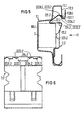
- the end piece 224.2 is angled downwards relative to the spring leg 221.2 and additionally has a handle 2234.2.
- At the end of the spring leg there are two locking stops 2231.2 and two on each side of the end piece Claws 2233.2 are provided for each stop.
- the claws 2233.2 penetrate any protective lacquer that may be present and impress themselves in the bare metal of the luminaire wall 1.1. Since the tips of the claws can be deformed somewhat, these claws are preferably slightly longer than the locking stops 2231.2 which transmit the pressure forces, so that perfect electrical contact is ensured under all conditions.
- the accessories can be attached directly to the middle part 20.2 of the accessory holder 2.2, e.g. attached to a bent rag by screws.
- the accessories for example a ballast 3
- claws 201.2 in the middle part 20.2 can ensure a reliable electrical connection between the accessories and the accessory holder.
- the middle part 20.2 can have a curvature directed against the lamp wall 1.1 or can be provided with stiffening beads.
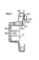
- the accessory holder 2.3 is resiliently clamped on the lamp wall in such a way that the middle part 20.3 and claws 201.3 rest on the inside of the main wall 101.1 of the lamp wall 1.1.
- a foot 21.3 with the features already described is arranged at one end of the middle part 20.3.
- the accessory holder 2.3 has a connecting leg 222.3 which is directed upwards against the channel 110.1 and in which two screw connections 226.3 are arranged one behind the other at a distance.
- a clamping plate 23.3 is fastened to the connecting leg 222.3 and engages with a spring arm 231.3 in the channel 110.1.
- This spring arm - the relaxed position of which is shown in dashed lines in FIG. 7 - presses the middle part 20.3 against the main wall 101.1 when the screw connection is tightened - shown in the figure.
- the free end of the spring arm has additional claws.
- the clamping plate 23.3 has a slot 226.3 each screw, which extends transversely to the longitudinal axis of the lamp wall as far into the spring arm 231.3 that the clamping plate can be pulled down so far after loosening the screw connection 226.3 that the accessory holder 2.3 around its foot 21.3 under the opposite edge 1120.1 is pivotable outwards.
Landscapes
- Engineering & Computer Science (AREA)
- General Engineering & Computer Science (AREA)
- Power Engineering (AREA)
- Fastening Of Light Sources Or Lamp Holders (AREA)
- Non-Portable Lighting Devices Or Systems Thereof (AREA)
- Lighters Containing Fuel (AREA)
- Golf Clubs (AREA)
- Sheet Holders (AREA)
- Vessels And Coating Films For Discharge Lamps (AREA)
- Lighting Device Outwards From Vehicle And Optical Signal (AREA)
- Arrangement Of Elements, Cooling, Sealing, Or The Like Of Lighting Devices (AREA)
Priority Applications (1)
| Application Number | Priority Date | Filing Date | Title |
|---|---|---|---|
| AT84112316T ATE49286T1 (de) | 1983-12-23 | 1984-10-12 | Anordnung zur halterung von zubehoer an einer leuchtenwand. |
Applications Claiming Priority (2)
| Application Number | Priority Date | Filing Date | Title |
|---|---|---|---|
| DE3346826 | 1983-12-23 | ||
| DE19833346826 DE3346826A1 (de) | 1983-12-23 | 1983-12-23 | Zubehoerhalter fuer eine leuchtenwand |
Publications (3)
| Publication Number | Publication Date |
|---|---|
| EP0148334A2 true EP0148334A2 (fr) | 1985-07-17 |
| EP0148334A3 EP0148334A3 (en) | 1987-07-22 |
| EP0148334B1 EP0148334B1 (fr) | 1990-01-03 |
Family
ID=6217960
Family Applications (1)
| Application Number | Title | Priority Date | Filing Date |
|---|---|---|---|
| EP84112316A Expired - Lifetime EP0148334B1 (fr) | 1983-12-23 | 1984-10-12 | Dispositif pour la fixation d'accessoires sur la paroi d'une armature lumineuse |
Country Status (6)
| Country | Link |
|---|---|
| EP (1) | EP0148334B1 (fr) |
| AT (1) | ATE49286T1 (fr) |
| DE (2) | DE3346826A1 (fr) |
| GR (1) | GR82581B (fr) |
| NO (1) | NO162168C (fr) |
| ZA (1) | ZA848223B (fr) |
Cited By (6)
| Publication number | Priority date | Publication date | Assignee | Title |
|---|---|---|---|---|
| EP0377109A1 (fr) * | 1988-12-03 | 1990-07-11 | Licentia Patent-Verwaltungs-GmbH | Boîtier pour appareil d'éclairage des rues |
| GB2300471A (en) * | 1995-04-03 | 1996-11-06 | Louvre Company Limited The | A reflector unit |
| EP1052452A1 (fr) * | 1999-05-11 | 2000-11-15 | Koninklijke Philips Electronics N.V. | Luminaire de forme allongée |
| AT13774U1 (de) * | 2013-04-30 | 2014-08-15 | Zumtobel Lighting Gmbh | Leuchte |
| EP2876366A1 (fr) * | 2013-11-25 | 2015-05-27 | Bega Gantenbrink-Leuchten KG | Lampe avec élément de serrage |
| EP3301346A1 (fr) * | 2016-09-30 | 2018-04-04 | GE Lighting Solutions, LLC | Système de serrage d'alimentationes électroniques d'un luminaire |
Families Citing this family (2)
| Publication number | Priority date | Publication date | Assignee | Title |
|---|---|---|---|---|
| US4947301A (en) * | 1989-05-04 | 1990-08-07 | Charles Steele | Neon tube electrode housing |
| CN112032621B (zh) * | 2020-08-04 | 2022-01-14 | 厦门普为光电科技有限公司 | 轨道灯 |
Family Cites Families (6)
| Publication number | Priority date | Publication date | Assignee | Title |
|---|---|---|---|---|
| BE506075A (fr) * | ||||
| DE1751296U (de) * | 1957-02-18 | 1957-08-29 | Licentia Gmbh | Beruehrungsschutz fuer vorschaltgeraete und anschlussteile in leuchten mit roehrenfoermigen lampen. |
| US3101922A (en) * | 1962-03-07 | 1963-08-27 | Gen Motors Corp | Snap fastener |
| DE1489520A1 (de) * | 1965-07-10 | 1969-04-03 | Siemens Ag | Leuchte fuer Leuchtstofflampen mit festgeklemmter Drosselspule |
| US4472917A (en) * | 1981-09-24 | 1984-09-25 | Henry Lindsay Limited | Fixing device for mounting a plate on the flange of a beam |
| DE8220827U1 (de) * | 1982-07-21 | 1982-11-25 | Siemens AG, 1000 Berlin und 8000 München | Halterung eines zubehoertraegers an einem leuchtentraeger |
-
1983
- 1983-12-23 DE DE19833346826 patent/DE3346826A1/de not_active Withdrawn
-
1984
- 1984-10-12 DE DE8484112316T patent/DE3480946D1/de not_active Expired - Lifetime
- 1984-10-12 EP EP84112316A patent/EP0148334B1/fr not_active Expired - Lifetime
- 1984-10-12 AT AT84112316T patent/ATE49286T1/de active
- 1984-10-19 NO NO844186A patent/NO162168C/no unknown
- 1984-10-22 ZA ZA848223A patent/ZA848223B/xx unknown
- 1984-12-21 GR GR82581A patent/GR82581B/el unknown
Cited By (7)
| Publication number | Priority date | Publication date | Assignee | Title |
|---|---|---|---|---|
| EP0377109A1 (fr) * | 1988-12-03 | 1990-07-11 | Licentia Patent-Verwaltungs-GmbH | Boîtier pour appareil d'éclairage des rues |
| GB2300471A (en) * | 1995-04-03 | 1996-11-06 | Louvre Company Limited The | A reflector unit |
| EP1052452A1 (fr) * | 1999-05-11 | 2000-11-15 | Koninklijke Philips Electronics N.V. | Luminaire de forme allongée |
| AT13774U1 (de) * | 2013-04-30 | 2014-08-15 | Zumtobel Lighting Gmbh | Leuchte |
| EP2876366A1 (fr) * | 2013-11-25 | 2015-05-27 | Bega Gantenbrink-Leuchten KG | Lampe avec élément de serrage |
| US9739456B2 (en) | 2013-11-25 | 2017-08-22 | Bega Gantenbrink-Leuchten Kg | Luminaire having a clamping member |
| EP3301346A1 (fr) * | 2016-09-30 | 2018-04-04 | GE Lighting Solutions, LLC | Système de serrage d'alimentationes électroniques d'un luminaire |
Also Published As
| Publication number | Publication date |
|---|---|
| ZA848223B (en) | 1985-07-31 |
| DE3346826A1 (de) | 1985-07-11 |
| NO162168C (no) | 1989-11-15 |
| EP0148334B1 (fr) | 1990-01-03 |
| DE3480946D1 (de) | 1990-02-08 |
| ATE49286T1 (de) | 1990-01-15 |
| NO162168B (no) | 1989-08-07 |
| EP0148334A3 (en) | 1987-07-22 |
| GR82581B (en) | 1985-04-23 |
| NO844186L (no) | 1985-06-24 |
Similar Documents
| Publication | Publication Date | Title |
|---|---|---|
| DE2544893C2 (de) | Elektrisches Verbindungselement für eine Klemmverbindung und eine elektrische Verbindung | |
| DE3788047T2 (de) | Halteclip. | |
| DE3882421T2 (de) | Elektrischer Gerätesockel zum Aufstellen in einem Leitungsführungskanal. | |
| EP3477792A1 (fr) | Connecteur enfichable de prise et contact de mise à la terre de protection correspondant | |
| EP0010251A1 (fr) | Dispositif pour la fixation d'appareils d'installation | |
| DE202017107144U1 (de) | Set aus Steckverbinder und Halteelement sowie Steckverbinder und Halteelement hierzu | |
| EP0148334A2 (fr) | Dispositif pour la fixation d'accessoires sur la paroi d'une armature lumineuse | |
| DE19524381C2 (de) | Installationskanal mit einem zu einer Seite offenen metallischen Kanalprofil | |
| EP0140058B1 (fr) | Support pour appareil d'éclairage encastré | |
| DE69009183T2 (de) | Befestigungsmittel. | |
| DE2852829A1 (de) | Schnellmontagesockel aus kunststoff | |
| DE102018119525A1 (de) | Abgriffsteckverbinder und Schutzerdungskontakt hierzu | |
| EP0621439A1 (fr) | Appareil d'éclairage consistant en tubes luminescents formant une bande lumineuse | |
| DE3201169C2 (de) | Vorrichtung zum Festklemmen elektrischer Leiter insbesondere von Drähten | |
| DE19949508A1 (de) | Vorrichtung zur Befestigung von Schirmklemmen | |
| DE69600846T2 (de) | Geräteträger für ein teilweise in einer Leitung versenktes Gehäuse, und Verfahren zu seiner Durchführung | |
| DE8500148U1 (de) | Vorrichtung zum Potentialausgleich für Erdleiter von elektrischen Installationen | |
| DE102017113811A1 (de) | Anordnung für einen Verteilerkasten | |
| EP0901186A2 (fr) | Borne de connexion pour des câbles blindés | |
| DE2320982C3 (de) | Mehrleiterstromschiene | |
| DE29502779U1 (de) | Potentialverteilungsvorrichtung für elektrische Anlagen | |
| DE69609686T2 (de) | Elektrische Schaltung aus mindestens einem Band hergestellt, insbesondere für Fahrzeuganzeigelampen, mit mindestens einem Steckelement das durch Biegen hergestellt wurde | |
| DE3220456A1 (de) | Lampentraeger | |
| DE69504403T2 (de) | Anschlussleistenträger in Schaltschrank oder dergleichen | |
| DE3037450C1 (de) | Steckdose |
Legal Events
| Date | Code | Title | Description |
|---|---|---|---|
| PUAI | Public reference made under article 153(3) epc to a published international application that has entered the european phase |
Free format text: ORIGINAL CODE: 0009012 |
|
| AK | Designated contracting states |
Designated state(s): AT CH DE IT LI SE |
|
| PUAL | Search report despatched |
Free format text: ORIGINAL CODE: 0009013 |
|
| AK | Designated contracting states |
Kind code of ref document: A3 Designated state(s): AT CH DE IT LI SE |
|
| 17P | Request for examination filed |
Effective date: 19871218 |
|
| 17Q | First examination report despatched |
Effective date: 19881122 |
|
| GRAA | (expected) grant |
Free format text: ORIGINAL CODE: 0009210 |
|
| AK | Designated contracting states |
Kind code of ref document: B1 Designated state(s): AT CH DE IT LI SE |
|
| REF | Corresponds to: |
Ref document number: 49286 Country of ref document: AT Date of ref document: 19900115 Kind code of ref document: T |
|
| REF | Corresponds to: |
Ref document number: 3480946 Country of ref document: DE Date of ref document: 19900208 |
|
| ITF | It: translation for a ep patent filed | ||
| PLBE | No opposition filed within time limit |
Free format text: ORIGINAL CODE: 0009261 |
|
| STAA | Information on the status of an ep patent application or granted ep patent |
Free format text: STATUS: NO OPPOSITION FILED WITHIN TIME LIMIT |
|
| 26N | No opposition filed | ||
| ITTA | It: last paid annual fee | ||
| PGFP | Annual fee paid to national office [announced via postgrant information from national office to epo] |
Ref country code: CH Payment date: 19950118 Year of fee payment: 11 |
|
| EAL | Se: european patent in force in sweden |
Ref document number: 84112316.9 |
|
| PGFP | Annual fee paid to national office [announced via postgrant information from national office to epo] |
Ref country code: SE Payment date: 19951019 Year of fee payment: 12 |
|
| PG25 | Lapsed in a contracting state [announced via postgrant information from national office to epo] |
Ref country code: LI Effective date: 19951031 Ref country code: CH Effective date: 19951031 |
|
| REG | Reference to a national code |
Ref country code: CH Ref legal event code: PL |
|
| PG25 | Lapsed in a contracting state [announced via postgrant information from national office to epo] |
Ref country code: SE Effective date: 19961013 |
|
| EUG | Se: european patent has lapsed |
Ref document number: 84112316.9 |
|
| PGFP | Annual fee paid to national office [announced via postgrant information from national office to epo] |
Ref country code: AT Payment date: 19970926 Year of fee payment: 14 |
|
| PGFP | Annual fee paid to national office [announced via postgrant information from national office to epo] |
Ref country code: DE Payment date: 19971218 Year of fee payment: 14 |
|
| PG25 | Lapsed in a contracting state [announced via postgrant information from national office to epo] |
Ref country code: AT Free format text: LAPSE BECAUSE OF NON-PAYMENT OF DUE FEES Effective date: 19981012 |
|
| PG25 | Lapsed in a contracting state [announced via postgrant information from national office to epo] |
Ref country code: DE Free format text: LAPSE BECAUSE OF NON-PAYMENT OF DUE FEES Effective date: 19990803 |