EP3301378A1 - Tuyau de transfert de chaleur et chaudière dotée d'un tel tuyau de transfert de chaleur - Google Patents
Tuyau de transfert de chaleur et chaudière dotée d'un tel tuyau de transfert de chaleur Download PDFInfo
- Publication number
- EP3301378A1 EP3301378A1 EP17198940.3A EP17198940A EP3301378A1 EP 3301378 A1 EP3301378 A1 EP 3301378A1 EP 17198940 A EP17198940 A EP 17198940A EP 3301378 A1 EP3301378 A1 EP 3301378A1
- Authority
- EP
- European Patent Office
- Prior art keywords
- outer tube
- heat exchanger
- tube
- cross
- indentations
- Prior art date
- Legal status (The legal status is an assumption and is not a legal conclusion. Google has not performed a legal analysis and makes no representation as to the accuracy of the status listed.)
- Granted
Links
Images


Classifications
-
- F—MECHANICAL ENGINEERING; LIGHTING; HEATING; WEAPONS; BLASTING
- F22—STEAM GENERATION
- F22B—METHODS OF STEAM GENERATION; STEAM BOILERS
- F22B9/00—Steam boilers of fire-tube type, i.e. the flue gas from a combustion chamber outside the boiler body flowing through tubes built-in in the boiler body
- F22B9/02—Steam boilers of fire-tube type, i.e. the flue gas from a combustion chamber outside the boiler body flowing through tubes built-in in the boiler body the boiler body being disposed upright, e.g. above the combustion chamber
-
- F—MECHANICAL ENGINEERING; LIGHTING; HEATING; WEAPONS; BLASTING
- F24—HEATING; RANGES; VENTILATING
- F24H—FLUID HEATERS, e.g. WATER OR AIR HEATERS, HAVING HEAT-GENERATING MEANS, e.g. HEAT PUMPS, IN GENERAL
- F24H1/00—Water heaters, e.g. boilers, continuous-flow heaters or water-storage heaters
- F24H1/18—Water-storage heaters
- F24H1/20—Water-storage heaters with immersed heating elements, e.g. electric elements or furnace tubes
- F24H1/205—Water-storage heaters with immersed heating elements, e.g. electric elements or furnace tubes with furnace tubes
-
- F—MECHANICAL ENGINEERING; LIGHTING; HEATING; WEAPONS; BLASTING
- F24—HEATING; RANGES; VENTILATING
- F24H—FLUID HEATERS, e.g. WATER OR AIR HEATERS, HAVING HEAT-GENERATING MEANS, e.g. HEAT PUMPS, IN GENERAL
- F24H1/00—Water heaters, e.g. boilers, continuous-flow heaters or water-storage heaters
- F24H1/22—Water heaters other than continuous-flow or water-storage heaters, e.g. water heaters for central heating
- F24H1/24—Water heaters other than continuous-flow or water-storage heaters, e.g. water heaters for central heating with water mantle surrounding the combustion chamber or chambers
- F24H1/26—Water heaters other than continuous-flow or water-storage heaters, e.g. water heaters for central heating with water mantle surrounding the combustion chamber or chambers the water mantle forming an integral body
- F24H1/28—Water heaters other than continuous-flow or water-storage heaters, e.g. water heaters for central heating with water mantle surrounding the combustion chamber or chambers the water mantle forming an integral body including one or more furnace or fire tubes
- F24H1/282—Water heaters other than continuous-flow or water-storage heaters, e.g. water heaters for central heating with water mantle surrounding the combustion chamber or chambers the water mantle forming an integral body including one or more furnace or fire tubes with flue gas passages built-up by coaxial water mantles
-
- F—MECHANICAL ENGINEERING; LIGHTING; HEATING; WEAPONS; BLASTING
- F24—HEATING; RANGES; VENTILATING
- F24H—FLUID HEATERS, e.g. WATER OR AIR HEATERS, HAVING HEAT-GENERATING MEANS, e.g. HEAT PUMPS, IN GENERAL
- F24H1/00—Water heaters, e.g. boilers, continuous-flow heaters or water-storage heaters
-
- F—MECHANICAL ENGINEERING; LIGHTING; HEATING; WEAPONS; BLASTING
- F24—HEATING; RANGES; VENTILATING
- F24H—FLUID HEATERS, e.g. WATER OR AIR HEATERS, HAVING HEAT-GENERATING MEANS, e.g. HEAT PUMPS, IN GENERAL
- F24H1/00—Water heaters, e.g. boilers, continuous-flow heaters or water-storage heaters
- F24H1/22—Water heaters other than continuous-flow or water-storage heaters, e.g. water heaters for central heating
- F24H1/24—Water heaters other than continuous-flow or water-storage heaters, e.g. water heaters for central heating with water mantle surrounding the combustion chamber or chambers
- F24H1/26—Water heaters other than continuous-flow or water-storage heaters, e.g. water heaters for central heating with water mantle surrounding the combustion chamber or chambers the water mantle forming an integral body
- F24H1/28—Water heaters other than continuous-flow or water-storage heaters, e.g. water heaters for central heating with water mantle surrounding the combustion chamber or chambers the water mantle forming an integral body including one or more furnace or fire tubes
-
- F—MECHANICAL ENGINEERING; LIGHTING; HEATING; WEAPONS; BLASTING
- F24—HEATING; RANGES; VENTILATING
- F24H—FLUID HEATERS, e.g. WATER OR AIR HEATERS, HAVING HEAT-GENERATING MEANS, e.g. HEAT PUMPS, IN GENERAL
- F24H8/00—Fluid heaters characterised by means for extracting latent heat from flue gases by means of condensation
-
- F—MECHANICAL ENGINEERING; LIGHTING; HEATING; WEAPONS; BLASTING
- F24—HEATING; RANGES; VENTILATING
- F24H—FLUID HEATERS, e.g. WATER OR AIR HEATERS, HAVING HEAT-GENERATING MEANS, e.g. HEAT PUMPS, IN GENERAL
- F24H9/00—Details
- F24H9/0005—Details for water heaters
- F24H9/001—Guiding means
- F24H9/0026—Guiding means in combustion gas channels
-
- F—MECHANICAL ENGINEERING; LIGHTING; HEATING; WEAPONS; BLASTING
- F24—HEATING; RANGES; VENTILATING
- F24H—FLUID HEATERS, e.g. WATER OR AIR HEATERS, HAVING HEAT-GENERATING MEANS, e.g. HEAT PUMPS, IN GENERAL
- F24H9/00—Details
- F24H9/0005—Details for water heaters
- F24H9/001—Guiding means
- F24H9/0026—Guiding means in combustion gas channels
- F24H9/0031—Guiding means in combustion gas channels with means for changing or adapting the path of the flue gas
-
- F—MECHANICAL ENGINEERING; LIGHTING; HEATING; WEAPONS; BLASTING
- F28—HEAT EXCHANGE IN GENERAL
- F28D—HEAT-EXCHANGE APPARATUS, NOT PROVIDED FOR IN ANOTHER SUBCLASS, IN WHICH THE HEAT-EXCHANGE MEDIA DO NOT COME INTO DIRECT CONTACT
- F28D1/00—Heat-exchange apparatus having stationary conduit assemblies for one heat-exchange medium only, the media being in contact with different sides of the conduit wall, in which the other heat-exchange medium is a large body of fluid, e.g. domestic or motor car radiators
- F28D1/02—Heat-exchange apparatus having stationary conduit assemblies for one heat-exchange medium only, the media being in contact with different sides of the conduit wall, in which the other heat-exchange medium is a large body of fluid, e.g. domestic or motor car radiators with heat-exchange conduits immersed in the body of fluid
- F28D1/0206—Heat exchangers immersed in a large body of liquid
-
- F—MECHANICAL ENGINEERING; LIGHTING; HEATING; WEAPONS; BLASTING
- F28—HEAT EXCHANGE IN GENERAL
- F28D—HEAT-EXCHANGE APPARATUS, NOT PROVIDED FOR IN ANOTHER SUBCLASS, IN WHICH THE HEAT-EXCHANGE MEDIA DO NOT COME INTO DIRECT CONTACT
- F28D7/00—Heat-exchange apparatus having stationary tubular conduit assemblies for both heat-exchange media, the media being in contact with different sides of a conduit wall
- F28D7/10—Heat-exchange apparatus having stationary tubular conduit assemblies for both heat-exchange media, the media being in contact with different sides of a conduit wall the conduits being arranged one within the other, e.g. concentrically
- F28D7/103—Heat-exchange apparatus having stationary tubular conduit assemblies for both heat-exchange media, the media being in contact with different sides of a conduit wall the conduits being arranged one within the other, e.g. concentrically consisting of more than two coaxial conduits or modules of more than two coaxial conduits
-
- F—MECHANICAL ENGINEERING; LIGHTING; HEATING; WEAPONS; BLASTING
- F28—HEAT EXCHANGE IN GENERAL
- F28F—DETAILS OF HEAT-EXCHANGE AND HEAT-TRANSFER APPARATUS, OF GENERAL APPLICATION
- F28F1/00—Tubular elements; Assemblies of tubular elements
- F28F1/006—Tubular elements; Assemblies of tubular elements with variable shape, e.g. with modified tube ends, with different geometrical features
-
- F—MECHANICAL ENGINEERING; LIGHTING; HEATING; WEAPONS; BLASTING
- F28—HEAT EXCHANGE IN GENERAL
- F28F—DETAILS OF HEAT-EXCHANGE AND HEAT-TRANSFER APPARATUS, OF GENERAL APPLICATION
- F28F1/00—Tubular elements; Assemblies of tubular elements
- F28F1/02—Tubular elements of cross-section which is non-circular
- F28F1/025—Tubular elements of cross-section which is non-circular with variable shape, e.g. with modified tube ends, with different geometrical features
-
- F—MECHANICAL ENGINEERING; LIGHTING; HEATING; WEAPONS; BLASTING
- F28—HEAT EXCHANGE IN GENERAL
- F28F—DETAILS OF HEAT-EXCHANGE AND HEAT-TRANSFER APPARATUS, OF GENERAL APPLICATION
- F28F1/00—Tubular elements; Assemblies of tubular elements
- F28F1/02—Tubular elements of cross-section which is non-circular
- F28F1/06—Tubular elements of cross-section which is non-circular crimped or corrugated in cross-section
-
- F—MECHANICAL ENGINEERING; LIGHTING; HEATING; WEAPONS; BLASTING
- F28—HEAT EXCHANGE IN GENERAL
- F28F—DETAILS OF HEAT-EXCHANGE AND HEAT-TRANSFER APPARATUS, OF GENERAL APPLICATION
- F28F1/00—Tubular elements; Assemblies of tubular elements
- F28F1/10—Tubular elements and assemblies thereof with means for increasing heat-transfer area, e.g. with fins, with projections, with recesses
- F28F1/105—Tubular elements and assemblies thereof with means for increasing heat-transfer area, e.g. with fins, with projections, with recesses the means being corrugated elements extending around the tubular elements
-
- F—MECHANICAL ENGINEERING; LIGHTING; HEATING; WEAPONS; BLASTING
- F28—HEAT EXCHANGE IN GENERAL
- F28F—DETAILS OF HEAT-EXCHANGE AND HEAT-TRANSFER APPARATUS, OF GENERAL APPLICATION
- F28F1/00—Tubular elements; Assemblies of tubular elements
- F28F1/10—Tubular elements and assemblies thereof with means for increasing heat-transfer area, e.g. with fins, with projections, with recesses
- F28F1/40—Tubular elements and assemblies thereof with means for increasing heat-transfer area, e.g. with fins, with projections, with recesses the means being only inside the tubular element
-
- F—MECHANICAL ENGINEERING; LIGHTING; HEATING; WEAPONS; BLASTING
- F28—HEAT EXCHANGE IN GENERAL
- F28F—DETAILS OF HEAT-EXCHANGE AND HEAT-TRANSFER APPARATUS, OF GENERAL APPLICATION
- F28F13/00—Arrangements for modifying heat-transfer, e.g. increasing, decreasing
- F28F13/06—Arrangements for modifying heat-transfer, e.g. increasing, decreasing by affecting the pattern of flow of the heat-exchange media
-
- F—MECHANICAL ENGINEERING; LIGHTING; HEATING; WEAPONS; BLASTING
- F28—HEAT EXCHANGE IN GENERAL
- F28F—DETAILS OF HEAT-EXCHANGE AND HEAT-TRANSFER APPARATUS, OF GENERAL APPLICATION
- F28F13/00—Arrangements for modifying heat-transfer, e.g. increasing, decreasing
- F28F13/06—Arrangements for modifying heat-transfer, e.g. increasing, decreasing by affecting the pattern of flow of the heat-exchange media
- F28F13/12—Arrangements for modifying heat-transfer, e.g. increasing, decreasing by affecting the pattern of flow of the heat-exchange media by creating turbulence, e.g. by stirring, by increasing the force of circulation
-
- F—MECHANICAL ENGINEERING; LIGHTING; HEATING; WEAPONS; BLASTING
- F28—HEAT EXCHANGE IN GENERAL
- F28F—DETAILS OF HEAT-EXCHANGE AND HEAT-TRANSFER APPARATUS, OF GENERAL APPLICATION
- F28F21/00—Constructions of heat-exchange apparatus characterised by the selection of particular materials
- F28F21/08—Constructions of heat-exchange apparatus characterised by the selection of particular materials of metal
- F28F21/081—Heat exchange elements made from metals or metal alloys
- F28F21/082—Heat exchange elements made from metals or metal alloys from steel or ferrous alloys
-
- F—MECHANICAL ENGINEERING; LIGHTING; HEATING; WEAPONS; BLASTING
- F28—HEAT EXCHANGE IN GENERAL
- F28F—DETAILS OF HEAT-EXCHANGE AND HEAT-TRANSFER APPARATUS, OF GENERAL APPLICATION
- F28F21/00—Constructions of heat-exchange apparatus characterised by the selection of particular materials
- F28F21/08—Constructions of heat-exchange apparatus characterised by the selection of particular materials of metal
- F28F21/081—Heat exchange elements made from metals or metal alloys
- F28F21/084—Heat exchange elements made from metals or metal alloys from aluminium or aluminium alloys
-
- F—MECHANICAL ENGINEERING; LIGHTING; HEATING; WEAPONS; BLASTING
- F28—HEAT EXCHANGE IN GENERAL
- F28F—DETAILS OF HEAT-EXCHANGE AND HEAT-TRANSFER APPARATUS, OF GENERAL APPLICATION
- F28F2210/00—Heat exchange conduits
- F28F2210/10—Particular layout, e.g. for uniform temperature distribution
-
- F—MECHANICAL ENGINEERING; LIGHTING; HEATING; WEAPONS; BLASTING
- F28—HEAT EXCHANGE IN GENERAL
- F28F—DETAILS OF HEAT-EXCHANGE AND HEAT-TRANSFER APPARATUS, OF GENERAL APPLICATION
- F28F2275/00—Fastening; Joining
- F28F2275/14—Fastening; Joining by using form fitting connection, e.g. with tongue and groove
-
- Y—GENERAL TAGGING OF NEW TECHNOLOGICAL DEVELOPMENTS; GENERAL TAGGING OF CROSS-SECTIONAL TECHNOLOGIES SPANNING OVER SEVERAL SECTIONS OF THE IPC; TECHNICAL SUBJECTS COVERED BY FORMER USPC CROSS-REFERENCE ART COLLECTIONS [XRACs] AND DIGESTS
- Y02—TECHNOLOGIES OR APPLICATIONS FOR MITIGATION OR ADAPTATION AGAINST CLIMATE CHANGE
- Y02B—CLIMATE CHANGE MITIGATION TECHNOLOGIES RELATED TO BUILDINGS, e.g. HOUSING, HOUSE APPLIANCES OR RELATED END-USER APPLICATIONS
- Y02B30/00—Energy efficient heating, ventilation or air conditioning [HVAC]
Definitions
- the invention is directed to a heat exchanger tube of a boiler, in particular a condensing boiler, comprising an outer tube which can be flowed through by exhaust gases of the boiler and the outside of the heating water may be surrounded, and inserted into the outer tube profile insert, which increases the inner surface of the Having outer tube in the longitudinal direction extending ribs and is in heat-conducting contact with the outer tube, wherein a first longitudinal portion of the outer tube is cylindrical smooth-walled and a second longitudinal portion of the outer tube has at least one narrowing the flow area cross-sectional constriction element, wherein the profile insert exclusively over the first longitudinal portion of Outer tube extends, wherein the at least one cross-sectional constriction element comprises at least two first recesses, which in the wall of the second longitudinal section of the outer tube out e are formed, and wherein the two first recesses are arranged diametrically opposite and are formed with respect to a first pipe plane mirror-symmetrical.
- the invention is directed to a boiler, in particular a condensing boiler, for heating heating water of a heating circuit, comprising a housing which defines a Schumacherraum and which has a Schuwasserraum the upstream combustion chamber.
- Such a boiler of the type described can be operated as a condensing boiler with a gas firing or liquid firing (fuel oil, kerosene or the like).
- a gas firing or liquid firing fuel oil, kerosene or the like.
- the combustion gases are cooled until the condensation of the exhaust gas moisture to exploit the heat of condensation.
- the prerequisite is that the boiler or condensing boiler is operated at a temperature of the heating water, which is lower than the dew point temperature of the combustion gases at the end of the combustion gas path through the boiler.
- Efforts are made to cool the combustion gases from the high inlet temperature to the lowest heating water temperature prevailing between the dew point temperature and the heating water return of the boiler on the shortest possible path of the combustion gases through the water-cooled heat exchanger tubes of the boiler.
- heat transfer tubes wherein a heat exchanger tube of the type described, for example, from the EP 0 752 088 A1 and the EP 2 781 873 A1 is known.
- the invention has for its object to provide a solution that provides a structurally simple manner and cost, a heat exchanger tube and a boiler, which allow an even greater heat transfer performance of the combustion gases to the heating water in the boiler.
- the object is achieved in that the cross-sectional constriction element in addition to the at least two first recesses at least two second recesses formed by the wall of the second longitudinal section of the outer tube, wherein the two second indentations are diametrically opposed are arranged and with respect to a second pipe plane, which is perpendicular to the first pipe plane, are mirror-symmetrical, and wherein the at least one cross-sectional constriction member is disposed at an inlet of the outer tube, the inlet for supplying exhaust gases and an outlet for the discharge of exhaust gases having.
- the tread insert is arranged exclusively within the first longitudinal section on the inlet for the supply of exhaust gases.
- the object is achieved in that within the housing at least one heat exchanger tube according to one of claims 1 to 10 is arranged, which goes off from the combustion chamber and extending through the Schuwasserraum extending.
- at least one heat transfer tube for very small power of about 10 kW is conceivable, whereas a plurality of heat transfer tubes will be provided in the majority of applications.
- the at least one heat exchanger tube may, for example, extend vertically or horizontally through the heating water space, wherein any other angle between 90 ° (vertical) and 0 ° (horizontal) is conceivable.
- the invention provides a heat exchanger tube and a boiler with several such heat exchanger tubes are available, each characterized by a functional design and have a simple and inexpensive structure.
- the hot combustion gases flowed through the heat exchanger tube from its inlet to its outlet and thereby cooled.
- the concomitant and significant reduction in the volume of combustion gases resulted in the flow rate and turbulence being greatly reduced to the outlet of the heat transfer tube, which adversely affected the efficiency of heat transfer.
- the at least one the flow cross-section of the outer tube narrowing cross-sectional constriction of the pressure loss upstream of the cross-sectional constriction element ie increased between the combustion chamber and cross-sectional constriction element, which significantly more energy according to the invention in the combustion chamber and in the second longitudinal section of the heat exchanger tube can be transmitted before the cross-sectional constriction element.
- the flow velocity of the exhaust gas is massively increased by the reduced flow cross-section, which additionally increases the heat transfer and thus the energy utilization of the exhaust gas.
- the exhaust expands again and is guided in the longitudinal section of the outer tube with the profile insert.
- the exhaust gas is cooled to below the dew point in the first longitudinal section of the outer tube, which has an advantageous effect on the condensing boiler technology and thus on the efficiency of the boiler.
- the increase of the flow velocity in the region of the constriction and in particular downstream of the constriction leads to a better heat transfer, because the cross-sectional constriction element converts the laminar flow upstream of the constriction into a turbulent flow downstream of the constriction.
- the enlargement of the heat transfer surface by the ribs of the profile insert in the first longitudinal section of the heat exchanger tube causes low flow velocities downstream of the constriction and leads to low exhaust gas temperatures, which in addition contributes to an improvement of the heat transfer to the heating water.
- At least one first throughflow gap which is between 2% and 3% of the diameter of the outer tube, is formed between the at least two first indentations.
- the cross-sectional constriction element in addition to the at least two first indentations comprises at least two second indentations of the wall of the second longitudinal section of the Outer tube are formed, wherein the two second indentations are arranged diametrically opposite and with respect to a second tube plane which is perpendicular to the first tube plane, are formed mirror-symmetrically.
- the invention provides that at least one second throughflow gap, which is between 18% and 22% of the diameter of the outer tube, is formed between the at least two second indentations.
- the invention provides in a further embodiment that the first and second indentations are formed at a same axial position of the second longitudinal section of the outer tube.
- first and second recesses are axially offset at axially different positions of the second longitudinal section of the outer tube.
- the axial length of the first longitudinal section corresponds to at least twice the axial length of the second longitudinal section.
- the axial length of the second longitudinal section may be greater than the axial length of the first longitudinal section.
- the profile insert comprises a tubular body which is formed by at least two shell elements, each having a circular cross-section.
- the heat exchanger tubes are inexpensive and can be produced by means of a simple production process.
- the tube body comprises two shell elements which are formed at their contacting longitudinal edges with groove-like depressions and rib-like projections and thus sealingly interlock, the two shell elements on its inside so in the clear cross-section
- the tubular body projecting, in the longitudinal direction of the outer tube extending ribs are formed, that each shell element forms a one-sided open profile with its ribs.
- This design of the shell elements as two half-shells with ribs as one-sided open profile is easy and inexpensive to produce, for example by extrusion.
- the invention provides in an embodiment of the heat exchanger tube according to the invention, that the two shell elements are each formed at a longitudinal edge with a sealing groove and at the other longitudinal edge with a sealing groove adapted to the shape of the sealing groove.
- a simple and inexpensive possibility for the production of the heat exchanger tube according to the invention consists in the embodiment of the invention in that the at least one cross-sectional constricting element is designed as a tubular insert designed in the manner of a nozzle, which is inserted into the outer tube in its second longitudinal section.
- the outer tube does not have to be reworked by the consideration of impressions or indentations for the cross-sectional constriction. Rather, it is sufficient if a separate cross-sectional constriction element is manufactured with a diameter adapted to the inner diameter of the outer tube, which then with the profile insert can be inserted together in the outer tube during assembly or delivery of the heat exchanger tube.
- the invention provides in a further embodiment, that the outer tube of a metallic alloy, preferably steel, and the profile insert is formed of aluminum.
- the outer tube is acid and alkali corrosion resistant due to the choice of material against the exhaust gas condensate and on the other hand can be welded at its ends in tube sheets or tube plates that separate the surrounding the heat exchanger tubes Schumacherraum on the one hand from the combustion chamber and on the other hand by a arranged below the Schwarzementraumes exhaust manifold of the boiler.
- the invention provides that the second longitudinal section of the outer tube having at least one cross-sectional constriction element is arranged between the combustion chamber and the first longitudinal section of the outer tube.
- the cross-sectional constriction element of the heat exchanger tube in the region of its inlet influences the flow of the combustion gases and increases the flow velocity and the turbulence in the heat exchanger tube.
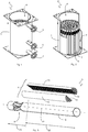
- FIG. 1 the housing 1 of a boiler 2 is shown in a perspective view, wherein in FIG. 2 the housing 1 is partially hidden to allow a better insight into the interior of the housing 1.
- the boiler 2 is used to heat heating water of a heating circuit, not shown, and can be designed as a condensing boiler.
- the housing 1 encloses a Schumacherraum 3 and further comprises a pot-shaped or conical combustion chamber 4, which is arranged above the Schwarzraumes 3 and is associated with a burner, not shown.
- a heat exchanger is arranged, which has a plurality of heat exchanger tubes 5, which pass through the Schwarzementraum 3 and open into an exhaust gas collecting chamber, not shown.
- the heat exchanger tubes 5 extend from the bottom of the combustion chamber 4 and extend in the shown embodiment substantially vertically through the heating water space 3, wherein alternatively also an arbitrary angle between 0 ° for a horizontal course and 90 ° for a vertical course of the heat exchanger tubes. 5 in Walkermoreraum is conceivable.
- the Schuwasserraum open return pipe 6 and 7, via the cooled return water of different heating circuits the Schuzierraum 3 is fed again.
- the heating circuit connected to the return pipe 6 serves, for example, the domestic water heating, so has a relatively high return temperature, while the lower return pipe 7 is connected to a heating circuit for example, a floor heating, so with a relatively low return temperature.
- the heated heating water for the heating circuits is removed via the upper supply pipe 8.
- FIG. 2 shows the heat exchanger tubes 5, which are formed according to the invention with indentations or in each case with a circumferential press-in 9 in its upper region.
- a single heat exchanger tube 5 according to the present invention is shown in a perspective partial view in FIG FIG. 3 to see.
- the heat exchanger tube 5 has an outer tube 10, which is flowed through in the operation of the boiler 2 by exhaust gases of the boiler furnace and the outside is surrounded by the heating water, and an inserted in the assembled state in the outer tube 10 profile insert 11.
- the outer tube 10 thus has an inlet serving for the supply of exhaust gases and serving for the discharge of exhaust gases Outlet, wherein the profile insert 11 is disposed at the outlet.
- the outer tube 10 is formed of a metallic alloy, preferably steel.
- the profile insert 11 has to increase the inner surface of the outer tube 10 in its longitudinal direction 12 extending ribs 14 and is in heat-conducting contact with the outer tube 10, wherein the profile insert 11 is formed of aluminum to improve the heat transfer.
- the profile insert 11 comprises a tubular body which is formed by two shell elements 15, 16.
- the two shell elements 15, 16 each have a semicircular cross-section. Conceivable, of course, would be a one-piece profile insert 11, which would not be inexpensive to produce. Therefore, an at least two-part profile insert 11 is more desirable, whose shell elements are formed in a circle-shaped, to give a closed profile insert 11.
- the tubular body thus comprises two shell elements 15, 16, which are formed at their contacting longitudinal edges 17 with groove-shaped recesses 18 and rib-like projections 19 and thus interlock sealingly, as in FIG. 4 is shown in an enlarged detail view.
- the two shell elements 15, 16 are formed on their inside with projecting into the clear cross section of the tubular body, in the longitudinal direction 12 of the outer tube 10 extending ribs 14, wherein each shell member 15, 16 forms a one-sided open profile with its ribs 14.
- the two shell elements 15, 16 are each formed on a longitudinal edge 12 with the recess 18 acting as a sealing groove and on the other longitudinal edge 12 with a sealing rib adapted in the form of a sealing groove, which is the projection 19.
- the assembled from the two shell elements 15, 16 profile insert 11 abuts directly on its entire peripheral surface on the outer tube 10 and is made with an outer diameter which is slightly smaller than the inner diameter of the outer tube 10, so that the Profile insert 11 can be easily inserted into the outer tube 10.
- FIG. 3 was to recognize the outer tube 10 and the profile insert 11 have a different axial length, which in the FIGS. 6 and 7 which shows various side views of the heat exchanger pipe 5 according to the invention, whereas FIG. 5 shows a single heat exchanger tube 5, in which the at the serving for the discharge of exhaust gas outlet of the outer tube 10 arranged profile insert 11 is inserted into the outer tube 10 and is not visible from the outside.
- the axial length 20 of the outer tube 10 ideally corresponds to 1.5 times the axial length 21 of the profile insert 11, wherein it is also conceivable that the axial length 20 of the outer tube 1.3 times or the 1st , 7 times the axial length 21 of the profile insert 11 corresponds.
- the different axial lengths 20, 21 of outer tube 10 and profile insert 11 cause the outer tube 10 can be divided into two longitudinal sections.
- a first longitudinal portion 22 of the outer tube 10 is formed cylindrically smooth-walled.
- a second longitudinal section 23 of the outer tube 10 has at least one cross-sectional constriction element 24 narrowing the throughflow cross section, which cross section is arranged on the inlet of the outer tube 10 serving for supplying exhaust gases.
- the axial length 25 of the first longitudinal section 22 is at least twice the axial length 26 of the axial length 25 of the first longitudinal section 22 second longitudinal section 23 corresponds.
- the axial length 26 of the second longitudinal section 23 is greater than the axial length 25 of the first longitudinal section 22nd
- FIG. 6 It is shown that the profile insert 11 is not flush with the outer tube 10, but a small piece is inserted into the outer tube 10, so that the profile insert 11 is completely absorbed by the outer tube 10 and in particular by the first longitudinal portion 22. Further, go out FIG. 6 combined with FIG. 2 that the second, the cross-sectional constriction member 24 having longitudinal portions 23 of the respective outer tubes 10 between the combustion chamber 4 and the respective first longitudinal portions 22 of the corresponding outer tubes 10 are arranged. Consequently, a respective cross-sectional constriction element 24 is arranged directly downstream of the combustion chamber 4.
- the cross-sectional constriction element 24 could be formed as a tubular insert formed in the manner of a nozzle, which is inserted into the second longitudinal section 23 of the outer tube 10.
- the outer tube 10 would be continuous smoothly formed both in the first and in the second longitudinal section 22, 23.
- the second longitudinal section 23 of the outer tube 10 pressings or indentations 9.
- the cross-sectional constriction member 24 comprises two first indentations 29, 30 which are formed in the wall of the second longitudinal section 23 of the outer tube 10.
- first indentations 29, 30 are pressed into the wall of the second longitudinal section 23, so that the first indentations 29, 30 represent concavely formed or inwardly arched indentations.
- the two first indentations 29, 30 are arranged diametrically opposite one another and are mirror-symmetrical with respect to the first pipe plane 27.
- a first Throughflow gap 31 (see FIG. 8 ) formed between 2% and 3% of the diameter 32 (see FIG. 6 ) of the outer tube 10 is as in FIG. 8 shown enlargement of the section A from FIG. 6 shows.
- the wall of the outer tube 10 is selectively pressed in from both sides of the tube, so that inwardly curved indentations are formed, which form the first throughflow gap 31 at the point of their smallest distance.
- the wall for the indentations 29, 30 over an axial length 33 (see FIG. 9 ), which corresponds to 0.4 times the axial length 26 of the second longitudinal section 23, wherein also an axial length 33 is possible, which corresponds to 0.3 times to 0.5 times the axial length 26.
- the wall is pressed on this axial length 33 of the deformation as a whole for the first indentations 29, 30, that the wall over the axial length 33 has a maximum diameter 34 for the first indentations 29, 30, which is 0.6 times the diameter 32 of the smooth-walled outer tube 10, wherein a maximum diameter 34 is possible, which corresponds to 0.5 times to 0.7 times the diameter 32 of the smooth-walled outer tube 10.
- FIGS. 7 and 9 show further representations for second indentations 35, 36, wherein the axial length 33 of the deformation for the first indentations 29, 30 and for the second indentations 35, 36 are ideally identical and therefore only in FIG. 9 is shown.
- the axial length of the deformation may also be different for first and second indentations.
- FIG. 7 is in addition to the profile insert 11 also shown an axial section FF, the in FIG. 11 is shown and the outer tube 10 and the two shell elements 15, 16 shows that form the profile insert 11.
- the two second recesses 35, 36 are diametrically opposite arranged, wherein they are formed with respect to the second pipe plane 28 mirror-symmetrical. Also, the second indentations 35, 36 are pressed into the wall of the second longitudinal section 23, so that they represent concave or inwardly arched pressings. Between the two second recesses 35, 36, a second flow-through gap 37 is formed, which is greater than the first flow-through gap 31 and between 18% and 22% of the diameter 32 (see FIG. 6 ) of the outer tube 10 is as in FIG. 9 shown enlargement of the section B from FIG. 7 shows.
- the wall of the outer tube 10 is selectively injected from both sides of the tube, so that inwardly curved indentations arise, which form the second flow gap 37 at the point of their smallest distance.
- the wall is for the indentations 35, 36 over the axial length 33 (see FIG. 9 ), which also corresponds to 0.4 times the axial length 26 of the second longitudinal section 23, wherein also an axial length 33 is possible, which corresponds to 0.3 times to 0.5 times the axial length 26.
- the wall is for the production of the second pressings or indentations 35, 36 on this axial length 33 pressed in total such that the wall over the axial length 33 has a maximum diameter 38 for the second indentations 35, 36, the 0.55- times the diameter 32 of the smooth-walled outer tube 10, wherein a maximum diameter 38 is possible, which corresponds to 0.45 times to 0.65 times the diameter 32 of the smooth-walled outer tube 10.
- FIG. 10 shows a flow cross-section 39, which in FIG. 10 with reference to the hatched area which characterizes the profile insert 11 formed from the shell elements 15, 16, and in FIG. 12 is shown by the black colored area. Since the first and second recesses 29, 30, 35, 36 are formed at a same axial position of the second longitudinal section 23 of the outer tube 10, ie, the first and second recesses 29, 30, 35, 36 both extend over the same axial length 33, the flow cross section 39 of the second longitudinal section 23 of the outer tube 10 formed by the first and second indentations 29, 30, 35, 36 has an H-shaped cross section.
- FIG. 13 shows the outer tube 10, in which a beginning of the H-shaped cross section pipe section is omitted, so that the H-shaped flow cross-section 39 is clearly visible.
- the cross-sectional constriction element 24 of the outer tube 10 constitutes a doubly symmetrical constriction, by means of which the disadvantages known from the prior art are avoided.
- the hot combustion gases flow through the heat exchanger tube from its inlet to its outlet and cool down.
- the concomitant and significant reduction in the volume of the combustion gases causes the flow rate and turbulence are greatly reduced to the outlet of the heat exchanger tube, which adversely affects the efficiency of heat transfer.
- Heat transfer is improved by the invention because the flow velocity and turbulence in the heat exchanger tube 5 according to the present invention are increased due to the cross-sectional constriction member 24 disposed at the inlet for supplying exhaust gases.
- the impressions or recesses 29, 30, 35, 36 increase the pressure loss in the upstream region before the pressings or indentations 29, 30, 35, 36.
- significantly more energy in the combustion chamber 4 and in the pipe section of the heat exchanger tube 5 before the indentations 29, 30, 35, 36 are transmitted.
- the flow velocity is massively increased by the constriction, which also increases the heat transfer and thus the energy use.
- the exhaust gas expands again and is guided into the section with the profile insert 11.
- the exhaust gas With the very large surface the ribs 14 of the profile insert 11, the exhaust gas is cooled to below the dew point and thus favors an advantage in condensing technology.
- the cross-sectional constriction element 24 (instead of the four press-fit) can be formed as only one indentation 9 in the wall of the second longitudinal section 23 of the outer tube 10 or several cross-sectional constrictions can be arranged through corresponding indentations 9 one behind the other in the axial direction 12 or at different axial tube positions ,
- the invention includes everything that is contained in the description and / or shown in the drawing, including what is obvious to those skilled deviating from the specific embodiments.
Landscapes
- Engineering & Computer Science (AREA)
- Physics & Mathematics (AREA)
- Thermal Sciences (AREA)
- Mechanical Engineering (AREA)
- General Engineering & Computer Science (AREA)
- Chemical & Material Sciences (AREA)
- Combustion & Propulsion (AREA)
- Geometry (AREA)
- Heat-Exchange Devices With Radiators And Conduit Assemblies (AREA)
- Details Of Fluid Heaters (AREA)
- Instantaneous Water Boilers, Portable Hot-Water Supply Apparatuses, And Control Of Portable Hot-Water Supply Apparatuses (AREA)
- Heat-Pump Type And Storage Water Heaters (AREA)
Priority Applications (6)
| Application Number | Priority Date | Filing Date | Title |
|---|---|---|---|
| ES17198940T ES2847858T3 (es) | 2015-07-23 | 2015-07-23 | Tubo de transferencia de calor y caldera con un tubo de transferencia de calor de este tipo |
| EP17198940.3A EP3301378B1 (fr) | 2015-07-23 | 2015-07-23 | Tuyau de transfert de chaleur et chaudière dotée d'un tel tuyau de transfert de chaleur |
| HUE17198940A HUE052530T2 (hu) | 2015-07-23 | 2015-07-23 | Hõátadó csõ és ilyen hõátadó csõvel rendelkezõ fûtõkazán |
| RS20210063A RS61336B1 (sr) | 2015-07-23 | 2015-07-23 | Toploizmenjivačka cev i zagrevni kotao sa takvom toploizmenjivačkom cevi |
| PL17198940T PL3301378T3 (pl) | 2015-07-23 | 2015-07-23 | Rura wymiennika ciepła i kocioł grzewczy z taką rurą wymiennika ciepła |
| HRP20210136TT HRP20210136T1 (hr) | 2015-07-23 | 2021-01-26 | Cijev za prijenos topline i kotao centralnog grijanja koji sadrži takvu cijev za prijenos topline |
Applications Claiming Priority (2)
| Application Number | Priority Date | Filing Date | Title |
|---|---|---|---|
| EP15178123.4A EP3040638B1 (fr) | 2015-07-23 | 2015-07-23 | Tuyau de transfert de chaleur et chaudiere dotee d'un tel tuyau de transfert de chaleur |
| EP17198940.3A EP3301378B1 (fr) | 2015-07-23 | 2015-07-23 | Tuyau de transfert de chaleur et chaudière dotée d'un tel tuyau de transfert de chaleur |
Related Parent Applications (2)
| Application Number | Title | Priority Date | Filing Date |
|---|---|---|---|
| EP15178123.4A Division EP3040638B1 (fr) | 2015-07-23 | 2015-07-23 | Tuyau de transfert de chaleur et chaudiere dotee d'un tel tuyau de transfert de chaleur |
| EP15178123.4A Division-Into EP3040638B1 (fr) | 2015-07-23 | 2015-07-23 | Tuyau de transfert de chaleur et chaudiere dotee d'un tel tuyau de transfert de chaleur |
Publications (2)
| Publication Number | Publication Date |
|---|---|
| EP3301378A1 true EP3301378A1 (fr) | 2018-04-04 |
| EP3301378B1 EP3301378B1 (fr) | 2020-12-30 |
Family
ID=53783074
Family Applications (2)
| Application Number | Title | Priority Date | Filing Date |
|---|---|---|---|
| EP15178123.4A Active EP3040638B1 (fr) | 2015-07-23 | 2015-07-23 | Tuyau de transfert de chaleur et chaudiere dotee d'un tel tuyau de transfert de chaleur |
| EP17198940.3A Active EP3301378B1 (fr) | 2015-07-23 | 2015-07-23 | Tuyau de transfert de chaleur et chaudière dotée d'un tel tuyau de transfert de chaleur |
Family Applications Before (1)
| Application Number | Title | Priority Date | Filing Date |
|---|---|---|---|
| EP15178123.4A Active EP3040638B1 (fr) | 2015-07-23 | 2015-07-23 | Tuyau de transfert de chaleur et chaudiere dotee d'un tel tuyau de transfert de chaleur |
Country Status (18)
| Country | Link |
|---|---|
| US (1) | US9739503B2 (fr) |
| EP (2) | EP3040638B1 (fr) |
| JP (2) | JP6318195B2 (fr) |
| KR (2) | KR101882928B1 (fr) |
| CN (2) | CN106370042B (fr) |
| AU (2) | AU2016204398B2 (fr) |
| CA (2) | CA2899479C (fr) |
| ES (2) | ES2672244T3 (fr) |
| HR (2) | HRP20180853T1 (fr) |
| HU (2) | HUE037245T2 (fr) |
| PL (2) | PL3301378T3 (fr) |
| PT (1) | PT3040638T (fr) |
| RS (2) | RS57268B1 (fr) |
| RU (2) | RU2682204C2 (fr) |
| SI (1) | SI3040638T1 (fr) |
| TR (1) | TR201807745T4 (fr) |
| TW (1) | TWI618909B (fr) |
| UA (2) | UA117507C2 (fr) |
Families Citing this family (11)
| Publication number | Priority date | Publication date | Assignee | Title |
|---|---|---|---|---|
| US20180372413A1 (en) | 2017-06-22 | 2018-12-27 | Rheem Manufacturing Company | Heat Exchanger Tubes And Tube Assembly Configurations |
| USD945579S1 (en) * | 2017-12-20 | 2022-03-08 | Rheem Manufacturing Company | Heat exchanger tube with fins |
| CA3089000A1 (fr) | 2018-01-19 | 2019-07-25 | Dri-Steem Corporation | Humidificateur avec determination automatique d'intervalle de vidange |
| US11421899B2 (en) * | 2018-01-19 | 2022-08-23 | Dri-Steem Corporation | Condensing, ultra-low NOx gas-fired humidifier |
| US10928140B2 (en) * | 2018-09-25 | 2021-02-23 | Giles Enterprises, Inc. | Baffle assembly and heat exchanger with expanding baffles |
| KR102120117B1 (ko) * | 2018-11-23 | 2020-06-09 | 주식회사 귀뚜라미 | 경사형 화실을 가지는 저탕식 보일러 |
| US20210302112A1 (en) * | 2018-12-19 | 2021-09-30 | Carrier Corporation | Heat exchanger with sacrificial turbulator |
| KR102173136B1 (ko) * | 2019-05-21 | 2020-11-02 | 최성환 | 보일러의 파형 연관 구조 |
| CN110749017A (zh) * | 2019-12-09 | 2020-02-04 | 佛山市顺德区雅洛特电器有限公司 | 顶置式上加水加湿器 |
| CN114087909B (zh) * | 2021-11-19 | 2022-10-25 | 西安交通大学 | 一种自振动内插折弯挠曲形翅片复合烟管 |
| US20250347441A1 (en) * | 2024-05-07 | 2025-11-13 | Aerco International, Inc. | Condensing boiler for use with non-condensing stacks |
Citations (5)
| Publication number | Priority date | Publication date | Assignee | Title |
|---|---|---|---|---|
| EP0752088A1 (fr) | 1994-03-24 | 1997-01-08 | Hoval Interliz Ag | Tube echangeur de chaleur pour chaudiere de chauffage |
| US5839505A (en) * | 1996-07-26 | 1998-11-24 | Aaon, Inc. | Dimpled heat exchange tube |
| EP2781873A1 (fr) | 2011-11-14 | 2014-09-24 | Choi, Sung-hwan | Tuyau d'échange de chaleur et méthode de fabrication de celui-ci |
| WO2015050441A1 (fr) * | 2013-10-02 | 2015-04-09 | Intergas Heating Assets B.V. | Tube pour un échangeur thermique avec une section transversale au moins partiellement variable, et échangeur thermique équipé d'un tel tube |
| KR101521353B1 (ko) * | 2013-12-03 | 2015-05-18 | 주식회사 에스엠아이 | 보일러 열교환기용 연관 제조 장치 |
Family Cites Families (35)
| Publication number | Priority date | Publication date | Assignee | Title |
|---|---|---|---|---|
| US1186573A (en) * | 1915-07-10 | 1916-06-13 | John T Haeusser | Tubular boiler. |
| US1549489A (en) * | 1918-10-26 | 1925-08-11 | Griscom Russell Co | Oil cooler |
| DE854224C (de) * | 1945-02-01 | 1952-10-30 | Siemens Ag | Waermeaustauscher fuer Gasturbinenanlagen |
| US3232280A (en) * | 1964-01-30 | 1966-02-01 | Cleaver Brooks Co | Heat exchange structure |
| US3724523A (en) * | 1970-06-29 | 1973-04-03 | Metallgesellschaft Ag | Tubular structure for film evaporators |
| JPS59100397A (ja) | 1982-11-04 | 1984-06-09 | イギリス国 | 熱伝達法 |
| JPS6099903A (ja) * | 1983-11-04 | 1985-06-03 | 旭硝子株式会社 | フエル−ル |
| JPS60162103A (ja) * | 1984-01-31 | 1985-08-23 | 旭硝子株式会社 | 改良されたフエル−ル |
| JPS61170803A (ja) | 1985-01-25 | 1986-08-01 | Hitachi Ltd | シ−ケンス制御方法 |
| NL8500393A (nl) * | 1985-02-12 | 1986-09-01 | Jogema Holding | Samengestelde buis voor het verwarmen van gassen. |
| JPS61170803U (fr) * | 1985-04-05 | 1986-10-23 | ||
| HU199979B (en) * | 1986-04-21 | 1990-03-28 | Energiagazdalkodasi Intezet | Method and heat-exchanger insert for improving the heat transfer of media flowing in the tubes of heat exchanger and having inhomogeneous composition and/or inhomogeneous physical state |
| SU1386844A1 (ru) * | 1986-10-28 | 1988-04-07 | Одесский Технологический Институт Холодильной Промышленности | Теплообменна труба |
| JPS6438590A (en) * | 1987-08-04 | 1989-02-08 | Toshiba Corp | Heat exchanger |
| RU2059184C1 (ru) * | 1992-07-31 | 1996-04-27 | Ерченко Герман Николаевич | Вертикальный теплообменный элемент коденсатора |
| DE4311034A1 (de) | 1993-04-03 | 1994-10-06 | Veba Oel Ag | Verfahren zur Gewinnung von Chemierohstoffen und Kraftstoffkomponenten aus Alt- oder Abfallkunststoff |
| JPH0771840A (ja) | 1993-09-02 | 1995-03-17 | Hitachi Ltd | 煙管式高温再生器 |
| JPH07119909A (ja) * | 1993-10-21 | 1995-05-12 | Miura Co Ltd | 煙管ボイラ |
| JPH07119903A (ja) * | 1993-10-21 | 1995-05-12 | Miura Co Ltd | 煙管ボイラ |
| JPH09203501A (ja) * | 1996-01-26 | 1997-08-05 | Nippon Furnace Kogyo Kaisha Ltd | 小型貫流ボイラ |
| CA2211983C (fr) * | 1997-02-28 | 2006-03-14 | Miura Co., Ltd. | Chaudiere a tubes d'eau |
| JPH11132404A (ja) * | 1997-10-31 | 1999-05-21 | Miura Co Ltd | 水管ボイラ |
| JPH11351696A (ja) * | 1998-06-11 | 1999-12-24 | Mitsubishi Heavy Ind Ltd | 熱交換器及び再生器及び吸収冷凍機 |
| US8459342B2 (en) * | 2003-11-25 | 2013-06-11 | Beckett Gas, Inc. | Heat exchanger tube with integral restricting and turbulating structure |
| CA2289428C (fr) * | 1998-12-04 | 2008-12-09 | Beckett Gas, Inc. | Tube d'echangeur de chaleur comprenant une structure integrale de limitation et de turbulence |
| US7171956B2 (en) * | 2002-08-28 | 2007-02-06 | T. Rad Co., Ltd. | EGR cooler |
| JP2004293782A (ja) * | 2003-03-07 | 2004-10-21 | Mitsuboshi Co Ltd | 異形チューブおよびそれを用いた流体装置 |
| CA2551646C (fr) * | 2004-01-05 | 2013-07-02 | Cooper-Standard Automotive, Inc. | Tuyau dente pour echangeur thermique |
| US6945320B2 (en) * | 2004-01-26 | 2005-09-20 | Lennox Manufacturing Inc. | Tubular heat exchanger with offset interior dimples |
| CN201306962Y (zh) * | 2008-11-19 | 2009-09-09 | 南通华信中央空调有限公司 | 热交换器的凹陷型热交换管 |
| JP5730059B2 (ja) * | 2010-02-19 | 2015-06-03 | タニコー株式会社 | 熱交換器及び熱交換器を用いた加熱装置 |
| DE102010038883C5 (de) * | 2010-08-04 | 2021-05-20 | Siemens Energy Global GmbH & Co. KG | Zwangdurchlaufdampferzeuger |
| US20140131021A1 (en) * | 2012-11-15 | 2014-05-15 | Sung-hwan Choi | Heat exchanger pipe and manufacturing method therefor |
| CN203011221U (zh) | 2012-12-22 | 2013-06-19 | 天津天雷科技有限公司 | 一种新型换热管内的喷嘴装置 |
| KR101427045B1 (ko) * | 2013-04-30 | 2014-08-05 | 최성환 | 2개의 반부 쉘이 일체로 연결된 열교환핀 및 그를 포함한 열교환관 |
-
2015
- 2015-07-23 PL PL17198940T patent/PL3301378T3/pl unknown
- 2015-07-23 EP EP15178123.4A patent/EP3040638B1/fr active Active
- 2015-07-23 PL PL15178123T patent/PL3040638T3/pl unknown
- 2015-07-23 ES ES15178123.4T patent/ES2672244T3/es active Active
- 2015-07-23 TR TR2018/07745T patent/TR201807745T4/tr unknown
- 2015-07-23 RS RS20180648A patent/RS57268B1/sr unknown
- 2015-07-23 SI SI201530255T patent/SI3040638T1/en unknown
- 2015-07-23 PT PT151781234T patent/PT3040638T/pt unknown
- 2015-07-23 HU HUE15178123A patent/HUE037245T2/hu unknown
- 2015-07-23 ES ES17198940T patent/ES2847858T3/es active Active
- 2015-07-23 HU HUE17198940A patent/HUE052530T2/hu unknown
- 2015-07-23 EP EP17198940.3A patent/EP3301378B1/fr active Active
- 2015-07-23 RS RS20210063A patent/RS61336B1/sr unknown
- 2015-08-06 CA CA2899479A patent/CA2899479C/fr active Active
- 2015-08-06 CA CA2998329A patent/CA2998329C/fr active Active
- 2015-08-26 US US14/836,167 patent/US9739503B2/en active Active
-
2016
- 2016-06-24 TW TW105120013A patent/TWI618909B/zh active
- 2016-06-24 JP JP2016125408A patent/JP6318195B2/ja active Active
- 2016-06-27 AU AU2016204398A patent/AU2016204398B2/en not_active Ceased
- 2016-07-20 CN CN201610575293.5A patent/CN106370042B/zh active Active
- 2016-07-20 CN CN201810134877.8A patent/CN108426478B/zh active Active
- 2016-07-21 UA UAA201608061A patent/UA117507C2/uk unknown
- 2016-07-21 UA UAA201801572A patent/UA120547C2/uk unknown
- 2016-07-22 RU RU2018105848A patent/RU2682204C2/ru active
- 2016-07-22 RU RU2016130039A patent/RU2647012C2/ru active
- 2016-07-22 KR KR1020160093749A patent/KR101882928B1/ko active Active
-
2017
- 2017-10-11 AU AU2017245359A patent/AU2017245359B2/en not_active Ceased
-
2018
- 2018-03-06 JP JP2018039460A patent/JP6514798B2/ja active Active
- 2018-04-12 KR KR1020180042959A patent/KR101956378B1/ko active Active
- 2018-05-29 HR HRP20180853TT patent/HRP20180853T1/hr unknown
-
2021
- 2021-01-26 HR HRP20210136TT patent/HRP20210136T1/hr unknown
Patent Citations (5)
| Publication number | Priority date | Publication date | Assignee | Title |
|---|---|---|---|---|
| EP0752088A1 (fr) | 1994-03-24 | 1997-01-08 | Hoval Interliz Ag | Tube echangeur de chaleur pour chaudiere de chauffage |
| US5839505A (en) * | 1996-07-26 | 1998-11-24 | Aaon, Inc. | Dimpled heat exchange tube |
| EP2781873A1 (fr) | 2011-11-14 | 2014-09-24 | Choi, Sung-hwan | Tuyau d'échange de chaleur et méthode de fabrication de celui-ci |
| WO2015050441A1 (fr) * | 2013-10-02 | 2015-04-09 | Intergas Heating Assets B.V. | Tube pour un échangeur thermique avec une section transversale au moins partiellement variable, et échangeur thermique équipé d'un tel tube |
| KR101521353B1 (ko) * | 2013-12-03 | 2015-05-18 | 주식회사 에스엠아이 | 보일러 열교환기용 연관 제조 장치 |
Also Published As
Similar Documents
| Publication | Publication Date | Title |
|---|---|---|
| EP3040638B1 (fr) | Tuyau de transfert de chaleur et chaudiere dotee d'un tel tuyau de transfert de chaleur | |
| EP2546573B1 (fr) | Vehicle heating device | |
| EP2413080A2 (fr) | Dispositif de refroidissement pour un moteur à combustion interne | |
| DE60305277T2 (de) | Effizienter Wärmetauscher und Brennkammer-Anordnung für Kessel und Lufterhitzer | |
| WO1992020975A1 (fr) | Appareil de chauffage d'air | |
| DE112013007041T5 (de) | Wärmetauscher | |
| EP1899654B1 (fr) | Chaudière de chauffage | |
| EP2096372A2 (fr) | Appareil de chauffage | |
| DE212013000202U1 (de) | Heißluftofen | |
| DE2645717A1 (de) | Heizkessel zum verbrennen von fluessigen oder gasfoermigen brennstoffen | |
| EP1445552B1 (fr) | Installation de chauffage de voitures | |
| EP0128463A2 (fr) | Appareil de chauffage des locaux pour des locaux de petite dimension | |
| DE102018117213A1 (de) | Fahrzeugheizgerät | |
| DE102005001662A1 (de) | Wärmetauscherkörper und Fahrzeugheizgerät mit einem Wärmetauscherkörper | |
| DE102007041338B3 (de) | Wärmeübertragungseinheit für eine Verbrennungskraftmaschine | |
| DE102011081401B4 (de) | Wärmetauscheranordnung, insbesondere für ein brennstoffbetriebenes Fahrzeugheizgerät | |
| DE102013111773A1 (de) | Heizkessel | |
| EP2306112A1 (fr) | Appareil de chauffage | |
| DE1190155B (de) | Heizkessel zum Verfeuern fluessiger oder gasfoermiger Brennstoffe | |
| DE10203116B4 (de) | Heizgerät mit einem becherförmigen Wärmeübertrager | |
| EP3096093B1 (fr) | Appareil de chauffage | |
| DE102005004740B3 (de) | Wärmetauscher mit optimierten Wärmeübertragungselementen | |
| DE102010001635A1 (de) | Wärmeübertrager | |
| EP0345683A2 (fr) | Chaudière de chauffage pour brûler des combustibles liquides ou gazeux | |
| DE202014010537U1 (de) | Heizgerät |
Legal Events
| Date | Code | Title | Description |
|---|---|---|---|
| PUAI | Public reference made under article 153(3) epc to a published international application that has entered the european phase |
Free format text: ORIGINAL CODE: 0009012 |
|
| STAA | Information on the status of an ep patent application or granted ep patent |
Free format text: STATUS: THE APPLICATION HAS BEEN PUBLISHED |
|
| AC | Divisional application: reference to earlier application |
Ref document number: 3040638 Country of ref document: EP Kind code of ref document: P |
|
| AK | Designated contracting states |
Kind code of ref document: A1 Designated state(s): AL AT BE BG CH CY CZ DE DK EE ES FI FR GB GR HR HU IE IS IT LI LT LU LV MC MK MT NL NO PL PT RO RS SE SI SK SM TR |
|
| AX | Request for extension of the european patent |
Extension state: BA ME |
|
| STAA | Information on the status of an ep patent application or granted ep patent |
Free format text: STATUS: REQUEST FOR EXAMINATION WAS MADE |
|
| 17P | Request for examination filed |
Effective date: 20181004 |
|
| RBV | Designated contracting states (corrected) |
Designated state(s): AL AT BE BG CH CY CZ DE DK EE ES FI FR GB GR HR HU IE IS IT LI LT LU LV MC MK MT NL NO PL PT RO RS SE SI SK SM TR |
|
| GRAP | Despatch of communication of intention to grant a patent |
Free format text: ORIGINAL CODE: EPIDOSNIGR1 |
|
| STAA | Information on the status of an ep patent application or granted ep patent |
Free format text: STATUS: GRANT OF PATENT IS INTENDED |
|
| RIC1 | Information provided on ipc code assigned before grant |
Ipc: F24H 1/28 20060101AFI20200915BHEP Ipc: F24H 1/20 20060101ALI20200915BHEP Ipc: F24H 9/00 20060101ALI20200915BHEP Ipc: F24H 8/00 20060101ALI20200915BHEP Ipc: F28F 1/06 20060101ALI20200915BHEP Ipc: F28F 1/00 20060101ALI20200915BHEP Ipc: F28F 1/40 20060101ALI20200915BHEP |
|
| INTG | Intention to grant announced |
Effective date: 20201021 |
|
| GRAS | Grant fee paid |
Free format text: ORIGINAL CODE: EPIDOSNIGR3 |
|
| GRAA | (expected) grant |
Free format text: ORIGINAL CODE: 0009210 |
|
| STAA | Information on the status of an ep patent application or granted ep patent |
Free format text: STATUS: THE PATENT HAS BEEN GRANTED |
|
| AC | Divisional application: reference to earlier application |
Ref document number: 3040638 Country of ref document: EP Kind code of ref document: P |
|
| AK | Designated contracting states |
Kind code of ref document: B1 Designated state(s): AL AT BE BG CH CY CZ DE DK EE ES FI FR GB GR HR HU IE IS IT LI LT LU LV MC MK MT NL NO PL PT RO RS SE SI SK SM TR |
|
| REG | Reference to a national code |
Ref country code: GB Ref legal event code: FG4D Free format text: NOT ENGLISH |
|
| REG | Reference to a national code |
Ref country code: DE Ref legal event code: R096 Ref document number: 502015014098 Country of ref document: DE |
|
| REG | Reference to a national code |
Ref country code: AT Ref legal event code: REF Ref document number: 1350326 Country of ref document: AT Kind code of ref document: T Effective date: 20210115 |
|
| REG | Reference to a national code |
Ref country code: HR Ref legal event code: TUEP Ref document number: P20210136T Country of ref document: HR |
|
| REG | Reference to a national code |
Ref country code: RO Ref legal event code: EPE |
|
| REG | Reference to a national code |
Ref country code: IE Ref legal event code: FG4D Free format text: LANGUAGE OF EP DOCUMENT: GERMAN |
|
| REG | Reference to a national code |
Ref country code: NL Ref legal event code: FP |
|
| REG | Reference to a national code |
Ref country code: SK Ref legal event code: T3 Ref document number: E 36295 Country of ref document: SK |
|
| PG25 | Lapsed in a contracting state [announced via postgrant information from national office to epo] |
Ref country code: FI Free format text: LAPSE BECAUSE OF FAILURE TO SUBMIT A TRANSLATION OF THE DESCRIPTION OR TO PAY THE FEE WITHIN THE PRESCRIBED TIME-LIMIT Effective date: 20201230 Ref country code: GR Free format text: LAPSE BECAUSE OF FAILURE TO SUBMIT A TRANSLATION OF THE DESCRIPTION OR TO PAY THE FEE WITHIN THE PRESCRIBED TIME-LIMIT Effective date: 20210331 Ref country code: NO Free format text: LAPSE BECAUSE OF FAILURE TO SUBMIT A TRANSLATION OF THE DESCRIPTION OR TO PAY THE FEE WITHIN THE PRESCRIBED TIME-LIMIT Effective date: 20210330 |
|
| REG | Reference to a national code |
Ref country code: HR Ref legal event code: T1PR Ref document number: P20210136 Country of ref document: HR Ref country code: HU Ref legal event code: AG4A Ref document number: E052530 Country of ref document: HU |
|
| PG25 | Lapsed in a contracting state [announced via postgrant information from national office to epo] |
Ref country code: SE Free format text: LAPSE BECAUSE OF FAILURE TO SUBMIT A TRANSLATION OF THE DESCRIPTION OR TO PAY THE FEE WITHIN THE PRESCRIBED TIME-LIMIT Effective date: 20201230 Ref country code: LV Free format text: LAPSE BECAUSE OF FAILURE TO SUBMIT A TRANSLATION OF THE DESCRIPTION OR TO PAY THE FEE WITHIN THE PRESCRIBED TIME-LIMIT Effective date: 20201230 |
|
| REG | Reference to a national code |
Ref country code: LT Ref legal event code: MG9D |
|
| PG25 | Lapsed in a contracting state [announced via postgrant information from national office to epo] |
Ref country code: PT Free format text: LAPSE BECAUSE OF FAILURE TO SUBMIT A TRANSLATION OF THE DESCRIPTION OR TO PAY THE FEE WITHIN THE PRESCRIBED TIME-LIMIT Effective date: 20210430 Ref country code: EE Free format text: LAPSE BECAUSE OF FAILURE TO SUBMIT A TRANSLATION OF THE DESCRIPTION OR TO PAY THE FEE WITHIN THE PRESCRIBED TIME-LIMIT Effective date: 20201230 Ref country code: LT Free format text: LAPSE BECAUSE OF FAILURE TO SUBMIT A TRANSLATION OF THE DESCRIPTION OR TO PAY THE FEE WITHIN THE PRESCRIBED TIME-LIMIT Effective date: 20201230 |
|
| REG | Reference to a national code |
Ref country code: ES Ref legal event code: FG2A Ref document number: 2847858 Country of ref document: ES Kind code of ref document: T3 Effective date: 20210804 |
|
| REG | Reference to a national code |
Ref country code: HR Ref legal event code: ODRP Ref document number: P20210136 Country of ref document: HR Payment date: 20210720 Year of fee payment: 7 |
|
| PG25 | Lapsed in a contracting state [announced via postgrant information from national office to epo] |
Ref country code: IS Free format text: LAPSE BECAUSE OF FAILURE TO SUBMIT A TRANSLATION OF THE DESCRIPTION OR TO PAY THE FEE WITHIN THE PRESCRIBED TIME-LIMIT Effective date: 20210430 |
|
| REG | Reference to a national code |
Ref country code: DE Ref legal event code: R097 Ref document number: 502015014098 Country of ref document: DE |
|
| PG25 | Lapsed in a contracting state [announced via postgrant information from national office to epo] |
Ref country code: AL Free format text: LAPSE BECAUSE OF FAILURE TO SUBMIT A TRANSLATION OF THE DESCRIPTION OR TO PAY THE FEE WITHIN THE PRESCRIBED TIME-LIMIT Effective date: 20201230 |
|
| PGFP | Annual fee paid to national office [announced via postgrant information from national office to epo] |
Ref country code: LU Payment date: 20210726 Year of fee payment: 7 |
|
| PLBE | No opposition filed within time limit |
Free format text: ORIGINAL CODE: 0009261 |
|
| STAA | Information on the status of an ep patent application or granted ep patent |
Free format text: STATUS: NO OPPOSITION FILED WITHIN TIME LIMIT |
|
| PG25 | Lapsed in a contracting state [announced via postgrant information from national office to epo] |
Ref country code: DK Free format text: LAPSE BECAUSE OF FAILURE TO SUBMIT A TRANSLATION OF THE DESCRIPTION OR TO PAY THE FEE WITHIN THE PRESCRIBED TIME-LIMIT Effective date: 20201230 |
|
| PGFP | Annual fee paid to national office [announced via postgrant information from national office to epo] |
Ref country code: ES Payment date: 20210928 Year of fee payment: 7 Ref country code: RS Payment date: 20210722 Year of fee payment: 7 Ref country code: BE Payment date: 20210721 Year of fee payment: 7 |
|
| 26N | No opposition filed |
Effective date: 20211001 |
|
| PG25 | Lapsed in a contracting state [announced via postgrant information from national office to epo] |
Ref country code: SI Free format text: LAPSE BECAUSE OF FAILURE TO SUBMIT A TRANSLATION OF THE DESCRIPTION OR TO PAY THE FEE WITHIN THE PRESCRIBED TIME-LIMIT Effective date: 20201230 |
|
| PG25 | Lapsed in a contracting state [announced via postgrant information from national office to epo] |
Ref country code: MC Free format text: LAPSE BECAUSE OF FAILURE TO SUBMIT A TRANSLATION OF THE DESCRIPTION OR TO PAY THE FEE WITHIN THE PRESCRIBED TIME-LIMIT Effective date: 20201230 |
|
| PG25 | Lapsed in a contracting state [announced via postgrant information from national office to epo] |
Ref country code: IS Free format text: LAPSE BECAUSE OF FAILURE TO SUBMIT A TRANSLATION OF THE DESCRIPTION OR TO PAY THE FEE WITHIN THE PRESCRIBED TIME-LIMIT Effective date: 20210430 |
|
| PG25 | Lapsed in a contracting state [announced via postgrant information from national office to epo] |
Ref country code: IE Free format text: LAPSE BECAUSE OF NON-PAYMENT OF DUE FEES Effective date: 20210723 |
|
| REG | Reference to a national code |
Ref country code: HR Ref legal event code: ODRP Ref document number: P20210136 Country of ref document: HR Payment date: 20220718 Year of fee payment: 8 |
|
| REG | Reference to a national code |
Ref country code: BE Ref legal event code: MM Effective date: 20220731 |
|
| PG25 | Lapsed in a contracting state [announced via postgrant information from national office to epo] |
Ref country code: LU Free format text: LAPSE BECAUSE OF NON-PAYMENT OF DUE FEES Effective date: 20220723 |
|
| PG25 | Lapsed in a contracting state [announced via postgrant information from national office to epo] |
Ref country code: RS Free format text: LAPSE BECAUSE OF NON-PAYMENT OF DUE FEES Effective date: 20220723 Ref country code: BE Free format text: LAPSE BECAUSE OF NON-PAYMENT OF DUE FEES Effective date: 20220731 |
|
| PG25 | Lapsed in a contracting state [announced via postgrant information from national office to epo] |
Ref country code: CY Free format text: LAPSE BECAUSE OF FAILURE TO SUBMIT A TRANSLATION OF THE DESCRIPTION OR TO PAY THE FEE WITHIN THE PRESCRIBED TIME-LIMIT Effective date: 20201230 |
|
| PG25 | Lapsed in a contracting state [announced via postgrant information from national office to epo] |
Ref country code: SM Free format text: LAPSE BECAUSE OF FAILURE TO SUBMIT A TRANSLATION OF THE DESCRIPTION OR TO PAY THE FEE WITHIN THE PRESCRIBED TIME-LIMIT Effective date: 20201230 |
|
| REG | Reference to a national code |
Ref country code: HR Ref legal event code: ODRP Ref document number: P20210136 Country of ref document: HR Payment date: 20230719 Year of fee payment: 9 |
|
| P01 | Opt-out of the competence of the unified patent court (upc) registered |
Effective date: 20230704 |
|
| REG | Reference to a national code |
Ref country code: ES Ref legal event code: FD2A Effective date: 20230901 |
|
| PG25 | Lapsed in a contracting state [announced via postgrant information from national office to epo] |
Ref country code: ES Free format text: LAPSE BECAUSE OF NON-PAYMENT OF DUE FEES Effective date: 20220724 |
|
| PG25 | Lapsed in a contracting state [announced via postgrant information from national office to epo] |
Ref country code: MK Free format text: LAPSE BECAUSE OF FAILURE TO SUBMIT A TRANSLATION OF THE DESCRIPTION OR TO PAY THE FEE WITHIN THE PRESCRIBED TIME-LIMIT Effective date: 20201230 |
|
| PG25 | Lapsed in a contracting state [announced via postgrant information from national office to epo] |
Ref country code: TR Free format text: LAPSE BECAUSE OF FAILURE TO SUBMIT A TRANSLATION OF THE DESCRIPTION OR TO PAY THE FEE WITHIN THE PRESCRIBED TIME-LIMIT Effective date: 20201230 |
|
| REG | Reference to a national code |
Ref country code: HR Ref legal event code: ODRP Ref document number: P20210136 Country of ref document: HR Payment date: 20240711 Year of fee payment: 10 |
|
| PG25 | Lapsed in a contracting state [announced via postgrant information from national office to epo] |
Ref country code: MT Free format text: LAPSE BECAUSE OF FAILURE TO SUBMIT A TRANSLATION OF THE DESCRIPTION OR TO PAY THE FEE WITHIN THE PRESCRIBED TIME-LIMIT Effective date: 20201230 |
|
| PGFP | Annual fee paid to national office [announced via postgrant information from national office to epo] |
Ref country code: HU Payment date: 20250723 Year of fee payment: 11 |
|
| REG | Reference to a national code |
Ref country code: HR Ref legal event code: ODRP Ref document number: P20210136 Country of ref document: HR Payment date: 20250711 Year of fee payment: 11 |
|
| PGFP | Annual fee paid to national office [announced via postgrant information from national office to epo] |
Ref country code: NL Payment date: 20250721 Year of fee payment: 11 |
|
| PGFP | Annual fee paid to national office [announced via postgrant information from national office to epo] |
Ref country code: DE Payment date: 20250731 Year of fee payment: 11 |
|
| PGFP | Annual fee paid to national office [announced via postgrant information from national office to epo] |
Ref country code: PL Payment date: 20250711 Year of fee payment: 11 Ref country code: IT Payment date: 20250724 Year of fee payment: 11 |
|
| PGFP | Annual fee paid to national office [announced via postgrant information from national office to epo] |
Ref country code: BG Payment date: 20250722 Year of fee payment: 11 Ref country code: GB Payment date: 20250722 Year of fee payment: 11 |
|
| PGFP | Annual fee paid to national office [announced via postgrant information from national office to epo] |
Ref country code: HR Payment date: 20250711 Year of fee payment: 11 |
|
| PGFP | Annual fee paid to national office [announced via postgrant information from national office to epo] |
Ref country code: FR Payment date: 20250725 Year of fee payment: 11 Ref country code: AT Payment date: 20250722 Year of fee payment: 11 |
|
| PGFP | Annual fee paid to national office [announced via postgrant information from national office to epo] |
Ref country code: CH Payment date: 20250801 Year of fee payment: 11 |
|
| PGFP | Annual fee paid to national office [announced via postgrant information from national office to epo] |
Ref country code: CZ Payment date: 20250715 Year of fee payment: 11 |
|
| PGFP | Annual fee paid to national office [announced via postgrant information from national office to epo] |
Ref country code: RO Payment date: 20250716 Year of fee payment: 11 |
|
| PGFP | Annual fee paid to national office [announced via postgrant information from national office to epo] |
Ref country code: SK Payment date: 20250716 Year of fee payment: 11 |