EP3301797A1 - Läufer eines linearmotorbasiertes transportsystems, linearmo-torbasiertes transportsystem und verfahren - Google Patents
Läufer eines linearmotorbasiertes transportsystems, linearmo-torbasiertes transportsystem und verfahren Download PDFInfo
- Publication number
- EP3301797A1 EP3301797A1 EP16191738.0A EP16191738A EP3301797A1 EP 3301797 A1 EP3301797 A1 EP 3301797A1 EP 16191738 A EP16191738 A EP 16191738A EP 3301797 A1 EP3301797 A1 EP 3301797A1
- Authority
- EP
- European Patent Office
- Prior art keywords
- detection element
- rotor
- segment
- sensor
- linear motor
- Prior art date
- Legal status (The legal status is an assumption and is not a legal conclusion. Google has not performed a legal analysis and makes no representation as to the accuracy of the status listed.)
- Withdrawn
Links
- 238000001514 detection method Methods 0.000 claims abstract description 164
- 238000000034 method Methods 0.000 claims abstract description 9
- 238000011156 evaluation Methods 0.000 claims description 31
- 230000007704 transition Effects 0.000 claims description 22
- 230000033001 locomotion Effects 0.000 claims description 17
- 230000003993 interaction Effects 0.000 claims description 6
- 230000001276 controlling effect Effects 0.000 claims description 2
- 238000004806 packaging method and process Methods 0.000 claims description 2
- 230000001105 regulatory effect Effects 0.000 claims description 2
- 239000004020 conductor Substances 0.000 description 2
- 238000003491 array Methods 0.000 description 1
- 230000001419 dependent effect Effects 0.000 description 1
- 238000011161 development Methods 0.000 description 1
- 230000018109 developmental process Effects 0.000 description 1
- 238000006073 displacement reaction Methods 0.000 description 1
- 230000002349 favourable effect Effects 0.000 description 1
- 230000036962 time dependent Effects 0.000 description 1
Images

Classifications
-
- H—ELECTRICITY
- H02—GENERATION; CONVERSION OR DISTRIBUTION OF ELECTRIC POWER
- H02K—DYNAMO-ELECTRIC MACHINES
- H02K41/00—Propulsion systems in which a rigid body is moved along a path due to dynamo-electric interaction between the body and a magnetic field travelling along the path
- H02K41/02—Linear motors; Sectional motors
-
- H—ELECTRICITY
- H02—GENERATION; CONVERSION OR DISTRIBUTION OF ELECTRIC POWER
- H02K—DYNAMO-ELECTRIC MACHINES
- H02K11/00—Structural association of dynamo-electric machines with electric components or with devices for shielding, monitoring or protection
- H02K11/20—Structural association of dynamo-electric machines with electric components or with devices for shielding, monitoring or protection for measuring, monitoring, testing, protecting or switching
- H02K11/21—Devices for sensing speed or position, or actuated thereby
Definitions
- the invention relates to a rotor of a linear motor-based transport system and a linear motor-based transport system. Furthermore, the invention relates to a method for operating a linear motor-based transport system. Furthermore, the invention relates to a system with a linear motor-based transport system.
- Linear motor-based transport systems have runners.
- a linear motor-based transport system is understood to mean a transport system in which the runners are moved at least in regions by means of linear motor stators, so-called segments.
- An example of such a linear motor-based transport system is the multi-carrier system from Siemens and FESTO.
- the runners regularly have a detection element, in particular a magnetic element.
- the sensing element cooperates with a sensor associated with a segment of the linear motor based transport system. Through the interaction of the sensing element and the sensor, the position of the rotor on the segment can be determined.
- Linear motor-based transport systems often have several segments, wherein the at least one runner is moved over a plurality of segments. In the transition of the rotor from one segment to another segment occasionally difficulties arise, which must be compensated with complex control circuits.
- the object is further achieved with a linear-based transport system according to claim 5.
- the object is also achieved with a method for operating a linear-based transport system according to claim 11.
- the rotor is designed for a linear motor-based transport system.
- the rotor has a first detection element and at least one second detection element, wherein the respective detection element is designed to detect the position of the rotor, wherein the first detection element and at least the second detection element are spaced from the rotor.
- the first detection element can be detected by a first sensor of the linear motor-based transport system and / or the second detection element can be detected by a second sensor of the linear motor-based transport system.
- the rotor may also have three, four or more detection elements, wherein the detection elements are arranged spaced on a respective longitudinal side, in particular in a provided direction of movement of the rotor. Further, a rotor may be disposed on the spaced-apart detection elements on both sides extending in the direction of movement.
- the linear motor-based transport system has a first segment and at least a second segment and a drive control, wherein the segments are arranged sequentially, wherein the respective segment is associated with a respective sensor.
- the linear motor-based transport system further comprises at least one rotor according to one of the preceding claims, wherein the drive control is designed to control and / or regulating the movement of the rotor.
- the first detection element and the second detection element are detected by the sensor of the respective segment.
- the first detection element is detected by the sensor of the first segment and the second detection element is detected by the sensor of the second segment.
- a runner can also have more than two detection elements.
- the detection elements are then spaced from each other arranged on the rotor.
- the respective first segment and the respective second segment are adjacent, in particular consecutive, arranged.
- the detection element is preferably designed as a magnetic element, as an electrode or as a light source.
- the sensor of the respective segment is exemplified as a magnetostriction sensor, as a Hall sensor, in particular as an array of Hall sensors, as an electrical conductor, in particular as a resistive electrical conductor, as a light sensor, in particular as a photodiode.
- the respective detection element is arranged near a side wall of the rotor.
- the sensor is preferably attached to the segment according to the position of the detection element.
- the sensor serves to detect the position and / or the speed of the respective rotor.
- the linear transport system serves to position a runner or a plurality of runners on a web, wherein the web is preferably defined by the arrangement of the segments.
- the detection elements are arranged near the same side of the rotor.
- the sensor can also be arranged on the same side of the respective segment.
- both detection elements are detected with the sensor of the respective segment.
- the runners are the same.
- the distance from each other and / or the position of the detection elements on the respective rotor are the same in each case.
- the detection elements can be assigned to a respective runner.
- the distance of the detection elements chosen to be sufficiently small, so that at a spaced displacement of a plurality of runners with the same distance the detection elements are assigned to the respective runners.
- the detected position of the respective runner is transmitted to a drive control.
- the drive control controls and / or regulates the position and / or the speed of the respective runner on the basis of the detected position of the respective runner.
- a detection of the position or the speed of the respective runner without interruptions.
- errors in the determination of the location or the speed can be corrected.
- the sensor of the segment detects the first detection element and the second detection element.
- a transition of a rotor from a first segment to another segment can be determined by the detection of only one of the respective detection element by the respective sensor.
- the first detection element and the second detection element are spaced along a direction of movement of the rotor.
- the detection elements may be arranged offset, but are preferably arranged in the direction of movement spaced from the rotor.
- the respective sensor of the respective segment can advantageously be attached to one side in each case.
- two detection elements in particular permanent magnets, are preferably positioned near the respective longitudinal sides of the rotor.
- the detection elements are spaced in this embodiment in the longitudinal direction of the rotor.
- the respective detection element is designed in each case as a magnetic element, as an electrode or as a lighting means.
- the detection element can be designed, for example, as a light-emitting diode (LED) or as a permanent magnet.
- the sensor can preferably be designed as an array of photosensors (phototransistors, photoresistors or photodiodes), the position of the respective luminous means being determined with the aid of the array.
- the light-emitting means is preferably arranged on the rotor. Furthermore, the sensor is arranged on the respective rotor.
- the electrode When using an electrode as a detection element, the electrode may be formed with a current collector.
- electrical energy can be transmitted simultaneously from sensor to the detection element and thus to the rotor.
- a battery or a battery into consideration which is arranged on / in the rotor.
- the first detection element and the second detection element have a different interaction strength with the respective sensor.
- the first detection element For detecting the alignment, it is possible to form the first detection element as a strong permanent magnet and the second detection element as a weak permanent magnet. The sensor then detects whether the first detection element or the second detection element is detected in the direction of movement.
- the orientation of the rotor can be preferably determined.
- the segments are preferably designed as linear motor stators.
- the segments are arranged such that a linear movement possibility of the rotor extends to a plurality of the segments.
- the Linearmotorstator en form by the juxtaposed arrangement, at least mechanically, a long linear motor stator-corresponding unit.
- the movement of the respective runner on the plurality of successive segments can be described as a movement on a (extended) segment.
- the rotor on permanent magnets, which interact with current-carrying coils of the segments.
- the rotor is moved on the segment.
- the current flow through the coils of the respective segment is provided by a drive control.
- the drive controller preferably has a motion control and / or a programmable logic controller (PLC) and a plurality of power converters.
- PLC programmable logic controller
- each segment is assigned a power converter.
- the drive control comprises a control loop for controlling the movement of the rotor on the segments.
- the sensors serve to detect the position and / or the speed of the respective rotor.
- the sensors are each assigned to a segment.
- the respective sensor is arranged on a longitudinal side of the respective segment.
- the sensors which are not arranged overlapping, can each be arranged on the same side of the respective segment.
- the runner can be equipped with only two detection elements on one side of the runner.
- the linear motor-based transport system has at least one sensor evaluation unit, wherein the respective sensor evaluation unit determines the position of at least one of the detection elements with the aid of the respective sensor, wherein the respective sensor evaluation unit is designed to provide the position of the respective runner from the position of the respective detection element and wherein the respective sensor evaluation unit is provided for providing the position of the respective rotor to the drive control.
- this has a drive control and / or at least one sensor evaluation unit, wherein the drive control and / or the respective sensor evaluation unit are designed to detect the position and / or the speed of the respective rotor.
- one sensor or a group of sensors is assigned in each case one sensor evaluation unit.
- the sensor of the first segment is used to detect the speed and / or the position of the respective runner on the first segment.
- the sensor of the second segment is used to detect the speed and / or the position of the respective runner on the second segment.
- the sensor evaluation unit can also be integrated into the drive control.
- the sensor evaluation unit is assigned in each case to a converter.
- a sensor evaluation unit which is in each case associated with a sensor, is preferred.
- the sensor evaluation units can be connected directly to the drive control via a network connection or connected.
- a network connection is z. B. PROFIBUS, or better Drive-CLiQ Siemens.
- the sensor evaluation unit forms an interface between the sensors and the drive control.
- a virtual detection element is provided for detecting the position of the respective rotor, the virtual detection element indicating the position of the respective rotor, the sensor evaluation unit being provided for determining the position of the virtual detection element.
- the sensor evaluation unit assigns a virtual detection element to the respective runner.
- the virtual entry element indicates the position actual position of the respective runner.
- the position of the virtual detection element is preferably positioned at the spatial center on the side of the respective runner.
- the position of the virtual detection element corresponds to the position of the runner.
- the virtual detection element is generated to simplify the position detection by the sensor evaluation unit or in the drive control.
- the position of the generated virtual detection element is the drive control, in particular a position and / or speed control of the drive control available.
- the virtual detection element is generated by the sensor evaluation unit when the first detection element of the respective rotor passes into the detection range of the respective sensor.
- the sensor evaluation unit generates the virtual detection element offset by one piece from the detected (real) detection element. After the detection of the further detection element, preferably no change of the virtual detection element takes place.
- the virtual detection element is preferably assigned to the rotor as soon as the rotor comes within the sphere of influence of the respective sensor.
- the assignment of the virtual detection element is preferably carried out by the sensor evaluation unit.
- the assignment of the virtual detection element is preferably used the one-to-one assignment of the respective runner to a position.
- the position is shifted by a difference after the acquisition element has been captured by the respective sensor.
- the position of the virtual detection element corresponds to the position of the (real) detection element which has been shifted by the difference.
- the sensor evaluation unit obtains the position of the first detection element and, in this case, adds the difference to the position and obtains the position of the virtual detection element.
- the position of the virtual detection element is transmitted to the drive controller.
- the drive controller supplies the position of the virtual detection element as the actual value of a position control loop or a speed control loop.
- the sensor evaluation unit can determine the position in the spatial center of the two detection elements.
- the sensor evaluation device advantageously allocates at the same time Detecting second detection elements to a virtual detection element in the middle of the two detection elements. The position of the virtual detection element therefore corresponds to the position of the respective runner.
- the respective sensor of the respective segment does not overlap with a second sensor of the respective second segment.
- the sensors In the case of overlapping sensors, it is disadvantageous that the sensors must each be arranged alternately on the different sides of the respective segment, so that an overlapping of the mechanically rigid sensors is possible. Disadvantageous in arranging the sensors on different sides of the respective segment is that at least one detection element is to be arranged on each side of the respective rotor.
- Some sensors may be offset in height on one side of the segment. However, this is not the case with all sensors.
- the sensors do not overlap in their physical extent, they may be located at a height each on the same side of the segment. Thus, a constant distance from the respective detection element to the respective sensor can be determined. Due to the non-overlapping of the sensors, the o. G. Disadvantage of the prior art can be overcome.
- the sensor of the first segment for detecting the speed and / or the position of the respective rotor on the first segment is provided during the transition of the rotor from the first segment to the second segment, wherein the sensor of the second segment for recording the speed and / or the position of the respective rotor is formed on the second segment.
- a transition of the rotor is preferably characterized in that the rotor is moved by the first segment and is partially located on the second segment.
- the transition of the rotor from the first segment to the second segment may alternatively be characterized by the time range in which the rotor partially covers at least both segments, or is within the range of influence of the first and second segments.
- both detection elements are detected by the sensor of the first segment.
- a detection element leaves a detection range of that sensor which is assigned to the first segment. Exiting the detection range of the sensor of the first segment may activate the sensor of the second segment.
- one of the detection elements enters the detection range of the respective sensor of the second segment.
- the transition of the rotor to the drive control can be reported.
- both detection elements of the respective rotor are again detected by the sensor of the second segment. This too can be registered by the drive control.
- the information is present as to whether at least one runner is located on a respective segment.
- the respective sensor is designed as a magnetostriction sensor or as an array of Hall sensors and the respective detection element as a magnetic element.
- Magnetostriction sensors preferably have a high accuracy and a simple evaluability of their output signals.
- Arrays of Hall sensors are preferably characterized by their low price.
- magnetic elements are very inexpensive.
- the linear motor-based transport system is used in the context of o. G. Machines for transporting and / or positioning the respective workpiece to be machined or the product (to be packaged).
- a position is generated from the respective position of the respective detection element of a virtual detection element, wherein the position of the virtual detection element corresponds to the position of a rotor with only one detection element, wherein the position of the virtual detection unit of the drive control is provided.
- the single detection element is arranged in the middle of a side edge and that individual detection element is replaced by the virtual detection element.
- the position of the virtual detection element is preferably calculated in the sensor evaluation unit. By the calculation The position of the virtual capture element generates the virtual capture element.
- the position of the virtual detection element is transmitted to the drive controller.
- the drive controller provides the position of the virtual detection element as the actual position of the runner of the position control loop or a speed control loop.
- the position of the virtual detection unit is generated on a center position between the first detection unit and the second detection unit.
- the generation is advantageously carried out in the sensor evaluation unit and / or in the drive control.
- the generation takes place by the addition of the difference to the position of the first detection element or a subtraction of the difference from the position of the second detection element.
- the difference corresponds in particular to half the distance between the detection elements which are evenly removed from the center position.
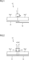
- FIG. 1 shows a linear motor based transport system LA according to the current state of the art.
- the linear motor-based transport system LA has a first segment Seg1 and a second segment Seg2, wherein the first segment Seg1 is arranged adjacent to the second segment Seg2.
- the first segment Seg1 has a first sensor S1 and the second segment Seg2 has a second sensor S2 associated therewith.
- On the segments Seg1, Seg2 a rotor L is moved, wherein the rotor L has a detection element E.
- the sensors S1, S2 of the segments Seg1, Seg2 are overlapping in the region of the transition to the first segment Seg1 to the second segment Seg2. In the region in which the rotor L passes from the first segment Seg1 to the second segment Seg2, the detection element E is registered by both sensors S1, S2.
- the rotor has a position x, wherein the position x corresponds to the position of the detection element E.
- a disadvantage of the arrangement shown here is the need for overlapping of the sensors S1, S2, which are assigned to the adjacent segments Seg1, Seg2.
- Another disadvantage of the prior art is the complicated detection of the position of the rotor in the transition region. The overlap is shown symbolically here.
- the respective sensors S1, S2 are alternately arranged on two different sides of the segments.
- FIG. 2 shows a linear motor based transport system LA.
- the linear motor based transport system LA has a first segment Seg1 and, adjacent thereto, a second segment Seg2.
- the first segment Seg1 has a first sensor S1 and the second segment Seg2 has a second sensor S2 associated therewith.
- the sensors of the first segment Seg1 and the second segment Seg2 do not overlap. It is possible that the sensors S1, S2 are arranged at a distance, ie that the first sensor S1 does not reach the end of the first segment Seg1 and the second sensor S2 does not start at the beginning of the second segment Seg2.
- the rotor L In order to determine the position x or the speed v of the rotor L, the rotor L has a first detection element E1 and a second detection element E2 up.
- the first detection element E1 is located at the position x1.
- the second detection element E2 is positioned at the position x2. Between the positions x1, x2 the distance corresponds to a difference D.
- the first detection element E1 is detected by the first sensor S1 and that the second detection element E2 is detected by the second sensor S2.
- the detection is indicated by the dashed arrows.
- the first detection element is detected by the first sensor S1 and the second detection element E2 is detected by the second sensor S2.
- overlapping of the sensors S1, S2 is no longer necessary.
- An assignment of the detection elements E1, E2 to the respective detecting sensors S1, S2 is indicated by dashed lines.
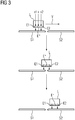
- FIG. 3 shows the transition of a rotor L.
- the transition of the rotor L takes place from the first segment Seg1 to the second segment Seg2.
- the position x and / or the speed v of the rotor L is detected by the first sensor S1.
- Both detection elements E1, E2 are detected by the first sensor S1.
- the second sensor S2 registers none of the detection elements E1, E2.
- a rotor L is shown whose detection elements E1, E2 are detected by one of the two sensors S1, S2. In this case, the first detection element E1 is detected by the first sensor S1 and the second detection element E2 by the second sensor S2.
- the position x and / or the speed v of the rotor L can be detected by a respective sensor S1 or S2 or by both sensors S1, S2.
- the position and / or the speed of the rotor L can be detected without interruption from the sensors S1, S2. If the rotor L moves on to the second segment Seg2, both detection elements E1, E2 are detected by the second sensor S2. This condition is in the lower part of the FIG. 3 shown.
- the rotor L is in each case assigned a virtual detection element E *.
- the virtual detection element E * corresponds to a detection element representing the position x of the rotor.
- the position of the virtual detection element E * can also be referred to as virtual position x *.
- FIG. 4 shows a linear motor based transport system LA.
- the linear motor-based transport system LA has analogous to FIG. 2 two adjacent segments Seg1, Seg2.
- a rotor L can be moved on the segments Seg1, Seg2, the rotor L having a first detection element E1 and a second detection element E2.
- the rotor L is shown in dashed lines, because the rotor L is not necessary for the function of the embodiment shown here.
- the segments Seg1, Seg2 are each assigned a first sensor S1 or a second sensor S2.
- the sensors S1, S2 are each connected to a drive control AS.
- the drive controller AS preferably has one or more power converters U1, U2.
- the respective power converter U1, U2 is used to power each segment Seg1, Seg2.
- the drive controller AS controls or regulates the energization of the segments Seg1, Seg2 with the aid of the converters U1, U2.
- the sensor evaluation unit SAE for the first sensor S1 and for the second sensor S1 is shown between the sensors S1, S2 and the detection unit. Alternatively, it is also possible to provide a first sensor evaluation unit SAE for the first sensor S1 and a second sensor evaluation unit SAE for the second sensor S2.
- the respective sensor evaluation unit SAE can also be assigned to the respective converter U.
- the sensor evaluation unit SAE calculates the position x of the virtual detection element E * from the position x1 of the first detection element E1 and / or the position x2 of the second detection element x2.
- the respective Sensor evaluation unit SAE can also be designed to evaluate a plurality (two, three four,%) Sensors S1, S2.
- a calculation of the position x of the virtual detection element E * is also possible by detecting the position of a detection element E1, E2.
- the position x1, x2 of the respective detection element E1, E2 is added or subtracted only half the difference D.
- the position x of the virtual detection element E * is transmitted as the position of the rotor L to the drive controller AS and / or to the power converters U1, U2.
- the position x of the virtual detection element E * is assigned the position of the respective runner L.
- the position x of the rotor L which is detected by the sensors S1, S2, serves as input for the control loop of the drive controller AS.
- the regulation of the position x and / or the speed v of the rotor L takes place in a converter U. This way, signal paths can be shortened.
- FIG. 5 shows a rotor L.
- the rotor L is preferably used for movement on a segment Seg1, Seg2.
- the rotor L has a first detection element E1 and, spaced apart in the direction of movement, a second detection element E2.
- the first detection element E1 may be different from the second detection element E2.
- the possible difference is symbolized by the different size of the detection elements E1, E2.
- the invention relates to a rotor L for a linear motor-based transport system LA, a method for operating such a linear motor based transport system LA and such a linear motor based transport system LA itself.
- the rotor L comprises a first detection element E1 and at least one second detection element E2, wherein the respective detection element E1, E2 is designed to detect the position of the rotor L, the first detection element E1 and the second detection element E2 spaced apart with the rotor L are connected and wherein the first detection element E1 of a first sensor S1 of the linear motor based transport system LA is detectable and / or the second detection element E2 is detected by a second sensor S2 of the linear motor based transport system LA.
- the use of such a rotor L in a linear motor-based transport system LA eliminates a hitherto necessary overlap of sensors S1, S2.
Landscapes
- Engineering & Computer Science (AREA)
- Power Engineering (AREA)
- Microelectronics & Electronic Packaging (AREA)
- Physics & Mathematics (AREA)
- Chemical & Material Sciences (AREA)
- Combustion & Propulsion (AREA)
- Electromagnetism (AREA)
- Linear Motors (AREA)
Priority Applications (1)
| Application Number | Priority Date | Filing Date | Title |
|---|---|---|---|
| EP16191738.0A EP3301797A1 (fr) | 2016-09-30 | 2016-09-30 | Läufer eines linearmotorbasiertes transportsystems, linearmo-torbasiertes transportsystem und verfahren |
Applications Claiming Priority (1)
| Application Number | Priority Date | Filing Date | Title |
|---|---|---|---|
| EP16191738.0A EP3301797A1 (fr) | 2016-09-30 | 2016-09-30 | Läufer eines linearmotorbasiertes transportsystems, linearmo-torbasiertes transportsystem und verfahren |
Publications (1)
| Publication Number | Publication Date |
|---|---|
| EP3301797A1 true EP3301797A1 (fr) | 2018-04-04 |
Family
ID=57199879
Family Applications (1)
| Application Number | Title | Priority Date | Filing Date |
|---|---|---|---|
| EP16191738.0A Withdrawn EP3301797A1 (fr) | 2016-09-30 | 2016-09-30 | Läufer eines linearmotorbasiertes transportsystems, linearmo-torbasiertes transportsystem und verfahren |
Country Status (1)
| Country | Link |
|---|---|
| EP (1) | EP3301797A1 (fr) |
Cited By (1)
| Publication number | Priority date | Publication date | Assignee | Title |
|---|---|---|---|---|
| EP4144675A1 (fr) * | 2021-09-03 | 2023-03-08 | Schneider Electric Industries SAS | Système de transport et procédé de détection des défauts dans un système de guidage d'un tel système de transport |
Citations (3)
| Publication number | Priority date | Publication date | Assignee | Title |
|---|---|---|---|---|
| US20080106155A1 (en) * | 2004-10-01 | 2008-05-08 | Kabushiki Kaisha Yaskawa Denki | Linear Motor System |
| DE102008008602A1 (de) | 2007-06-22 | 2008-12-24 | Siemens Aktiengesellschaft | Transfervorrichtung für Werkstückträger |
| DE102012204917A1 (de) * | 2012-03-27 | 2013-10-02 | Beckhoff Automation Gmbh | Positionserfassungsvorrichtung und Verfahren zum Erfassen einer Position eines beweglichen Elements einer Antriebsvorrichtung |
-
2016
- 2016-09-30 EP EP16191738.0A patent/EP3301797A1/fr not_active Withdrawn
Patent Citations (3)
| Publication number | Priority date | Publication date | Assignee | Title |
|---|---|---|---|---|
| US20080106155A1 (en) * | 2004-10-01 | 2008-05-08 | Kabushiki Kaisha Yaskawa Denki | Linear Motor System |
| DE102008008602A1 (de) | 2007-06-22 | 2008-12-24 | Siemens Aktiengesellschaft | Transfervorrichtung für Werkstückträger |
| DE102012204917A1 (de) * | 2012-03-27 | 2013-10-02 | Beckhoff Automation Gmbh | Positionserfassungsvorrichtung und Verfahren zum Erfassen einer Position eines beweglichen Elements einer Antriebsvorrichtung |
Cited By (1)
| Publication number | Priority date | Publication date | Assignee | Title |
|---|---|---|---|---|
| EP4144675A1 (fr) * | 2021-09-03 | 2023-03-08 | Schneider Electric Industries SAS | Système de transport et procédé de détection des défauts dans un système de guidage d'un tel système de transport |
Similar Documents
| Publication | Publication Date | Title |
|---|---|---|
| EP1826533B1 (fr) | Capteur magnétique | |
| DE102008008602B4 (de) | Transfervorrichtung für Werkstückträger sowie Verfahren zum Transportieren von Werkstückträgern | |
| EP3249803B1 (fr) | Commande de bobines de moteur linéaire à stator déployé d'un stator de moteur linéaire à stator déployé | |
| DE112010003456T5 (de) | Verteilte-anordnung-linearmotor und steuerungsverfahren eines verteilte-anordnung-linearmotors | |
| EP0452375B1 (fr) | Convoyeur automatique de marchandises a element de transport entraine par un moteur electrique lineaire | |
| DE102006046531A1 (de) | Drehgeber und Verfahren zu dessen Betrieb | |
| EP2115396B1 (fr) | Procédé et système a déterminer la position d'une pièce d'un moteur | |
| EP2460056B1 (fr) | Procédé et dispositif de surveillance de l'absence d'erreur d'une grandeur de déplacement sur un mécanisme d'entraînement électrique | |
| EP2105713A1 (fr) | Appareil de mesure de position et son procédé de fonctionnement | |
| DE102014223234B3 (de) | Verfahren und Vorrichtung zur Diagnose elektrischer Weichen | |
| EP2564166A2 (fr) | Système de détection incrémentiel de positions multiples pour un système de transfert électromagnétique en boucle fermée | |
| EP3235768B1 (fr) | Segment de stator pour un système de transport à moteur linéaire et système de transport | |
| EP3663722A1 (fr) | Procédé d'étalonnage automatique d'un capteur magnétique et capteur magnétique | |
| DE3133246C2 (de) | Elektrische Steuerungsvorrichtung für die anschlaglose Wegbegrenzung an Werkzeugmaschinen, insbesondere an Honmaschinen | |
| EP1470072B1 (fr) | Dispositif pour determiner la position d'une cabine d'ascenseur | |
| EP3188924B1 (fr) | Procédé et dispositif de surveillance d'un réseau électrique dans un véhicule ferroviaire et véhicule ferroviaire | |
| EP2474090B1 (fr) | Procédé et dispositif pour déterminer une position de rotor d'une machine synchrone | |
| WO2016001289A1 (fr) | Actionneur comprenant un capteur de position | |
| DE102005045374A1 (de) | Messvorrichtung mit einem Messkopf zur Positionsbestimmung eines Primärteils auf einem Sekundärteil und Verfahren zur Positionsbestimmung eines Primärteils auf einem Sekundärteil mit einem Messkopf | |
| DE102004019284A1 (de) | Vorrichtung zum Betrieb eines Synchronmotors | |
| DE10320759B4 (de) | Transportsystem mit Gebern zur Lageerfassung in einer bedruckstoffverarbeitenden Maschine | |
| DE10207549A1 (de) | Verfahren und Vorrichtung zum Betrieb eines Synchronmotors | |
| EP1853927B1 (fr) | Detecteur de mouvement equipé d'un circuit de surveillance d'un encodeur et procede correspondent de surveillance d'un encodeur | |
| EP2079086B1 (fr) | Unité de transformateur électrique | |
| DE29705615U1 (de) | Sensoranordnung |
Legal Events
| Date | Code | Title | Description |
|---|---|---|---|
| PUAI | Public reference made under article 153(3) epc to a published international application that has entered the european phase |
Free format text: ORIGINAL CODE: 0009012 |
|
| AK | Designated contracting states |
Kind code of ref document: A1 Designated state(s): AL AT BE BG CH CY CZ DE DK EE ES FI FR GB GR HR HU IE IS IT LI LT LU LV MC MK MT NL NO PL PT RO RS SE SI SK SM TR |
|
| AX | Request for extension of the european patent |
Extension state: BA ME |
|
| STAA | Information on the status of an ep patent application or granted ep patent |
Free format text: STATUS: THE APPLICATION IS DEEMED TO BE WITHDRAWN |
|
| 18D | Application deemed to be withdrawn |
Effective date: 20181005 |