EP3663722A1 - Procédé d'étalonnage automatique d'un capteur magnétique et capteur magnétique - Google Patents
Procédé d'étalonnage automatique d'un capteur magnétique et capteur magnétique Download PDFInfo
- Publication number
- EP3663722A1 EP3663722A1 EP18209910.1A EP18209910A EP3663722A1 EP 3663722 A1 EP3663722 A1 EP 3663722A1 EP 18209910 A EP18209910 A EP 18209910A EP 3663722 A1 EP3663722 A1 EP 3663722A1
- Authority
- EP
- European Patent Office
- Prior art keywords
- sensor
- magnet
- sensor element
- time
- sensor elements
- Prior art date
- Legal status (The legal status is an assumption and is not a legal conclusion. Google has not performed a legal analysis and makes no representation as to the accuracy of the status listed.)
- Granted
Links
Images
Classifications
-
- G—PHYSICS
- G01—MEASURING; TESTING
- G01D—MEASURING NOT SPECIALLY ADAPTED FOR A SPECIFIC VARIABLE; ARRANGEMENTS FOR MEASURING TWO OR MORE VARIABLES NOT COVERED IN A SINGLE OTHER SUBCLASS; TARIFF METERING APPARATUS; MEASURING OR TESTING NOT OTHERWISE PROVIDED FOR
- G01D5/00—Mechanical means for transferring the output of a sensing member; Means for converting the output of a sensing member to another variable where the form or nature of the sensing member does not constrain the means for converting; Transducers not specially adapted for a specific variable
- G01D5/12—Mechanical means for transferring the output of a sensing member; Means for converting the output of a sensing member to another variable where the form or nature of the sensing member does not constrain the means for converting; Transducers not specially adapted for a specific variable using electric or magnetic means
- G01D5/14—Mechanical means for transferring the output of a sensing member; Means for converting the output of a sensing member to another variable where the form or nature of the sensing member does not constrain the means for converting; Transducers not specially adapted for a specific variable using electric or magnetic means influencing the magnitude of a current or voltage
- G01D5/142—Mechanical means for transferring the output of a sensing member; Means for converting the output of a sensing member to another variable where the form or nature of the sensing member does not constrain the means for converting; Transducers not specially adapted for a specific variable using electric or magnetic means influencing the magnitude of a current or voltage using Hall-effect devices
- G01D5/145—Mechanical means for transferring the output of a sensing member; Means for converting the output of a sensing member to another variable where the form or nature of the sensing member does not constrain the means for converting; Transducers not specially adapted for a specific variable using electric or magnetic means influencing the magnitude of a current or voltage using Hall-effect devices influenced by the relative movement between the Hall device and magnetic fields
-
- G—PHYSICS
- G01—MEASURING; TESTING
- G01D—MEASURING NOT SPECIALLY ADAPTED FOR A SPECIFIC VARIABLE; ARRANGEMENTS FOR MEASURING TWO OR MORE VARIABLES NOT COVERED IN A SINGLE OTHER SUBCLASS; TARIFF METERING APPARATUS; MEASURING OR TESTING NOT OTHERWISE PROVIDED FOR
- G01D18/00—Testing or calibrating apparatus or arrangements provided for in groups G01D1/00 - G01D15/00
- G01D18/002—Automatic recalibration
- G01D18/006—Intermittent recalibration
-
- G—PHYSICS
- G01—MEASURING; TESTING
- G01D—MEASURING NOT SPECIALLY ADAPTED FOR A SPECIFIC VARIABLE; ARRANGEMENTS FOR MEASURING TWO OR MORE VARIABLES NOT COVERED IN A SINGLE OTHER SUBCLASS; TARIFF METERING APPARATUS; MEASURING OR TESTING NOT OTHERWISE PROVIDED FOR
- G01D18/00—Testing or calibrating apparatus or arrangements provided for in groups G01D1/00 - G01D15/00
- G01D18/008—Testing or calibrating apparatus or arrangements provided for in groups G01D1/00 - G01D15/00 with calibration coefficients stored in memory
Definitions
- the invention relates to a method for calibrating a magnetic sensor for determining a position of a transmitter magnet along a route according to the preamble of claim 1, and a magnetic sensor for performing the method.
- Magnetic sensors are often used on working cylinders in order to be able to detect the position of a reciprocating piston carrying a master magnet. In many applications, it is necessary to be able to continuously record the exact position of the piston or encoder magnet over a distance.
- a sensor is for example from the EP 2 166 313 A1 known and has a number of Hall sensor elements that detect a radial component of the magnetic field.
- a sensor element signal of such a Hall sensor element has a quasilinear area, which covers a partial area of the stroke path, so that the sensor magnetic position can be continuously detected in this partial area.
- the sensor element signals are calibrated to the position of the transmitter magnet with a calibration stroke of the piston.
- the calibration includes the determination of polynomial coefficients in order to adapt a polynomial to the quasilinear range. This adjustment depends on the shape of the magnetic field of the transmitter magnet, which in turn also depends on the cylinder geometry. Depending on the piston, the coefficients sometimes fit better or worse. This can lead to a high linearity error accordingly inaccurate piston position determination. Such causes of error for determining the piston position can be avoided or at least reduced by more suitable coefficients.
- a major advantage of the method according to the invention is that the time-consuming calibration for each individual cylinder is eliminated. Instead, the sensor can simply be installed in an application, i.e. on a cylinder, and the calibration is carried out with the first piston strokes. The cylinder geometry is irrelevant.
- each piston stroke can be used for calibration, provided that the piston movement in the area to be calibrated took place at a constant speed, but this is checked in the process. Overall, the calibration can be done automatically.
- the repetition of the calibration during the running time can be predetermined, that is to say take place at certain times or at certain time intervals (for example hours or days) or after a certain number of piston strokes, that is to say after a certain working time.
- the repetition rate is preferably adjustable.
- step f two time intervals T1 and T2 are compared in step f), the time intervals each being calculated from a time difference between two times tx, which are of the same size sensor element signals neighboring sensor elements belong. If the times are the same, then there is constant speed.
- the invention also relates to a magnetic sensor which is designed such that the method according to the invention can be carried out.
- the sensor has at least three identical sensor elements along the route, the sensor elements each being able to detect the magnetic field of the transmitter magnet at their location.
- the sensor has evaluation electronics, the sensor elements being arranged at an equidistant distance along the route and each sensor element detecting a component of the magnetic field and generating a sensor element signal dependent on the position of the transmitter magnet, and a memory for storing the sensor element signals.
- the evaluation electronics are designed to store time-signal-value pairs in a part of a sensor element signal that forms the respective measuring range during the movement of the transmitter magnet.
- a time signal value pair consists of a time tx at which the respective sensor element signal is detected and the associated sensor element signal.
- the evaluation electronics is further developed to determine whether the sensor magnet is moving past the sensor elements at a constant speed, and to determine the relative sensor magnet positions between two adjacent sensor elements from the times tx when a constant speed is present. Furthermore, the evaluation electronics are designed to approximate a polynomial from the time-signal-value pairs and the associated, determined magnetic encoder position to the measuring range of each sensor element signal by determining polynomial coefficients. Finally, the evaluation electronics are designed to output position values of the transmitter magnet in one working mode by means of the approximated polynomial via one of the sensor element signals.
- the sensor elements are preferably designed as Hall sensor elements and detect a radial component of the magnetic field.
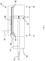
- the illustrated magnetic sensor 10 serves to determine the position C of a transmitter magnet 12 along a distance AB, the transmitter magnet 12 being mounted on a piston 14 of a working cylinder 16.
- a working cylinder 16 Such cylinders are used, for example, in automated machines such as robots and the like.
- the piston positions are detected by the sensor 10 when the piston moves in the piston direction 18.
- the sensor 10 has individual, at least three, sensor elements, which are preferably designed as Hall sensors 20 and are arranged equidistantly along the measuring section AB.
- the Hall sensors 20 are connected to evaluation electronics 30, which are preferably designed as microcontrollers. All necessary data and supply voltages are supplied to the sensor 10 according to the invention via a line 32 and position signals which are determined in the evaluation electronics 30 are output.
- the Hall sensors 20 and the evaluation electronics 30 are arranged on a printed circuit board 34.
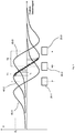
- Typical Hall signals that are output by Hall sensors 20 as a function of the path are shown in FIGS Fig. 2 shown with the signals of only three sensor elements 20 are shown.
- Each of these curves 40-1, 40-2 and 40-3 corresponds to a Hall signal U of a specific Hall sensor 20-1, 20-2 and 20-3, the signal curves shown corresponding schematically to a signal curve when the Hall Sensors detect the radial component of the magnetic field of the transmitter magnet 12, the north-south direction of which is in the piston direction 18.
- "Radial" thus means perpendicular to the piston direction 18.
- the method according to the invention for calibrating the magnetic sensor 10 is explained below.
- the process includes the following steps:
- the sensor elements 20 are arranged at an equidistant distance along the distance AB. In the exemplary embodiment shown, this was done in sensor 10 by the design of sensor 10 and the arrangement of sensor 10 on working cylinder 16.
- step c) during the piston stroke a component of the magnetic field, here the radial component, is detected by the sensor elements 20 and, depending on the position of the transmitter magnet 12, sensor element signals are provided by each sensor element.
- sensor element signals Hall signals
- 40-1, 40-2 and 40-3 each of the Hall elements 20-1, 20-2 or 20-3 are generated when the encoder magnet is moved past.
- the sensor element signals 40-1, 40-2 and 40-3 are stored.
- the signals only need to be stored in the measuring ranges, i.e. only in the quasilinear ranges.
- the storage takes place by recording time-signal value pairs in a step e) and storing them.
- a time signal value pair consists of a time tx and a sensor element signal Ux belonging to this time.
- the time-signal-value pairs are recorded and stored during the movement of the transmitter magnet 12. Only time-signal value pairs from the measuring ranges (quasi-linear ranges) of the sensor element signals 40-1, 40-2, and 40-3 are recorded and stored.
- a further step f) it is determined whether the transmitter magnet 12 is being moved past the sensor elements 20 at a constant speed. This is done by comparing two time intervals T1 and T2. Such a time interval is the time difference between two points in time that belong to sensor element signals of the same size from adjacent sensor elements. In the exemplary embodiment, these are the easy-to-determine points in time at which the signals have their zero crossing. If the time intervals T1 and T2 are the same, it is assumed that the piston has moved at a constant speed.
- step g) it is determined which transmitter magnet positions correspond to the times tx from the time signal value pairs. This can easily be determined from the distance between the sensor elements 20 and the number of measuring points between two sensor elements, that is to say the number of measuring points in a time interval T1 or T2.
- a polynomial is finally approximated in a step h) to the quasilinear part (measuring range) of a sensor element signal of each sensor element 20-1, 20-2, 20-3. This is done by determining polynomial coefficients from the time / signal value pairs and the respectively associated sensor magnet position determined after step g). That way A sensor magnetic position is assigned to each value of the sensor element signal U in the quasilinear section and the sensor 10 is calibrated.
- This calibration can be carried out automatically and continuously during ongoing operation, so that there is always a correct calibration regardless of changing environmental conditions (temperature, aging, etc.).
- the calibration can be started automatically with the first piston strokes during commissioning and can be carried out in parallel with the working mode.
Landscapes
- Physics & Mathematics (AREA)
- General Physics & Mathematics (AREA)
- Transmission And Conversion Of Sensor Element Output (AREA)
- Measurement Of Length, Angles, Or The Like Using Electric Or Magnetic Means (AREA)
Priority Applications (2)
| Application Number | Priority Date | Filing Date | Title |
|---|---|---|---|
| EP18209910.1A EP3663722B1 (fr) | 2018-12-03 | 2018-12-03 | Procédé d'étalonnage automatique d'un capteur magnétique et capteur magnétique |
| JP2019216492A JP6891254B2 (ja) | 2018-12-03 | 2019-11-29 | 磁気センサの自動較正方法及び磁気センサ |
Applications Claiming Priority (1)
| Application Number | Priority Date | Filing Date | Title |
|---|---|---|---|
| EP18209910.1A EP3663722B1 (fr) | 2018-12-03 | 2018-12-03 | Procédé d'étalonnage automatique d'un capteur magnétique et capteur magnétique |
Publications (2)
| Publication Number | Publication Date |
|---|---|
| EP3663722A1 true EP3663722A1 (fr) | 2020-06-10 |
| EP3663722B1 EP3663722B1 (fr) | 2021-05-26 |
Family
ID=64572244
Family Applications (1)
| Application Number | Title | Priority Date | Filing Date |
|---|---|---|---|
| EP18209910.1A Active EP3663722B1 (fr) | 2018-12-03 | 2018-12-03 | Procédé d'étalonnage automatique d'un capteur magnétique et capteur magnétique |
Country Status (2)
| Country | Link |
|---|---|
| EP (1) | EP3663722B1 (fr) |
| JP (1) | JP6891254B2 (fr) |
Cited By (4)
| Publication number | Priority date | Publication date | Assignee | Title |
|---|---|---|---|---|
| CN113866701A (zh) * | 2021-11-05 | 2021-12-31 | 北京鹏宇思睿科技有限公司 | 一种磁强计自动标定装置和方法 |
| CN115900528A (zh) * | 2021-08-03 | 2023-04-04 | 英飞凌科技股份有限公司 | 用于无全旋转安全测量的角度传感器校准方法 |
| EP4431878A1 (fr) * | 2023-03-14 | 2024-09-18 | KNORR-BREMSE Systeme für Nutzfahrzeuge GmbH | Agencement de capteurs |
| WO2024188533A1 (fr) * | 2023-03-14 | 2024-09-19 | Knorr-Bremse Systeme für Nutzfahrzeuge GmbH | Agencement de capteur |
Families Citing this family (2)
| Publication number | Priority date | Publication date | Assignee | Title |
|---|---|---|---|---|
| JP2024000613A (ja) | 2022-06-21 | 2024-01-09 | 旭化成エレクトロニクス株式会社 | 推定装置、推定方法、及びプログラム |
| JP2024005276A (ja) * | 2022-06-30 | 2024-01-17 | 旭化成エレクトロニクス株式会社 | 推定装置、推定装置を備える装置、推定方法、及びプログラム |
Citations (4)
| Publication number | Priority date | Publication date | Assignee | Title |
|---|---|---|---|---|
| EP1826533A1 (fr) * | 2006-02-22 | 2007-08-29 | Sick Ag | Capteur magnétique |
| WO2009078048A1 (fr) * | 2007-12-19 | 2009-06-25 | Roaldo Alberton | Procédé d'établissement de la position dynamique d'un actionneur de translation mécanique et codeur associé |
| EP2166313A1 (fr) | 2008-09-18 | 2010-03-24 | Sick Ag | Capteur magnétique |
| DE102013009862A1 (de) * | 2013-06-13 | 2014-12-18 | Festo Ag & Co. Kg | Sensoranordnung und Verfahren zum Betreiben einer Sensoranordnung |
Family Cites Families (6)
| Publication number | Priority date | Publication date | Assignee | Title |
|---|---|---|---|---|
| JPS5786459U (fr) * | 1981-06-11 | 1982-05-28 | ||
| JP2003269997A (ja) * | 2002-03-15 | 2003-09-25 | Tamagawa Seiki Co Ltd | 自己校正型角度検出器 |
| US8829893B2 (en) * | 2011-09-09 | 2014-09-09 | Honeywell International Inc. | Linear position sensor |
| US9372062B2 (en) * | 2012-05-04 | 2016-06-21 | Honeywell International Inc. | Techniques for calibrating a linear position sensor |
| JP6497591B2 (ja) * | 2015-12-16 | 2019-04-10 | Smc株式会社 | 位置検出装置 |
| JP6536478B2 (ja) * | 2016-05-17 | 2019-07-03 | 株式会社デンソー | 位置センサ |
-
2018
- 2018-12-03 EP EP18209910.1A patent/EP3663722B1/fr active Active
-
2019
- 2019-11-29 JP JP2019216492A patent/JP6891254B2/ja active Active
Patent Citations (4)
| Publication number | Priority date | Publication date | Assignee | Title |
|---|---|---|---|---|
| EP1826533A1 (fr) * | 2006-02-22 | 2007-08-29 | Sick Ag | Capteur magnétique |
| WO2009078048A1 (fr) * | 2007-12-19 | 2009-06-25 | Roaldo Alberton | Procédé d'établissement de la position dynamique d'un actionneur de translation mécanique et codeur associé |
| EP2166313A1 (fr) | 2008-09-18 | 2010-03-24 | Sick Ag | Capteur magnétique |
| DE102013009862A1 (de) * | 2013-06-13 | 2014-12-18 | Festo Ag & Co. Kg | Sensoranordnung und Verfahren zum Betreiben einer Sensoranordnung |
Cited By (5)
| Publication number | Priority date | Publication date | Assignee | Title |
|---|---|---|---|---|
| CN115900528A (zh) * | 2021-08-03 | 2023-04-04 | 英飞凌科技股份有限公司 | 用于无全旋转安全测量的角度传感器校准方法 |
| CN113866701A (zh) * | 2021-11-05 | 2021-12-31 | 北京鹏宇思睿科技有限公司 | 一种磁强计自动标定装置和方法 |
| EP4431878A1 (fr) * | 2023-03-14 | 2024-09-18 | KNORR-BREMSE Systeme für Nutzfahrzeuge GmbH | Agencement de capteurs |
| WO2024188533A1 (fr) * | 2023-03-14 | 2024-09-19 | Knorr-Bremse Systeme für Nutzfahrzeuge GmbH | Agencement de capteur |
| WO2024188541A1 (fr) * | 2023-03-14 | 2024-09-19 | Knorr-Bremse Systeme für Nutzfahrzeuge GmbH | Agencement de capteur |
Also Published As
| Publication number | Publication date |
|---|---|
| JP6891254B2 (ja) | 2021-06-18 |
| EP3663722B1 (fr) | 2021-05-26 |
| JP2020098203A (ja) | 2020-06-25 |
Similar Documents
| Publication | Publication Date | Title |
|---|---|---|
| EP3663722B1 (fr) | Procédé d'étalonnage automatique d'un capteur magnétique et capteur magnétique | |
| DE3144334C2 (de) | Wegmeßeinrichtung mit Referenzmarken | |
| EP0555507B1 (fr) | Capteur de position | |
| EP1195880B1 (fr) | Procédé pour augmenter la précision de positionnement d'un élément mobile par rapport à un stator | |
| DE3204012C1 (de) | Inkrementale Messeinrichtung | |
| EP2166312B2 (fr) | Capteur de trajectoire magnétique ou inductif | |
| EP3724609B1 (fr) | Dispositif de mesure linéaire pour déterminer une position absolue et guidage linéaire avec un tel dispositif de mesure | |
| EP1826533A1 (fr) | Capteur magnétique | |
| WO2012156139A1 (fr) | Dispositif et procédé de mesure de l'allongement d'une chaîne tournant en continu dans ledit dispositif | |
| DE3036830C2 (de) | Verfahren zur Korrektur von Meßwerten bei einem digitalen elektrischen Längen- oder Winkelmeßsystem | |
| EP1431707A1 (fr) | Procédé et dispositif pour l'acquisition, au moyen d'un capteur optoélectronique, d'objets placés sur un convoyeur | |
| DE102005047009A1 (de) | Absolutes Positionsmesssystem | |
| DE202008002844U1 (de) | Programmierbarer Positionssensor | |
| EP2116814B1 (fr) | Dispositif de mesure destiné à la détermination d'une position et/ou d'une vitesse | |
| DE102020113002B3 (de) | Bestimmen der Genauigkeit einer Bestückmaschine bei mehrfacher Verwendung eines Test-Bauelements | |
| DE102006011974A1 (de) | Verfahren zum Transportieren von Werkstückträgern in einer Montagelinie, Werkstückträger und Montageeinheit | |
| WO2020216827A1 (fr) | Dispositif de transport et procédé pour surveiller une position | |
| DE2713004A1 (de) | Lage-messwertgeber fuer werkzeugmaschinen und messvorrichtungen oder -maschinen | |
| EP4437305A1 (fr) | Procédé et dispositif de mesure d'une pièce en forme de plaque | |
| DE102020117885B4 (de) | Überwachung eines Rückzugsystems | |
| DE102016206905B4 (de) | Linearantriebssystem und Verfahren zur Ermittlung von zwei Positionen zweier Messelemente, die längs eines Bewegungswegs eines Linearantriebssystems bewegt werden | |
| EP2652445B1 (fr) | Tête de lecture | |
| DE4037545A1 (de) | Messeinrichtung | |
| DE102012213717A1 (de) | Inkrementalwegsensor | |
| EP1637486B1 (fr) | Procédé et dispositif de mesurer l'épaisseur des produits imprimés passant un dispositif de mesure dans un courant de transport en étant espacés à une distance déterminée |
Legal Events
| Date | Code | Title | Description |
|---|---|---|---|
| PUAI | Public reference made under article 153(3) epc to a published international application that has entered the european phase |
Free format text: ORIGINAL CODE: 0009012 |
|
| STAA | Information on the status of an ep patent application or granted ep patent |
Free format text: STATUS: THE APPLICATION HAS BEEN PUBLISHED |
|
| AK | Designated contracting states |
Kind code of ref document: A1 Designated state(s): AL AT BE BG CH CY CZ DE DK EE ES FI FR GB GR HR HU IE IS IT LI LT LU LV MC MK MT NL NO PL PT RO RS SE SI SK SM TR |
|
| AX | Request for extension of the european patent |
Extension state: BA ME |
|
| STAA | Information on the status of an ep patent application or granted ep patent |
Free format text: STATUS: REQUEST FOR EXAMINATION WAS MADE |
|
| 17P | Request for examination filed |
Effective date: 20201210 |
|
| RBV | Designated contracting states (corrected) |
Designated state(s): AL AT BE BG CH CY CZ DE DK EE ES FI FR GB GR HR HU IE IS IT LI LT LU LV MC MK MT NL NO PL PT RO RS SE SI SK SM TR |
|
| GRAP | Despatch of communication of intention to grant a patent |
Free format text: ORIGINAL CODE: EPIDOSNIGR1 |
|
| STAA | Information on the status of an ep patent application or granted ep patent |
Free format text: STATUS: GRANT OF PATENT IS INTENDED |
|
| INTG | Intention to grant announced |
Effective date: 20210311 |
|
| GRAS | Grant fee paid |
Free format text: ORIGINAL CODE: EPIDOSNIGR3 |
|
| GRAA | (expected) grant |
Free format text: ORIGINAL CODE: 0009210 |
|
| STAA | Information on the status of an ep patent application or granted ep patent |
Free format text: STATUS: THE PATENT HAS BEEN GRANTED |
|
| AK | Designated contracting states |
Kind code of ref document: B1 Designated state(s): AL AT BE BG CH CY CZ DE DK EE ES FI FR GB GR HR HU IE IS IT LI LT LU LV MC MK MT NL NO PL PT RO RS SE SI SK SM TR |
|
| REG | Reference to a national code |
Ref country code: GB Ref legal event code: FG4D Free format text: NOT ENGLISH |
|
| REG | Reference to a national code |
Ref country code: CH Ref legal event code: EP |
|
| REG | Reference to a national code |
Ref country code: AT Ref legal event code: REF Ref document number: 1396675 Country of ref document: AT Kind code of ref document: T Effective date: 20210615 |
|
| REG | Reference to a national code |
Ref country code: DE Ref legal event code: R096 Ref document number: 502018005417 Country of ref document: DE |
|
| REG | Reference to a national code |
Ref country code: IE Ref legal event code: FG4D Free format text: LANGUAGE OF EP DOCUMENT: GERMAN |
|
| REG | Reference to a national code |
Ref country code: LT Ref legal event code: MG9D |
|
| PG25 | Lapsed in a contracting state [announced via postgrant information from national office to epo] |
Ref country code: BG Free format text: LAPSE BECAUSE OF FAILURE TO SUBMIT A TRANSLATION OF THE DESCRIPTION OR TO PAY THE FEE WITHIN THE PRESCRIBED TIME-LIMIT Effective date: 20210826 Ref country code: FI Free format text: LAPSE BECAUSE OF FAILURE TO SUBMIT A TRANSLATION OF THE DESCRIPTION OR TO PAY THE FEE WITHIN THE PRESCRIBED TIME-LIMIT Effective date: 20210526 Ref country code: HR Free format text: LAPSE BECAUSE OF FAILURE TO SUBMIT A TRANSLATION OF THE DESCRIPTION OR TO PAY THE FEE WITHIN THE PRESCRIBED TIME-LIMIT Effective date: 20210526 Ref country code: LT Free format text: LAPSE BECAUSE OF FAILURE TO SUBMIT A TRANSLATION OF THE DESCRIPTION OR TO PAY THE FEE WITHIN THE PRESCRIBED TIME-LIMIT Effective date: 20210526 |
|
| REG | Reference to a national code |
Ref country code: NL Ref legal event code: MP Effective date: 20210526 |
|
| PG25 | Lapsed in a contracting state [announced via postgrant information from national office to epo] |
Ref country code: SE Free format text: LAPSE BECAUSE OF FAILURE TO SUBMIT A TRANSLATION OF THE DESCRIPTION OR TO PAY THE FEE WITHIN THE PRESCRIBED TIME-LIMIT Effective date: 20210526 Ref country code: RS Free format text: LAPSE BECAUSE OF FAILURE TO SUBMIT A TRANSLATION OF THE DESCRIPTION OR TO PAY THE FEE WITHIN THE PRESCRIBED TIME-LIMIT Effective date: 20210526 Ref country code: PL Free format text: LAPSE BECAUSE OF FAILURE TO SUBMIT A TRANSLATION OF THE DESCRIPTION OR TO PAY THE FEE WITHIN THE PRESCRIBED TIME-LIMIT Effective date: 20210526 Ref country code: NO Free format text: LAPSE BECAUSE OF FAILURE TO SUBMIT A TRANSLATION OF THE DESCRIPTION OR TO PAY THE FEE WITHIN THE PRESCRIBED TIME-LIMIT Effective date: 20210826 Ref country code: PT Free format text: LAPSE BECAUSE OF FAILURE TO SUBMIT A TRANSLATION OF THE DESCRIPTION OR TO PAY THE FEE WITHIN THE PRESCRIBED TIME-LIMIT Effective date: 20210927 Ref country code: LV Free format text: LAPSE BECAUSE OF FAILURE TO SUBMIT A TRANSLATION OF THE DESCRIPTION OR TO PAY THE FEE WITHIN THE PRESCRIBED TIME-LIMIT Effective date: 20210526 Ref country code: GR Free format text: LAPSE BECAUSE OF FAILURE TO SUBMIT A TRANSLATION OF THE DESCRIPTION OR TO PAY THE FEE WITHIN THE PRESCRIBED TIME-LIMIT Effective date: 20210827 Ref country code: IS Free format text: LAPSE BECAUSE OF FAILURE TO SUBMIT A TRANSLATION OF THE DESCRIPTION OR TO PAY THE FEE WITHIN THE PRESCRIBED TIME-LIMIT Effective date: 20210926 |
|
| PG25 | Lapsed in a contracting state [announced via postgrant information from national office to epo] |
Ref country code: NL Free format text: LAPSE BECAUSE OF FAILURE TO SUBMIT A TRANSLATION OF THE DESCRIPTION OR TO PAY THE FEE WITHIN THE PRESCRIBED TIME-LIMIT Effective date: 20210526 |
|
| PG25 | Lapsed in a contracting state [announced via postgrant information from national office to epo] |
Ref country code: SM Free format text: LAPSE BECAUSE OF FAILURE TO SUBMIT A TRANSLATION OF THE DESCRIPTION OR TO PAY THE FEE WITHIN THE PRESCRIBED TIME-LIMIT Effective date: 20210526 Ref country code: SK Free format text: LAPSE BECAUSE OF FAILURE TO SUBMIT A TRANSLATION OF THE DESCRIPTION OR TO PAY THE FEE WITHIN THE PRESCRIBED TIME-LIMIT Effective date: 20210526 Ref country code: EE Free format text: LAPSE BECAUSE OF FAILURE TO SUBMIT A TRANSLATION OF THE DESCRIPTION OR TO PAY THE FEE WITHIN THE PRESCRIBED TIME-LIMIT Effective date: 20210526 Ref country code: ES Free format text: LAPSE BECAUSE OF FAILURE TO SUBMIT A TRANSLATION OF THE DESCRIPTION OR TO PAY THE FEE WITHIN THE PRESCRIBED TIME-LIMIT Effective date: 20210526 Ref country code: DK Free format text: LAPSE BECAUSE OF FAILURE TO SUBMIT A TRANSLATION OF THE DESCRIPTION OR TO PAY THE FEE WITHIN THE PRESCRIBED TIME-LIMIT Effective date: 20210526 Ref country code: CZ Free format text: LAPSE BECAUSE OF FAILURE TO SUBMIT A TRANSLATION OF THE DESCRIPTION OR TO PAY THE FEE WITHIN THE PRESCRIBED TIME-LIMIT Effective date: 20210526 Ref country code: RO Free format text: LAPSE BECAUSE OF FAILURE TO SUBMIT A TRANSLATION OF THE DESCRIPTION OR TO PAY THE FEE WITHIN THE PRESCRIBED TIME-LIMIT Effective date: 20210526 |
|
| REG | Reference to a national code |
Ref country code: DE Ref legal event code: R097 Ref document number: 502018005417 Country of ref document: DE |
|
| PLBE | No opposition filed within time limit |
Free format text: ORIGINAL CODE: 0009261 |
|
| STAA | Information on the status of an ep patent application or granted ep patent |
Free format text: STATUS: NO OPPOSITION FILED WITHIN TIME LIMIT |
|
| 26N | No opposition filed |
Effective date: 20220301 |
|
| PG25 | Lapsed in a contracting state [announced via postgrant information from national office to epo] |
Ref country code: IS Free format text: LAPSE BECAUSE OF FAILURE TO SUBMIT A TRANSLATION OF THE DESCRIPTION OR TO PAY THE FEE WITHIN THE PRESCRIBED TIME-LIMIT Effective date: 20210926 Ref country code: AL Free format text: LAPSE BECAUSE OF FAILURE TO SUBMIT A TRANSLATION OF THE DESCRIPTION OR TO PAY THE FEE WITHIN THE PRESCRIBED TIME-LIMIT Effective date: 20210526 |
|
| PG25 | Lapsed in a contracting state [announced via postgrant information from national office to epo] |
Ref country code: MC Free format text: LAPSE BECAUSE OF FAILURE TO SUBMIT A TRANSLATION OF THE DESCRIPTION OR TO PAY THE FEE WITHIN THE PRESCRIBED TIME-LIMIT Effective date: 20210526 Ref country code: IT Free format text: LAPSE BECAUSE OF FAILURE TO SUBMIT A TRANSLATION OF THE DESCRIPTION OR TO PAY THE FEE WITHIN THE PRESCRIBED TIME-LIMIT Effective date: 20210526 |
|
| REG | Reference to a national code |
Ref country code: CH Ref legal event code: PL |
|
| REG | Reference to a national code |
Ref country code: BE Ref legal event code: MM Effective date: 20211231 |
|
| PG25 | Lapsed in a contracting state [announced via postgrant information from national office to epo] |
Ref country code: LU Free format text: LAPSE BECAUSE OF NON-PAYMENT OF DUE FEES Effective date: 20211203 Ref country code: IE Free format text: LAPSE BECAUSE OF NON-PAYMENT OF DUE FEES Effective date: 20211203 |
|
| PG25 | Lapsed in a contracting state [announced via postgrant information from national office to epo] |
Ref country code: FR Free format text: LAPSE BECAUSE OF NON-PAYMENT OF DUE FEES Effective date: 20211231 Ref country code: BE Free format text: LAPSE BECAUSE OF NON-PAYMENT OF DUE FEES Effective date: 20211231 |
|
| PG25 | Lapsed in a contracting state [announced via postgrant information from national office to epo] |
Ref country code: LI Free format text: LAPSE BECAUSE OF NON-PAYMENT OF DUE FEES Effective date: 20211231 Ref country code: CH Free format text: LAPSE BECAUSE OF NON-PAYMENT OF DUE FEES Effective date: 20211231 |
|
| PG25 | Lapsed in a contracting state [announced via postgrant information from national office to epo] |
Ref country code: CY Free format text: LAPSE BECAUSE OF FAILURE TO SUBMIT A TRANSLATION OF THE DESCRIPTION OR TO PAY THE FEE WITHIN THE PRESCRIBED TIME-LIMIT Effective date: 20210526 |
|
| PG25 | Lapsed in a contracting state [announced via postgrant information from national office to epo] |
Ref country code: HU Free format text: LAPSE BECAUSE OF FAILURE TO SUBMIT A TRANSLATION OF THE DESCRIPTION OR TO PAY THE FEE WITHIN THE PRESCRIBED TIME-LIMIT; INVALID AB INITIO Effective date: 20181203 |
|
| GBPC | Gb: european patent ceased through non-payment of renewal fee |
Effective date: 20221203 |
|
| PG25 | Lapsed in a contracting state [announced via postgrant information from national office to epo] |
Ref country code: GB Free format text: LAPSE BECAUSE OF NON-PAYMENT OF DUE FEES Effective date: 20221203 |
|
| PG25 | Lapsed in a contracting state [announced via postgrant information from national office to epo] |
Ref country code: MK Free format text: LAPSE BECAUSE OF FAILURE TO SUBMIT A TRANSLATION OF THE DESCRIPTION OR TO PAY THE FEE WITHIN THE PRESCRIBED TIME-LIMIT Effective date: 20210526 |
|
| PG25 | Lapsed in a contracting state [announced via postgrant information from national office to epo] |
Ref country code: MT Free format text: LAPSE BECAUSE OF FAILURE TO SUBMIT A TRANSLATION OF THE DESCRIPTION OR TO PAY THE FEE WITHIN THE PRESCRIBED TIME-LIMIT Effective date: 20210526 |
|
| REG | Reference to a national code |
Ref country code: AT Ref legal event code: MM01 Ref document number: 1396675 Country of ref document: AT Kind code of ref document: T Effective date: 20231203 |
|
| PG25 | Lapsed in a contracting state [announced via postgrant information from national office to epo] |
Ref country code: AT Free format text: LAPSE BECAUSE OF NON-PAYMENT OF DUE FEES Effective date: 20231203 |
|
| PG25 | Lapsed in a contracting state [announced via postgrant information from national office to epo] |
Ref country code: TR Free format text: LAPSE BECAUSE OF FAILURE TO SUBMIT A TRANSLATION OF THE DESCRIPTION OR TO PAY THE FEE WITHIN THE PRESCRIBED TIME-LIMIT Effective date: 20210526 |
|
| PGFP | Annual fee paid to national office [announced via postgrant information from national office to epo] |
Ref country code: DE Payment date: 20251222 Year of fee payment: 8 |
|
| PGFP | Annual fee paid to national office [announced via postgrant information from national office to epo] |
Ref country code: AT Payment date: 20260410 Year of fee payment: 5 |