EP3301821A1 - Antenne für eine nfc-vorrichtung sowie nfc-vorrichtung - Google Patents
Antenne für eine nfc-vorrichtung sowie nfc-vorrichtung Download PDFInfo
- Publication number
- EP3301821A1 EP3301821A1 EP16465542.5A EP16465542A EP3301821A1 EP 3301821 A1 EP3301821 A1 EP 3301821A1 EP 16465542 A EP16465542 A EP 16465542A EP 3301821 A1 EP3301821 A1 EP 3301821A1
- Authority
- EP
- European Patent Office
- Prior art keywords
- antenna
- loop
- wire
- area
- wire loop
- Prior art date
- Legal status (The legal status is an assumption and is not a legal conclusion. Google has not performed a legal analysis and makes no representation as to the accuracy of the status listed.)
- Granted
Links
Images


Classifications
-
- H—ELECTRICITY
- H04—ELECTRIC COMMUNICATION TECHNIQUE
- H04B—TRANSMISSION
- H04B5/00—Near-field transmission systems, e.g. inductive or capacitive transmission systems
- H04B5/20—Near-field transmission systems, e.g. inductive or capacitive transmission systems characterised by the transmission technique; characterised by the transmission medium
- H04B5/24—Inductive coupling
- H04B5/26—Inductive coupling using coils
-
- H—ELECTRICITY
- H04—ELECTRIC COMMUNICATION TECHNIQUE
- H04B—TRANSMISSION
- H04B5/00—Near-field transmission systems, e.g. inductive or capacitive transmission systems
- H04B5/20—Near-field transmission systems, e.g. inductive or capacitive transmission systems characterised by the transmission technique; characterised by the transmission medium
- H04B5/24—Inductive coupling
Definitions
- the invention is concerned with an antenna for an NFC device.
- the antenna comprises at least one wire loop.
- the invention also comprises an NFC device than can be used as an NFC reader or as an NFC receiver.
- An NFC reader may comprise an antenna with a wire loop that may be connected to an electronic circuit of the NFC reader.
- the wire loop functions as a reader antenna that may generate an antenna near field such that the wire loop is electro-magnetically coupled to another wire loop of the antenna of a second NFC device.
- the near field By coupling the wire loop of the NFC reader with the wire loop of the second NFC device the near field generates an electric voltage in the wire loop of the second NFC device according to the principle of the transformer.
- the carrier frequency of the field generated by the NFC reader may be in the range of 13.56 MHz plus/minus 7 kHz. This technology for NFC devices is standardized by, e.g., ISO 14443 and the NFC forum specifications.
- the wire loop of the reader device that is a first NFC device
- the wire loop of a second NFC device it must be made sure that the near field of the antenna of the first NFC device penetrates the loop area of wire loop of the second NFC device.
- the wire loop of an NFC antenna can be constituted by a single spiral loop.
- the antenna characteristics are specified by the number of turns, outline dimensions, copper or track thickness, width and spacing.
- the wire loop of an antenna of an NFC device is flat.
- the loop area that is defined or delimited by the wire loop is a flat or planar or plane area.
- the magnetic flux generated by one wire loop must penetrate the loop area of the other wire loop.
- the wire loops must be placed in parallel or co-planar to each other such that the flat loop area of one antenna lies on top of the flat loop area of the second antenna.
- an NFC device may be provided in the interior of the vehicle for coupling a second NFC device (e.g. a mobile phone) with the infotainment system of the motor vehicle.
- a second NFC device e.g. a mobile phone
- the invention provides an antenna for an NFC device.
- the antenna comprises at least one wire loop made of a wire, wherein each wire loop delimits a loop area such that an electric current and/or an electric voltage in the wire is coupled to a magnetic flux that penetrates the loop area.
- a magnetic near field may be provided, that is a magnetic field that is generated by the current flowing through the wire.
- an electric voltage is induced in the wire according to the law of induction.
- the magnetic field of the wire loop In order to couple such a magnetic field of the inventive antenna with a wire loop of a second antenna of another NFC device, the magnetic field of the wire loop must penetrate the loop area of the wire loop of the second antenna such that the second antenna may modulate the field according to NFC standards.
- the loop area of the inventive antenna is not flat or plane.
- the respective loop area of the at least one wire loop is bent or folded such that it encompasses a volume.
- the loop area may be shaped like the side of a geometric cylinder or like a tube.
- the invention provides the advantage that the magnetic field generated by the wire loop in case an electrical current is flowing through the wire is not simply directed or oriented perpendicular to a flat loop area. As the loop area of the wire loop is uneven or bent or folded, the field vectors of the magnetic field penetrating the loop area point into different directions. A wire loop of an antenna of another NFC device may thus be placed in the proximity of the inventive antenna in several different orientations and it will still be reliably penetrated by the magnetic field of the inventive antenna.
- the invention also comprises optional embodiments that provide features which afford additional technical advantages.
- the loop area is preferably bent or folded around an axis wherein the axis around which the loop area is bent or folded is oriented perpendicular to each normal vector of the loop area.
- the loop area of each wire loop is shaped like a cylinder or tube.
- the loop area is bent around an axis and encompasses the volume to more than 80%, preferably more than 90%. This allows for placing a wire loop of a second antenna inside the encompassed volume and the orientation of this second wire loop can be varied without losing a high degree of coupling with the inventive antenna.
- the effect of bending or folding the loop area is that different sections of the same wire of the wire loop form different sub-loops.
- the wire of the wire loop forms a respective further wire loops, i.e. the sub-loops, one at each end of the volume.
- the antenna characteristics of the bent loop area comprises at least two perpendicular coils.
- a preferred shape of the wire of the wire loop is the following: starting from a contact area for electrically contacting the wire loop, the wire forms a first half circle in a first plane and is then oriented perpendicular to the first plane towards a second plane that is arranged parallel or co-planar to the first plane. Following the wire further, the wire forms a full circle in the second plane and is then oriented back towards the first plane, where the wire forms a second half circle in the first plane to finally reach the contacting area. The first half circle in the first plane and the second half circle in the first plane together form a full circle. This shape may be repeated several times to obtain several windings of the wire loop.
- a "full circle” does not mean that the wire is short-circuited to form the full circle.
- a full circle of the wire is given, if the wire forms more than 70% of a circle and the remaining or missing part or the circle is used for direction an electric current into the circular loop and out of the circular loop.
- the antenna is designed as a storage container, wherein walls of the storage container delimit said volume and wherein the at least one wire loop is integrated into the storage walls.
- a storage container may be used to place a second NFC device inside the volume and hold it there.
- the storage container is designed as a cup holder or a coin holder or a door handle storage box or a glove box or a cradle for a portable mobile device or a general purpose storage box for a motor vehicle.
- This allows to hold the second NFC device, e.g. a mobile phone or smartphone, inside a motor vehicle.
- the antenna may be designed as a bracelet for a watch or a smart watch. This design can enhance the freedom of positioning the antenna when it is worn as a bracelet at an arm of a user.
- the bracelet may comprise a wristband and the wire loop may be integrated into the material of the wristband.
- the inventive NFC device By integrating the antenna into an NFC device, the inventive NFC device is obtained. Additionally, the inventive NFC device comprises a control circuit to transmit and/or receive communication data via the antenna on the basis of an NFC technology.
- the control circuit is designed to set up a communication channel for communicating with more than one other NFC device at the same time.
- the control circuit comprises a collision avoidance protocol such that two other NFC devices may be positioned or placed inside the volume and/or around the inventive antenna.
- two or more than two other NFC devices may communicate with the inventive NFC device, only one antenna with only one wire loop is needed or one antenna is sufficient, as the inventive antenna comprises multi-dimensional antenna characteristics that may couple with two different NFC device at the same time.
- the embodiment explaneed in the following is a preferred embodiment of the invention.
- the described components of the embodiment each represent individual features of the invention which are to be considered independently of each other and which each develop the invention also independently of each other and thereby are also to be regarded as a component of the invention in individual manner or in another than the shown combination.
- the described embodiment can also be supplemented by further features of the invention already described.
- Fig. 1 shows an NFC device 10 with an antenna 11 and a control circuit 12.
- the antenna 11 may be electrically connected to the control circuit 12.
- the control circuit 12 may comprise electronic components and/or a microcontroller and/or a microprocessor.
- the control circuit 12 may control an electric current 13 that may flow through a wire 14 of the antenna 11.
- the wire 14 is shaped or formed as a wire loop 15.
- the wire loop 15 is not flat.
- a loop area 16 that is delimited by the wire 14, is bent.
- the resulting shape of the loop area 16 is indicated by the hatching (///).
- the wire loop 15 may also be folded, that is the loop area 16 may comprise a kink or buckle.
- the loop area 16 is wrapped around or encompasses a three dimensional spatial segment or volume 17.
- the wire 14 starts at an electric contacting area 18 where the wire may be electrically connected to the control circuit 12. Starting from the contacting area 18 the wire forms a first half circle 19 in a first plane is then bent up towards a second plane where the wire 14 is shaped as a full circle 20 (apart from a gap). From the second plane the wire 14 then continues back to the first plane where wire 14 forms a second half circle 21 and thus reaches the contacting area 18 again.
- the first half circle 19 and the second half circle 21 form a second full circle (apart from two gaps) that is arranged co-planar to first full circle 20.
- the two full circles each constitute a separate wire loop, as in each full circle the electric current 13 flows unidirectional in a circle.
- the two full circles each constitute a sup-loop, i.e. a wire loop is provided at each end and of the volume 17.
- a magnetic field generated by these winding sub-loops is oriented perpendicular to a magnetic field generated by the entire wire loop 15 in the loop area 16. This results in antenna characteristics with perpendicular coils.
- Fig. 2 illustrates the difference between a flat or plane wire loop and the wire loop 15 of the antenna 11.
- the wire loop 15 is shown as a flat, conventional loop such that a normal vector or perpendicular vector 22 is identically oriented at each point of loop area 16.
- the loop area may be bent around an axis 23 that is perpendicular to normal vector 22.
- the bending direction 24 of the wire 14 is illustrated in Fig. 2 . This results in the shape shown in Fig. 1 .
- Fig. 3 illustrates how a conventional wire loop 25 of a second NFC device that may be placed next to the volume 17 and may thus be penetrated by magnetic field lines 26 generated by the current 13 in the wire loop 15.
- the wire loop 25 may be arranged outside the volume 17.
- the shape of the field lines 26 is mainly influenced by the top circle 20.
- the second NFC device may be part of a mobile device, like. e.g., a smartphone or a tablet PC.
- Fig. 4 illustrates, how a wire loop 25 of a second NFC device may be penetrated by field lines 26, if the wire loop 25 is arranged inside the volume 17.
- the shape of the field lines inside volume 17 may be mainly influenced by the shape of the loop area 16 that is the whole wire loop 15.
- the wire loop 25 may be rotated around the axis 23 and the coupling of the wire loop 25 with the wire loop 15 is above a pre-defined minimum value for all positions.
- Fig. 3 and Fig. 4 illustrates, how a wire loop 15 may comprise different spatial orientations and still a good coupling of the wire loop 15 and the wire loop 25 is possible for any relative orientation or position.
- the antenna 11 does not depend on placing the second wire loop 25 side-by-side in a co-planar manner to the wire loop 15 for ensuring a coupling between the two wire loops 15, 25. Instead, antenna 11 provides a wire loop 15 that ensures a multidimensional NFC operating volume. Due to the multidimensionality it is not necessary to place the second device with its wire loop 25 in a parallel, co-planar plane to the wire loop 15 of the NFC device 10 with antenna 11. The antenna 11 even provides multiple possible orientations for the second wire loop 25 (see Fig. 3 and Fig. 4 ).
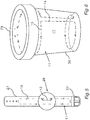
- Fig. 5 illustrates, how the antenna 11 may be designed as a bracelet 27 of a watch 28.
- Fig. 5 shows how the antenna 11 may be integrated into a bracelet 27 with a buckle 27'.
- Fig. 6 illustrates, how the antenna 11 may be designed as a storage container 29 that may be, e.g., a cup holder.
- the volume 17 may be delimited by walls 30 of the storage container 29 and the wire 14 of the wire loop 15 may be integrated in the wall 30.
- a second NFC device e.g. a mobile device
- the wire loop can be designed in a single loop or multiple wire loops.
- the antenna 11 can generate a magnetic field with field lines 26 that are oriented in multiple perpendicular directions with a field density that is similar for all directions. "Similar" can mean that at the surface of volume 17, the field density may vary less than 30%. Further, a wire loop 25 of another NFC device may also be placed inside the volume 17 that is enclosed by loop area 16.
Landscapes
- Engineering & Computer Science (AREA)
- Computer Networks & Wireless Communication (AREA)
- Signal Processing (AREA)
- Support Of Aerials (AREA)
- Details Of Aerials (AREA)
Priority Applications (1)
| Application Number | Priority Date | Filing Date | Title |
|---|---|---|---|
| EP16465542.5A EP3301821B1 (de) | 2016-09-29 | 2016-09-29 | Antenne für eine nfc-vorrichtung sowie nfc-vorrichtung |
Applications Claiming Priority (1)
| Application Number | Priority Date | Filing Date | Title |
|---|---|---|---|
| EP16465542.5A EP3301821B1 (de) | 2016-09-29 | 2016-09-29 | Antenne für eine nfc-vorrichtung sowie nfc-vorrichtung |
Publications (2)
| Publication Number | Publication Date |
|---|---|
| EP3301821A1 true EP3301821A1 (de) | 2018-04-04 |
| EP3301821B1 EP3301821B1 (de) | 2019-08-21 |
Family
ID=57226941
Family Applications (1)
| Application Number | Title | Priority Date | Filing Date |
|---|---|---|---|
| EP16465542.5A Active EP3301821B1 (de) | 2016-09-29 | 2016-09-29 | Antenne für eine nfc-vorrichtung sowie nfc-vorrichtung |
Country Status (1)
| Country | Link |
|---|---|
| EP (1) | EP3301821B1 (de) |
Cited By (2)
| Publication number | Priority date | Publication date | Assignee | Title |
|---|---|---|---|---|
| WO2020164499A1 (zh) * | 2019-02-12 | 2020-08-20 | 西交利物浦大学 | 一种应用于智能皮带系统的皮带天线 |
| CN114843778A (zh) * | 2022-05-31 | 2022-08-02 | 维沃移动通信有限公司 | 穿戴设备 |
Citations (6)
| Publication number | Priority date | Publication date | Assignee | Title |
|---|---|---|---|---|
| WO2004026025A1 (en) * | 2002-09-20 | 2004-04-01 | Shearwell Data Limited | Apparatus and method for the detection and identification of animals |
| EP2216914A2 (de) * | 2002-12-17 | 2010-08-11 | Sony Corporation | Kommunikationssystem, Kommunikationsverfahren und Datenverarbeitungsvorrichtung |
| JP2012151785A (ja) * | 2011-01-21 | 2012-08-09 | Tokai Rika Co Ltd | クレードル装置及び無線通信装置 |
| EP2858261A1 (de) * | 2013-01-29 | 2015-04-08 | Huawei Device Co., Ltd. | Nahfeldkommunikationsverfahren und -vorrichtung |
| US9189667B2 (en) * | 2011-12-27 | 2015-11-17 | The Gillette Company | Smart power source |
| WO2016132654A1 (ja) * | 2015-02-16 | 2016-08-25 | 株式会社村田製作所 | アンテナ装置および通信端末装置 |
-
2016
- 2016-09-29 EP EP16465542.5A patent/EP3301821B1/de active Active
Patent Citations (6)
| Publication number | Priority date | Publication date | Assignee | Title |
|---|---|---|---|---|
| WO2004026025A1 (en) * | 2002-09-20 | 2004-04-01 | Shearwell Data Limited | Apparatus and method for the detection and identification of animals |
| EP2216914A2 (de) * | 2002-12-17 | 2010-08-11 | Sony Corporation | Kommunikationssystem, Kommunikationsverfahren und Datenverarbeitungsvorrichtung |
| JP2012151785A (ja) * | 2011-01-21 | 2012-08-09 | Tokai Rika Co Ltd | クレードル装置及び無線通信装置 |
| US9189667B2 (en) * | 2011-12-27 | 2015-11-17 | The Gillette Company | Smart power source |
| EP2858261A1 (de) * | 2013-01-29 | 2015-04-08 | Huawei Device Co., Ltd. | Nahfeldkommunikationsverfahren und -vorrichtung |
| WO2016132654A1 (ja) * | 2015-02-16 | 2016-08-25 | 株式会社村田製作所 | アンテナ装置および通信端末装置 |
Cited By (2)
| Publication number | Priority date | Publication date | Assignee | Title |
|---|---|---|---|---|
| WO2020164499A1 (zh) * | 2019-02-12 | 2020-08-20 | 西交利物浦大学 | 一种应用于智能皮带系统的皮带天线 |
| CN114843778A (zh) * | 2022-05-31 | 2022-08-02 | 维沃移动通信有限公司 | 穿戴设备 |
Also Published As
| Publication number | Publication date |
|---|---|
| EP3301821B1 (de) | 2019-08-21 |
Similar Documents
| Publication | Publication Date | Title |
|---|---|---|
| US9985341B2 (en) | Device antenna for multiband communication | |
| US10511089B2 (en) | Antenna device and electronic apparatus | |
| US10256526B2 (en) | Near field communication antenna, near field communication device and mobile device having the same | |
| KR20170005670A (ko) | 무선 충전과 nfc 통신을 위한 무선 안테나 및 이를 적용한 무선 단말기 | |
| WO2014004282A1 (en) | Thin chassis near field communication (nfc) antenna integration | |
| KR102194806B1 (ko) | 무선 충전과 nfc 통신을 위한 무선 안테나 및 이를 적용한 무선 단말기 | |
| JPWO2015166834A1 (ja) | アンテナ装置および電子機器 | |
| PH12015501075B1 (en) | Non-stationary magnetic field emitter, its connection in system and data modulation method | |
| KR101843897B1 (ko) | 무선 충전과 nfc 통신을 위한 무선 안테나 및 이를 적용한 무선 단말기 | |
| US8730120B2 (en) | Transmission/reception antenna and transmission/reception device using same | |
| US20160149305A1 (en) | Antenna device and near field communication device including the same | |
| US11228085B2 (en) | Double loop antenna | |
| US20210367342A1 (en) | Optimized Near-Field Communication Antenna Structure for Reduced Coupling | |
| CN105075010B (zh) | 用于无线耦合的装置及方法 | |
| EP3301821B1 (de) | Antenne für eine nfc-vorrichtung sowie nfc-vorrichtung | |
| EP2933878B1 (de) | Antennenvorrichtung | |
| KR101922530B1 (ko) | 무선 충전과 nfc 통신을 위한 무선 안테나 및 이를 적용한 무선 단말기 | |
| KR101686789B1 (ko) | 휴대 단말기용 안테나 구조 | |
| KR102355538B1 (ko) | 자기 결합에 의한 통신을 위한 디바이스 | |
| US20130176094A1 (en) | Antenna assembly and communication device having same | |
| KR101671461B1 (ko) | 다중대역 칩 안테나, 이를 포함하는 배터리 팩 및 이를 포함하는 모바일 장치 | |
| JP7704533B2 (ja) | マルチバンド3dの汎用のアンテナ | |
| JP6549436B2 (ja) | アンテナ装置 | |
| KR101972053B1 (ko) | 무선 충전과 nfc 통신을 위한 무선 안테나 및 이를 적용한 무선 단말기 | |
| JP5508724B2 (ja) | アンテナ構造体、通信用機器、及び、アンテナ構造体の製造方法 |
Legal Events
| Date | Code | Title | Description |
|---|---|---|---|
| PUAI | Public reference made under article 153(3) epc to a published international application that has entered the european phase |
Free format text: ORIGINAL CODE: 0009012 |
|
| STAA | Information on the status of an ep patent application or granted ep patent |
Free format text: STATUS: THE APPLICATION HAS BEEN PUBLISHED |
|
| AK | Designated contracting states |
Kind code of ref document: A1 Designated state(s): AL AT BE BG CH CY CZ DE DK EE ES FI FR GB GR HR HU IE IS IT LI LT LU LV MC MK MT NL NO PL PT RO RS SE SI SK SM TR |
|
| AX | Request for extension of the european patent |
Extension state: BA ME |
|
| STAA | Information on the status of an ep patent application or granted ep patent |
Free format text: STATUS: REQUEST FOR EXAMINATION WAS MADE |
|
| 17P | Request for examination filed |
Effective date: 20181004 |
|
| RBV | Designated contracting states (corrected) |
Designated state(s): AL AT BE BG CH CY CZ DE DK EE ES FI FR GB GR HR HU IE IS IT LI LT LU LV MC MK MT NL NO PL PT RO RS SE SI SK SM TR |
|
| GRAP | Despatch of communication of intention to grant a patent |
Free format text: ORIGINAL CODE: EPIDOSNIGR1 |
|
| STAA | Information on the status of an ep patent application or granted ep patent |
Free format text: STATUS: GRANT OF PATENT IS INTENDED |
|
| INTG | Intention to grant announced |
Effective date: 20190322 |
|
| GRAS | Grant fee paid |
Free format text: ORIGINAL CODE: EPIDOSNIGR3 |
|
| GRAA | (expected) grant |
Free format text: ORIGINAL CODE: 0009210 |
|
| STAA | Information on the status of an ep patent application or granted ep patent |
Free format text: STATUS: THE PATENT HAS BEEN GRANTED |
|
| AK | Designated contracting states |
Kind code of ref document: B1 Designated state(s): AL AT BE BG CH CY CZ DE DK EE ES FI FR GB GR HR HU IE IS IT LI LT LU LV MC MK MT NL NO PL PT RO RS SE SI SK SM TR |
|
| REG | Reference to a national code |
Ref country code: GB Ref legal event code: FG4D |
|
| REG | Reference to a national code |
Ref country code: CH Ref legal event code: EP |
|
| REG | Reference to a national code |
Ref country code: DE Ref legal event code: R096 Ref document number: 602016018926 Country of ref document: DE |
|
| REG | Reference to a national code |
Ref country code: AT Ref legal event code: REF Ref document number: 1170912 Country of ref document: AT Kind code of ref document: T Effective date: 20190915 |
|
| REG | Reference to a national code |
Ref country code: IE Ref legal event code: FG4D |
|
| REG | Reference to a national code |
Ref country code: LT Ref legal event code: MG4D |
|
| REG | Reference to a national code |
Ref country code: NL Ref legal event code: MP Effective date: 20190821 |
|
| PG25 | Lapsed in a contracting state [announced via postgrant information from national office to epo] |
Ref country code: NL Free format text: LAPSE BECAUSE OF FAILURE TO SUBMIT A TRANSLATION OF THE DESCRIPTION OR TO PAY THE FEE WITHIN THE PRESCRIBED TIME-LIMIT Effective date: 20190821 Ref country code: HR Free format text: LAPSE BECAUSE OF FAILURE TO SUBMIT A TRANSLATION OF THE DESCRIPTION OR TO PAY THE FEE WITHIN THE PRESCRIBED TIME-LIMIT Effective date: 20190821 Ref country code: BG Free format text: LAPSE BECAUSE OF FAILURE TO SUBMIT A TRANSLATION OF THE DESCRIPTION OR TO PAY THE FEE WITHIN THE PRESCRIBED TIME-LIMIT Effective date: 20191121 Ref country code: SE Free format text: LAPSE BECAUSE OF FAILURE TO SUBMIT A TRANSLATION OF THE DESCRIPTION OR TO PAY THE FEE WITHIN THE PRESCRIBED TIME-LIMIT Effective date: 20190821 Ref country code: PT Free format text: LAPSE BECAUSE OF FAILURE TO SUBMIT A TRANSLATION OF THE DESCRIPTION OR TO PAY THE FEE WITHIN THE PRESCRIBED TIME-LIMIT Effective date: 20191223 Ref country code: LT Free format text: LAPSE BECAUSE OF FAILURE TO SUBMIT A TRANSLATION OF THE DESCRIPTION OR TO PAY THE FEE WITHIN THE PRESCRIBED TIME-LIMIT Effective date: 20190821 Ref country code: FI Free format text: LAPSE BECAUSE OF FAILURE TO SUBMIT A TRANSLATION OF THE DESCRIPTION OR TO PAY THE FEE WITHIN THE PRESCRIBED TIME-LIMIT Effective date: 20190821 Ref country code: NO Free format text: LAPSE BECAUSE OF FAILURE TO SUBMIT A TRANSLATION OF THE DESCRIPTION OR TO PAY THE FEE WITHIN THE PRESCRIBED TIME-LIMIT Effective date: 20191121 |
|
| PG25 | Lapsed in a contracting state [announced via postgrant information from national office to epo] |
Ref country code: RS Free format text: LAPSE BECAUSE OF FAILURE TO SUBMIT A TRANSLATION OF THE DESCRIPTION OR TO PAY THE FEE WITHIN THE PRESCRIBED TIME-LIMIT Effective date: 20190821 Ref country code: GR Free format text: LAPSE BECAUSE OF FAILURE TO SUBMIT A TRANSLATION OF THE DESCRIPTION OR TO PAY THE FEE WITHIN THE PRESCRIBED TIME-LIMIT Effective date: 20191122 Ref country code: IS Free format text: LAPSE BECAUSE OF FAILURE TO SUBMIT A TRANSLATION OF THE DESCRIPTION OR TO PAY THE FEE WITHIN THE PRESCRIBED TIME-LIMIT Effective date: 20191221 Ref country code: ES Free format text: LAPSE BECAUSE OF FAILURE TO SUBMIT A TRANSLATION OF THE DESCRIPTION OR TO PAY THE FEE WITHIN THE PRESCRIBED TIME-LIMIT Effective date: 20190821 Ref country code: LV Free format text: LAPSE BECAUSE OF FAILURE TO SUBMIT A TRANSLATION OF THE DESCRIPTION OR TO PAY THE FEE WITHIN THE PRESCRIBED TIME-LIMIT Effective date: 20190821 Ref country code: AL Free format text: LAPSE BECAUSE OF FAILURE TO SUBMIT A TRANSLATION OF THE DESCRIPTION OR TO PAY THE FEE WITHIN THE PRESCRIBED TIME-LIMIT Effective date: 20190821 |
|
| REG | Reference to a national code |
Ref country code: AT Ref legal event code: MK05 Ref document number: 1170912 Country of ref document: AT Kind code of ref document: T Effective date: 20190821 |
|
| PG25 | Lapsed in a contracting state [announced via postgrant information from national office to epo] |
Ref country code: TR Free format text: LAPSE BECAUSE OF FAILURE TO SUBMIT A TRANSLATION OF THE DESCRIPTION OR TO PAY THE FEE WITHIN THE PRESCRIBED TIME-LIMIT Effective date: 20190821 |
|
| PG25 | Lapsed in a contracting state [announced via postgrant information from national office to epo] |
Ref country code: DK Free format text: LAPSE BECAUSE OF FAILURE TO SUBMIT A TRANSLATION OF THE DESCRIPTION OR TO PAY THE FEE WITHIN THE PRESCRIBED TIME-LIMIT Effective date: 20190821 Ref country code: EE Free format text: LAPSE BECAUSE OF FAILURE TO SUBMIT A TRANSLATION OF THE DESCRIPTION OR TO PAY THE FEE WITHIN THE PRESCRIBED TIME-LIMIT Effective date: 20190821 Ref country code: AT Free format text: LAPSE BECAUSE OF FAILURE TO SUBMIT A TRANSLATION OF THE DESCRIPTION OR TO PAY THE FEE WITHIN THE PRESCRIBED TIME-LIMIT Effective date: 20190821 Ref country code: IT Free format text: LAPSE BECAUSE OF FAILURE TO SUBMIT A TRANSLATION OF THE DESCRIPTION OR TO PAY THE FEE WITHIN THE PRESCRIBED TIME-LIMIT Effective date: 20190821 Ref country code: RO Free format text: LAPSE BECAUSE OF FAILURE TO SUBMIT A TRANSLATION OF THE DESCRIPTION OR TO PAY THE FEE WITHIN THE PRESCRIBED TIME-LIMIT Effective date: 20190821 Ref country code: PL Free format text: LAPSE BECAUSE OF FAILURE TO SUBMIT A TRANSLATION OF THE DESCRIPTION OR TO PAY THE FEE WITHIN THE PRESCRIBED TIME-LIMIT Effective date: 20190821 |
|
| PG25 | Lapsed in a contracting state [announced via postgrant information from national office to epo] |
Ref country code: SM Free format text: LAPSE BECAUSE OF FAILURE TO SUBMIT A TRANSLATION OF THE DESCRIPTION OR TO PAY THE FEE WITHIN THE PRESCRIBED TIME-LIMIT Effective date: 20190821 Ref country code: MC Free format text: LAPSE BECAUSE OF FAILURE TO SUBMIT A TRANSLATION OF THE DESCRIPTION OR TO PAY THE FEE WITHIN THE PRESCRIBED TIME-LIMIT Effective date: 20190821 Ref country code: IS Free format text: LAPSE BECAUSE OF FAILURE TO SUBMIT A TRANSLATION OF THE DESCRIPTION OR TO PAY THE FEE WITHIN THE PRESCRIBED TIME-LIMIT Effective date: 20200224 Ref country code: SK Free format text: LAPSE BECAUSE OF FAILURE TO SUBMIT A TRANSLATION OF THE DESCRIPTION OR TO PAY THE FEE WITHIN THE PRESCRIBED TIME-LIMIT Effective date: 20190821 Ref country code: CZ Free format text: LAPSE BECAUSE OF FAILURE TO SUBMIT A TRANSLATION OF THE DESCRIPTION OR TO PAY THE FEE WITHIN THE PRESCRIBED TIME-LIMIT Effective date: 20190821 |
|
| REG | Reference to a national code |
Ref country code: CH Ref legal event code: PL |
|
| REG | Reference to a national code |
Ref country code: DE Ref legal event code: R097 Ref document number: 602016018926 Country of ref document: DE |
|
| PLBE | No opposition filed within time limit |
Free format text: ORIGINAL CODE: 0009261 |
|
| STAA | Information on the status of an ep patent application or granted ep patent |
Free format text: STATUS: NO OPPOSITION FILED WITHIN TIME LIMIT |
|
| PG2D | Information on lapse in contracting state deleted |
Ref country code: IS |
|
| PG25 | Lapsed in a contracting state [announced via postgrant information from national office to epo] |
Ref country code: LI Free format text: LAPSE BECAUSE OF NON-PAYMENT OF DUE FEES Effective date: 20190930 Ref country code: IE Free format text: LAPSE BECAUSE OF NON-PAYMENT OF DUE FEES Effective date: 20190929 Ref country code: LU Free format text: LAPSE BECAUSE OF NON-PAYMENT OF DUE FEES Effective date: 20190929 Ref country code: CH Free format text: LAPSE BECAUSE OF NON-PAYMENT OF DUE FEES Effective date: 20190930 |
|
| 26N | No opposition filed |
Effective date: 20200603 |
|
| REG | Reference to a national code |
Ref country code: BE Ref legal event code: MM Effective date: 20190930 |
|
| PG25 | Lapsed in a contracting state [announced via postgrant information from national office to epo] |
Ref country code: BE Free format text: LAPSE BECAUSE OF NON-PAYMENT OF DUE FEES Effective date: 20190930 Ref country code: SI Free format text: LAPSE BECAUSE OF FAILURE TO SUBMIT A TRANSLATION OF THE DESCRIPTION OR TO PAY THE FEE WITHIN THE PRESCRIBED TIME-LIMIT Effective date: 20190821 |
|
| PG25 | Lapsed in a contracting state [announced via postgrant information from national office to epo] |
Ref country code: CY Free format text: LAPSE BECAUSE OF FAILURE TO SUBMIT A TRANSLATION OF THE DESCRIPTION OR TO PAY THE FEE WITHIN THE PRESCRIBED TIME-LIMIT Effective date: 20190821 |
|
| PG25 | Lapsed in a contracting state [announced via postgrant information from national office to epo] |
Ref country code: HU Free format text: LAPSE BECAUSE OF FAILURE TO SUBMIT A TRANSLATION OF THE DESCRIPTION OR TO PAY THE FEE WITHIN THE PRESCRIBED TIME-LIMIT; INVALID AB INITIO Effective date: 20160929 Ref country code: MT Free format text: LAPSE BECAUSE OF FAILURE TO SUBMIT A TRANSLATION OF THE DESCRIPTION OR TO PAY THE FEE WITHIN THE PRESCRIBED TIME-LIMIT Effective date: 20190821 |
|
| PG25 | Lapsed in a contracting state [announced via postgrant information from national office to epo] |
Ref country code: MK Free format text: LAPSE BECAUSE OF FAILURE TO SUBMIT A TRANSLATION OF THE DESCRIPTION OR TO PAY THE FEE WITHIN THE PRESCRIBED TIME-LIMIT Effective date: 20190821 |
|
| REG | Reference to a national code |
Ref country code: DE Ref legal event code: R081 Ref document number: 602016018926 Country of ref document: DE Owner name: CONTINENTAL AUTOMOTIVE TECHNOLOGIES GMBH, DE Free format text: FORMER OWNER: CONTINENTAL AUTOMOTIVE GMBH, 30165 HANNOVER, DE Ref country code: DE Ref legal event code: R081 Ref document number: 602016018926 Country of ref document: DE Owner name: AUMOVIO GERMANY GMBH, DE Free format text: FORMER OWNER: CONTINENTAL AUTOMOTIVE GMBH, 30165 HANNOVER, DE |
|
| REG | Reference to a national code |
Ref country code: GB Ref legal event code: 732E Free format text: REGISTERED BETWEEN 20230223 AND 20230301 |
|
| P01 | Opt-out of the competence of the unified patent court (upc) registered |
Effective date: 20230522 |
|
| REG | Reference to a national code |
Ref country code: DE Ref legal event code: R081 Ref document number: 602016018926 Country of ref document: DE Owner name: CONTINENTAL AUTOMOTIVE TECHNOLOGIES GMBH, DE Free format text: FORMER OWNER: CONTINENTAL AUTOMOTIVE TECHNOLOGIES GMBH, 30165 HANNOVER, DE Ref country code: DE Ref legal event code: R081 Ref document number: 602016018926 Country of ref document: DE Owner name: AUMOVIO GERMANY GMBH, DE Free format text: FORMER OWNER: CONTINENTAL AUTOMOTIVE TECHNOLOGIES GMBH, 30165 HANNOVER, DE |
|
| PGFP | Annual fee paid to national office [announced via postgrant information from national office to epo] |
Ref country code: DE Payment date: 20250930 Year of fee payment: 10 |
|
| PGFP | Annual fee paid to national office [announced via postgrant information from national office to epo] |
Ref country code: GB Payment date: 20250919 Year of fee payment: 10 |
|
| PGFP | Annual fee paid to national office [announced via postgrant information from national office to epo] |
Ref country code: FR Payment date: 20250922 Year of fee payment: 10 |
|
| REG | Reference to a national code |
Ref country code: DE Ref legal event code: R081 Ref document number: 602016018926 Country of ref document: DE Owner name: AUMOVIO GERMANY GMBH, DE Free format text: FORMER OWNER: CONTINENTAL AUTOMOTIVE TECHNOLOGIES GMBH, 30175 HANNOVER, DE |