EP3301824B1 - Composant de réseau de communication et procédé de demande d'informations de canal - Google Patents
Composant de réseau de communication et procédé de demande d'informations de canal Download PDFInfo
- Publication number
- EP3301824B1 EP3301824B1 EP16191100.3A EP16191100A EP3301824B1 EP 3301824 B1 EP3301824 B1 EP 3301824B1 EP 16191100 A EP16191100 A EP 16191100A EP 3301824 B1 EP3301824 B1 EP 3301824B1
- Authority
- EP
- European Patent Office
- Prior art keywords
- network component
- communication network
- mobile communication
- output
- communication terminals
- Prior art date
- Legal status (The legal status is an assumption and is not a legal conclusion. Google has not performed a legal analysis and makes no representation as to the accuracy of the status listed.)
- Active
Links
- 238000004891 communication Methods 0.000 title claims description 90
- 238000000034 method Methods 0.000 title claims description 18
- 238000010295 mobile communication Methods 0.000 claims description 56
- 230000011664 signaling Effects 0.000 claims description 7
- 230000001413 cellular effect Effects 0.000 claims description 3
- 230000037230 mobility Effects 0.000 claims 1
- 230000005540 biological transmission Effects 0.000 description 15
- 238000012797 qualification Methods 0.000 description 13
- 239000011159 matrix material Substances 0.000 description 8
- 239000013598 vector Substances 0.000 description 7
- 238000013459 approach Methods 0.000 description 6
- 230000002123 temporal effect Effects 0.000 description 6
- 241000053227 Themus Species 0.000 description 4
- 230000000875 corresponding effect Effects 0.000 description 4
- 238000010586 diagram Methods 0.000 description 4
- 230000003044 adaptive effect Effects 0.000 description 3
- 238000004422 calculation algorithm Methods 0.000 description 3
- 230000008859 change Effects 0.000 description 3
- 230000007774 longterm Effects 0.000 description 3
- 230000009897 systematic effect Effects 0.000 description 3
- 230000008901 benefit Effects 0.000 description 2
- 230000010267 cellular communication Effects 0.000 description 2
- 230000001276 controlling effect Effects 0.000 description 2
- 238000005516 engineering process Methods 0.000 description 2
- 230000007246 mechanism Effects 0.000 description 2
- 230000008520 organization Effects 0.000 description 2
- 230000009467 reduction Effects 0.000 description 2
- 238000007630 basic procedure Methods 0.000 description 1
- 230000009286 beneficial effect Effects 0.000 description 1
- 238000004590 computer program Methods 0.000 description 1
- 230000002596 correlated effect Effects 0.000 description 1
- 230000003247 decreasing effect Effects 0.000 description 1
- 230000001419 dependent effect Effects 0.000 description 1
- 230000000763 evoking effect Effects 0.000 description 1
- 230000006870 function Effects 0.000 description 1
- 238000011835 investigation Methods 0.000 description 1
- 238000012545 processing Methods 0.000 description 1
- 239000000523 sample Substances 0.000 description 1
- 230000035945 sensitivity Effects 0.000 description 1
- 238000010206 sensitivity analysis Methods 0.000 description 1
- 238000004088 simulation Methods 0.000 description 1
- 238000001228 spectrum Methods 0.000 description 1
- 230000003068 static effect Effects 0.000 description 1
- 238000012360 testing method Methods 0.000 description 1
Images


Classifications
-
- H—ELECTRICITY
- H04—ELECTRIC COMMUNICATION TECHNIQUE
- H04B—TRANSMISSION
- H04B7/00—Radio transmission systems, i.e. using radiation field
- H04B7/02—Diversity systems; Multi-antenna system, i.e. transmission or reception using multiple antennas
- H04B7/04—Diversity systems; Multi-antenna system, i.e. transmission or reception using multiple antennas using two or more spaced independent antennas
- H04B7/0413—MIMO systems
- H04B7/0456—Selection of precoding matrices or codebooks, e.g. using matrices antenna weighting
-
- H—ELECTRICITY
- H04—ELECTRIC COMMUNICATION TECHNIQUE
- H04B—TRANSMISSION
- H04B7/00—Radio transmission systems, i.e. using radiation field
- H04B7/02—Diversity systems; Multi-antenna system, i.e. transmission or reception using multiple antennas
- H04B7/04—Diversity systems; Multi-antenna system, i.e. transmission or reception using multiple antennas using two or more spaced independent antennas
- H04B7/0413—MIMO systems
- H04B7/0452—Multi-user MIMO systems
-
- H—ELECTRICITY
- H04—ELECTRIC COMMUNICATION TECHNIQUE
- H04B—TRANSMISSION
- H04B7/00—Radio transmission systems, i.e. using radiation field
- H04B7/02—Diversity systems; Multi-antenna system, i.e. transmission or reception using multiple antennas
- H04B7/04—Diversity systems; Multi-antenna system, i.e. transmission or reception using multiple antennas using two or more spaced independent antennas
- H04B7/06—Diversity systems; Multi-antenna system, i.e. transmission or reception using multiple antennas using two or more spaced independent antennas at the transmitting station
- H04B7/0613—Diversity systems; Multi-antenna system, i.e. transmission or reception using multiple antennas using two or more spaced independent antennas at the transmitting station using simultaneous transmission
- H04B7/0615—Diversity systems; Multi-antenna system, i.e. transmission or reception using multiple antennas using two or more spaced independent antennas at the transmitting station using simultaneous transmission of weighted versions of same signal
- H04B7/0619—Diversity systems; Multi-antenna system, i.e. transmission or reception using multiple antennas using two or more spaced independent antennas at the transmitting station using simultaneous transmission of weighted versions of same signal using feedback from receiving side
- H04B7/0636—Feedback format
- H04B7/0645—Variable feedback
Definitions
- Embodiments described herein generally relate to communication network components and methods for requesting channel information.
- Advanced communication techniques such as multiple-input multiple-output and in particular multi-user MIMO (MU-MIMO) for communication between the network side of a cellular communication system and a subscriber terminal require the feedback of channel information with high accuracy from the subscriber terminal to the network side. This introduces a high feedback overhead as well as high computational complexity on the terminal side. Accordingly, approaches to provide channel information feedback efficiently are desirable.
- MU-MIMO multi-user MIMO
- US 2009/0086842 A1 relates to wireless communication systems that allow both single-user MIMO subscriber stations and multi-user MIMO subscriber stations to operate within a common network region.
- a base station communicates with a single subscriber station at a time, through a corresponding MIMO channel.
- the base station may first transmit channel sounding to the subscriber station through the channel.
- the subscriber station uses the channel sounding to generate a channel matrix and beam forming information (e.g., one or more beam forming vectors).
- the beam forming information may then be fed back to the base station for use in performing pre-coding in a subsequent data transmission.
- MU-MIMO a base station may communicate with multiple subscriber stations at the same time and within the same frequency band.
- the base station may collect channel related information from a large number of subscriber stations in a corresponding cell and then analyze the information to select a smaller number of subscriber stations for simultaneous communication. The base station may then use the channel related information to perform pre-coding to simultaneously transmit to the selected subscriber stations.
- the channel related information may be obtained from the subscriber stations in a manner similar to that described for SU-MIMO. That is, the base station can first transmit channel sounding to the subscriber stations in the cell and the subscriber stations can then use the received channel sounding to generate beam forming vectors. The beam forming vectors may then be fed back to the base station from the individual subscriber stations at appropriate times.
- a multi-resolution codebook is provided that can service both SU-MIMO subscriber stations and MU-MIMO subscriber stations in the same cell.
- the multi-resolution codebook may include a higher resolution "fine" codebook for use with MU-MIMO subscriber stations and a lower resolution "coarse" codebook for use with SU-MIMO subscriber stations. That is, the MU-MIMO subscriber stations within the cell will use the fine codebook to quantize channel related information (e.g., beam forming vectors, etc.) to be fed back to the base station and the SU-MIMO subscriber stations within the cell will use the coarse codebook to quantize channel related information to be fed back to the base station.
- channel related information e.g., beam forming vectors, etc.
- a document TSG-RAN WG1 #59bis presented by ZTE in Valencia, Spain, January 18-22, 2010 and entitled "Variable Granularity Feedback” proposes to divide a cell, in which MU-MIMO is used, into several feedback rate regions and to employ codebooks with different granularity for each region, based on their average SNR.
- US 2008/0165876 A1 relates to the generation of a codebook for a MIMO system.
- a generated codebook can be downloaded from a base station to a terminal.
- EP 1919096 A1 relates to a MIMO system in which differential precoding information is provided for tracking small changes in the radio channel.
- the codebook is not able to track faster changes in the radio channel as for example evoked by high mobility.
- a detector may decide on transmitting absolute precoding information.
- the present disclosure provides a scheme that reduces overhead.
- Figure 1 shows a communication system 100, e.g. an LTE (Long Term Evolution) communication system.
- LTE Long Term Evolution
- the communication system 100 includes a radio access network (e.g. an E-UTRAN, Evolved UMTS (Universal Mobile Communications System) Terrestrial Radio Access Network according to LTE) 101 and a core network (e.g. an EPC, Evolved Packet Core, according LTE) 102.
- the radio access network 101 may include base (transceiver) stations (e.g. eNodeBs, eNBs, according to LTE) 103. Each base station 103 provides radio coverage for one or more mobile radio cells 104 of the radio access network 101.
- a mobile terminal (also referred to as UE, user equipment, or MS, mobile station) 105 located in one of the mobile radio cells 104 (in this example the leftmost radio cell 104) may communicate with the core network 102 and with other mobile terminals 105 via the base station providing coverage in (in other words operating) the mobile radio cell.
- UE user equipment
- MS mobile station
- Control and user data are transmitted between a base station 103 and a mobile terminal 105 located in the mobile radio cell 104 operated by the base station 103 over the air interface 106 on the basis of a multiple access method.
- the base stations 103 are interconnected with each other by means of a first interface 107, e.g. an X2 interface.
- the base stations 103 are also connected by means of a second interface 108, e.g. an S1 interface, to the core network, e.g. to an MME (Mobility Management Entity) 109, and a Serving Gateway (S-GW) 110.
- MME Mobility Management Entity
- S-GW Serving Gateway
- the MME 109 is responsible for controlling the mobility of mobile terminals located in the coverage area of E-UTRAN
- the S-GW 110 is responsible for handling the transmission of user data between mobile terminals 105 and core network 102.
- the radio access network 101 and the core network may support communication according to various communication technologies, e.g. mobile communication standards.
- each base station 103 may provide a radio communication connection via the air interface between itself and the mobile terminal 105 according to LTE, UMTS, GSM (Global System for Mobile Communications), GPRS (General Packet Radio Service), EDGE (Enhanced Data Rates for GSM Evolution) radio access.
- the radio access network 102 may operate as an E-UTRAN, a UTRAN, a GSM radio access network, or a GERAN (GSM EDGE Radio Access Network).
- the core network 102 may include the functionality of an EPC, a UMTS core network or a GSM core network.
- the approaches described herein may also be applied to future RAT technologies such as 5G.
- the mobile terminal 105 For uplink radio communication via the air interface 106, the mobile terminal 105 includes a radio transmitter (TX RF) 111.
- TX RF radio transmitter
- the mobile terminal 105 may include an identity module 112 (e.g. implemented by a chip card) that allows the mobile terminal 105 to identify itself as a subscriber of the communication network (e.g. as an LTE subscriber) formed by the radio access network 101 and the core network 102 and thus to use the communication network as a home network.
- an identity module 112 e.g. implemented by a chip card
- the mobile terminal 105 as well as its serving base station 103 may each be provided with a plurality of antennas and the base station 103 may serve the mobile terminal 105 using MIMO (multiple-input multiple-output). This is illustrated in figure 2 .
- MIMO multiple-input multiple-output
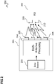
- Figure 2 shows a communication arrangement 200 according to an embodiment.
- the communication arrangement 200 includes a transmitter (TX) 201, e.g. corresponding to a base station 103, and a receiver (RX) 202, e.g. corresponding to the mobile terminal 105 which is served by the base station 103.
- the transmitter 201 includes a data source 203 which generates data to be transmitted in the form of data symbols (e.g. modulation symbols selected from a set of constellation symbols).
- the data symbols are supplied to a precoding circuit 204 which generates transmission symbols from the data symbols and associates each transmission symbol with one of a plurality of antennas 205, 206, 207, 208 and a transmission resource.
- Each transmission symbol is transmitted to the receiver 202, which may include a plurality of receiving antennas 209, 210 (for example two or more receiving antennas) using the antenna 205, 206, 207, 208 and the transmission resource associated with the transmission symbol.
- the transmitter includes four transmit antennas.
- the transmission resource is for example a time slot (e.g. a time transmission interval) or a (sub-)carrier signal. That means that a transmission symbol is for example associated with a time slot and is sent in this time slot or is associated with a carrier signal and is transmitted using this carrier signal (or both).
- figure 2 can be seen as a SU(single user)-MIMO scenario, where a single multi-antenna transmitter is communicating with a single multi-antenna receiver.
- a multi-antenna transmitter communicates with a plurality of different receivers (e.g. communication terminals) using the same frequency spectrum.
- the high accuracy of the feedback can be achieved by introducing a high granularity (i.e. resolution) codebook which, however, entails high feedback overhead as well as high computational complexity at the MS.
- the current 3GPP LTE standard does not include usage of the high granularity codebook for MU-MIMO systems.
- the high granularity codebook and its efficient deployment schemes e.g., adaptive codebook or differential codebook, should be indispensable for successful utilization of the MU-MIMO mode.
- the network side performs the user grouping, i.e., the decision whether to apply SU-MIMO or MU-MIMO for a certain mobile terminal, and the decision about the tracking mode (to find MSs with low mobility, which are eligible for low overhead/complexity feedback scheme) for a given MU-MIMO group of mobile terminals in a hierarchical manner by introducing timers with different expiration time.
- the user grouping i.e., the decision whether to apply SU-MIMO or MU-MIMO for a certain mobile terminal, and the decision about the tracking mode (to find MSs with low mobility, which are eligible for low overhead/complexity feedback scheme) for a given MU-MIMO group of mobile terminals in a hierarchical manner by introducing timers with different expiration time.
- the BS 103 needs to categorize MSs 105 to several groups, e.g., those which are eligible for SU-MIMO or for MU-MIMO, and those which are eligible for reduced feedback among MU-MIMO qualified MSs.
- This categorization can be costly in terms of computational complexity at the BS(s), hence it should typically be avoided to perform the categorization too frequently.
- the MSs move around, their propagation channels vary accordingly, therefore the categorization should take place frequently enough to reflect this channel variation.
- a scheme is desirable which facilitates achieving a trade-off by tuning the system parameters.
- the categorization can be designed to be performed in a step-by-step manner, starting from the user grouping, then to the tracking mode qualification, and finally to the user group/tracking mode exit qualification with an increasing frequency of operation. It is because the user grouping, which sorts out MSs for its eligibility to SU- or MU-MIMO, can be done less frequently based on the long term channel information only (low resolution feedback should be sufficient) while the tracking mode decision, which finds MSs (belonging to the same MU-MIMO group) which show the temporally correlated channel, may be done more frequently as this decision is based on the user mobility. Once in tracking mode, the MSs should report their channel information by high resolution codebook via a reduced (encoded) feedback scheme for the sake of reduced feedback overhead/complexity at the MS.
- a feedback overhead reduction can be achieved for example by exploiting the channel temporal correlation for low mobility case, in which the whole feedback codebook can be categorized by a certain distance metric (e.g., Chordal distance for measuring distance between subspaces being spanned by a codebook that is designed to represent a channel spatial information) to smaller subgroups.
- a certain distance metric e.g., Chordal distance for measuring distance between subspaces being spanned by a codebook that is designed to represent a channel spatial information
- each subgroup might be composed of feedback codes which are placed closely to each other, in terms of the used distance metric (e.g., Chordal distance), such that MS should not have to search for the whole feedback codebook, but only for a certain subgroup of which the number of codes to search is reduced (therefore leads to a smaller feedback in bits).
- This limited subset of the whole codebook should be sufficient in case of a low mobility MS, as the channel would not vary so dramatically and the expected channel variation should be able to be represented by a confined subgroup of the codebook. Complexity at the mobile terminal can be decreased accordingly, due to the confined search area.
- This organization of codebook into subgroups can be either static or dynamic, and the specific scheme of the codebook organization in use should be reflected to encoding/decoding scheme of feedback accordingly so that the associated mobile terminal(s) and the network have the same understanding on interpretation of the feedbacks. It might be worthwhile to note that "refresh" of the feedback by using the whole codebook needs to be done from time to time (periodically or event-driven), in order not to lose track of the channel variation.
- the detailed/precise mechanism may follow the specific implementation scheme for feedback reduction.
- the overall feedback overhead can be managed efficiently at the system level, and SU-and MU-MIMO grouping together with deployment of high resolution feedback can be performed in a hierarchical and systematic manner, with a reasonable scheduling complexity at the BS.
- the network side performs a user grouping at the expiration of a user grouping timer in order to select MSs which are eligible for the MU-MIMO processing, i.e., of which the channel directions are as far spatially separated to each other as possible that they are least likely to interfere with each other when MU-MIMO is performed.
- MSs report with low resolution feedback.
- the network side selects MSs which would be eligible for tracking mode, in which a high resolution codebook can be used with reduced feedback overhead/complexity scheme, based on their mobility at the expiration of a tracking mode entrance qualification timer (whose timer value is for example shorter than the user grouping timer).
- a tracking mode entrance qualification timer whose timer value is for example shorter than the user grouping timer.
- the network side executes a kind of qualification test to check whether they are still eligible for the tracking mode and MU-MIMO operation, at the expiration of an exit qualification timer (its timer value is shorter than tracking mode entrance qualification timer).
- Figure 3 shows a communication arrangement 300.
- a base station (BS) 301 serves a plurality of mobile stations 302 denoted MS 1 to MS 7 located in a radio cell 303 operated by the base station 301.
- the base station 301 is a base station of multiplicity of base stations of a cellular communication system which supports a SU-MIMO communication scheme as well as a MU-MIMO communication scheme.
- the decision of applying SU-MIMO or MU-MIMO for a mobile station 302 is performed at the BS 301, based on feedback messages provided by the MSs.
- each MS 302 measures the downlink channel (e.g. as characterized by the respective one of channel matrices H 1 to H 7 ) and provides this channel information back to the BS 301.
- the channel may be quantized, e.g., each MS 302 may provide its channel directional (spatial) information as the index of a predefined codebook of the limited size.
- a high granularity/resolution codebook is typically required for MU-MIMO
- a low resolution codebook is typically sufficient.
- Using a high resolution codebook (> 6 bit) is challenging as it requires high UL signaling overhead as well as high computational complexity at the MS 302.
- the codebook itself is composed of vectors or matrices and in the high resolution codebook, a 6 bit (or more) code word represents a channel vector or matrix.
- a feedback encoding scheme may be used, e.g., differential feedback or adaptive feedback, etc. Such a scheme makes use of the temporal correlation of the channel to reduce the feedback overhead and the computational complexity at the MS 302.
- MU-MIMO may for example be used for MSs with low mobility by using a high resolution codebook with a feedback encoding scheme in place to keep the overhead and complexity at a reasonable level.
- a scheduling scheme is described for this case.
- the DL channel characteristics are different for each MS 302 in the cell due to the different channel propagation environment and different MS mobility.
- Some MSs 302 might be suitable for SU-MIMO, whereas it may be beneficial from the system capacity perspective if some other MSs can be grouped together to be served using the same time-/frequency-resources at the same time (MU-MIMO).
- MU-MIMO time-/frequency-resources at the same time
- the channel matrix of each MS 302 is probed with respect to other MSs' channel matrix so as to find the set of suitable MSs of which their channel signatures are as far spatially distant to each other as possible (i.e. which are "best companions" to each other).
- MUS MU-MIMO User Service
- the MSs which belong to the same MUS group are least likely to interfere with each other when a MU-MIMO scheme is to be applied.
- MS 6 and MS 7 do not belong to any MUS group in the example of figure 3 , which means they may for example be served using SU-MIMO, or other less spectrally efficient transmission schemes rather than MU-MIMO, due to their DL propagation channel status. It should further be noted that it is assumed here that the BS 301 generates and transmits a precoded reference signals/pilot symbols in the DL frame so that the BS 301 does not have to choose from a predefined precoding matrix set, but rather freely compute and apply the whatever precoding matrix which deems suitable for the current transmission environment, based on the user channel reports and the associated computation.
- One potential issue in a scenario such as illustrated in figure 3 is typically that the BS 301 needs to probe the DL channel information from every MS in the cell constantly to update the MUS grouping and so on, as the DL channel situation can change quickly due to its innate nature as the mobile channel.
- an approach to organize this scheduling algorithm so that it can be handled in a reasonable manner is desirable.
- this is addressed by performing the scheduling at the BS 301 in a hierarchical manner, i.e., to perform the most channel-temporal-change-sensitive scheduling most frequently.
- the MSs 302 in the cell 303 can be classified into different sets. First, all the MSs 302 in the cell 303 automatically at first belong to a superset, denoted Candidates group. Its sensitivity to channel temporal change is not identified initially, so the BS 301 commands a basic reporting of the channel information to the MSs in the Candidates group, e.g., CQI, low resolution channel directional information (CDI), etc., in the least frequent manner.
- CQI channel quality information
- CDI low resolution channel directional information
- the superset Candidates group there can be several sets MUS groups whose members (i.e. the MSs contained in one of the MUS groups) are eligible for the MU-MIMO scheme.
- MUS groups whose members (i.e. the MSs contained in one of the MUS groups) are eligible for the MU-MIMO scheme.
- TM Tracking Mode
- Other MSs, which do not belong to TM set can be basically considered to be eligible for SU-MIMO or other less spectrally efficient transmission schemes.
- the network side may update these sets with different periodicity based on different timer value setting.
- Figure 4 shows a flow diagram 400 illustrating an example of a scheduling algorithm.
- the BS 301 commands all the MSs 302 in the cell 303 (i.e. the members of the Candidates group) to report the quantized channel information by using a low resolution codebook.
- the BS 301 When the User Grouping Timer has expired, in 403, the BS 301 performs the user grouping based on the collected low resolution channel information H ⁇ i l to find the MSs 302 eligible for the MU-MIMO scheme.
- a semi-orthogonal user grouping method may for example be used.
- the BS301 generates the (one or more) MUS group(s).
- the procedure pauses until the Tracking Mode Entrance Qualification Timer has expired (which is a system parameter of a for example a few tens of milliseconds).
- the BS 301 checks every MS 302 in this MUS group if it would be eligible for Tracking Mode (e.g. whether there is high channel temporal correlation due to low mobility), based on its mobility.
- the BS 301 can estimate each MS's mobility by itself or make use of the reported Doppler spread estimate f DoS , if available.
- the BS301 commands MSs 302 qualified for TM to enter into Tracking Mode operation, i.e., to report the high resolution channel information H ⁇ i h (with a differential or adaptive feedback encoding scheme) to make the best use of the MU-MIMO.
- the BS 301 applies the MU-MIMO scheme for MSs in TM.
- this codebook can be downloaded from the BS 301 to the MSs in TM on the needs basis, to save memory space at the MS.
- the procedure pauses until the Exit Qualification Timer is expired (which is a system parameter of for example a few Milliseconds),
- the BS 301 checks every MS in TM if it satisfies a MUS group exit condition, e.g., both MUS grouping conditions not being satisfied and the block error rate being over the predefined threshold value. If found, the BS 301 expels these MS(s) from this MUS group: if (MUS grouping condition used in 403 not satisfied AND BLER > BLER threshold ) expel this MS from this MUS group; end.
- a MUS group exit condition e.g., both MUS grouping conditions not being satisfied and the block error rate being over the predefined threshold value.
- the BS 301 checks for the every remaining MS in TM if it satisfies the Tracking Mode exit condition, e.g., both the normalized Doppler spread estimate being higher than the predefined threshold value and the block error rate being over the predefined threshold value. If found, the BS expels these MS(s) from TM operation:
- the timer values can be set adaptively to the traffic situation (number of active MSs in the cell), e.g., different values for different times of the day (the higher the traffic, the shorter the timer values).
- the individual timer values and the Exit qualification conditions are system parameters which can be used for tuning of the overall system operation, which can serve the specific needs of the network operators (balancing between SU-/MU-MIMO user numbers, controlling the feedback overhead, etc.).
- a communication network component is provided as illustrated in figure 5 .
- Figure 5 shows a communication network component 500.
- the communication network component 500 includes a determiner 501 configured to determine, for each of a plurality of mobile communication terminals 503 that the communication network component 500 serves, whether the communication network component 500 serves the mobile communication terminal 503 using single-user multiple-input multiple-output or multi-user multiple-input multiple-output.
- the communication network component 500 further includes a signaling circuit 502 configured to request the mobile communication terminals of the plurality of mobile communication terminals 503 which the communication network component serves using single-user multiple-input multiple-output to report channel information at a lower accuracy than the mobile communication terminals of the plurality of mobile communication terminals 503 which the communication network component serves using multi-user multiple-input multiple-output.
- a signaling circuit 502 configured to request the mobile communication terminals of the plurality of mobile communication terminals 503 which the communication network component serves using single-user multiple-input multiple-output to report channel information at a lower accuracy than the mobile communication terminals of the plurality of mobile communication terminals 503 which the communication network component serves using multi-user multiple-input multiple-output.
- mobile terminals served by SU-MIMO are to report channel (feedback) information with a lower accuracy than mobile terminals served by MU-MIMO.
- the communication network component 500 may for example request the mobile (communication) terminals to report channel information accordingly by sending one or more messages to the mobile terminals.
- This may also be a general, e.g. broadcast, message (e.g. as part of system information transmission) and may for example generally inform the mobile terminals that they are to send the channel information using the lower accuracy (e.g. at a predefined first accuracy level) when they are served with SU-MIMO and that they are to send the channel information using higher accuracy (e.g. at a predefined second accuracy level).
- a “circuit” may be understood as any kind of a logic implementing entity, which may be special purpose circuitry or a processor executing software stored in a memory, firmware, or any combination thereof.
- a “circuit” may be a hard-wired logic circuit or a programmable logic circuit such as a programmable processor, e.g. a microprocessor.
- a “circuit” may also be a processor executing software, e.g. any kind of computer program. Any other kind of implementation of the respective functions which will be described in more detail below may also be understood as a "circuit".
- the communication network component 500 for example carries out a method as illustrated in figure 6 .
- Figure 6 shows a flow diagram 600 illustrating a method for requesting channel information, for example carried out by a communication network component.
- the communication network component determines, for each of a plurality of mobile communication terminals that a communication network component serves, whether the communication network component serves the mobile communication terminal using single-user multiple-input multiple-output or multi-user multiple-input multiple-output.
- the communication network component requests the mobile communication terminals of the plurality of mobile communication terminals which the communication network component serves using single-user multiple-input multiple-output to report channel information at a lower accuracy than the mobile communication terminals of the plurality of mobile communication terminals which the communication network component serves using multi-user multiple-input multiple-output.
Landscapes
- Engineering & Computer Science (AREA)
- Computer Networks & Wireless Communication (AREA)
- Signal Processing (AREA)
- Mobile Radio Communication Systems (AREA)
Claims (13)
- Un composant de réseau de communication (500) comprenant :un déterminateur (501) configuré pour déterminer, pour chaque terminal d'une pluralité de terminaux de communication mobile (503) que le composant de réseau de communication dessert, si le composant de réseau de communication dessert le terminal de communication mobile en utilisant des entrées multiples et sorties multiples mono-utilisateur ou des entrées multiples et sorties multiples multi-utilisateur, grouper la pluralité de terminaux de communication mobile pour former un premier groupe que le composant de réseau de communication dessert en utilisant des entrées multiples et sorties multiples mono-utilisateur et un second groupe que le composant de réseau de communication dessert en utilisant des entrées multiples et sorties multiples multi-utilisateur, et mettre en œuvre un groupement de terminaux de communication mobile que le composant de réseau de communication dessert en utilisant des entrées multiples et sorties multiples multi-utilisateur pour former un premier sous-ensemble et un second sous-ensemble avec une plus haute fréquence d'occurrence que le groupement de la pluralité de terminaux de communication mobile pour former le premier groupe que le composant de réseau de communication dessert en utilisant des entrées multiples et sorties multiples mono-utilisateur et le second groupe que le composant de réseau de communication dessert en utilisant des entrées multiples et sorties multiples multi-utilisateur ; etun circuit de signalisation (502) configuré pour requérir les terminaux de communication mobile de la pluralité de terminaux de communication mobile que le composant de réseau de communication dessert en utilisant des entrées multiples et sorties multiples mono-utilisateur de rapporter une information de canal à une plus faible précision que les terminaux de communication mobile de la pluralité de terminaux de communication mobile que le composant de réseau de communication dessert en utilisant des entrées multiples et sorties multiples multi-utilisateur, et requérir le premier sous-ensemble des terminaux de communication mobile que le composant de réseau de communication dessert en utilisant des entrées multiples et sorties multiples multi-utilisateur de rapporter une information de canal avec une première grande précision et au second sous-ensemble des terminaux de communication mobile des terminaux de communication mobile que le composant de réseau de communication dessert en utilisant des entrées multiples et sorties multiples multi-utilisateur de rapporter une information de canal avec une seconde grande précision, dans lequel la première grande précision est supérieure à la seconde grande précision.
- Le composant de réseau de communication selon la revendication 1, dans lequel le circuit de signalisation (502) est configuré pour requérir les terminaux de communication mobile de la pluralité de terminaux de communication mobile que le composant de réseau de communication dessert en utilisant des entrées multiples et sorties multiples multi-utilisateur de rapporter une information de canal à une plus grande précision que les terminaux de communication mobile des terminaux de communication mobile que le composant de réseau de communication dessert en utilisant des entrées multiples et sorties multiples mono-utilisateur.
- Le composant de réseau de communication selon la revendication 1 ou 2, dans lequel le rapport d'une information de canal à la plus faible précision comprend le rapport d'une information de canal sur la base d'un premier livre de codes ayant une plus basse résolution qu'un second livre de codes sur la base duquel les terminaux de communication mobile que le composant de réseau de communication dessert en utilisant des entrées multiples et sorties multiples multi-utilisateur vont rapporter une information de canal.
- Le composant de réseau de communication selon l'une quelconque des revendications 1 à 3, dans lequel le circuit de signalisation (502) est configuré pour requérir les terminaux de communication mobile de télécharger le second livre de codes s'ils vont rapporter une information de canal sur la base du second livre de codes.
- Le composant de réseau de communication selon l'une quelconque des revendications 1 à 4, dans lequel le composant de réseau de communication (500) est un composant d'un réseau de communication mobile cellulaire.
- Le composant de réseau de communication selon l'une quelconque des revendications 1 à 5, dans lequel le composant de réseau de communication (500) est au moins partiellement mis en œuvre par une station de base.
- Le composant de réseau de communication selon l'une quelconque des revendications 1 à 6, dans lequel le composant de réseau de communication (500) comprend un récepteur configuré pour recevoir une information de canal provenant des terminaux de communication mobile (503).
- Le composant de réseau de communication selon l'une quelconque des revendications 1 à 7, dans lequel le déterminateur (501) est configuré pour décider, pour chaque terminal d'une pluralité de terminaux de communication mobile (503) que le composant de réseau de communication dessert, si le composant de réseau de communication va desservir le terminal de communication mobile en utilisant des entrées multiples et sorties multiples mono-utilisateur ou des entrées multiples et sorties multiples multi-utilisateur, sur la base d'une information de canal fournie par les terminaux de communication mobile (503).
- Le composant de réseau de communication selon l'une quelconque des revendications 1 à 8, dans lequel la première grande précision et la seconde grande précision sont toutes deux supérieures à la plus faible précision.
- Le composant de réseau de communication selon l'une quelconque des revendications 1 à 9, dans lequel le déterminateur (501) est configuré pour grouper les terminaux de communication mobile que le composant de réseau de communication dessert en utilisant des entrées multiples et sorties multiples multi-utilisateur pour former le premier sous-ensemble et le second sous-ensemble sur la base d'une information représentant leurs mobilités respectives.
- Le composant de réseau de communication selon l'une quelconque des revendications 1 à 10, dans lequel le déterminateur (501) est configuré pour détecter si un terminal de communication mobile doit être déplacé du second sous-ensemble au premier sous-ensemble avec une plus haute fréquence d'occurrence que le groupement des terminaux de communication mobile pour former le premier sous-ensemble et le second sous-ensemble.
- Un procédé permettant de requérir une information de canal, comprenant :la détermination (601), pour chaque terminal d'une pluralité de terminaux de communication mobile qu'un composant de réseau de communication dessert, si le composant de réseau de communication dessert le terminal de communication mobile en utilisant des entrées multiples et sorties multiples mono-utilisateur ou des entrées multiples et sorties multiples multi-utilisateur, le groupement (403) de la pluralité de terminaux de communication mobile pour former un premier groupe que le composant de réseau de communication dessert en utilisant des entrées multiples et sorties multiples mono-utilisateur et un second groupe que le composant de réseau de communication dessert en utilisant des entrées multiples et sorties multiples multi-utilisateur, et la mise en œuvre d'un groupement (405) de terminaux de communication mobile que le composant de réseau de communication dessert en utilisant des entrées multiples et sorties multiples multi-utilisateur pour former un premier sous-ensemble et un second sous-ensemble avec une plus haute fréquence d'occurrence que le groupement de la pluralité de terminaux de communication mobile pour former le premier groupe que le composant de réseau de communication dessert en utilisant des entrées multiples et sorties multiples mono-utilisateur et le second groupe que le composant de réseau de communication dessert en utilisant des entrées multiples et sorties multiples multi-utilisateur ;la requête (602) aux terminaux de communication mobile de la pluralité de terminaux de communication mobile que le composant de réseau de communication dessert en utilisant des entrées multiples et sorties multiples mono-utilisateur de rapporter une information de canal à une plus faible précision que les terminaux de communication mobile de la pluralité de terminaux de communication mobile que le composant de réseau de communication dessert en utilisant des entrées multiples et sorties multiples multi-utilisateur ; etla requête (406) au premier sous-ensemble des terminaux de communication mobile que le composant de réseau de communication dessert en utilisant des entrées multiples et sorties multiples multi-utilisateur de rapporter une information de canal avec une première grande précision et au second sous-ensemble des terminaux de communication mobile des terminaux de communication mobile que le composant de réseau de communication dessert en utilisant des entrées multiples et sorties multiples multi-utilisateur de rapporter une information de canal avec une seconde grande précision, dans lequel la première grande précision est supérieure à la seconde grande précision.
- Le procédé permettant de requérir une information de canal selon la revendication 12, comprenant en outre :
la détection si un terminal de communication mobile doit être déplacé du second sous-ensemble au premier sous-ensemble avec une plus haute fréquence d'occurrence que le groupement des terminaux de communication mobile pour former le premier ensemble et le second sous-ensemble.
Priority Applications (2)
| Application Number | Priority Date | Filing Date | Title |
|---|---|---|---|
| EP16191100.3A EP3301824B1 (fr) | 2016-09-28 | 2016-09-28 | Composant de réseau de communication et procédé de demande d'informations de canal |
| PCT/US2017/046191 WO2018063519A1 (fr) | 2016-09-28 | 2017-08-10 | Composant de réseau de communication et procédé de demande d'informations de canal |
Applications Claiming Priority (1)
| Application Number | Priority Date | Filing Date | Title |
|---|---|---|---|
| EP16191100.3A EP3301824B1 (fr) | 2016-09-28 | 2016-09-28 | Composant de réseau de communication et procédé de demande d'informations de canal |
Publications (2)
| Publication Number | Publication Date |
|---|---|
| EP3301824A1 EP3301824A1 (fr) | 2018-04-04 |
| EP3301824B1 true EP3301824B1 (fr) | 2020-06-17 |
Family
ID=57047029
Family Applications (1)
| Application Number | Title | Priority Date | Filing Date |
|---|---|---|---|
| EP16191100.3A Active EP3301824B1 (fr) | 2016-09-28 | 2016-09-28 | Composant de réseau de communication et procédé de demande d'informations de canal |
Country Status (2)
| Country | Link |
|---|---|
| EP (1) | EP3301824B1 (fr) |
| WO (1) | WO2018063519A1 (fr) |
Family Cites Families (7)
| Publication number | Priority date | Publication date | Assignee | Title |
|---|---|---|---|---|
| US8914015B2 (en) * | 2006-03-20 | 2014-12-16 | Qualcomm Incorporated | Grouping of users for MIMO transmission in a wireless communication system |
| DE602006012691D1 (de) * | 2006-10-30 | 2010-04-15 | Ntt Docomo Inc | Empfänger, Sender sowie Übertragungs- bzw. Empfangsverfahren zur Steuerung einer Vorkodierung in einem Sender in einer MIMO-Übertragung |
| US7746952B2 (en) * | 2007-01-08 | 2010-06-29 | Samsung Electronics, Co., Ltd. | Apparatus for generating precoding codebook for MIMO system and method using the apparatus |
| US8254486B2 (en) * | 2007-09-28 | 2012-08-28 | Intel Corporation | Unified closed loop SU/MU-MIMO signaling and codebook design |
| KR101537591B1 (ko) * | 2008-04-07 | 2015-07-20 | 엘지전자 주식회사 | Mimo 시스템에서 모드 적응 방법 |
| US20090323849A1 (en) * | 2008-06-30 | 2009-12-31 | Interdigital Patent Holdings, Inc. | Method and apparatus for performing multiple-input multiple-output wireless communications |
| US20120328031A1 (en) * | 2011-06-24 | 2012-12-27 | Nokia Siemens Networks Oy | Codebooks for Mobile Communications |
-
2016
- 2016-09-28 EP EP16191100.3A patent/EP3301824B1/fr active Active
-
2017
- 2017-08-10 WO PCT/US2017/046191 patent/WO2018063519A1/fr not_active Ceased
Non-Patent Citations (1)
| Title |
|---|
| ZTE: "Variable Granularity Feedback", 3GPP DRAFT; R1-100526, 3RD GENERATION PARTNERSHIP PROJECT (3GPP), MOBILE COMPETENCE CENTRE ; 650, ROUTE DES LUCIOLES ; F-06921 SOPHIA-ANTIPOLIS CEDEX ; FRANCE, vol. RAN WG1, no. Valencia, Spain; 20100118, 12 January 2010 (2010-01-12), XP050418155 * |
Also Published As
| Publication number | Publication date |
|---|---|
| EP3301824A1 (fr) | 2018-04-04 |
| WO2018063519A1 (fr) | 2018-04-05 |
Similar Documents
| Publication | Publication Date | Title |
|---|---|---|
| US11637667B2 (en) | Method and apparatus for transmitting and receiving uplink signal, storage medium, and electronic device | |
| CN108260217B (zh) | 一种信息传输的方法、装置和通信节点 | |
| US8948093B2 (en) | Rank adaptation for an open loop multi-antenna mode of wireless communication | |
| KR101520685B1 (ko) | 복수의 코드북을 이용하는 다중 셀 환경에서의 셀 간 간섭 제거 방법 | |
| KR101060857B1 (ko) | Mimo 통신 시스템에서의 데이터 전송 방법 및 장치 | |
| EP3427395B1 (fr) | Dispositif sans fil, noeud de réseau, et procédés associés pour déterminer la qualité de directions de formation de faisceau de liaison montante dans un réseau de communications sans fil | |
| EP3213423B1 (fr) | Restriction de livre de codes | |
| EP3860091B1 (fr) | Procédé et dispositif de réception d'informations et procédé et dispositif d'envoi d'informations | |
| US9124313B2 (en) | Multi-cell cooperative communication system and terminal device | |
| US10454560B2 (en) | Beam management systems and methods | |
| US20190363778A1 (en) | Beam mangement systems and methods | |
| KR20100081913A (ko) | 다중 셀 환경에서 CoMP 수행 셀 결정방법 및 장치 | |
| US20240291537A1 (en) | Csi report with time domain channel information | |
| US10750565B2 (en) | Method and device for performing communication by using virtual terminal in inter-vehicle communication system | |
| US20250183962A1 (en) | Information transmission method and device, and storage medium | |
| US11082119B2 (en) | Detection of weak users in beam selection for massive MIMO receiver | |
| US9635572B2 (en) | Method for coordinating interference in an uplink interference channel for a terminal in a wireless communication system | |
| US10771125B2 (en) | First communication device and methods performed thereby for transmitting radio signals using beamforming to a second communication device | |
| US20220400495A1 (en) | Virtual multi-transmission reception point/panel transmission for urllc | |
| EP4564699A1 (fr) | Procédé d'envoi d'informations, procédé de réception d'informations, dispositif de communication et support de stockage | |
| EP3301824B1 (fr) | Composant de réseau de communication et procédé de demande d'informations de canal | |
| EP3735749B1 (fr) | Procédé de pré-codage non linéaire basé sur des précisions de csi, dispositif de réseau correspondant et support de stockage lisible par ordinateur | |
| Mungara et al. | Fog massive MIMO with on-the-fly pilot contamination control | |
| US20250193868A1 (en) | Radiated power thresholds for blockage conditions at a user equipment | |
| EP4632618A1 (fr) | Procédé d'envoi et procédé de réception d'ensemble de données, dispositif de communication et support de stockage |
Legal Events
| Date | Code | Title | Description |
|---|---|---|---|
| PUAI | Public reference made under article 153(3) epc to a published international application that has entered the european phase |
Free format text: ORIGINAL CODE: 0009012 |
|
| STAA | Information on the status of an ep patent application or granted ep patent |
Free format text: STATUS: REQUEST FOR EXAMINATION WAS MADE |
|
| 17P | Request for examination filed |
Effective date: 20160928 |
|
| AK | Designated contracting states |
Kind code of ref document: A1 Designated state(s): AL AT BE BG CH CY CZ DE DK EE ES FI FR GB GR HR HU IE IS IT LI LT LU LV MC MK MT NL NO PL PT RO RS SE SI SK SM TR |
|
| AX | Request for extension of the european patent |
Extension state: BA ME |
|
| STAA | Information on the status of an ep patent application or granted ep patent |
Free format text: STATUS: EXAMINATION IS IN PROGRESS |
|
| 17Q | First examination report despatched |
Effective date: 20190401 |
|
| GRAP | Despatch of communication of intention to grant a patent |
Free format text: ORIGINAL CODE: EPIDOSNIGR1 |
|
| STAA | Information on the status of an ep patent application or granted ep patent |
Free format text: STATUS: GRANT OF PATENT IS INTENDED |
|
| INTG | Intention to grant announced |
Effective date: 20200113 |
|
| GRAS | Grant fee paid |
Free format text: ORIGINAL CODE: EPIDOSNIGR3 |
|
| GRAA | (expected) grant |
Free format text: ORIGINAL CODE: 0009210 |
|
| STAA | Information on the status of an ep patent application or granted ep patent |
Free format text: STATUS: THE PATENT HAS BEEN GRANTED |
|
| AK | Designated contracting states |
Kind code of ref document: B1 Designated state(s): AL AT BE BG CH CY CZ DE DK EE ES FI FR GB GR HR HU IE IS IT LI LT LU LV MC MK MT NL NO PL PT RO RS SE SI SK SM TR |
|
| REG | Reference to a national code |
Ref country code: GB Ref legal event code: FG4D |
|
| REG | Reference to a national code |
Ref country code: CH Ref legal event code: EP |
|
| REG | Reference to a national code |
Ref country code: IE Ref legal event code: FG4D |
|
| REG | Reference to a national code |
Ref country code: DE Ref legal event code: R096 Ref document number: 602016038128 Country of ref document: DE |
|
| REG | Reference to a national code |
Ref country code: AT Ref legal event code: REF Ref document number: 1282607 Country of ref document: AT Kind code of ref document: T Effective date: 20200715 |
|
| PG25 | Lapsed in a contracting state [announced via postgrant information from national office to epo] |
Ref country code: SE Free format text: LAPSE BECAUSE OF FAILURE TO SUBMIT A TRANSLATION OF THE DESCRIPTION OR TO PAY THE FEE WITHIN THE PRESCRIBED TIME-LIMIT Effective date: 20200617 Ref country code: LT Free format text: LAPSE BECAUSE OF FAILURE TO SUBMIT A TRANSLATION OF THE DESCRIPTION OR TO PAY THE FEE WITHIN THE PRESCRIBED TIME-LIMIT Effective date: 20200617 Ref country code: NO Free format text: LAPSE BECAUSE OF FAILURE TO SUBMIT A TRANSLATION OF THE DESCRIPTION OR TO PAY THE FEE WITHIN THE PRESCRIBED TIME-LIMIT Effective date: 20200917 Ref country code: GR Free format text: LAPSE BECAUSE OF FAILURE TO SUBMIT A TRANSLATION OF THE DESCRIPTION OR TO PAY THE FEE WITHIN THE PRESCRIBED TIME-LIMIT Effective date: 20200918 Ref country code: FI Free format text: LAPSE BECAUSE OF FAILURE TO SUBMIT A TRANSLATION OF THE DESCRIPTION OR TO PAY THE FEE WITHIN THE PRESCRIBED TIME-LIMIT Effective date: 20200617 |
|
| REG | Reference to a national code |
Ref country code: LT Ref legal event code: MG4D |
|
| REG | Reference to a national code |
Ref country code: NL Ref legal event code: MP Effective date: 20200617 |
|
| PG25 | Lapsed in a contracting state [announced via postgrant information from national office to epo] |
Ref country code: LV Free format text: LAPSE BECAUSE OF FAILURE TO SUBMIT A TRANSLATION OF THE DESCRIPTION OR TO PAY THE FEE WITHIN THE PRESCRIBED TIME-LIMIT Effective date: 20200617 Ref country code: RS Free format text: LAPSE BECAUSE OF FAILURE TO SUBMIT A TRANSLATION OF THE DESCRIPTION OR TO PAY THE FEE WITHIN THE PRESCRIBED TIME-LIMIT Effective date: 20200617 Ref country code: HR Free format text: LAPSE BECAUSE OF FAILURE TO SUBMIT A TRANSLATION OF THE DESCRIPTION OR TO PAY THE FEE WITHIN THE PRESCRIBED TIME-LIMIT Effective date: 20200617 Ref country code: BG Free format text: LAPSE BECAUSE OF FAILURE TO SUBMIT A TRANSLATION OF THE DESCRIPTION OR TO PAY THE FEE WITHIN THE PRESCRIBED TIME-LIMIT Effective date: 20200917 |
|
| REG | Reference to a national code |
Ref country code: AT Ref legal event code: MK05 Ref document number: 1282607 Country of ref document: AT Kind code of ref document: T Effective date: 20200617 |
|
| RAP2 | Party data changed (patent owner data changed or rights of a patent transferred) |
Owner name: APPLE INC. |
|
| PG25 | Lapsed in a contracting state [announced via postgrant information from national office to epo] |
Ref country code: NL Free format text: LAPSE BECAUSE OF FAILURE TO SUBMIT A TRANSLATION OF THE DESCRIPTION OR TO PAY THE FEE WITHIN THE PRESCRIBED TIME-LIMIT Effective date: 20200617 Ref country code: AL Free format text: LAPSE BECAUSE OF FAILURE TO SUBMIT A TRANSLATION OF THE DESCRIPTION OR TO PAY THE FEE WITHIN THE PRESCRIBED TIME-LIMIT Effective date: 20200617 |
|
| PG25 | Lapsed in a contracting state [announced via postgrant information from national office to epo] |
Ref country code: CZ Free format text: LAPSE BECAUSE OF FAILURE TO SUBMIT A TRANSLATION OF THE DESCRIPTION OR TO PAY THE FEE WITHIN THE PRESCRIBED TIME-LIMIT Effective date: 20200617 Ref country code: IT Free format text: LAPSE BECAUSE OF FAILURE TO SUBMIT A TRANSLATION OF THE DESCRIPTION OR TO PAY THE FEE WITHIN THE PRESCRIBED TIME-LIMIT Effective date: 20200617 Ref country code: RO Free format text: LAPSE BECAUSE OF FAILURE TO SUBMIT A TRANSLATION OF THE DESCRIPTION OR TO PAY THE FEE WITHIN THE PRESCRIBED TIME-LIMIT Effective date: 20200617 Ref country code: PT Free format text: LAPSE BECAUSE OF FAILURE TO SUBMIT A TRANSLATION OF THE DESCRIPTION OR TO PAY THE FEE WITHIN THE PRESCRIBED TIME-LIMIT Effective date: 20201019 Ref country code: AT Free format text: LAPSE BECAUSE OF FAILURE TO SUBMIT A TRANSLATION OF THE DESCRIPTION OR TO PAY THE FEE WITHIN THE PRESCRIBED TIME-LIMIT Effective date: 20200617 Ref country code: ES Free format text: LAPSE BECAUSE OF FAILURE TO SUBMIT A TRANSLATION OF THE DESCRIPTION OR TO PAY THE FEE WITHIN THE PRESCRIBED TIME-LIMIT Effective date: 20200617 Ref country code: SM Free format text: LAPSE BECAUSE OF FAILURE TO SUBMIT A TRANSLATION OF THE DESCRIPTION OR TO PAY THE FEE WITHIN THE PRESCRIBED TIME-LIMIT Effective date: 20200617 Ref country code: EE Free format text: LAPSE BECAUSE OF FAILURE TO SUBMIT A TRANSLATION OF THE DESCRIPTION OR TO PAY THE FEE WITHIN THE PRESCRIBED TIME-LIMIT Effective date: 20200617 |
|
| PG25 | Lapsed in a contracting state [announced via postgrant information from national office to epo] |
Ref country code: PL Free format text: LAPSE BECAUSE OF FAILURE TO SUBMIT A TRANSLATION OF THE DESCRIPTION OR TO PAY THE FEE WITHIN THE PRESCRIBED TIME-LIMIT Effective date: 20200617 Ref country code: SK Free format text: LAPSE BECAUSE OF FAILURE TO SUBMIT A TRANSLATION OF THE DESCRIPTION OR TO PAY THE FEE WITHIN THE PRESCRIBED TIME-LIMIT Effective date: 20200617 Ref country code: IS Free format text: LAPSE BECAUSE OF FAILURE TO SUBMIT A TRANSLATION OF THE DESCRIPTION OR TO PAY THE FEE WITHIN THE PRESCRIBED TIME-LIMIT Effective date: 20201017 |
|
| REG | Reference to a national code |
Ref country code: DE Ref legal event code: R097 Ref document number: 602016038128 Country of ref document: DE |
|
| REG | Reference to a national code |
Ref country code: DE Ref legal event code: R119 Ref document number: 602016038128 Country of ref document: DE |
|
| PLBE | No opposition filed within time limit |
Free format text: ORIGINAL CODE: 0009261 |
|
| STAA | Information on the status of an ep patent application or granted ep patent |
Free format text: STATUS: NO OPPOSITION FILED WITHIN TIME LIMIT |
|
| PG25 | Lapsed in a contracting state [announced via postgrant information from national office to epo] |
Ref country code: DK Free format text: LAPSE BECAUSE OF FAILURE TO SUBMIT A TRANSLATION OF THE DESCRIPTION OR TO PAY THE FEE WITHIN THE PRESCRIBED TIME-LIMIT Effective date: 20200617 |
|
| REG | Reference to a national code |
Ref country code: CH Ref legal event code: PL |
|
| 26N | No opposition filed |
Effective date: 20210318 |
|
| GBPC | Gb: european patent ceased through non-payment of renewal fee |
Effective date: 20200928 |
|
| PG25 | Lapsed in a contracting state [announced via postgrant information from national office to epo] |
Ref country code: SI Free format text: LAPSE BECAUSE OF FAILURE TO SUBMIT A TRANSLATION OF THE DESCRIPTION OR TO PAY THE FEE WITHIN THE PRESCRIBED TIME-LIMIT Effective date: 20200617 |
|
| REG | Reference to a national code |
Ref country code: BE Ref legal event code: MM Effective date: 20200930 |
|
| PG25 | Lapsed in a contracting state [announced via postgrant information from national office to epo] |
Ref country code: LU Free format text: LAPSE BECAUSE OF NON-PAYMENT OF DUE FEES Effective date: 20200928 |
|
| PG25 | Lapsed in a contracting state [announced via postgrant information from national office to epo] |
Ref country code: FR Free format text: LAPSE BECAUSE OF NON-PAYMENT OF DUE FEES Effective date: 20200930 Ref country code: DE Free format text: LAPSE BECAUSE OF NON-PAYMENT OF DUE FEES Effective date: 20210401 |
|
| PG25 | Lapsed in a contracting state [announced via postgrant information from national office to epo] |
Ref country code: BE Free format text: LAPSE BECAUSE OF NON-PAYMENT OF DUE FEES Effective date: 20200930 Ref country code: CH Free format text: LAPSE BECAUSE OF NON-PAYMENT OF DUE FEES Effective date: 20200930 Ref country code: LI Free format text: LAPSE BECAUSE OF NON-PAYMENT OF DUE FEES Effective date: 20200930 Ref country code: IE Free format text: LAPSE BECAUSE OF NON-PAYMENT OF DUE FEES Effective date: 20200928 Ref country code: GB Free format text: LAPSE BECAUSE OF NON-PAYMENT OF DUE FEES Effective date: 20200928 |
|
| PG25 | Lapsed in a contracting state [announced via postgrant information from national office to epo] |
Ref country code: TR Free format text: LAPSE BECAUSE OF FAILURE TO SUBMIT A TRANSLATION OF THE DESCRIPTION OR TO PAY THE FEE WITHIN THE PRESCRIBED TIME-LIMIT Effective date: 20200617 Ref country code: MT Free format text: LAPSE BECAUSE OF FAILURE TO SUBMIT A TRANSLATION OF THE DESCRIPTION OR TO PAY THE FEE WITHIN THE PRESCRIBED TIME-LIMIT Effective date: 20200617 Ref country code: CY Free format text: LAPSE BECAUSE OF FAILURE TO SUBMIT A TRANSLATION OF THE DESCRIPTION OR TO PAY THE FEE WITHIN THE PRESCRIBED TIME-LIMIT Effective date: 20200617 |
|
| PG25 | Lapsed in a contracting state [announced via postgrant information from national office to epo] |
Ref country code: MK Free format text: LAPSE BECAUSE OF FAILURE TO SUBMIT A TRANSLATION OF THE DESCRIPTION OR TO PAY THE FEE WITHIN THE PRESCRIBED TIME-LIMIT Effective date: 20200617 Ref country code: MC Free format text: LAPSE BECAUSE OF FAILURE TO SUBMIT A TRANSLATION OF THE DESCRIPTION OR TO PAY THE FEE WITHIN THE PRESCRIBED TIME-LIMIT Effective date: 20200617 |