EP3303794B1 - Procédé permettant de faire fonctionner un système de refroidissement - Google Patents
Procédé permettant de faire fonctionner un système de refroidissement Download PDFInfo
- Publication number
- EP3303794B1 EP3303794B1 EP16728259.9A EP16728259A EP3303794B1 EP 3303794 B1 EP3303794 B1 EP 3303794B1 EP 16728259 A EP16728259 A EP 16728259A EP 3303794 B1 EP3303794 B1 EP 3303794B1
- Authority
- EP
- European Patent Office
- Prior art keywords
- heat exchanger
- heat
- cooling circuit
- exchanger
- closure element
- Prior art date
- Legal status (The legal status is an assumption and is not a legal conclusion. Google has not performed a legal analysis and makes no representation as to the accuracy of the status listed.)
- Active
Links
Images



Classifications
-
- F—MECHANICAL ENGINEERING; LIGHTING; HEATING; WEAPONS; BLASTING
- F01—MACHINES OR ENGINES IN GENERAL; ENGINE PLANTS IN GENERAL; STEAM ENGINES
- F01P—COOLING OF MACHINES OR ENGINES IN GENERAL; COOLING OF INTERNAL-COMBUSTION ENGINES
- F01P11/00—Component parts, details, or accessories not provided for in, or of interest apart from, groups F01P1/00 - F01P9/00
- F01P11/14—Indicating devices; Other safety devices
- F01P11/16—Indicating devices; Other safety devices concerning coolant temperature
-
- F—MECHANICAL ENGINEERING; LIGHTING; HEATING; WEAPONS; BLASTING
- F01—MACHINES OR ENGINES IN GENERAL; ENGINE PLANTS IN GENERAL; STEAM ENGINES
- F01P—COOLING OF MACHINES OR ENGINES IN GENERAL; COOLING OF INTERNAL-COMBUSTION ENGINES
- F01P3/00—Liquid cooling
- F01P3/18—Arrangements or mounting of liquid-to-air heat-exchangers
-
- F—MECHANICAL ENGINEERING; LIGHTING; HEATING; WEAPONS; BLASTING
- F01—MACHINES OR ENGINES IN GENERAL; ENGINE PLANTS IN GENERAL; STEAM ENGINES
- F01P—COOLING OF MACHINES OR ENGINES IN GENERAL; COOLING OF INTERNAL-COMBUSTION ENGINES
- F01P7/00—Controlling of coolant flow
- F01P7/14—Controlling of coolant flow the coolant being liquid
- F01P7/16—Controlling of coolant flow the coolant being liquid by thermostatic control
-
- F—MECHANICAL ENGINEERING; LIGHTING; HEATING; WEAPONS; BLASTING
- F16—ENGINEERING ELEMENTS AND UNITS; GENERAL MEASURES FOR PRODUCING AND MAINTAINING EFFECTIVE FUNCTIONING OF MACHINES OR INSTALLATIONS; THERMAL INSULATION IN GENERAL
- F16K—VALVES; TAPS; COCKS; ACTUATING-FLOATS; DEVICES FOR VENTING OR AERATING
- F16K1/00—Lift valves or globe valves, i.e. cut-off apparatus with closure members having at least a component of their opening and closing motion perpendicular to the closing faces
- F16K1/16—Lift valves or globe valves, i.e. cut-off apparatus with closure members having at least a component of their opening and closing motion perpendicular to the closing faces with pivoted closure-members
- F16K1/18—Lift valves or globe valves, i.e. cut-off apparatus with closure members having at least a component of their opening and closing motion perpendicular to the closing faces with pivoted closure-members with pivoted discs or flaps
- F16K1/22—Lift valves or globe valves, i.e. cut-off apparatus with closure members having at least a component of their opening and closing motion perpendicular to the closing faces with pivoted closure-members with pivoted discs or flaps with axis of rotation crossing the valve member, e.g. butterfly valves
-
- F—MECHANICAL ENGINEERING; LIGHTING; HEATING; WEAPONS; BLASTING
- F16—ENGINEERING ELEMENTS AND UNITS; GENERAL MEASURES FOR PRODUCING AND MAINTAINING EFFECTIVE FUNCTIONING OF MACHINES OR INSTALLATIONS; THERMAL INSULATION IN GENERAL
- F16K—VALVES; TAPS; COCKS; ACTUATING-FLOATS; DEVICES FOR VENTING OR AERATING
- F16K3/00—Gate valves or sliding valves, i.e. cut-off apparatus with closing members having a sliding movement along the seat for opening and closing
- F16K3/02—Gate valves or sliding valves, i.e. cut-off apparatus with closing members having a sliding movement along the seat for opening and closing with flat sealing faces; Packings therefor
- F16K3/0281—Guillotine or blade-type valves, e.g. no passage through the valve member
-
- F—MECHANICAL ENGINEERING; LIGHTING; HEATING; WEAPONS; BLASTING
- F16—ENGINEERING ELEMENTS AND UNITS; GENERAL MEASURES FOR PRODUCING AND MAINTAINING EFFECTIVE FUNCTIONING OF MACHINES OR INSTALLATIONS; THERMAL INSULATION IN GENERAL
- F16K—VALVES; TAPS; COCKS; ACTUATING-FLOATS; DEVICES FOR VENTING OR AERATING
- F16K31/00—Actuating devices; Operating means; Releasing devices
- F16K31/02—Actuating devices; Operating means; Releasing devices electric; magnetic
- F16K31/04—Actuating devices; Operating means; Releasing devices electric; magnetic using a motor
-
- F—MECHANICAL ENGINEERING; LIGHTING; HEATING; WEAPONS; BLASTING
- F16—ENGINEERING ELEMENTS AND UNITS; GENERAL MEASURES FOR PRODUCING AND MAINTAINING EFFECTIVE FUNCTIONING OF MACHINES OR INSTALLATIONS; THERMAL INSULATION IN GENERAL
- F16K—VALVES; TAPS; COCKS; ACTUATING-FLOATS; DEVICES FOR VENTING OR AERATING
- F16K31/00—Actuating devices; Operating means; Releasing devices
- F16K31/02—Actuating devices; Operating means; Releasing devices electric; magnetic
- F16K31/06—Actuating devices; Operating means; Releasing devices electric; magnetic using a magnet, e.g. diaphragm valves, cutting off by means of a liquid
- F16K31/0603—Multiple-way valves
- F16K31/061—Sliding valves
- F16K31/0617—Sliding valves with flat slides
-
- F—MECHANICAL ENGINEERING; LIGHTING; HEATING; WEAPONS; BLASTING
- F16—ENGINEERING ELEMENTS AND UNITS; GENERAL MEASURES FOR PRODUCING AND MAINTAINING EFFECTIVE FUNCTIONING OF MACHINES OR INSTALLATIONS; THERMAL INSULATION IN GENERAL
- F16K—VALVES; TAPS; COCKS; ACTUATING-FLOATS; DEVICES FOR VENTING OR AERATING
- F16K31/00—Actuating devices; Operating means; Releasing devices
- F16K31/44—Mechanical actuating means
- F16K31/53—Mechanical actuating means with toothed gearing
- F16K31/54—Mechanical actuating means with toothed gearing with pinion and rack
-
- F—MECHANICAL ENGINEERING; LIGHTING; HEATING; WEAPONS; BLASTING
- F28—HEAT EXCHANGE IN GENERAL
- F28D—HEAT-EXCHANGE APPARATUS, NOT PROVIDED FOR IN ANOTHER SUBCLASS, IN WHICH THE HEAT-EXCHANGE MEDIA DO NOT COME INTO DIRECT CONTACT
- F28D1/00—Heat-exchange apparatus having stationary conduit assemblies for one heat-exchange medium only, the media being in contact with different sides of the conduit wall, in which the other heat-exchange medium is a large body of fluid, e.g. domestic or motor car radiators
- F28D1/02—Heat-exchange apparatus having stationary conduit assemblies for one heat-exchange medium only, the media being in contact with different sides of the conduit wall, in which the other heat-exchange medium is a large body of fluid, e.g. domestic or motor car radiators with heat-exchange conduits immersed in the body of fluid
- F28D1/04—Heat-exchange apparatus having stationary conduit assemblies for one heat-exchange medium only, the media being in contact with different sides of the conduit wall, in which the other heat-exchange medium is a large body of fluid, e.g. domestic or motor car radiators with heat-exchange conduits immersed in the body of fluid with tubular conduits
- F28D1/053—Heat-exchange apparatus having stationary conduit assemblies for one heat-exchange medium only, the media being in contact with different sides of the conduit wall, in which the other heat-exchange medium is a large body of fluid, e.g. domestic or motor car radiators with heat-exchange conduits immersed in the body of fluid with tubular conduits the conduits being straight
- F28D1/0535—Heat-exchange apparatus having stationary conduit assemblies for one heat-exchange medium only, the media being in contact with different sides of the conduit wall, in which the other heat-exchange medium is a large body of fluid, e.g. domestic or motor car radiators with heat-exchange conduits immersed in the body of fluid with tubular conduits the conduits being straight the conduits having a non-circular cross-section
- F28D1/05366—Assemblies of conduits connected to common headers, e.g. core type radiators
- F28D1/05375—Assemblies of conduits connected to common headers, e.g. core type radiators with particular pattern of flow, e.g. change of flow direction
-
- F—MECHANICAL ENGINEERING; LIGHTING; HEATING; WEAPONS; BLASTING
- F28—HEAT EXCHANGE IN GENERAL
- F28F—DETAILS OF HEAT-EXCHANGE AND HEAT-TRANSFER APPARATUS, OF GENERAL APPLICATION
- F28F1/00—Tubular elements; Assemblies of tubular elements
- F28F1/10—Tubular elements and assemblies thereof with means for increasing heat-transfer area, e.g. with fins, with projections, with recesses
- F28F1/12—Tubular elements and assemblies thereof with means for increasing heat-transfer area, e.g. with fins, with projections, with recesses the means being only outside the tubular element
- F28F1/126—Tubular elements and assemblies thereof with means for increasing heat-transfer area, e.g. with fins, with projections, with recesses the means being only outside the tubular element consisting of zig-zag shaped fins
-
- F—MECHANICAL ENGINEERING; LIGHTING; HEATING; WEAPONS; BLASTING
- F28—HEAT EXCHANGE IN GENERAL
- F28F—DETAILS OF HEAT-EXCHANGE AND HEAT-TRANSFER APPARATUS, OF GENERAL APPLICATION
- F28F27/00—Control arrangements or safety devices specially adapted for heat-exchange or heat-transfer apparatus
- F28F27/02—Control arrangements or safety devices specially adapted for heat-exchange or heat-transfer apparatus for controlling the distribution of heat-exchange media between different channels
-
- F—MECHANICAL ENGINEERING; LIGHTING; HEATING; WEAPONS; BLASTING
- F01—MACHINES OR ENGINES IN GENERAL; ENGINE PLANTS IN GENERAL; STEAM ENGINES
- F01P—COOLING OF MACHINES OR ENGINES IN GENERAL; COOLING OF INTERNAL-COMBUSTION ENGINES
- F01P7/00—Controlling of coolant flow
- F01P7/14—Controlling of coolant flow the coolant being liquid
- F01P2007/146—Controlling of coolant flow the coolant being liquid using valves
-
- F—MECHANICAL ENGINEERING; LIGHTING; HEATING; WEAPONS; BLASTING
- F01—MACHINES OR ENGINES IN GENERAL; ENGINE PLANTS IN GENERAL; STEAM ENGINES
- F01P—COOLING OF MACHINES OR ENGINES IN GENERAL; COOLING OF INTERNAL-COMBUSTION ENGINES
- F01P7/00—Controlling of coolant flow
- F01P7/14—Controlling of coolant flow the coolant being liquid
- F01P7/16—Controlling of coolant flow the coolant being liquid by thermostatic control
- F01P2007/168—By varying the cooling capacity of a liquid-to-air heat-exchanger
-
- F—MECHANICAL ENGINEERING; LIGHTING; HEATING; WEAPONS; BLASTING
- F28—HEAT EXCHANGE IN GENERAL
- F28D—HEAT-EXCHANGE APPARATUS, NOT PROVIDED FOR IN ANOTHER SUBCLASS, IN WHICH THE HEAT-EXCHANGE MEDIA DO NOT COME INTO DIRECT CONTACT
- F28D21/00—Heat-exchange apparatus not covered by any of the groups F28D1/00 - F28D20/00
- F28D2021/0019—Other heat exchangers for particular applications; Heat exchange systems not otherwise provided for
- F28D2021/008—Other heat exchangers for particular applications; Heat exchange systems not otherwise provided for for vehicles
- F28D2021/0089—Oil coolers
-
- F—MECHANICAL ENGINEERING; LIGHTING; HEATING; WEAPONS; BLASTING
- F28—HEAT EXCHANGE IN GENERAL
- F28F—DETAILS OF HEAT-EXCHANGE AND HEAT-TRANSFER APPARATUS, OF GENERAL APPLICATION
- F28F2250/00—Arrangements for modifying the flow of the heat exchange media, e.g. flow guiding means; Particular flow patterns
- F28F2250/06—Derivation channels, e.g. bypass
-
- F—MECHANICAL ENGINEERING; LIGHTING; HEATING; WEAPONS; BLASTING
- F28—HEAT EXCHANGE IN GENERAL
- F28F—DETAILS OF HEAT-EXCHANGE AND HEAT-TRANSFER APPARATUS, OF GENERAL APPLICATION
- F28F2265/00—Safety or protection arrangements; Arrangements for preventing malfunction
-
- F—MECHANICAL ENGINEERING; LIGHTING; HEATING; WEAPONS; BLASTING
- F28—HEAT EXCHANGE IN GENERAL
- F28F—DETAILS OF HEAT-EXCHANGE AND HEAT-TRANSFER APPARATUS, OF GENERAL APPLICATION
- F28F2265/00—Safety or protection arrangements; Arrangements for preventing malfunction
- F28F2265/10—Safety or protection arrangements; Arrangements for preventing malfunction for preventing overheating, e.g. heat shields
-
- F—MECHANICAL ENGINEERING; LIGHTING; HEATING; WEAPONS; BLASTING
- F28—HEAT EXCHANGE IN GENERAL
- F28F—DETAILS OF HEAT-EXCHANGE AND HEAT-TRANSFER APPARATUS, OF GENERAL APPLICATION
- F28F2265/00—Safety or protection arrangements; Arrangements for preventing malfunction
- F28F2265/26—Safety or protection arrangements; Arrangements for preventing malfunction for allowing differential expansion between elements
Definitions
- the invention relates to a method for operating a cooling system, in particular a cooling system of a motor vehicle.
- Motor vehicles generally have at least one cooling system in which a coolant is pumped by means of one or more coolant pumps in at least one cooling circuit, absorbing heat energy from functional components integrated into the cooling circuit, such as an internal combustion engine, an oil cooler and/or a charge air cooler. This heat energy is then released into the ambient air in an (ambient) heat exchanger, the so-called main cooler, and occasionally into a heating heat exchanger, in the case of the heating heat exchanger into the ambient air intended for air conditioning the interior of the motor vehicle.
- a coolant is pumped by means of one or more coolant pumps in at least one cooling circuit, absorbing heat energy from functional components integrated into the cooling circuit, such as an internal combustion engine, an oil cooler and/or a charge air cooler.
- This heat energy is then released into the ambient air in an (ambient) heat exchanger, the so-called main cooler, and occasionally into a heating heat exchanger, in the case of the heating heat exchanger into the ambient air intended for air conditioning the interior of the motor vehicle.
- the coolant is not allowed to flow through the main cooler during the warm-up phase of the combustion engine in order to ensure that the coolant and thus the combustion engine and other functional components integrated into the cooling circuit warm up as quickly as possible and, if necessary, that the interior heating of the motor vehicle takes effect as quickly as possible.
- the coolant is pumped in this so-called small cooling circuit, the cooling effect of the main cooler on the coolant is avoided.
- a changeover valve is operated to switch from the small to a so-called large cooling circuit that integrates the main cooler, so that the cooling effect of the main cooler prevents the coolant and the functional components of the cooling system cooled by it from overheating.
- This temperature difference leads to correspondingly pronounced different thermal expansions of the elements forming the main cooler, particularly in the area of the cold-hot front, which is formed by the collision of the differently tempered partial quantities of coolant.
- These different thermal expansions in turn lead to considerable material stresses, which in combination with the alternating stress resulting from the heating of the main cooler during operation of the cooling system in the large cooling circuit on the one hand and the cooling of the main cooler to ambient temperature when the internal combustion engine is not operating or when the cooling system in the small cooling circuit is operating, can lead to relatively rapid material failure.
- So-called U-flow coolers are common for main coolers of cooling systems in motor vehicles.
- both the inlet and the outlet for the coolant are formed in a first of the cooler boxes, whereby this first cooler box is divided into two parts between the inlet and the outlet by a dividing web.
- the coolant flows from the part of this first cooler box that includes the inlet via the cooler pipes that open into this part into the second of the cooler boxes, is diverted in this second cooler box and flows back via the other cooler pipes into the part of the first cooler box that includes the outlet.
- the area that includes the dividing web is particularly subject to the thermal cycling described, because the differently tempered partial quantities of the coolant meet there, only separated by the dividing web, without any mixing that could lower the coolant temperature.
- the DE 10 2006 061 440 A1 describes a heat exchanger in which a partition wall is arranged in at least one of the heat exchanger boxes, which partition wall is designed to be movable in order to adjust the cooling capacity of the heat exchanger.
- the partition wall can be aligned both in the longitudinal direction of the associated heat exchanger box and transversely thereto.
- a heat exchanger serving as a coolant cooler for a motor vehicle is known, which can be integrated into two coolant circuits via at least two fluid inlets and two fluid outlets.
- the EP 0 501 854 A1 discloses a cooler for a cooling system of a motor vehicle, which can be designed in the form of a U-flow cooler and accordingly comprises a heat exchanger box in which an inlet and an outlet are integrated, wherein the heat exchanger box is divided between the inlet and the outlet by means of a partition. A through opening is provided in the partition.
- the cooler further comprises a closure device with an actuator, by means of which two closure elements connected via a push rod can be moved.
- the first closure element serves to more or less close or open an opening of the inlet.
- the second closure element serves to more or less close or open the through opening in the partition.
- the actuator and thus the closure elements are adjusted depending on a temperature of the coolant, whereby the cooling performance of the cooler is to be controlled and adapted to the cooling performance requirement.
- the US 6,019,171 A1 describes a U-flow cooler with a heat exchanger box, which can be divided into a section between an inlet and an outlet by means of a closure device.
- the closure device comprises a partition wall with a through-opening, a closure element and an expansion element.
- the closure element is held in a position by means of the expansion element that partially exposes the through-opening, whereby the cooler is to be vented.
- the temperature of the coolant is relatively high, the closure element is held in a position by means of the expansion element that The through hole is held in a position that completely closes the through hole, thereby preventing coolant from overflowing through the through hole.
- the DE 10 2006 040 989 A1 discloses two variants of U-flow coolers with partition walls with through-openings that can be closed or opened depending on the temperature using a switching valve. This allows the flow through the cooler's heat exchanger blocks to be adjusted as required, up to and including a complete interruption of the flow.
- the DE 10 2005 055 323 A1 discloses a method for operating a cooling device in a cooling circuit of a vehicle for cooling an internal combustion engine, with an inlet-side collecting tank and an outlet-side collecting tank and a cooling region arranged between the collecting tanks, which is divided into a main region and a low-temperature region.
- a valve is provided at least in the inlet-side collecting tank, which opens or closes the low-temperature region to the main region depending on the operating parameters.
- the object of the invention was to advantageously avoid a reduction in the service life of a heat exchanger in a cooling system of a motor vehicle as a result of the described thermal cycling.
- the invention is based on the idea that an impairment of the service life of a heat exchanger due to the described thermal cycling can be reduced by regularly shifting the location of the highest load as a result of the thermal cycling, whereby the loads are distributed over different sections of the heat exchanger, which can lead to a corresponding multiplication of the possible number of load cycles for the thermal cycling.
- the area around the (fully closed) Divider relieves the load and the location of the highest stress in the direction of the outlet If the size of the opening in the separating web is changed regularly, the location of the highest load due to thermal cycling will also shift accordingly, which in total means that the number of thermal cycling load cycles to which the heat exchanger can be exposed before a material failure is likely to occur can be multiplied.
- the invention therefore relates to a method for operating a cooling system which forms a large cooling circuit integrating a heat exchanger and a small cooling circuit excluding the heat exchanger, wherein the heat exchanger comprises a plurality of heat exchanger tubes which are provided for a flow through by means of a coolant (in particular a cooling liquid) and for a flow around by means of a cooling medium (in particular a gas and preferably ambient air), and heat exchanger boxes connected to the heat exchanger tubes at their ends, wherein for a U-shaped flow guidance of the cooling medium at least a first of the heat exchanger boxes has an inlet opening of the heat exchanger and an outlet opening of the heat exchanger, and this first heat exchanger box can be variably closed between the inlet opening and the outlet opening by means of a closure element, and wherein a switching valve provided outside the heat exchanger is actuated to switch from operation of the cooling system in the small cooling circuit to operation in the large cooling circuit.
- a coolant in particular a cooling liquid
- a cooling medium in particular
- the degree of closure of the first heat exchanger box is changed by setting different positions of the closure element, in that for a first switching operation from the small cooling circuit to the large cooling circuit, the degree of closure of the first heat exchanger box is set to a first value by setting a first position of the closure element, and for a second switching operation from the small cooling circuit to the large cooling circuit following the first switching operation, the degree of closure of the first heat exchanger box is set to a second value, which is different from the first value, by setting a second position of the closure element, which is different from the first position.
- a preferred embodiment of the method according to the invention can provide that after a defined phase of operation of the cooling system in the large cooling circuit, the first Heat exchanger box is largely closed by means of the closure element.
- a planned release of a short-circuit flow path as a result of a corresponding opening position of the closure element would then be temporary for a defined phase after switching the changeover valve (if necessary also beforehand during operation of the cooling system in the small cooling circuit), so that after this defined phase of operation of the cooling system in the large cooling circuit, it can be ensured that the entire coolant conveyed is guided via the heat exchanger tubes, so that heat transfer between the coolant and the cooling medium flowing around the heat exchanger tubes is guaranteed.
- the closure element can be set in more than two positions. This can further increase the service life of the heat exchanger influenced by the thermal cycling, since with each position of the closure element a short-circuit flow path of different sizes is realized, which is associated with a correspondingly changed positioning of the cold-hot front formed by the differently tempered partial quantities of the coolant and thus of the location of the highest load as a result of the thermal cycling.
- the degree of closure of the first heat exchanger box is changed for each switchover from the small cooling circuit to the large cooling circuit.
- the closure element can be positioned in a position that completely closes the first heat exchanger box, while for a subsequent switchover of the switchover valve from the small to the large cooling circuit, the closure element is positioned in a position that releases a comparatively small short-circuit flow path.
- the closure element can then be moved into a position that releases a slightly larger short-circuit flow path.
- the degree of closure of the first heat exchanger box is changed after a defined number of switching operations from the small cooling circuit to the large cooling circuit.
- the closure element is held in a position that closes the first heat exchanger box as largely and in particular as completely as possible, while for the subsequent one hundred switching operations from the small to the large cooling circuit, the closure element is moved to other positions, for example to positions that release increasingly larger short-circuit flow paths.
- the degree of closure of the first heat exchanger box is changed after a defined operating time of the cooling system.
- the operating time of the cooling system can be determined, for example, based on the operating time of a coolant pump. It is also possible to determine the operating time of the cooling system based on the operating time of an internal combustion engine integrating the cooling system and/or a motor vehicle integrating the cooling system or based on the mileage (in particular kilometers driven) of such a motor vehicle.
- the various positions of the closure element provided for in this case are set equally frequently, whereby a correspondingly even distribution of the loads caused by the thermal cycling can be achieved on the sections of the heat exchanger that can be covered by the closure element by partially forming a more or less large short-circuit flow path.
- the position which closes the first heat exchanger box may be useful to use as far as possible or in particular as completely as possible only comparatively rarely for switching the changeover valve from the small to the large cooling circuit, because in this position a positive effect with regard to thermal cycling is achieved by premature mixing between hot and cold coolant is not present. It can therefore also be particularly preferably provided that the number of switchings of the switching valve from the small to the large cooling circuit, which are provided for the individual positions of the closure element, can tend to be larger, the larger the short-circuit flow path released by the closure element is.
- the degree of closure of the first heat exchanger box is only changed by setting different positions of the closure element when the temperature of the cooling medium already in the heat exchanger is below a limit value (for example -10°C) and/or the temperature and/or the volume flow of the coolant flowing into the first heat exchanger box is above a limit value. Accordingly, it can be provided to take into account only those switches in the operation of the cooling system from the small to the large cooling circuit that lead to an actually relevant thermal cycling stress as a result of a comparatively high temperature difference between the coolant flowing into the heat exchanger and the temperature of the coolant already in the heat exchanger when the switching valve is switched (which can essentially correspond to the temperature of the cooling medium). The same can apply to taking into account a comparatively high volume flow of the coolant flowing into the first heat exchanger box (and thus the thermal energy introduced with it).
- a limit value for example -10°C
- the first heat exchanger box is kept closed as far as possible and in particular as completely as possible by means of the closure element when the temperature of the coolant already contained in the heat exchanger is above the corresponding limit value and/or the temperature and/or the volume flow of the coolant flowing into the first heat exchanger box is below the corresponding limit value.
- the heat exchanger used in the context of a method according to the invention can in particular be a main cooler of a cooling system for an internal combustion engine.
- the term "main cooler” is understood to mean an (ambient) heat exchanger that is primarily or exclusively intended to transfer thermal energy of the coolant circulating in the large cooling circuit, which the coolant has absorbed when flowing through one or more of the other functional components integrated in the cooling circuit(s), in particular an internal combustion engine of the internal combustion engine, to the ambient air.
- the internal combustion engine can be provided in particular for generating a drive power for a motor vehicle, in particular a wheel-based motor vehicle (preferably a car or truck).
- a motor vehicle in particular a wheel-based motor vehicle (preferably a car or truck).
- Patent claims and in the description explaining the patent claims in general are to be understood as such and not as numbers. Components specified accordingly are therefore to be understood as being present at least once and can be present multiple times.
- the Fig. 1 shows a motor vehicle according to the invention with an internal combustion engine 10.
- This comprises an internal combustion engine 12, which during operation provides the drive power for driving the motor vehicle.
- the motor vehicle also comprises a cooling system, which serves to cool individual functional components of the drive train, including the internal combustion engine 12, an engine oil cooler 14 and a transmission oil cooler 16.
- a coolant circulates in the cooling system, which absorbs thermal energy from the functional components to be cooled.
- the thermal energy is then cooled again in a heat exchanger, the so-called main cooler 18, and at least temporarily in a heating heat exchanger 20 by heat transfer to ambient air, so that this can be recirculated to the functional components to be cooled.
- the main cooler 18 the heat transfer from the coolant to the ambient air takes place exclusively with the aim of cooling the coolant.
- the heat transfer in the heating heat exchanger 20, on the other hand, is primarily carried out with the aim of tempering ambient air, which is then to be supplied to an interior 22 of the motor vehicle.
- the coolant is transported in the cooling system by means of a coolant pump 24, which is preferably designed in the form of a flow pump (in particular a radial pump) and can be driven directly by the internal combustion engine 12 or separately by an associated electric motor (not shown).
- the flow of ambient air onto the motor vehicle may be sufficient for the cooling capacity to be provided by the cooling system.
- the motor vehicle is at a standstill with the combustion engine 12 running and when the combustion engine 12 is being driven at a relatively high load and a relatively low speed, such as when driving uphill and/or when towing a trailer, the flow of ambient air onto the motor vehicle may not be sufficient.
- a Fan 26 is connected downstream of the main cooler 18, which is then put into operation to ensure sufficient flow through the main cooler 18.
- the cooling system forms a large cooling circuit that integrates all of the aforementioned functional components through which the coolant can flow, and thus also the main cooler 18.
- the changeover valve 28 can be controlled, for example, by means of an engine control 36 as a function of a temperature of the coolant, which is measured, for example, in the area of an outlet 34 of coolant channels integrated into the internal combustion engine.
- the intention is to operate the cooling system in the small cooling circuit during a warm-up phase of the internal combustion engine when the temperature of the coolant has not yet reached a defined operating temperature range in order to prevent the coolant from being cooled in the main cooler 18, which would delay reaching the operating temperature range. If, however, the temperature of the coolant has reached the operating temperature range, the changeover valve 28 is switched by means of the engine control 36 in order to operate the cooling system in the large cooling circuit. The cooling of the coolant in the main cooler 18 then causes the thermal energy supplied to the coolant by the functional components to be transferred to the ambient air, thereby preventing the coolant and the functional components from overheating.
- the switching of the switching valve 28 results in coolant with a relatively high temperature of, for example, approximately 100°C suddenly entering the main cooler 18, which still contains coolant whose temperature is significantly lower and in particular can essentially correspond to the ambient temperature. If the ambient temperature is, for example, significantly below 0°C, there is a considerable difference between the temperature of the coolant already contained in the main cooler 18 and the coolant flowing into the main cooler 18 as a result of the switching of the switching valve 28, which can lead to considerable material stresses as a result of locally different expansion behavior. In conjunction with the regular heating and cooling of the coolant during operation or non-operation of the motor vehicle, this leads to a Thermal cycling, which can lead to a high probability of material failure after a relatively precisely defined number of load cycles.
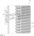
- FIG. 4 the area of the highest load as a result of this thermal cycling is shown for a heat exchanger 38 used in the context of a method according to the invention, in which the associated closure element 40 is positioned in a completely closed position. This area is also exposed to the highest load as a result of thermal cycling in a conventional heat exchanger with U-shaped flow guidance.
- a conventional heat exchanger with a U-shaped flow guide as well as a heat exchanger 38 used in the context of a method according to the invention comprises a heat exchanger block 42 which is formed from a plurality of parallel, spaced-apart heat exchanger tubes 44 (in particular flat tubes) as well as corrugated fins 46 arranged between the heat exchanger tubes 44 and connecting them to one another.
- One end of the heat exchanger tubes 44 open into a first heat exchanger box 48 and the other ends into a second heat exchanger box 58.
- the first heat exchanger box 48 integrates an inlet 50 and an outlet 52 for the coolant.
- the first heat exchanger box is divided into two parts by means of a separating web in a section between the inlet and the outlet.
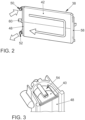
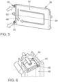
- a heat exchanger 38 which can be used in the context of a method according to the invention, as shown in the Fig. 4 to 9
- a separating web 54 is provided with a through-opening 56, which can be closed (more or less) as required by means of a movable closure element 40.
- a portion of the coolant can flow through the more or less large through-opening 56 released by the closure element 40.
- the closure element 40 is positioned in different positions for switching the cooling system from operation in the small cooling circuit to operation in the large cooling circuit in order to position the location of the highest load due to the thermal cycling accordingly differently, thereby making it possible to increase the number of thermal cycling load cycles to which the heat exchanger can be exposed without causing material failure by a multiple compared to a conventional heat exchanger with a U-shaped flow guide, without having to undertake structural reinforcement measures and without having to reduce the temperature of the coolant flowing into the heat exchanger after the switching valve has been switched.
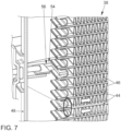
- the Fig. 7 illustrates the shift in the area of the highest load that can be achieved as a result of the thermal cycling along the longitudinal direction of the first heat exchanger box 48 in the direction of the outlet 52.
- This effect is due to the fact that the hot coolant can now be distributed not only within the part of the first heat exchanger box 48 comprising the inlet 50, but also in an amount that depends on the degree to which the first heat exchanger box 48 is closed by the closure element 44, up to at least the upper area of the part of the first heat exchanger box 48 comprising the outlet 52, which is associated with a corresponding shift in the cold-hot front between the differently tempered coolant partial quantities.
- the hot coolant flowing through the through-opening released by the closure element into the part of the first heat exchanger box 48 comprising the outlet 52 can mix with the cold coolant there, which leads to the formation of a mixing zone which, as a result of a reduced average temperature of the coolant contained therein, leads to a further reduction in the thermal cycling stress.
- the area of the highest load due to the associated thermal cycling stress can thus be shifted along the row of heat exchanger tubes 44 opening into the part of the first heat exchanger box 48 comprising the outlet 52, which, since each of these separated areas allows approximately an identical number of load cycles, leads to the already mentioned multiplication of the service life of the heat exchanger 38 (with regard to thermal cycling resistance).
- the Fig. 8 and 9 show a position of the closure element 40 in which the through-opening 56 is opened as far as possible and the degree of closure of the first heat exchanger box 48 by the closure element 40 is thus minimal, whereby the Most of the hot coolant flows directly from the part comprising the inlet 50 into the part comprising the outlet 52 of the first heat exchanger box 48, while only a very small part of it takes the flow path via the heat exchanger tubes 44. In comparison to the positioning according to the Fig. 7 the area of highest stress due to thermal cycling would be shifted even further towards the outlet 52.
- Adjustment of the various positions of the closure element 40 can be achieved by means of an actuator 60, which is controlled for this purpose by a control device, in particular the engine control 36 of the motor vehicle according to the Fig. 1 , can be controlled.
- the actuator 60 can be actuated electrically, pneumatically or hydraulically, for example.
- the Fig. 10 to 12 show schematically different embodiments for an exclusively linearly moving closure element 40.
- the closure element 40 is moved in at least one direction of movement electromagnetically, for example by an armature 64 connected to the closure element 40 and movably guided within an electrical coil 62.
- This movement can be associated with an increasing preload of a spring element 66, which then, when the electrical coil 62 is no longer supplied with electrical voltage, leading to a resetting of the closure element 40.
- a spring element 66 which then, when the electrical coil 62 is no longer supplied with electrical voltage, leading to a resetting of the closure element 40.
- an electromagnetic movement of the closure element 40 in both directions is also possible.
- the Fig. 11 illustrates the possibility of adjusting the closure element 40 in one direction of movement by means of an electric motor drive, while a reset is carried out by a previously pre-tensioned spring element 66.
- a previously pre-tensioned spring element 66 In order to enable the electric motor to be driven in only one direction of rotation, it can be provided that an engagement between a toothing of a pinion 68 driven by the electric motor and a rack 70 connected to the closure element 40 is only provided for a partial range of the rotation of the pinion 68.
- a spring element can be provided in addition, which can be particularly useful for implementing a so-called "failsafe" functionality in which the closure element 40 is brought into the position that closes the first heat exchanger box 48 as far as possible in the event of a failure of the actuator 60, in order to avoid a reduction in the cooling performance during operation of the cooling system as a result of coolant flowing directly from the part comprising the inlet 50 into the part of the first heat exchanger box 48 comprising the outlet 52.
- a spring element 66 which causes or supports a movement of the closure element 40 in at least one direction of movement acts in the direction of an increasingly closing position of the closure element 40.
- pinions 68 can also be driven by means of, for example, a vacuum piston (not shown) or a servo motor in combination with a cable pull (not shown).
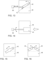
- the closure element 40 can also be moved into different positions by a rotational movement.
- the rotary movement may be provided by a linearly acting actuator 60 (for example according to the Fig. 10 to 12 ), which is at a distance from a pivot joint 72 on the closure element 40.
- a rotating actuator 60 is used, which has a single closure element 40 (cf. Fig. 15 ) or a closure element 40 consisting of two partial elements according to the Fig. 16 rotating.
Landscapes
- Engineering & Computer Science (AREA)
- General Engineering & Computer Science (AREA)
- Mechanical Engineering (AREA)
- Physics & Mathematics (AREA)
- Thermal Sciences (AREA)
- Chemical & Material Sciences (AREA)
- Combustion & Propulsion (AREA)
- Geometry (AREA)
- Cooling, Air Intake And Gas Exhaust, And Fuel Tank Arrangements In Propulsion Units (AREA)
Claims (9)
- Procédé de fonctionnement d'un système de refroidissement qui forme un grand circuit de refroidissement intégrant un échangeur de chaleur (38) et un petit circuit de refroidissement excluant l'échangeur de chaleur (38), l'échangeur de chaleur (38) comprenant une pluralité de tubes d'échangeur de chaleur (44) qui sont prévus pour être traversés par un agent réfrigérant et pour qu'un fluide de refroidissement s'écoule autour de ceux-ci, et des boîtiers d'échangeur de chaleur (48, 58) raccordés aux tubes d'échangeur de chaleur (44) à leurs extrémités, au moins un premier (48) des boîtiers d'échangeur de chaleur présentant une entrée (50) de l'échangeur de chaleur (38) et une sortie (52) de l'échangeur de chaleur (38) pour un guidage d'écoulement en forme de U du fluide de refroidissement, et ce premier boîtier d'échangeur de chaleur (48) pouvant être fermé de manière variable à l'aide d'un élément de fermeture (40) entre l'entrée (50) et la sortie (52), et, pour la commutation d'un fonctionnement du système de refroidissement dans le petit circuit de refroidissement à un fonctionnement dans le grand circuit de refroidissement, une soupape de commutation (28) prévue à l'extérieur de l'échangeur de chaleur étant actionnée, caractérisé en ce que le degré de la fermeture du premier boîtier d'échangeur de chaleur (48) est modifié par réglage de différentes positions de l'élément de fermeture (40) pour au moins deux commutations successives du petit circuit de refroidissement au grand circuit de refroidissement, par le fait que, pour une première commutation du petit circuit de refroidissement au grand circuit de refroidissement, le degré de la fermeture du premier boîtier d'échangeur de chaleur (48) est réglé à une première valeur par réglage d'une première position de l'élément de fermeture (40) et le degré de la fermeture du premier boîtier d'échangeur de chaleur (48) est réglé à une deuxième valeur qui est différente de la première valeur par réglage d'une deuxième position de l'élément de fermeture (40), laquelle est différente de la première position, pour une deuxième commutation, subséquente à la première commutation, du petit circuit de refroidissement au grand circuit de refroidissement.
- Procédé selon la revendication 1, caractérisé en ce qu'après une phase définie d'un fonctionnement du système de refroidissement dans le grand circuit de refroidissement, le premier boîtier d'échangeur de chaleur (48) est fermé dans une très large mesure à l'aide de l'élément de fermeture.
- Procédé selon la revendication 1 ou 2, caractérisé en ce que l'élément de fermeture (40) est déplaçable dans plus de deux positions.
- Procédé selon l'une des revendications 1 à 3, caractérisé en ce que le degré de la fermeture du premier boîtier d'échangeur de chaleur (48) est modifié pour chaque commutation du petit circuit de refroidissement au grand circuit de refroidissement.
- Procédé selon l'une des revendications 1 à 3, caractérisé en ce que le degré de la fermeture du premier boîtier d'échangeur de chaleur (48) est modifié respectivement après un nombre défini de commutations du petit circuit de refroidissement au grand circuit de refroidissement.
- Procédé selon l'une des revendications 1 à 3, caractérisé en ce que le degré de la fermeture du premier boîtier d'échangeur de chaleur (48) est modifié respectivement après une durée de fonctionnement définie du système de refroidissement.
- Procédé selon l'une des revendications précédentes, caractérisé en ce que les différentes positions de l'élément de fermeture, réglées pour la commutation du petit circuit de refroidissement au grand circuit de refroidissement, sont réglées souvent de la même manière.
- Procédé selon l'une des revendications précédentes, caractérisé en ce que le degré de la fermeture du premier boîtier d'échangeur de chaleur (48) par réglage de différentes positions de l'élément de fermeture (48) n'est modifié que lorsque la température de l'agent de refroidissement se trouvant déjà dans l'échangeur de chaleur (38) se situe en dessous d'une valeur limite et/ou la température et/ou le flux volumique de l'agent de refroidissement s'écoulant dans le premier boîtier d'échangeur de chaleur (48) se situent au-dessus d'une valeur limite.
- Procédé selon la revendication 8, caractérisé en ce que le premier boîtier d'échangeur de chaleur (48) est maintenu fermé dans une très large mesure à l'aide de l'élément de fermeture (40), lorsque la température de l'agent de refroidissement se trouvant déjà dans l'échangeur de chaleur (38) se situe au-dessus de la valeur limite correspondante et/ou la température et/ou le flux volumique de l'agent de refroidissement s'écoulant dans le premier boîtier d'échangeur de chaleur (48) se situent en dessous de la valeur limite correspondante.
Applications Claiming Priority (2)
| Application Number | Priority Date | Filing Date | Title |
|---|---|---|---|
| DE102015108599.2A DE102015108599A1 (de) | 2015-06-01 | 2015-06-01 | Verfahren zum Betreiben eines Kühlsystems |
| PCT/EP2016/062112 WO2016193194A1 (fr) | 2015-06-01 | 2016-05-30 | Procédé permettant de faire fonctionner un système de refroidissement |
Publications (2)
| Publication Number | Publication Date |
|---|---|
| EP3303794A1 EP3303794A1 (fr) | 2018-04-11 |
| EP3303794B1 true EP3303794B1 (fr) | 2024-11-20 |
Family
ID=56117683
Family Applications (1)
| Application Number | Title | Priority Date | Filing Date |
|---|---|---|---|
| EP16728259.9A Active EP3303794B1 (fr) | 2015-06-01 | 2016-05-30 | Procédé permettant de faire fonctionner un système de refroidissement |
Country Status (3)
| Country | Link |
|---|---|
| EP (1) | EP3303794B1 (fr) |
| DE (1) | DE102015108599A1 (fr) |
| WO (1) | WO2016193194A1 (fr) |
Families Citing this family (2)
| Publication number | Priority date | Publication date | Assignee | Title |
|---|---|---|---|---|
| FR3066014A1 (fr) * | 2017-05-02 | 2018-11-09 | Valeo Systemes Thermiques | Echangeur de chaleur avec dispositif de protection et procede de fabrication associe |
| DE102019121989A1 (de) * | 2019-08-15 | 2021-02-18 | Volkswagen Aktiengesellschaft | Wärmetauscher und Wärmetauscheranordnung |
Citations (1)
| Publication number | Priority date | Publication date | Assignee | Title |
|---|---|---|---|---|
| DE102005055323A1 (de) * | 2005-11-21 | 2007-05-31 | Audi Ag | Kühleinrichtung und Verfahren zum Betreiben einer Kühleinrichtung und Kühlkreislauf |
Family Cites Families (12)
| Publication number | Priority date | Publication date | Assignee | Title |
|---|---|---|---|---|
| DE3217836A1 (de) * | 1982-05-12 | 1983-11-17 | Volkswagenwerk Ag, 3180 Wolfsburg | Kuehler, insbesondere fuer brennkraftmaschinen |
| FR2673241A1 (fr) * | 1991-02-26 | 1992-08-28 | Valeo Thermique Moteur Sa | Radiateur de vehicule automobile muni d'un dispositif de commande de circulation de fluide. |
| US6019171A (en) * | 1998-11-18 | 2000-02-01 | General Motors Corporation | Down flow, two pass radiator with automatic air venting means |
| DE10010078C2 (de) * | 2000-03-02 | 2003-06-18 | Bayerische Motoren Werke Ag | Kühlvorrichtung für ein flüssiges Betriebsmittel einer Brennkraftmaschine |
| US9557749B2 (en) * | 2001-07-30 | 2017-01-31 | Dana Canada Corporation | Valves for bypass circuits in heat exchangers |
| US7490662B2 (en) * | 2004-10-13 | 2009-02-17 | Visteon Global Technologies, Inc. | Integrated thermal bypass valve |
| DE102005017974A1 (de) * | 2005-04-19 | 2006-11-02 | Audi Ag | Wärmeübertragersystem |
| DE102006061440A1 (de) | 2006-12-23 | 2008-06-26 | Modine Manufacturing Co., Racine | Kühlflüssigkeitskühler |
| DE102006040989A1 (de) | 2006-08-31 | 2007-11-08 | Audi Ag | Kühler mit integriertem Thermostat |
| EP1936316B1 (fr) * | 2006-12-21 | 2011-03-02 | Nissan Motor Manufacturing (UK) Ltd. | Améliorations de réservoirs de radiateurs ou les concernant |
| ITBO20100012A1 (it) * | 2010-01-13 | 2011-07-14 | Ferrari Spa | Sistema di raffreddamento per un veicolo con propulsione ibrida |
| CN103712482B (zh) | 2012-10-02 | 2017-04-12 | 马勒国际公司 | 热交换器 |
-
2015
- 2015-06-01 DE DE102015108599.2A patent/DE102015108599A1/de not_active Withdrawn
-
2016
- 2016-05-30 WO PCT/EP2016/062112 patent/WO2016193194A1/fr not_active Ceased
- 2016-05-30 EP EP16728259.9A patent/EP3303794B1/fr active Active
Patent Citations (1)
| Publication number | Priority date | Publication date | Assignee | Title |
|---|---|---|---|---|
| DE102005055323A1 (de) * | 2005-11-21 | 2007-05-31 | Audi Ag | Kühleinrichtung und Verfahren zum Betreiben einer Kühleinrichtung und Kühlkreislauf |
Also Published As
| Publication number | Publication date |
|---|---|
| EP3303794A1 (fr) | 2018-04-11 |
| WO2016193194A1 (fr) | 2016-12-08 |
| DE102015108599A1 (de) | 2016-12-01 |
Similar Documents
| Publication | Publication Date | Title |
|---|---|---|
| EP2565560B1 (fr) | Système pour un véhicule automobile pour chauffer et/ou refroidir | |
| EP1984195B1 (fr) | Échangeur thermique comprenant un accumulateur de froid | |
| EP3648997B1 (fr) | Installation frigorifique pour véhicule pourvue d'un circuit de réfrigération équipé d'un échangeur thermique et échangeur thermique conçu pour une telle installation frigorifique | |
| EP2021612B1 (fr) | Système de recyclage des gaz d'échappement | |
| DE102017217685B4 (de) | Anordnung zur Temperierung einer Batterie und weiterer elektrischer Komponenten eines Fahrzeugs, Fahrzeug sowie Verfahren zur Steuerung der Anordnung | |
| DE69735216T2 (de) | Adsorptionskältegerät | |
| DE102014215074A1 (de) | Temperieranordnung für Getriebeöl eines Kraftfahrzeugs sowie Verfahren zum Temperieren von Getriebeöl eines Kraftfahrzeugs | |
| DE112012004988T5 (de) | Wärmetauscher | |
| EP2562379B1 (fr) | Circuit d'agent réfrigérant | |
| DE69801472T2 (de) | Abgasanlage für einen Kraftfahrzeugmotor | |
| EP3953652B1 (fr) | Ensemble échangeur de chaleur comprenant au moins un échangeur de chaleur à plusieurs passages et procédé pour faire fonctionner un ensemble échangeur de chaleur | |
| WO2023099251A1 (fr) | Procédé de commande d'un système de refroidissement, dispositif de commande et véhicule automobile | |
| EP2064510B1 (fr) | Echangeur de chaleur a double flux avec canal de derivation integre | |
| DE10102640A1 (de) | Wärmetauscher | |
| WO2023217702A1 (fr) | Système de gestion thermique pour véhicule automobile et véhicule automobile équipé d'un tel système de gestion thermique | |
| DE102006023809B3 (de) | Wärmeübertragungseinheit für Verbrennungskraftmaschinen | |
| DE102007052927A1 (de) | Kühlmittelkreislauf für eine Brennkraftmaschine | |
| DE102005017974A1 (de) | Wärmeübertragersystem | |
| EP2562378A1 (fr) | Stratégie de fonctionnement d'un circuit d'agent réfrigérant séparé | |
| DE102015108599A1 (de) | Verfahren zum Betreiben eines Kühlsystems | |
| DE10012197B4 (de) | Thermomanagement für ein Kraftfahrzeug mit einem Kühlmittelkreislauf und einer Klimaanlage | |
| DE102006061440A1 (de) | Kühlflüssigkeitskühler | |
| EP4067781B1 (fr) | Registre de froid destiné à la génération d'air froid pourvu de dispositif de dégivrage | |
| DE19535782C2 (de) | Klimatisierungsanordnung für Nutzfahrzeuge, insbesondere Omnibusse, mit einem mindestens kühlseitigen Zwischenüberträger | |
| DE102014200668A1 (de) | Flüssigkeitsgekühlte Brennkraftmaschine mit Schaltkulisse und Verfahren zur Steuerung der Schaltkulisse einer derartigen Brennkraftmaschine |
Legal Events
| Date | Code | Title | Description |
|---|---|---|---|
| STAA | Information on the status of an ep patent application or granted ep patent |
Free format text: STATUS: THE INTERNATIONAL PUBLICATION HAS BEEN MADE |
|
| PUAI | Public reference made under article 153(3) epc to a published international application that has entered the european phase |
Free format text: ORIGINAL CODE: 0009012 |
|
| STAA | Information on the status of an ep patent application or granted ep patent |
Free format text: STATUS: REQUEST FOR EXAMINATION WAS MADE |
|
| 17P | Request for examination filed |
Effective date: 20180102 |
|
| AK | Designated contracting states |
Kind code of ref document: A1 Designated state(s): AL AT BE BG CH CY CZ DE DK EE ES FI FR GB GR HR HU IE IS IT LI LT LU LV MC MK MT NL NO PL PT RO RS SE SI SK SM TR |
|
| AX | Request for extension of the european patent |
Extension state: BA ME |
|
| DAV | Request for validation of the european patent (deleted) | ||
| DAX | Request for extension of the european patent (deleted) | ||
| STAA | Information on the status of an ep patent application or granted ep patent |
Free format text: STATUS: EXAMINATION IS IN PROGRESS |
|
| 17Q | First examination report despatched |
Effective date: 20181116 |
|
| APBK | Appeal reference recorded |
Free format text: ORIGINAL CODE: EPIDOSNREFNE |
|
| APBN | Date of receipt of notice of appeal recorded |
Free format text: ORIGINAL CODE: EPIDOSNNOA2E |
|
| APBR | Date of receipt of statement of grounds of appeal recorded |
Free format text: ORIGINAL CODE: EPIDOSNNOA3E |
|
| APAF | Appeal reference modified |
Free format text: ORIGINAL CODE: EPIDOSCREFNE |
|
| APBT | Appeal procedure closed |
Free format text: ORIGINAL CODE: EPIDOSNNOA9E |
|
| RIC1 | Information provided on ipc code assigned before grant |
Ipc: F16K 31/54 20060101ALN20240709BHEP Ipc: F16K 31/06 20060101ALN20240709BHEP Ipc: F16K 31/04 20060101ALN20240709BHEP Ipc: F16K 3/02 20060101ALN20240709BHEP Ipc: F16K 1/22 20060101ALN20240709BHEP Ipc: F28D 21/00 20060101ALN20240709BHEP Ipc: F28F 1/12 20060101ALN20240709BHEP Ipc: F28D 1/053 20060101ALN20240709BHEP Ipc: F01P 7/14 20060101ALN20240709BHEP Ipc: F01P 7/16 20060101ALI20240709BHEP Ipc: F28F 27/02 20060101ALI20240709BHEP Ipc: F28F 9/02 20060101ALI20240709BHEP Ipc: F01P 3/18 20060101ALI20240709BHEP Ipc: F01P 11/16 20060101AFI20240709BHEP |
|
| GRAP | Despatch of communication of intention to grant a patent |
Free format text: ORIGINAL CODE: EPIDOSNIGR1 |
|
| STAA | Information on the status of an ep patent application or granted ep patent |
Free format text: STATUS: GRANT OF PATENT IS INTENDED |
|
| RIC1 | Information provided on ipc code assigned before grant |
Ipc: F16K 31/54 20060101ALN20240718BHEP Ipc: F16K 31/06 20060101ALN20240718BHEP Ipc: F16K 31/04 20060101ALN20240718BHEP Ipc: F16K 3/02 20060101ALN20240718BHEP Ipc: F16K 1/22 20060101ALN20240718BHEP Ipc: F28D 21/00 20060101ALN20240718BHEP Ipc: F28F 1/12 20060101ALN20240718BHEP Ipc: F28D 1/053 20060101ALN20240718BHEP Ipc: F01P 7/14 20060101ALN20240718BHEP Ipc: F01P 7/16 20060101ALI20240718BHEP Ipc: F28F 27/02 20060101ALI20240718BHEP Ipc: F28F 9/02 20060101ALI20240718BHEP Ipc: F01P 3/18 20060101ALI20240718BHEP Ipc: F01P 11/16 20060101AFI20240718BHEP |
|
| INTG | Intention to grant announced |
Effective date: 20240820 |
|
| GRAS | Grant fee paid |
Free format text: ORIGINAL CODE: EPIDOSNIGR3 |
|
| GRAA | (expected) grant |
Free format text: ORIGINAL CODE: 0009210 |
|
| STAA | Information on the status of an ep patent application or granted ep patent |
Free format text: STATUS: THE PATENT HAS BEEN GRANTED |
|
| AK | Designated contracting states |
Kind code of ref document: B1 Designated state(s): AL AT BE BG CH CY CZ DE DK EE ES FI FR GB GR HR HU IE IS IT LI LT LU LV MC MK MT NL NO PL PT RO RS SE SI SK SM TR |
|
| REG | Reference to a national code |
Ref country code: GB Ref legal event code: FG4D Free format text: NOT ENGLISH |
|
| REG | Reference to a national code |
Ref country code: CH Ref legal event code: EP |
|
| P01 | Opt-out of the competence of the unified patent court (upc) registered |
Free format text: CASE NUMBER: APP_58974/2024 Effective date: 20241029 |
|
| REG | Reference to a national code |
Ref country code: DE Ref legal event code: R096 Ref document number: 502016016801 Country of ref document: DE |
|
| REG | Reference to a national code |
Ref country code: IE Ref legal event code: FG4D Free format text: LANGUAGE OF EP DOCUMENT: GERMAN |
|
| REG | Reference to a national code |
Ref country code: LT Ref legal event code: MG9D |
|
| REG | Reference to a national code |
Ref country code: NL Ref legal event code: MP Effective date: 20241120 |
|
| PG25 | Lapsed in a contracting state [announced via postgrant information from national office to epo] |
Ref country code: IS Free format text: LAPSE BECAUSE OF FAILURE TO SUBMIT A TRANSLATION OF THE DESCRIPTION OR TO PAY THE FEE WITHIN THE PRESCRIBED TIME-LIMIT Effective date: 20250320 Ref country code: HR Free format text: LAPSE BECAUSE OF FAILURE TO SUBMIT A TRANSLATION OF THE DESCRIPTION OR TO PAY THE FEE WITHIN THE PRESCRIBED TIME-LIMIT Effective date: 20241120 Ref country code: PT Free format text: LAPSE BECAUSE OF FAILURE TO SUBMIT A TRANSLATION OF THE DESCRIPTION OR TO PAY THE FEE WITHIN THE PRESCRIBED TIME-LIMIT Effective date: 20250320 |
|
| PG25 | Lapsed in a contracting state [announced via postgrant information from national office to epo] |
Ref country code: NL Free format text: LAPSE BECAUSE OF FAILURE TO SUBMIT A TRANSLATION OF THE DESCRIPTION OR TO PAY THE FEE WITHIN THE PRESCRIBED TIME-LIMIT Effective date: 20241120 Ref country code: FI Free format text: LAPSE BECAUSE OF FAILURE TO SUBMIT A TRANSLATION OF THE DESCRIPTION OR TO PAY THE FEE WITHIN THE PRESCRIBED TIME-LIMIT Effective date: 20241120 |
|
| PG25 | Lapsed in a contracting state [announced via postgrant information from national office to epo] |
Ref country code: BG Free format text: LAPSE BECAUSE OF FAILURE TO SUBMIT A TRANSLATION OF THE DESCRIPTION OR TO PAY THE FEE WITHIN THE PRESCRIBED TIME-LIMIT Effective date: 20241120 |
|
| PG25 | Lapsed in a contracting state [announced via postgrant information from national office to epo] |
Ref country code: ES Free format text: LAPSE BECAUSE OF FAILURE TO SUBMIT A TRANSLATION OF THE DESCRIPTION OR TO PAY THE FEE WITHIN THE PRESCRIBED TIME-LIMIT Effective date: 20241120 |
|
| PG25 | Lapsed in a contracting state [announced via postgrant information from national office to epo] |
Ref country code: NO Free format text: LAPSE BECAUSE OF FAILURE TO SUBMIT A TRANSLATION OF THE DESCRIPTION OR TO PAY THE FEE WITHIN THE PRESCRIBED TIME-LIMIT Effective date: 20250220 |
|
| PG25 | Lapsed in a contracting state [announced via postgrant information from national office to epo] |
Ref country code: LV Free format text: LAPSE BECAUSE OF FAILURE TO SUBMIT A TRANSLATION OF THE DESCRIPTION OR TO PAY THE FEE WITHIN THE PRESCRIBED TIME-LIMIT Effective date: 20241120 Ref country code: GR Free format text: LAPSE BECAUSE OF FAILURE TO SUBMIT A TRANSLATION OF THE DESCRIPTION OR TO PAY THE FEE WITHIN THE PRESCRIBED TIME-LIMIT Effective date: 20250221 |
|
| PG25 | Lapsed in a contracting state [announced via postgrant information from national office to epo] |
Ref country code: PL Free format text: LAPSE BECAUSE OF FAILURE TO SUBMIT A TRANSLATION OF THE DESCRIPTION OR TO PAY THE FEE WITHIN THE PRESCRIBED TIME-LIMIT Effective date: 20241120 |
|
| PG25 | Lapsed in a contracting state [announced via postgrant information from national office to epo] |
Ref country code: RS Free format text: LAPSE BECAUSE OF FAILURE TO SUBMIT A TRANSLATION OF THE DESCRIPTION OR TO PAY THE FEE WITHIN THE PRESCRIBED TIME-LIMIT Effective date: 20250220 |
|
| PG25 | Lapsed in a contracting state [announced via postgrant information from national office to epo] |
Ref country code: SM Free format text: LAPSE BECAUSE OF FAILURE TO SUBMIT A TRANSLATION OF THE DESCRIPTION OR TO PAY THE FEE WITHIN THE PRESCRIBED TIME-LIMIT Effective date: 20241120 |
|
| PGFP | Annual fee paid to national office [announced via postgrant information from national office to epo] |
Ref country code: DE Payment date: 20250531 Year of fee payment: 10 |
|
| PG25 | Lapsed in a contracting state [announced via postgrant information from national office to epo] |
Ref country code: DK Free format text: LAPSE BECAUSE OF FAILURE TO SUBMIT A TRANSLATION OF THE DESCRIPTION OR TO PAY THE FEE WITHIN THE PRESCRIBED TIME-LIMIT Effective date: 20241120 |
|
| PG25 | Lapsed in a contracting state [announced via postgrant information from national office to epo] |
Ref country code: EE Free format text: LAPSE BECAUSE OF FAILURE TO SUBMIT A TRANSLATION OF THE DESCRIPTION OR TO PAY THE FEE WITHIN THE PRESCRIBED TIME-LIMIT Effective date: 20241120 |
|
| PG25 | Lapsed in a contracting state [announced via postgrant information from national office to epo] |
Ref country code: RO Free format text: LAPSE BECAUSE OF FAILURE TO SUBMIT A TRANSLATION OF THE DESCRIPTION OR TO PAY THE FEE WITHIN THE PRESCRIBED TIME-LIMIT Effective date: 20241120 |
|
| PG25 | Lapsed in a contracting state [announced via postgrant information from national office to epo] |
Ref country code: SK Free format text: LAPSE BECAUSE OF FAILURE TO SUBMIT A TRANSLATION OF THE DESCRIPTION OR TO PAY THE FEE WITHIN THE PRESCRIBED TIME-LIMIT Effective date: 20241120 |
|
| PG25 | Lapsed in a contracting state [announced via postgrant information from national office to epo] |
Ref country code: CZ Free format text: LAPSE BECAUSE OF FAILURE TO SUBMIT A TRANSLATION OF THE DESCRIPTION OR TO PAY THE FEE WITHIN THE PRESCRIBED TIME-LIMIT Effective date: 20241120 |
|
| PG25 | Lapsed in a contracting state [announced via postgrant information from national office to epo] |
Ref country code: IT Free format text: LAPSE BECAUSE OF FAILURE TO SUBMIT A TRANSLATION OF THE DESCRIPTION OR TO PAY THE FEE WITHIN THE PRESCRIBED TIME-LIMIT Effective date: 20241120 |
|
| REG | Reference to a national code |
Ref country code: DE Ref legal event code: R097 Ref document number: 502016016801 Country of ref document: DE |
|
| PG25 | Lapsed in a contracting state [announced via postgrant information from national office to epo] |
Ref country code: SE Free format text: LAPSE BECAUSE OF FAILURE TO SUBMIT A TRANSLATION OF THE DESCRIPTION OR TO PAY THE FEE WITHIN THE PRESCRIBED TIME-LIMIT Effective date: 20241120 |
|
| PLBE | No opposition filed within time limit |
Free format text: ORIGINAL CODE: 0009261 |
|
| STAA | Information on the status of an ep patent application or granted ep patent |
Free format text: STATUS: NO OPPOSITION FILED WITHIN TIME LIMIT |
|
| 26N | No opposition filed |
Effective date: 20250821 |
|
| REG | Reference to a national code |
Ref country code: CH Ref legal event code: H13 Free format text: ST27 STATUS EVENT CODE: U-0-0-H10-H13 (AS PROVIDED BY THE NATIONAL OFFICE) Effective date: 20251223 |
|
| PG25 | Lapsed in a contracting state [announced via postgrant information from national office to epo] |
Ref country code: LU Free format text: LAPSE BECAUSE OF NON-PAYMENT OF DUE FEES Effective date: 20250530 |
|
| PG25 | Lapsed in a contracting state [announced via postgrant information from national office to epo] |
Ref country code: CH Free format text: LAPSE BECAUSE OF NON-PAYMENT OF DUE FEES Effective date: 20250531 |
|
| GBPC | Gb: european patent ceased through non-payment of renewal fee |
Effective date: 20250530 |
|
| REG | Reference to a national code |
Ref country code: BE Ref legal event code: MM Effective date: 20250531 |
|
| PG25 | Lapsed in a contracting state [announced via postgrant information from national office to epo] |
Ref country code: MC Free format text: LAPSE BECAUSE OF FAILURE TO SUBMIT A TRANSLATION OF THE DESCRIPTION OR TO PAY THE FEE WITHIN THE PRESCRIBED TIME-LIMIT Effective date: 20241120 |
|
| PG25 | Lapsed in a contracting state [announced via postgrant information from national office to epo] |
Ref country code: GB Free format text: LAPSE BECAUSE OF NON-PAYMENT OF DUE FEES Effective date: 20250530 |
|
| PG25 | Lapsed in a contracting state [announced via postgrant information from national office to epo] |
Ref country code: IE Free format text: LAPSE BECAUSE OF NON-PAYMENT OF DUE FEES Effective date: 20250530 |
|
| PG25 | Lapsed in a contracting state [announced via postgrant information from national office to epo] |
Ref country code: BE Free format text: LAPSE BECAUSE OF NON-PAYMENT OF DUE FEES Effective date: 20250531 |
|
| PG25 | Lapsed in a contracting state [announced via postgrant information from national office to epo] |
Ref country code: FR Free format text: LAPSE BECAUSE OF NON-PAYMENT OF DUE FEES Effective date: 20250531 |