EP3304021B1 - Dispositif servant à détecter une pression d'un milieu fluide et procédé servant à fabriquer le dispositif - Google Patents
Dispositif servant à détecter une pression d'un milieu fluide et procédé servant à fabriquer le dispositif Download PDFInfo
- Publication number
- EP3304021B1 EP3304021B1 EP16717861.5A EP16717861A EP3304021B1 EP 3304021 B1 EP3304021 B1 EP 3304021B1 EP 16717861 A EP16717861 A EP 16717861A EP 3304021 B1 EP3304021 B1 EP 3304021B1
- Authority
- EP
- European Patent Office
- Prior art keywords
- pressure
- housing
- sensor module
- housing part
- sensor element
- Prior art date
- Legal status (The legal status is an assumption and is not a legal conclusion. Google has not performed a legal analysis and makes no representation as to the accuracy of the status listed.)
- Active
Links
Images


Classifications
-
- G—PHYSICS
- G01—MEASURING; TESTING
- G01L—MEASURING FORCE, STRESS, TORQUE, WORK, MECHANICAL POWER, MECHANICAL EFFICIENCY, OR FLUID PRESSURE
- G01L13/00—Devices or apparatus for measuring differences of two or more fluid pressure values
- G01L13/02—Devices or apparatus for measuring differences of two or more fluid pressure values using elastically-deformable members or pistons as sensing elements
- G01L13/025—Devices or apparatus for measuring differences of two or more fluid pressure values using elastically-deformable members or pistons as sensing elements using diaphragms
-
- G—PHYSICS
- G01—MEASURING; TESTING
- G01L—MEASURING FORCE, STRESS, TORQUE, WORK, MECHANICAL POWER, MECHANICAL EFFICIENCY, OR FLUID PRESSURE
- G01L19/00—Details of, or accessories for, apparatus for measuring steady or quasi-steady pressure of a fluent medium insofar as such details or accessories are not special to particular types of pressure gauges
- G01L19/14—Housings
- G01L19/142—Multiple part housings
- G01L19/143—Two part housings
-
- G—PHYSICS
- G01—MEASURING; TESTING
- G01L—MEASURING FORCE, STRESS, TORQUE, WORK, MECHANICAL POWER, MECHANICAL EFFICIENCY, OR FLUID PRESSURE
- G01L19/00—Details of, or accessories for, apparatus for measuring steady or quasi-steady pressure of a fluent medium insofar as such details or accessories are not special to particular types of pressure gauges
- G01L19/14—Housings
- G01L19/147—Details about the mounting of the sensor to support or covering means
-
- G—PHYSICS
- G01—MEASURING; TESTING
- G01L—MEASURING FORCE, STRESS, TORQUE, WORK, MECHANICAL POWER, MECHANICAL EFFICIENCY, OR FLUID PRESSURE
- G01L19/00—Details of, or accessories for, apparatus for measuring steady or quasi-steady pressure of a fluent medium insofar as such details or accessories are not special to particular types of pressure gauges
- G01L19/14—Housings
- G01L19/148—Details about the circuit board integration, e.g. integrated with the diaphragm surface or encapsulation
-
- H—ELECTRICITY
- H10—SEMICONDUCTOR DEVICES; ELECTRIC SOLID-STATE DEVICES NOT OTHERWISE PROVIDED FOR
- H10W—GENERIC PACKAGES, INTERCONNECTIONS, CONNECTORS OR OTHER CONSTRUCTIONAL DETAILS OF DEVICES COVERED BY CLASS H10
- H10W72/00—Interconnections or connectors in packages
- H10W72/01—Manufacture or treatment
- H10W72/015—Manufacture or treatment of bond wires
- H10W72/01515—Forming coatings
-
- H—ELECTRICITY
- H10—SEMICONDUCTOR DEVICES; ELECTRIC SOLID-STATE DEVICES NOT OTHERWISE PROVIDED FOR
- H10W—GENERIC PACKAGES, INTERCONNECTIONS, CONNECTORS OR OTHER CONSTRUCTIONAL DETAILS OF DEVICES COVERED BY CLASS H10
- H10W72/00—Interconnections or connectors in packages
- H10W72/071—Connecting or disconnecting
- H10W72/075—Connecting or disconnecting of bond wires
-
- H—ELECTRICITY
- H10—SEMICONDUCTOR DEVICES; ELECTRIC SOLID-STATE DEVICES NOT OTHERWISE PROVIDED FOR
- H10W—GENERIC PACKAGES, INTERCONNECTIONS, CONNECTORS OR OTHER CONSTRUCTIONAL DETAILS OF DEVICES COVERED BY CLASS H10
- H10W72/00—Interconnections or connectors in packages
- H10W72/50—Bond wires
- H10W72/531—Shapes of wire connectors
- H10W72/5363—Shapes of wire connectors the connected ends being wedge-shaped
-
- H—ELECTRICITY
- H10—SEMICONDUCTOR DEVICES; ELECTRIC SOLID-STATE DEVICES NOT OTHERWISE PROVIDED FOR
- H10W—GENERIC PACKAGES, INTERCONNECTIONS, CONNECTORS OR OTHER CONSTRUCTIONAL DETAILS OF DEVICES COVERED BY CLASS H10
- H10W72/00—Interconnections or connectors in packages
- H10W72/851—Dispositions of multiple connectors or interconnections
- H10W72/874—On different surfaces
- H10W72/884—Die-attach connectors and bond wires
Definitions
- the invention relates to a device for detecting a pressure of a fluid medium and to a method for producing the device.
- Such devices are used for example in automotive technology, for example in particulate filters, in particular in diesel particulate filters, or for particulate filters or in engine control systems with particulate filter and in a low-pressure exhaust gas recirculation.
- the invention is basically conceivable in other applications.
- a pressure measuring module for detecting an absolute pressure or a relative pressure is known.
- the pressure measuring module comprises a preferably manufactured as a premold housing in which a Druckmesschip is added. This is contacted either with a stamped grid or with at least one conductor electrically, wherein at least one electronic component is provided, which is connected to a side of the prefabricated preferably made of housing housing portion of the lead frame or the at least one conductor track and by a subdivision of a lid is covered.
- a device for pressure measurement which has a housing in which a carrier provided with a sensor element and with electrical connection elements is arranged.
- the Pressure channel of a first pressure port connected first housing space and a sealed relative to the first housing space, at least surrounding the electrical connection elements second housing space.
- the housing has a third housing space which is sealed off from the first housing space and the second housing space and which is connected to a second pressure channel of a second pressure port.
- a device for detecting a pressure of a fluid medium has at least one housing with at least one pressure chamber. At least one pressure sensor element is received in the pressure chamber. The device furthermore has at least one compensating element between the housing and the pressure sensor element for compensation of thermo-mechanical stresses. The pressure sensor element is at least partially connected to the compensation element.
- the compensating element has at least one first opening. The pressure sensor element can be acted upon via the first opening with a first pressure.
- the compensating element also has at least one second opening. About the second opening of the pressure chamber and the pressure sensor element can be acted upon with at least a second pressure.
- the devices include a circuit carrier having a ceramic substrate.
- a circuit carrier having a ceramic substrate.
- such a design can lead to a high space requirement. This can be associated in particular with high production costs.
- a device for detecting a pressure of a fluid medium and a method for producing the device are proposed, which at least largely avoid the above-mentioned problems of known devices and methods.
- the term "pressure” designates in particular a partial pressure and / or an absolute pressure and / or a differential pressure and / or a pressure profile and / or a pressure development, for example over time.
- the pressure may also be a plurality of pressures, for example a difference of several pressures.
- the device can thus be in particular a differential pressure measuring device, ie a device which is set up to detect a difference between a first pressure p 1 , for example in a first pressure chamber, and a second pressure p 2 , for example in a second pressure chamber.
- one of these pressure chambers may be a reference pressure chamber, for example a room with atmospheric pressure.
- other embodiments are possible.
- fluid medium in the context of the present invention is basically any substance in the fluid, in particular gaseous state to understand.
- it may be a substance which does not resist any slow shear.
- the fluid state can be temperature and / or pressure dependent.
- the fluid medium can be present as a pure substance or as a substance mixture.
- the device for detecting a pressure of a fluid medium comprises at least one housing with at least two pressure feeders and at least one sensor module.
- the sensor module is accommodated in the housing.
- the sensor module comprises at least one carrier element, at least one pressure sensor element for detecting the pressure and at least one control and evaluation unit.
- the carrier element has at least one substrate and at least one molding compound. Furthermore, the carrier element has at least one passage opening, which completely penetrates the carrier element.
- the pressure sensor element comprises at least one membrane. The pressure sensor element covers the passage opening.
- the control and evaluation is at least partially enclosed by the molding compound.
- housing in the context of the present invention basically refers to an arbitrarily shaped element, which is designed to completely or partially enclose components of the device and to further protect these components from external influences such as mechanical stress or moisture.
- the housing may comprise at least a first housing part, in particular a housing base, and at least one second housing part, in particular a housing cover.
- the first housing part and the second housing part can be materially connected to one another.
- first and second housing part are to be regarded as pure designations, without indicating a ranking and without precluding, for example, the possibility that several types of first housing parts and several types of second housing parts or each of exactly one type may be provided. Furthermore, additional housing parts, for example, third housing parts, may be present.
- the device may further comprise at least one sealing material.
- the sealing material may be configured to connect the first housing part and the second housing part with each other.
- the sealing material may be further configured to connect the sensor module to the housing.
- the sealing material may comprise at least one material selected from the group consisting of: an adhesive, an adhesive sheet, an interference fit with an elastomer.
- adheresive basically refers to a process material which is in particular designed to connect components to one another in a material-locking and preferably irreversible manner.
- the adhesive may preferably be arranged to be applied in a liquid state or viscous state to the respective components and subsequently to a solid state by a physically setting process and / or by a chemically curing process.
- adhesive film basically refers to a film which comprises an adhesive.
- the film may be made of a plastic material.
- the housing may include at least one receptacle for receiving the sensor module.
- the recording may be a depression.
- the sensor module may be secured in the receptacle by means of the sealing material.
- the housing may surround at least one pressure chamber and at least one circuit space.
- the pressure chamber can be sealed off from the circuit space.
- At least one electronic component can be accommodated in the circuit space.
- the sensor module may be partially disposed in the pressure space and partially in the circuit space and sealed against the housing.
- the "pressure space” can be any space which preferably does not comprise any electronic components and is at least partially closed, in particular with respect to an environment.
- the pressure chamber may in particular be a space in which there is at least one pressure of the fluid medium which is detected by the device.
- circuit space designates in principle any space which is at least partially closed, in particular with respect to the environment, and in which at least one electronic component can be accommodated.
- the electronic components of the circuit space may be configured to apply at least one electric current and / or at least one electrical voltage to the pressure sensor element.
- the housing includes at least two pressure feeds. According to the invention, this is a first pressure feed and a second pressure feed.
- first and second print feeds are to be considered as pure labels without precedence and, for example, without precluding the possibility that several types of first print feeds and several types of second print feeds, or just one type in each case, may be provided.
- additional pressure feeds for example third pressure feeds, may be present in the device.
- the first pressure supply can be acted upon by a first pressure.
- a first pressure can be understood as any pressure of the fluid medium; in principle, an external pressure or a reference pressure, for example the pressure of an external air, can also be understood as the first pressure.
- the pressure sensor element can be connected via the first pressure supply to the fluid medium, which has the first pressure, in such a way that the first pressure can be detected by the pressure sensor element.
- the pressure sensor element with at least a second pressure can be acted upon.
- the second pressure can in principle be defined as the first pressure.
- the second pressure may preferably differ from the first pressure, but may also coincide with the first pressure, for example also for carrying out a calibration and / or an adjustment.
- the carrier element has at least one substrate and at least one molding compound.
- the substrate may comprise at least one circuit carrier.
- circuit carrier basically denotes any element which can be designed to carry and / or to include at least one drive and / or at least one evaluation circuit, for example an electrical and / or electronic circuit.
- the circuit carrier may be, for example, a ceramic circuit carrier.
- the circuit carrier may for example be wholly or partially designed as a printed circuit board or comprise at least one printed circuit board. Other embodiments are conceivable in principle.
- molding compound basically refers to any material which, in an initial state, can be subjected to a molding process in a mold or a tool.
- it may be a curable material or mixture of materials, which may be formed in an initial state to then cure and remain dimensionally stable.
- the molding compound may comprise at least one plastic or a plastic mixture or at least one starting material for a Plastic include.
- the molding compound may comprise at least one flow resin and / or a synthetic resin. Other materials are conceivable.
- the molding compound can be designed to at least partially surround the substrate together with the components.
- the molding compound may be configured to protect the components from damage due to mechanical damage, contamination or the like.
- the molding compound can be designed such that the membrane is at least partially uncovered by the molding compound.
- the carrier element further has at least one passage opening, which completely penetrates the carrier element.
- a "passage opening” may in particular be understood as meaning an opening which adjoins at least two sides a further opening and / or an open space and / or is at least fluidically connected.
- the passage opening may be or comprise a passage bore.
- the passage opening may comprise at least one recess of the molding compound and at least one hole of the substrate.
- the hole may in principle have any cross-section, for example a round, an oval or a polygonal cross-section. Other cross sections are conceivable in principle.
- the passage opening may further comprise at least one channel which is delimited by the molding compound.
- a "channel” is to be understood as meaning, in particular, an elongate cavity which extends from at least one first opening to at least one second opening.
- the channel may in principle have any cross section, for example a round, oval or polygonal cross section.
- the term "pressure sensor element” designates in principle any desired sensor element which is set up to detect at least one pressure of a fluid medium.
- the pressure sensor element may in particular be a chip.
- the pressure sensor element may be, for example, a pressure sensor, as it may consist of Robert Bosch GmbH: Sensors in the motor vehicle, 1st edition, 2010, pages 80-82 , is known.
- the pressure sensor element can preferably be a membrane sensor, which in particular has a thin membrane as mechanical Intermediate can have, for example, which is exposed to the pressure of the fluid medium on one side and bends more or less under this influence.
- other pressure sensor elements may alternatively or additionally be used, for example pressure sensor elements based on a piezoelectric effect and / or pressure sensor elements based on an elongation of at least one strain-dependent electrical resistance.
- a "membrane” in the sense of the present invention is to be understood as meaning any element having an elongate shape and a thickness, wherein an extension of the element in the lateral dimension exceeds the thickness of the element, for example by a factor of 20, preferably by one Factor of 50, or preferably by a factor of 100.
- the membrane may be wholly or partly made of a flexible material or entirely or partially of a rigid material.
- the membrane can be designed differently permeable for different substances.
- the membrane may be at least substantially impermeable to at least one or more substances.
- the membrane may be permeable to at least one or more substances in one direction.
- the membrane may be permeable to at least one or more substances in both directions.
- Other embodiments are possible in principle.
- the pressure sensor element can furthermore be completely or partially covered with a first protective material.
- the first protective material may be configured to provide protection of a pressure sensor element from external influences.
- the first protective material may comprise a gel and / or another deformable mass of a plastic or flowable material.
- control and evaluation referred to in the context of the present invention, an electrical and / or electronic circuit which is adapted to at least one signal, in particular an electrical signal to detect and / or set.
- the tax and Evaluation unit having at least one application-specific integrated circuit and / or at least one capacitor.
- Other embodiments are conceivable in principle.
- the substrate of the carrier element may comprise conductor tracks.
- the term "conductor tracks" basically refers to electrically conductive connections with a two-dimensional course, for example in one plane of the substrate. Tracks can be used to connect electronic components.
- the tracks may be made of gold, for example. Other materials are also conceivable.
- the sensor element and the control and evaluation unit can be connected to the conductor tracks. In particular, the sensor element and / or the control and evaluation unit may have bonding pads which are electrically connected to bonding surfaces of the conductor tracks.
- the bonding surfaces of the conductor tracks can be at least partially covered by a second protective material.
- the second protective material may be arranged to provide protection of the bonding surfaces from external influences.
- the second protective material may comprise, for example, a resin, in particular an epoxy resin.
- first and second protective material are to be considered as pure labels without precedence and, for example, without precluding the possibility that multiple types of first protective materials and multiple types of second protective materials, or each of exactly one type, may be provided. Furthermore, additional protective materials, for example third protective materials, may be present.
- the device may further comprise at least one electrical connection, in particular at least one plug.
- the sensor module can be electrically connected to the electrical connection.
- the sensor module can be connected in particular by at least one contact with the electrical connection.
- the contacting may comprise an electrically conductive adhesive.
- the method may include the method steps described below.
- the method steps can be carried out, for example, in the predetermined order. However, another order is also conceivable.
- one or more method steps can be performed simultaneously or temporally overlapping.
- one, several or all of the method steps can be carried out simply or repeatedly.
- the method may additionally comprise further method steps.
- the step b) may include a positive connection of the sensor module with the first housing part, in particular a gluing of the sensor module in the first housing part.
- the step b) may further include introducing at least one sealing material between the first housing part and the sensor module.
- the sensor module can be integrally introduced into the first housing part.
- the step b) may further comprise establishing an electrical connection between the sensor module and at least one electrical connection of the device.
- the electrical connection can be made by means of at least one electrically conductive adhesive.
- Step c) may include introducing at least one sealing material between the sensor module and the first housing part.
- the proposed device for detecting a pressure of a fluid medium and the method for producing the device have numerous advantages over known devices and methods.
- the carrier element which comprises the substrate and the molding compound
- a significant potential for saving compared with a ceramic carrier can result, since an area requirement can generally be reduced by about half.
- the sensor module can have a technical advantage since the application-specific integrated circuit and the capacitors are injected into the molding compound and thus protected from media.
- only one mounting of the pressure sensor element on the passage opening of the carrier element may be necessary.
- the pressure sensor element may in particular be a chip with a membrane and with gold bond pads, which may be well protected against aggressive media in particular.
- the sensor module When introducing the sensor module into the housing, in particular into the first housing part, the sensor module can be simultaneously installed and contacted in the housing with the aid of the sealing material, in particular the sealing adhesive and / or conductive adhesive. By allowing the sealing materials to have a similar coefficient of thermal expansion, mechanical stresses that could affect the sensor module can be avoided.
- the conductive adhesive can be used, for example, to produce a direct electrical contacting in an adhesive and joining surface. For example, by means of the at least one conductive adhesive, a direct electrical contact with the at least one electrical connection, which will be explained in more detail below, be prepared.
- the same sealing material in particular the same sealing adhesive, can be used as for the gluing of the sensor module and be guided in the form of an eight across the module, thereby forming two separate chambers can arise.
- a cost advantage can be brought to bear particularly well by the described construction of the device.
- the sensor module with the Goldbondpads can be glued within the recess of the molding compound on the channel formed by the molding compound and be connected by the bonding wires, in particular by Goldbonddrähte, with the tracks on the circuit board.
- the free-standing bonding surfaces on the printed circuit board and the bonding pads can be protected after a bonding process by the second protective material, in particular by a diffusion-tight Epoxidharzverguss.
- the bonding wires and the pressure sensor element may be covered in the recess by the first protective material, in particular by a pressure-transmitting gel.
- the application-specific integrated circuit can be designed for signal evaluation and can be completely or at least partially embedded with the bonding wires in the molding compound and protected by a measuring medium, for example exhaust gas. Likewise, the capacitors may be embedded in the molding compound.
- contact surfaces of the sensor module after insertion into the first housing part generally can not be accessible from above, they can not be connected in principle with conventional methods, such as soldering or wire bonding, with plug contacts of the housing. Instead, the sealing material and the electrical connection with a conductive adhesive or a conductive adhesive film can be produced simultaneously in one operation.
- the method for producing the device can in principle be substantially simplified. So far, an adhesion of the sensor module was basically cured only to allow the subsequent bonding process.
- the sealing material can first be successively attached to a seal of the housing and the conductive adhesive, then the sensor module placed on, and then the sealing material to a seal of the second housing part be applied. All sealing materials and / or conductive adhesives can be cured together.
- Figure 1A shows an exemplary embodiment of a sensor module 110.
- the sensor module 110 is in Figure 1A shown in a sectional view.
- FIG. 1B shows an exemplary circuit diagram of the sensor module 110.
- the sensor module 110 comprises at least one carrier element 112 which has at least one substrate 114 and at least one molding compound 116.
- the molding compound 116 is preferably in a cured state in use of the sensor module 110.
- the substrate 114 may include a circuit board 118.
- the substrate 114 may further have a cuboid or plate-like basic shape.
- a foil shape is conceivable.
- the substrate 114 may be wholly or partially made of a ceramic material. Other materials are also conceivable, for example a glass fiber reinforced plastic material and / or a polyimide.
- the molding compound 116 may include, for example, a flowable or synthetic resin and may be configured to at least partially enclose the substrate 114.
- the carrier element 112 further has at least one passage opening 120, which completely penetrates the carrier element 112.
- the passage opening 120 of the carrier element 112 may comprise at least one recess 122 of the molding compound and at least one opening 124 of the substrate 114.
- the passage opening may further comprise at least one channel 126, which is bounded by the molding compound 116.
- the sensor module 110 further has at least one pressure sensor element 128 for detecting the pressure.
- the pressure sensor element 128 comprises at least one membrane 130.
- the pressure sensor element 128 covers the passage opening 120.
- the pressure sensor element 128 may be completely or partially covered with a first protective material 132.
- the first protection material 132 may be configured to provide protection of the pressure sensing element 128 from external influences.
- the first protective material 132 may in particular comprise a gel.
- the sensor module 110 may further comprise at least one control and evaluation unit 134.
- the control and evaluation unit 134 may be configured to detect at least one signal and / or set.
- the control and evaluation unit 134 is at least partially enclosed by the molding compound 116.
- the control and evaluation unit 134 may have at least one application-specific integrated circuit 136 (ASIC) and / or at least one capacitor 138.
- ASIC application-specific integrated circuit
- the substrate 114 may include conductive traces 140.
- the tracks 140 may be made of gold.
- the pressure sensor element 128 and the control and evaluation unit 134 may be connected to the tracks 140.
- the pressure sensor element 128 and the control and evaluation unit 134 may have bonding pads, which are electrically connected by bonding wires 142 to bonding surfaces of the conductor tracks 140.
- the bonding surfaces of the conductor tracks 140 may be at least partially covered by a second protective material 144.
- the second protection material 144 may be configured to provide protection of the bonding surfaces from external influences.
- the second protective material 144 may comprise a resin, in particular an epoxy resin.
- FIG. 1B shows an exemplary circuit diagram of the sensor module 110.
- the sensor module 110 may, for example, the in FIG. 1B correspond to the proposed sensor module 110, so that reference may be made largely to the above description.
- the sensor module 110 comprises at least one pressure sensor element 128 and at least one control and evaluation unit 134.
- the pressure sensor element may for example be based on at least one pressure or strain-dependent electrical resistance which can be influenced by the pressure, which is evaluated, for example, by means of at least one bridge circuit 129 in order to generate or detect a pressure signal.
- the control and evaluation unit 134 can, as stated above, have at least one application-specific integrated circuit 136 and, for example, at least four capacitors 138.
- pressure sensor elements 128 and / or control and evaluation units 134 can be used.
- One or more pressure sensing elements 128 may be connected to one or more application specific integrated circuits (ASIC) 136.
- ASIC application specific integrated circuits
- the sensor module 110 may further comprise a temperature sensor element, such as an NTC resistor.
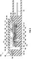
- FIG. 2 shows an exemplary embodiment of a device according to the invention 146 for detecting a pressure of a fluid medium.
- the device 146 is in FIG. 2 shown in a sectional view.
- the device 146 comprises at least one sensor module 110.
- the sensor module 110 corresponds to the arrangement according to FIG Figure 1A , so largely on the description of the Figure 1A can be referred to above.
- the device 146 comprises at least one housing 148.
- the housing 148 comprises a first housing part 150 and at least one second housing part 152.
- the first housing part 150 may be a housing base 154.
- the second housing part 152 may be a housing cover 156 in particular.
- the first housing part 150 and the second housing part 152 are integrally connected to one another.
- the device 146 may include at least one sealing material 158.
- the sealing material 158 may in particular be designed to connect the first housing part 150 and the second housing part 152 to one another.
- the sealing material 158 may be configured to connect the sensor module 110 to the housing 148.
- the housing 148 may include at least one receptacle 160 for receiving the sensor module 110.
- the receptacle 116 may be a depression 162.
- the sensor module 110 may be secured in the receptacle 160 by means of the sealing material 158.
- the sealing material 158 may have completely or partially electrically conductive properties and / or can through at least one electrically conductive adhesive 172 be supplemented, as in FIG. 2 indicated.
- This electrically conductive adhesive may be designed, for example, wholly or partly as an electrically conductive adhesive composition and / or as an electrically conductive adhesive film.
- the housing 148 may enclose at least one pressure space 164 and at least one circuit space 166.
- the pressure space 164 can be sealed off from the circuit space 166, for example by the sealing material 158 and / or at least one web 159, which is placed, for example, from the housing cover 156 on the sensor module 110 and is sealed against the sensor module 110 by the sealing material 158. By means of this web 159, the sensor module 110 can thus additionally be mechanically fixed.
- At least one electrical component may be accommodated in the circuit space 166.
- the sensor module 110 may be partially disposed in the pressure space 164 and partially in the circuit space 166 and sealed against the housing 148.
- the at least one capacitor 138 may be disposed in the circuit space 166.
- the housing 148 further comprises at least two pressure feeds 168, 169.
- a first pressure feed 168 may be connected to the pressure space 164 and a second pressure feed 169 may be connected to the channel 126.
- the pressure sensor element 128 may be fed from the top 174 via the first pressure feed 168 be acted upon with a first pressure p 1 and from the bottom 176 ago via the second pressure supply 169 with a second pressure p. 2
- the pressure sensor element 128 can thus deform, for example, according to the difference p 1 -p 2 , wherein the deformation is electrically detectable.
- FIG. 3 shows a plan view of the device 146 without second housing part 152 and housing cover 156 and without sensor module 110.
- FIG. 4 shows a plan view of the device 146 without second housing part 152 or housing cover 156 and sensor module 110th
- FIG. 5 shows a sectional view of the device 146th
- the sensor module 110 is placed inverted in the housing 148, as described in more detail below.
- the pressure sensor module 110 is connected to the first housing part 150 by means of the sealing material 158. More specifically, the sealing material 158 is connected to the molding compound 116 and the first housing part 150.
- the pressure sensing element 128 has a top 174 and a bottom 176.
- the membrane 130 is located on the upper side 174.
- the underside 176 faces the substrate 114.
- a first pressure channel 178 and a second pressure channel 180 is formed in the first housing part 150 and the housing base 154.
- the first pressure channel 178 is connected to the first pressure supply 168 and the second pressure channel 180 is connected to the second pressure supply 169.
- the pressure sensor module 110 is received in the housing 148 such that the top 174 first housing part 150 and the housing base 15 faces.
- the first pressure channel 178 is designed such that the pressure sensor element 128 can be acted upon from the underside 176 with a first pressure p 1 , as described in more detail below.
- the second pressure channel 180 is configured such that the pressure sensor element 128 can be acted upon by a second pressure p 2 from the top side 174, as described in more detail below.
- the first pressure channel 178 is formed substantially U-shaped with a bottom portion 182 and two leg portions 184.
- the leg portions 184 are oriented perpendicular to the bottom portion 182.
- the leg portions 184 extend upwards.
- the leg sections 184 extend laterally next to the receptacle 160 and are bounded by walls 186. As a result, in an inserted state, the pressure sensor module 110 is located between the leg portions 184, as in FIG FIG. 4 easy to recognize.
- the leg portions 184 are laterally formed adjacent to the pressure sensor module 110.
- the leg portions 184 are formed with a length such that they are in a space 188 above the pressure sensor module 110 with respect to the representation of FIG. 4 lead.
- a fluid medium can reach the bottom section 182 through the first pressure feed 168 into the first pressure channel 178 and, more precisely, laterally relative to the housing 148. From the bottom portion 182, the fluid medium may enter the leg portions 184.
- the fluid medium may enter the space 188. Since the pressure sensor module 110 is disposed inverted in the housing 148 as compared to the previous embodiments, the fluid medium may pass from the space 188 through the opening 124 in the substrate 114 and the channel 126 in the molding compound 116 to the bottom 176 of the pressure sensor element 128 ,
- the second pressure channel 180 extends between the two leg portions 184.
- the second pressure channel 180 is structurally and spatially separated from the first pressure channel 178.
- the second pressure channel 180 extends with respect to the illustration of FIG. 3 above the bottom portion 182 of the first pressure channel 178.
- the second pressure channel 180 is formed in the housing space 164 and extends straight into the receptacle 160 inside.
- second pressure channel 180 is formed as a recess 190 in the receptacle 160.
- a fluid medium through the second pressure supply 169 in the second pressure channel 180 and more precisely from the side relative to the representation of FIG. 3 first enter the pressure chamber 164. From the pressure chamber 164, the fluid medium can enter the second pressure channel 180. Since the pressure sensor module 110 is arranged inverted in the housing 148 in comparison to the previous embodiments, the fluid medium from the second pressure channel 180 can reach the top 176 of the pressure sensor element 128.
- the pressure chamber 164 is bounded by walls 192 laterally.
- the circuit space 166 is also bounded laterally by walls 194.
- the walls 192 of the pressure chamber 164 and the walls 194 of the circuit space 166 are of the walls 186 of the leg portions 184 each spaced by a gap 196.
- the pressure chamber 164 may be sealed relative to the circuit space 166, for example by the sealing material 158 and / or two webs 159, which are placed, for example, from the housing cover 156 on the sensor module 110 and sealed against the sensor module 110 by the sealing material 158.
- a web 159 engages in each case a gap 196.
- At least one electrical component may be accommodated in the circuit space 166.
- the sensor module 110 may be partially disposed in the pressure space 164 and partially in the circuit space 166 and sealed against the housing 148.
- the at least one capacitor 138 may be disposed in the circuit space 166.
- the conductor track can due to the inverted arrangement of the sensor module 110 140 are connected to the terminal 170 by means of a bonding wire, not shown in detail, since an access to the conductor 140 with respect to the representation of FIGS. 4 and 5 from the top is possible.
Landscapes
- Physics & Mathematics (AREA)
- General Physics & Mathematics (AREA)
- Chemical & Material Sciences (AREA)
- Analytical Chemistry (AREA)
- Measuring Fluid Pressure (AREA)
Claims (11)
- Dispositif (146) permettant de détecter une pression d'un milieu fluide, dans lequel le dispositif (146) comprend:- au moins un boîtier (148) avec au moins deux arrivées de pression (168, 169);- au moins un module de capteur (110), dans lequel le module de capteur (110) est logé dans le boîtier (148), dans lequel le module de capteur (110) comprend:• au moins un élément de support (112), dans lequel l'élément de support (112) présente au moins un substrat (114) et au moins une masse moulée (116), dans lequel l'élément de support (112) comporte en outre au moins une ouverture de passage (120), dans lequel l'ouverture de passage (120) traverse entièrement l'élément de support (112);• au moins un élément de capteur de pression (128) pour détecter la pression, dans lequel l'élément de capteur de pression (128) comprend au moins une membrane, dans lequel l'élément de capteur de pression (128) recouvre l'ouverture de passage (120);caractérisé en ce que le module de capteur (110) présente en outre au moins une unité de commande et d'évaluation (134),
dans lequel l'unité de commande et d'évaluation (134) présente au moins un circuit intégré spécifique à l'application et est au moins en partie entourée par la masse moulée (116),
dans lequel le boîtier (148) comprend au moins une première partie de boîtier (150) et au moins une seconde partie de boîtier (152), dans lequel la première partie de boîtier (150) et la seconde partie de boîtier (152) sont matériellement assemblées l'une à l'autre,
dans lequel l'élément de capteur de pression (128) présente un côté supérieur (174) et un côté inférieur (176), dans lequel la membrane (130) se trouve sur le côté supérieur (174), dans lequel le côté inférieur (176) est tourné vers le substrat (114), dans lequel le module de capteur (110) est logé dans le boîtier (148) de telle manière que le côté supérieur (174) soit tourné vers la première partie de boîtier (150),
dans lequel un premier canal de pression (178) et un second canal de pression (180) sont formés dans la première partie de boîtier (150), dans lequel le premier canal de pression (178) est relié à une première arrivée de pression (168) et le second canal de pression (180) est relié à une seconde arrivée de pression (169), dans lequel le premier canal de pression (178) est réalisé de telle manière que l'élément de capteur de pression (128) puisse être soumis à une première pression (p1) par le côté inférieur (176),
dans lequel le second canal de pression (180) est réalisé de telle manière que l'élément de capteur de pression (128) puisse être soumis à une seconde pression (p2) par le côté supérieur (174),
et en ce que le premier canal de pression (178) est réalisé essentiellement en forme de U avec une partie de fond (182) et deux parties de branches (184), dans lequel le second canal de pression (180) s'étend à travers entre les deux parties de branches (184). - Dispositif (146) selon l'une quelconque des revendications précédentes, dans lequel la masse moulée (116) est configurée de telle manière que la membrane (130) de l'élément de capteur de pression (128) soit au moins en partie non recouverte par la masse moulée (116).
- Dispositif (146) selon l'une quelconque des revendications précédentes, dans lequel l'élément de capteur de pression (128) est recouvert entièrement ou partiellement avec un premier matériau de protection (132), dans lequel le premier matériau de protection (132) est conçu pour assurer une protection de l'élément de capteur de pression (128) contre des influences extérieures.
- Dispositif (146) selon l'une quelconque des revendications précédentes, dans lequel le dispositif (146) comprend en outre au moins un matériau d'étanchéité (158), dans lequel le matériau d'étanchéité (158) est conçu pour assembler l'une à l'autre la première partie de boîtier (150) et la seconde partie de boîtier (152) et pour assembler le module de capteur (110) au boîtier (148).
- Dispositif (146) selon l'une quelconque des revendications précédentes, dans lequel le boîtier (148) comprend au moins un logement (160) destiné à recevoir le module de capteur (110), dans lequel le module de capteur (110) est fixé dans le logement (160) au moyen du matériau d'étanchéité (158).
- Dispositif (146) selon l'une quelconque des revendications précédentes, dans lequel le boîtier (148) renferme au moins une chambre de pression (164) et au moins une chambre de circuit (166), dans lequel la chambre de pression (164) est étanche par rapport à la chambre de circuit (166), et dans lequel au moins un composant électrique est logé dans la chambre de circuit (166), dans lequel le module de capteur (110) est disposé en partie dans la chambre de pression (164) et en partie dans la chambre de circuit (166) et est étanche par rapport au boîtier (148).
- Dispositif (146) selon l'une quelconque des revendications précédentes, dans lequel le dispositif (146) comprend en outre au moins un raccord électrique (170), dans lequel le module de capteur (110) est relié électriquement au raccord électrique (170) par au moins un adhésif conducteur (172).
- Dispositif (146) selon la revendication précédente, dans lequel l'adhésif conducteur (172) est conçu pour former un contact électrique direct avec le raccord électrique (170).
- Procédé de fabrication du dispositif (146) selon l'une quelconque des revendications précédentes, comprenant les étapes suivantes:a) préparer une première partie de boîtier (150) du boîtier (148);b) introduire le module de capteur (110) dans la première partie de boîtier (150); etc) poser une seconde partie de boîtier (152) du boîtier (148) .
- Procédé selon la revendication de procédé précédente, dans lequel l'étape b) comprend un assemblage par emboîtement du module de capteur (110) avec la première partie de boîtier (150).
- Procédé selon une des deux revendications de procédé précédentes, dans lequel l'étape b) comprend une introduction d'au moins un matériau d'étanchéité (158) entre la première partie de boîtier (150) et le module de capteur (110).
Applications Claiming Priority (3)
| Application Number | Priority Date | Filing Date | Title |
|---|---|---|---|
| DE102015209830 | 2015-05-28 | ||
| DE102016201847.7A DE102016201847A1 (de) | 2015-05-28 | 2016-02-08 | Vorrichtung zur Erfassung eines Drucks eines fluiden Mediums und Verfahren zur Herstellung der Vorrichtung |
| PCT/EP2016/057585 WO2016188662A2 (fr) | 2015-05-28 | 2016-04-07 | Dispositif servant à détecter une pression d'un milieu fluide et procédé servant à fabriquer le dispositif |
Publications (2)
| Publication Number | Publication Date |
|---|---|
| EP3304021A2 EP3304021A2 (fr) | 2018-04-11 |
| EP3304021B1 true EP3304021B1 (fr) | 2019-10-23 |
Family
ID=57281655
Family Applications (1)
| Application Number | Title | Priority Date | Filing Date |
|---|---|---|---|
| EP16717861.5A Active EP3304021B1 (fr) | 2015-05-28 | 2016-04-07 | Dispositif servant à détecter une pression d'un milieu fluide et procédé servant à fabriquer le dispositif |
Country Status (7)
| Country | Link |
|---|---|
| US (1) | US11143562B2 (fr) |
| EP (1) | EP3304021B1 (fr) |
| JP (1) | JP6423112B2 (fr) |
| KR (1) | KR102475006B1 (fr) |
| CN (1) | CN107615034B (fr) |
| DE (1) | DE102016201847A1 (fr) |
| WO (1) | WO2016188662A2 (fr) |
Families Citing this family (18)
| Publication number | Priority date | Publication date | Assignee | Title |
|---|---|---|---|---|
| DE102014221067A1 (de) * | 2014-10-16 | 2016-04-21 | Robert Bosch Gmbh | Drucksensor zur Erfassung eines Drucks eines fluiden Mediums |
| FR3044762B1 (fr) * | 2015-11-24 | 2018-11-16 | Valeo Systemes De Controle Moteur | Capteur de pression differentielle |
| JP6926568B2 (ja) * | 2017-03-24 | 2021-08-25 | セイコーエプソン株式会社 | 物理量センサー、電子機器および移動体 |
| DE102017126121A1 (de) * | 2017-11-08 | 2019-05-09 | Tdk Electronics Ag | Drucksensorsystem mit Schutz vor einfrierendem Medium |
| DE102017219986A1 (de) | 2017-11-09 | 2019-05-09 | Robert Bosch Gmbh | Drucksensormodul und Drucksensorvorrichtung mit einem Drucksensormodul |
| CN208721114U (zh) * | 2018-09-21 | 2019-04-09 | 罗伯特·博世有限公司 | 一种传感器装置 |
| FR3090869B1 (fr) * | 2018-12-20 | 2022-04-29 | Sc2N Sa | Capteur de pression à la pression atmosphérique |
| DE102018222781A1 (de) * | 2018-12-21 | 2020-06-25 | Robert Bosch Gmbh | Drucksensoranordnung |
| CN109506828A (zh) * | 2018-12-28 | 2019-03-22 | 武汉飞恩微电子有限公司 | 一种检测汽车尾气颗粒捕捉的压力传感器装置 |
| DE102019203016A1 (de) * | 2019-03-06 | 2020-09-10 | Robert Bosch Gmbh | Sensoranordnung zur Bestimmung mindestens eines Drucks eines fluiden oder gasförmigen Mediums |
| DE102019205154A1 (de) * | 2019-04-10 | 2020-10-15 | Robert Bosch Gmbh | Drucksensor zur Druckerfassung fluider Medien und Drucksensoreinrichtung mit einem solchen Drucksensor |
| AT17013U1 (fr) * | 2019-09-05 | 2021-02-15 | Zieger Dipl Ing Andreas | |
| JP7327247B2 (ja) * | 2020-03-31 | 2023-08-16 | 株式会社デンソー | 蒸発燃料漏れ検査装置の圧力センサ |
| CN112250029B (zh) * | 2020-11-10 | 2025-06-10 | 武汉飞恩微电子有限公司 | 压力传感器、基板结构及其制造方法 |
| CN113418562A (zh) * | 2020-12-31 | 2021-09-21 | 杭州三花研究院有限公司 | 传感器 |
| US20230183880A1 (en) * | 2021-12-15 | 2023-06-15 | Texas Instruments Incorporated | Fluid sensor package |
| DE102022202618A1 (de) | 2022-03-16 | 2023-09-21 | Vitesco Technologies Germany Gmbh | Elektronisches Steuermodul |
| DE102022208102A1 (de) | 2022-08-04 | 2024-02-15 | Robert Bosch Gesellschaft mit beschränkter Haftung | Drucksensormodul und Drucksensor mit einem solchen Drucksensormodul |
Citations (1)
| Publication number | Priority date | Publication date | Assignee | Title |
|---|---|---|---|---|
| DE102011005933A1 (de) * | 2011-03-23 | 2012-09-27 | Robert Bosch Gmbh | Verfahren zum Herstellen eines von einer Moldmasse umgebenen Schaltungsträgers |
Family Cites Families (21)
| Publication number | Priority date | Publication date | Assignee | Title |
|---|---|---|---|---|
| CN1030517C (zh) * | 1990-09-19 | 1995-12-13 | 北京市西城区新开通用试验厂 | 卸载器 |
| JP3410257B2 (ja) * | 1995-07-31 | 2003-05-26 | 株式会社デンソー | 圧力センサ |
| JP3892065B2 (ja) * | 1995-07-28 | 2007-03-14 | 株式会社デンソー | センサ装置及びセンサチップの固着方法 |
| US5747694A (en) * | 1995-07-28 | 1998-05-05 | Nippondenso Co., Ltd. | Pressure sensor with barrier in a pressure chamber |
| JP3627766B2 (ja) * | 1995-07-28 | 2005-03-09 | 株式会社デンソー | 圧力センサ |
| DE59900959D1 (de) * | 1998-08-24 | 2002-04-11 | Siemens Ag | Steuergerät in einem kraftfahrzeug |
| US7024244B2 (en) * | 2002-04-22 | 2006-04-04 | Medtronic, Inc. | Estimation of stroke volume cardiac output using an intracardiac pressure sensor |
| DE10223357A1 (de) * | 2002-05-25 | 2003-12-04 | Bosch Gmbh Robert | Vorrichtung zur Druckmessung |
| JP2005106796A (ja) * | 2003-08-05 | 2005-04-21 | Fuji Koki Corp | 圧力センサ |
| DE102004044138A1 (de) * | 2004-09-13 | 2006-03-30 | Robert Bosch Gmbh | Nadelförmiger Kraftsensor |
| DE102007016475B4 (de) * | 2007-04-05 | 2017-03-23 | Robert Bosch Gmbh | Anschlusseinheit für einen Drucksensor |
| DE102008005153A1 (de) | 2008-01-18 | 2009-07-23 | Robert Bosch Gmbh | Druckmessmodul |
| DE102009028966A1 (de) * | 2009-08-28 | 2011-03-03 | Robert Bosch Gmbh | Drucksensor |
| US8230743B2 (en) | 2010-08-23 | 2012-07-31 | Honeywell International Inc. | Pressure sensor |
| US8375799B2 (en) * | 2010-12-10 | 2013-02-19 | Honeywell International Inc. | Increased sensor die adhesion |
| DE102011085652A1 (de) | 2011-11-03 | 2013-05-08 | Robert Bosch Gmbh | Vorrichtung zur Erfassung eines Drucks eines fluiden Mediums |
| DE102012210752A1 (de) * | 2012-06-25 | 2014-01-23 | Robert Bosch Gmbh | Druckerfassungsmodul sowie Drucksensorvorrichtung mit einem solchen Druckerfassungsmodul |
| US8946833B2 (en) * | 2012-10-22 | 2015-02-03 | Freescale Semiconductor, Inc. | Packaging for semiconductor sensor devices and methods |
| DE102013205155B4 (de) * | 2013-03-22 | 2023-05-04 | Robert Bosch Gmbh | Vorrichtung zur Befestigung eines Drucksensors an einer mit einem Druckkanal versehenen Trägerplatte |
| KR101486518B1 (ko) * | 2013-08-06 | 2015-01-27 | 주식회사 코멧네트워크 | 차압센서 |
| DE102014212259A1 (de) * | 2014-06-26 | 2016-01-14 | Robert Bosch Gmbh | Drucksensor zur Erfassung eines Drucks eines fluiden Mediums in einem Messraum |
-
2016
- 2016-02-08 DE DE102016201847.7A patent/DE102016201847A1/de not_active Withdrawn
- 2016-04-07 JP JP2017561696A patent/JP6423112B2/ja active Active
- 2016-04-07 KR KR1020177034249A patent/KR102475006B1/ko active Active
- 2016-04-07 WO PCT/EP2016/057585 patent/WO2016188662A2/fr not_active Ceased
- 2016-04-07 EP EP16717861.5A patent/EP3304021B1/fr active Active
- 2016-04-07 CN CN201680031103.1A patent/CN107615034B/zh active Active
- 2016-04-07 US US15/576,436 patent/US11143562B2/en not_active Expired - Fee Related
Patent Citations (1)
| Publication number | Priority date | Publication date | Assignee | Title |
|---|---|---|---|---|
| DE102011005933A1 (de) * | 2011-03-23 | 2012-09-27 | Robert Bosch Gmbh | Verfahren zum Herstellen eines von einer Moldmasse umgebenen Schaltungsträgers |
Also Published As
| Publication number | Publication date |
|---|---|
| WO2016188662A3 (fr) | 2017-05-11 |
| JP2018516369A (ja) | 2018-06-21 |
| EP3304021A2 (fr) | 2018-04-11 |
| US20180209865A1 (en) | 2018-07-26 |
| KR102475006B1 (ko) | 2022-12-07 |
| US11143562B2 (en) | 2021-10-12 |
| KR20180013925A (ko) | 2018-02-07 |
| WO2016188662A2 (fr) | 2016-12-01 |
| CN107615034A (zh) | 2018-01-19 |
| DE102016201847A1 (de) | 2016-12-01 |
| CN107615034B (zh) | 2020-08-11 |
| JP6423112B2 (ja) | 2018-11-14 |
Similar Documents
| Publication | Publication Date | Title |
|---|---|---|
| EP3304021B1 (fr) | Dispositif servant à détecter une pression d'un milieu fluide et procédé servant à fabriquer le dispositif | |
| DE102014200093A1 (de) | Sensor zur Erfassung einer Temperatur und eines Drucks eines fluiden Mediums | |
| DE102006043884B4 (de) | Halbleiterdrucksensor und Form zum Formen des Sensors | |
| DE112013002993B4 (de) | Thermischer Durchflussmesser | |
| EP2161559A2 (fr) | Capteur de pression et son procédé de fabrication | |
| DE102012223550B4 (de) | Mikromechanischer, kapazitiver Drucksensor | |
| DE10107813A1 (de) | Drucksensormodul | |
| WO1989008243A1 (fr) | Dispositif de mesure de pression | |
| EP2959281A1 (fr) | Système de capteur de pression | |
| EP1917509A1 (fr) | Dispositif de detection comportant un substrat et un boitier et procede de fabrication d'un dispositif de detection | |
| WO2010000524A1 (fr) | Appareil de commande pour des moyens de protection des occupants d'un véhicule à moteur et procédé d'assemblage d'un tel appareil de commande | |
| DE102013214915A1 (de) | Verdrahtungseinrichtung zum Verdrahten einer elektronischen Vorrichtung | |
| DE19707503A1 (de) | Drucksensor-Bauelement und Verfahren zur Herstellung | |
| DE102017212422B4 (de) | Drucksensoranordnung und Verfahren zu deren Herstellung | |
| WO2012171693A1 (fr) | Dispositif de mesure de la pression | |
| DE102015222115A1 (de) | Vorrichtung zur Erfassung mindestens einer Eigenschaft eines fluiden Mediums und Verfahren zu ihrer Herstellung | |
| DE102007057903B4 (de) | Sensormodul und Verfahren zur Herstellung des Sensormoduls | |
| EP2589945B1 (fr) | Dispositif de détermination d'une pression d'un milieu de fluide | |
| EP1354155A1 (fr) | Joint plat metallique et son procede de production | |
| DE102007042976B4 (de) | Drucksensor und Verfahren zu dessen Herstellung | |
| DE102007057904A1 (de) | Sensormodul und Verfahren zur Herstellung des Sensormoduls | |
| WO2008034663A1 (fr) | système de détecteur doté d'un substrat et d'un boîtier et procédé de fabrication d'un système de détecteur | |
| EP3722769B1 (fr) | Module électronique et son procédé de fabrication | |
| DE102019208015A1 (de) | Sensoranordnung zur Bestimmung eines Drucks eines fluiden Mediums | |
| DE102019206840A1 (de) | Sensoranordnung zur Bestimmung eines Drucks eines fluiden Mediums |
Legal Events
| Date | Code | Title | Description |
|---|---|---|---|
| STAA | Information on the status of an ep patent application or granted ep patent |
Free format text: STATUS: THE INTERNATIONAL PUBLICATION HAS BEEN MADE |
|
| PUAI | Public reference made under article 153(3) epc to a published international application that has entered the european phase |
Free format text: ORIGINAL CODE: 0009012 |
|
| STAA | Information on the status of an ep patent application or granted ep patent |
Free format text: STATUS: REQUEST FOR EXAMINATION WAS MADE |
|
| 17P | Request for examination filed |
Effective date: 20180102 |
|
| AK | Designated contracting states |
Kind code of ref document: A2 Designated state(s): AL AT BE BG CH CY CZ DE DK EE ES FI FR GB GR HR HU IE IS IT LI LT LU LV MC MK MT NL NO PL PT RO RS SE SI SK SM TR |
|
| AX | Request for extension of the european patent |
Extension state: BA ME |
|
| DAV | Request for validation of the european patent (deleted) | ||
| DAX | Request for extension of the european patent (deleted) | ||
| STAA | Information on the status of an ep patent application or granted ep patent |
Free format text: STATUS: EXAMINATION IS IN PROGRESS |
|
| 17Q | First examination report despatched |
Effective date: 20181024 |
|
| GRAP | Despatch of communication of intention to grant a patent |
Free format text: ORIGINAL CODE: EPIDOSNIGR1 |
|
| STAA | Information on the status of an ep patent application or granted ep patent |
Free format text: STATUS: GRANT OF PATENT IS INTENDED |
|
| INTG | Intention to grant announced |
Effective date: 20190716 |
|
| GRAS | Grant fee paid |
Free format text: ORIGINAL CODE: EPIDOSNIGR3 |
|
| GRAA | (expected) grant |
Free format text: ORIGINAL CODE: 0009210 |
|
| STAA | Information on the status of an ep patent application or granted ep patent |
Free format text: STATUS: THE PATENT HAS BEEN GRANTED |
|
| AK | Designated contracting states |
Kind code of ref document: B1 Designated state(s): AL AT BE BG CH CY CZ DE DK EE ES FI FR GB GR HR HU IE IS IT LI LT LU LV MC MK MT NL NO PL PT RO RS SE SI SK SM TR |
|
| REG | Reference to a national code |
Ref country code: GB Ref legal event code: FG4D Free format text: NOT ENGLISH |
|
| REG | Reference to a national code |
Ref country code: CH Ref legal event code: EP |
|
| REG | Reference to a national code |
Ref country code: IE Ref legal event code: FG4D Free format text: LANGUAGE OF EP DOCUMENT: GERMAN |
|
| REG | Reference to a national code |
Ref country code: DE Ref legal event code: R096 Ref document number: 502016007226 Country of ref document: DE |
|
| REG | Reference to a national code |
Ref country code: AT Ref legal event code: REF Ref document number: 1194181 Country of ref document: AT Kind code of ref document: T Effective date: 20191115 |
|
| REG | Reference to a national code |
Ref country code: NL Ref legal event code: MP Effective date: 20191023 |
|
| REG | Reference to a national code |
Ref country code: LT Ref legal event code: MG4D |
|
| RAP2 | Party data changed (patent owner data changed or rights of a patent transferred) |
Owner name: ROBERT BOSCH GMBH |
|
| PG25 | Lapsed in a contracting state [announced via postgrant information from national office to epo] |
Ref country code: NL Free format text: LAPSE BECAUSE OF FAILURE TO SUBMIT A TRANSLATION OF THE DESCRIPTION OR TO PAY THE FEE WITHIN THE PRESCRIBED TIME-LIMIT Effective date: 20191023 Ref country code: LT Free format text: LAPSE BECAUSE OF FAILURE TO SUBMIT A TRANSLATION OF THE DESCRIPTION OR TO PAY THE FEE WITHIN THE PRESCRIBED TIME-LIMIT Effective date: 20191023 Ref country code: GR Free format text: LAPSE BECAUSE OF FAILURE TO SUBMIT A TRANSLATION OF THE DESCRIPTION OR TO PAY THE FEE WITHIN THE PRESCRIBED TIME-LIMIT Effective date: 20200124 Ref country code: PL Free format text: LAPSE BECAUSE OF FAILURE TO SUBMIT A TRANSLATION OF THE DESCRIPTION OR TO PAY THE FEE WITHIN THE PRESCRIBED TIME-LIMIT Effective date: 20191023 Ref country code: NO Free format text: LAPSE BECAUSE OF FAILURE TO SUBMIT A TRANSLATION OF THE DESCRIPTION OR TO PAY THE FEE WITHIN THE PRESCRIBED TIME-LIMIT Effective date: 20200123 Ref country code: LV Free format text: LAPSE BECAUSE OF FAILURE TO SUBMIT A TRANSLATION OF THE DESCRIPTION OR TO PAY THE FEE WITHIN THE PRESCRIBED TIME-LIMIT Effective date: 20191023 Ref country code: SE Free format text: LAPSE BECAUSE OF FAILURE TO SUBMIT A TRANSLATION OF THE DESCRIPTION OR TO PAY THE FEE WITHIN THE PRESCRIBED TIME-LIMIT Effective date: 20191023 Ref country code: BG Free format text: LAPSE BECAUSE OF FAILURE TO SUBMIT A TRANSLATION OF THE DESCRIPTION OR TO PAY THE FEE WITHIN THE PRESCRIBED TIME-LIMIT Effective date: 20200123 Ref country code: PT Free format text: LAPSE BECAUSE OF FAILURE TO SUBMIT A TRANSLATION OF THE DESCRIPTION OR TO PAY THE FEE WITHIN THE PRESCRIBED TIME-LIMIT Effective date: 20200224 Ref country code: FI Free format text: LAPSE BECAUSE OF FAILURE TO SUBMIT A TRANSLATION OF THE DESCRIPTION OR TO PAY THE FEE WITHIN THE PRESCRIBED TIME-LIMIT Effective date: 20191023 |
|
| PG25 | Lapsed in a contracting state [announced via postgrant information from national office to epo] |
Ref country code: IS Free format text: LAPSE BECAUSE OF FAILURE TO SUBMIT A TRANSLATION OF THE DESCRIPTION OR TO PAY THE FEE WITHIN THE PRESCRIBED TIME-LIMIT Effective date: 20200224 Ref country code: RS Free format text: LAPSE BECAUSE OF FAILURE TO SUBMIT A TRANSLATION OF THE DESCRIPTION OR TO PAY THE FEE WITHIN THE PRESCRIBED TIME-LIMIT Effective date: 20191023 Ref country code: HR Free format text: LAPSE BECAUSE OF FAILURE TO SUBMIT A TRANSLATION OF THE DESCRIPTION OR TO PAY THE FEE WITHIN THE PRESCRIBED TIME-LIMIT Effective date: 20191023 |
|
| PG25 | Lapsed in a contracting state [announced via postgrant information from national office to epo] |
Ref country code: AL Free format text: LAPSE BECAUSE OF FAILURE TO SUBMIT A TRANSLATION OF THE DESCRIPTION OR TO PAY THE FEE WITHIN THE PRESCRIBED TIME-LIMIT Effective date: 20191023 |
|
| REG | Reference to a national code |
Ref country code: DE Ref legal event code: R097 Ref document number: 502016007226 Country of ref document: DE |
|
| PG2D | Information on lapse in contracting state deleted |
Ref country code: IS |
|
| PG25 | Lapsed in a contracting state [announced via postgrant information from national office to epo] |
Ref country code: ES Free format text: LAPSE BECAUSE OF FAILURE TO SUBMIT A TRANSLATION OF THE DESCRIPTION OR TO PAY THE FEE WITHIN THE PRESCRIBED TIME-LIMIT Effective date: 20191023 Ref country code: DK Free format text: LAPSE BECAUSE OF FAILURE TO SUBMIT A TRANSLATION OF THE DESCRIPTION OR TO PAY THE FEE WITHIN THE PRESCRIBED TIME-LIMIT Effective date: 20191023 Ref country code: CZ Free format text: LAPSE BECAUSE OF FAILURE TO SUBMIT A TRANSLATION OF THE DESCRIPTION OR TO PAY THE FEE WITHIN THE PRESCRIBED TIME-LIMIT Effective date: 20191023 Ref country code: EE Free format text: LAPSE BECAUSE OF FAILURE TO SUBMIT A TRANSLATION OF THE DESCRIPTION OR TO PAY THE FEE WITHIN THE PRESCRIBED TIME-LIMIT Effective date: 20191023 Ref country code: RO Free format text: LAPSE BECAUSE OF FAILURE TO SUBMIT A TRANSLATION OF THE DESCRIPTION OR TO PAY THE FEE WITHIN THE PRESCRIBED TIME-LIMIT Effective date: 20191023 Ref country code: IS Free format text: LAPSE BECAUSE OF FAILURE TO SUBMIT A TRANSLATION OF THE DESCRIPTION OR TO PAY THE FEE WITHIN THE PRESCRIBED TIME-LIMIT Effective date: 20200223 |
|
| PLBE | No opposition filed within time limit |
Free format text: ORIGINAL CODE: 0009261 |
|
| STAA | Information on the status of an ep patent application or granted ep patent |
Free format text: STATUS: NO OPPOSITION FILED WITHIN TIME LIMIT |
|
| PG25 | Lapsed in a contracting state [announced via postgrant information from national office to epo] |
Ref country code: SM Free format text: LAPSE BECAUSE OF FAILURE TO SUBMIT A TRANSLATION OF THE DESCRIPTION OR TO PAY THE FEE WITHIN THE PRESCRIBED TIME-LIMIT Effective date: 20191023 Ref country code: SK Free format text: LAPSE BECAUSE OF FAILURE TO SUBMIT A TRANSLATION OF THE DESCRIPTION OR TO PAY THE FEE WITHIN THE PRESCRIBED TIME-LIMIT Effective date: 20191023 Ref country code: IT Free format text: LAPSE BECAUSE OF FAILURE TO SUBMIT A TRANSLATION OF THE DESCRIPTION OR TO PAY THE FEE WITHIN THE PRESCRIBED TIME-LIMIT Effective date: 20191023 |
|
| 26N | No opposition filed |
Effective date: 20200724 |
|
| PG25 | Lapsed in a contracting state [announced via postgrant information from national office to epo] |
Ref country code: SI Free format text: LAPSE BECAUSE OF FAILURE TO SUBMIT A TRANSLATION OF THE DESCRIPTION OR TO PAY THE FEE WITHIN THE PRESCRIBED TIME-LIMIT Effective date: 20191023 Ref country code: MC Free format text: LAPSE BECAUSE OF FAILURE TO SUBMIT A TRANSLATION OF THE DESCRIPTION OR TO PAY THE FEE WITHIN THE PRESCRIBED TIME-LIMIT Effective date: 20191023 |
|
| REG | Reference to a national code |
Ref country code: CH Ref legal event code: PL |
|
| PG25 | Lapsed in a contracting state [announced via postgrant information from national office to epo] |
Ref country code: LU Free format text: LAPSE BECAUSE OF NON-PAYMENT OF DUE FEES Effective date: 20200407 Ref country code: CH Free format text: LAPSE BECAUSE OF NON-PAYMENT OF DUE FEES Effective date: 20200430 Ref country code: LI Free format text: LAPSE BECAUSE OF NON-PAYMENT OF DUE FEES Effective date: 20200430 |
|
| REG | Reference to a national code |
Ref country code: BE Ref legal event code: MM Effective date: 20200430 |
|
| PG25 | Lapsed in a contracting state [announced via postgrant information from national office to epo] |
Ref country code: BE Free format text: LAPSE BECAUSE OF NON-PAYMENT OF DUE FEES Effective date: 20200430 |
|
| GBPC | Gb: european patent ceased through non-payment of renewal fee |
Effective date: 20200407 |
|
| PG25 | Lapsed in a contracting state [announced via postgrant information from national office to epo] |
Ref country code: GB Free format text: LAPSE BECAUSE OF NON-PAYMENT OF DUE FEES Effective date: 20200407 Ref country code: IE Free format text: LAPSE BECAUSE OF NON-PAYMENT OF DUE FEES Effective date: 20200407 |
|
| PG25 | Lapsed in a contracting state [announced via postgrant information from national office to epo] |
Ref country code: TR Free format text: LAPSE BECAUSE OF FAILURE TO SUBMIT A TRANSLATION OF THE DESCRIPTION OR TO PAY THE FEE WITHIN THE PRESCRIBED TIME-LIMIT Effective date: 20191023 Ref country code: MT Free format text: LAPSE BECAUSE OF FAILURE TO SUBMIT A TRANSLATION OF THE DESCRIPTION OR TO PAY THE FEE WITHIN THE PRESCRIBED TIME-LIMIT Effective date: 20191023 Ref country code: CY Free format text: LAPSE BECAUSE OF FAILURE TO SUBMIT A TRANSLATION OF THE DESCRIPTION OR TO PAY THE FEE WITHIN THE PRESCRIBED TIME-LIMIT Effective date: 20191023 |
|
| REG | Reference to a national code |
Ref country code: AT Ref legal event code: MM01 Ref document number: 1194181 Country of ref document: AT Kind code of ref document: T Effective date: 20210407 |
|
| PG25 | Lapsed in a contracting state [announced via postgrant information from national office to epo] |
Ref country code: MK Free format text: LAPSE BECAUSE OF FAILURE TO SUBMIT A TRANSLATION OF THE DESCRIPTION OR TO PAY THE FEE WITHIN THE PRESCRIBED TIME-LIMIT Effective date: 20191023 |
|
| PG25 | Lapsed in a contracting state [announced via postgrant information from national office to epo] |
Ref country code: AT Free format text: LAPSE BECAUSE OF NON-PAYMENT OF DUE FEES Effective date: 20210407 |
|
| PGFP | Annual fee paid to national office [announced via postgrant information from national office to epo] |
Ref country code: FR Payment date: 20240419 Year of fee payment: 9 |
|
| PGFP | Annual fee paid to national office [announced via postgrant information from national office to epo] |
Ref country code: DE Payment date: 20250624 Year of fee payment: 10 |
|
| PG25 | Lapsed in a contracting state [announced via postgrant information from national office to epo] |
Ref country code: FR Free format text: LAPSE BECAUSE OF NON-PAYMENT OF DUE FEES Effective date: 20250430 |