EP3304043B1 - Verfahren und systeme zum akusto-optischen abbilden - Google Patents
Verfahren und systeme zum akusto-optischen abbilden Download PDFInfo
- Publication number
- EP3304043B1 EP3304043B1 EP15730211.8A EP15730211A EP3304043B1 EP 3304043 B1 EP3304043 B1 EP 3304043B1 EP 15730211 A EP15730211 A EP 15730211A EP 3304043 B1 EP3304043 B1 EP 3304043B1
- Authority
- EP
- European Patent Office
- Prior art keywords
- focused acoustic
- wave
- acoustic wave
- measurement
- focused
- Prior art date
- Legal status (The legal status is an assumption and is not a legal conclusion. Google has not performed a legal analysis and makes no representation as to the accuracy of the status listed.)
- Active
Links
Images


Classifications
-
- G—PHYSICS
- G01—MEASURING; TESTING
- G01N—INVESTIGATING OR ANALYSING MATERIALS BY DETERMINING THEIR CHEMICAL OR PHYSICAL PROPERTIES
- G01N21/00—Investigating or analysing materials by the use of optical means, i.e. using sub-millimetre waves, infrared, visible or ultraviolet light
- G01N21/17—Systems in which incident light is modified in accordance with the properties of the material investigated
- G01N21/1702—Systems in which incident light is modified in accordance with the properties of the material investigated with opto-acoustic detection, e.g. for gases or analysing solids
-
- G—PHYSICS
- G02—OPTICS
- G02F—OPTICAL DEVICES OR ARRANGEMENTS FOR THE CONTROL OF LIGHT BY MODIFICATION OF THE OPTICAL PROPERTIES OF THE MEDIA OF THE ELEMENTS INVOLVED THEREIN; NON-LINEAR OPTICS; FREQUENCY-CHANGING OF LIGHT; OPTICAL LOGIC ELEMENTS; OPTICAL ANALOGUE/DIGITAL CONVERTERS
- G02F1/00—Devices or arrangements for the control of the intensity, colour, phase, polarisation or direction of light arriving from an independent light source, e.g. switching, gating or modulating; Non-linear optics
- G02F1/01—Devices or arrangements for the control of the intensity, colour, phase, polarisation or direction of light arriving from an independent light source, e.g. switching, gating or modulating; Non-linear optics for the control of the intensity, phase, polarisation or colour
- G02F1/11—Devices or arrangements for the control of the intensity, colour, phase, polarisation or direction of light arriving from an independent light source, e.g. switching, gating or modulating; Non-linear optics for the control of the intensity, phase, polarisation or colour based on acousto-optical elements, e.g. using variable diffraction by sound or like mechanical waves
-
- A—HUMAN NECESSITIES
- A61—MEDICAL OR VETERINARY SCIENCE; HYGIENE
- A61B—DIAGNOSIS; SURGERY; IDENTIFICATION
- A61B5/00—Measuring for diagnostic purposes; Identification of persons
- A61B5/0093—Detecting, measuring or recording by applying one single type of energy and measuring its conversion into another type of energy
- A61B5/0097—Detecting, measuring or recording by applying one single type of energy and measuring its conversion into another type of energy by applying acoustic waves and detecting light, i.e. acousto-optic measurements
-
- G—PHYSICS
- G01—MEASURING; TESTING
- G01N—INVESTIGATING OR ANALYSING MATERIALS BY DETERMINING THEIR CHEMICAL OR PHYSICAL PROPERTIES
- G01N21/00—Investigating or analysing materials by the use of optical means, i.e. using sub-millimetre waves, infrared, visible or ultraviolet light
- G01N21/17—Systems in which incident light is modified in accordance with the properties of the material investigated
- G01N21/1717—Systems in which incident light is modified in accordance with the properties of the material investigated with a modulation of one or more physical properties of the sample during the optical investigation, e.g. electro-reflectance
-
- G—PHYSICS
- G01—MEASURING; TESTING
- G01N—INVESTIGATING OR ANALYSING MATERIALS BY DETERMINING THEIR CHEMICAL OR PHYSICAL PROPERTIES
- G01N21/00—Investigating or analysing materials by the use of optical means, i.e. using sub-millimetre waves, infrared, visible or ultraviolet light
- G01N21/17—Systems in which incident light is modified in accordance with the properties of the material investigated
- G01N21/47—Scattering, i.e. diffuse reflection
- G01N21/49—Scattering, i.e. diffuse reflection within a body or fluid
-
- G—PHYSICS
- G01—MEASURING; TESTING
- G01N—INVESTIGATING OR ANALYSING MATERIALS BY DETERMINING THEIR CHEMICAL OR PHYSICAL PROPERTIES
- G01N21/00—Investigating or analysing materials by the use of optical means, i.e. using sub-millimetre waves, infrared, visible or ultraviolet light
- G01N21/17—Systems in which incident light is modified in accordance with the properties of the material investigated
- G01N21/1717—Systems in which incident light is modified in accordance with the properties of the material investigated with a modulation of one or more physical properties of the sample during the optical investigation, e.g. electro-reflectance
- G01N2021/1729—Piezomodulation
-
- G—PHYSICS
- G01—MEASURING; TESTING
- G01N—INVESTIGATING OR ANALYSING MATERIALS BY DETERMINING THEIR CHEMICAL OR PHYSICAL PROPERTIES
- G01N21/00—Investigating or analysing materials by the use of optical means, i.e. using sub-millimetre waves, infrared, visible or ultraviolet light
- G01N21/17—Systems in which incident light is modified in accordance with the properties of the material investigated
- G01N2021/178—Methods for obtaining spatial resolution of the property being measured
- G01N2021/1785—Three dimensional
- G01N2021/1787—Tomographic, i.e. computerised reconstruction from projective measurements
-
- G—PHYSICS
- G01—MEASURING; TESTING
- G01N—INVESTIGATING OR ANALYSING MATERIALS BY DETERMINING THEIR CHEMICAL OR PHYSICAL PROPERTIES
- G01N2201/00—Features of devices classified in G01N21/00
- G01N2201/12—Circuits of general importance; Signal processing
- G01N2201/123—Conversion circuit
Definitions
- the present invention relates to acousto-optic imaging methods and systems.
- the invention relates in particular to an acousto-optic imaging method for imaging an observation zone of a medium.
- Such a method aims to obtain, in a non-invasive manner, information on the optical properties of an observation zone located deep in a medium, for example biological tissues.
- the optical properties can be for example a color, an absorption, or even a structure of the biological tissues of the observation zone.
- the observation zone is for example located at a depth of a few millimeters or centimeters in an object, for example inside a body, an organ or an object.
- Such methods are known, in which an ultrasonic acoustic wave focused on a focal spot in the observation zone is generated in the observation zone of the medium and a light wave is simultaneously emitted in this same zone. Information is then obtained by detecting a signal linked to the coupling between the light wave and the acoustic vibration in the medium.
- a scattering medium for example a biological or other tissue
- an incident light wave in particular a laser wave, of incident frequency fi
- the information on the medium is then obtained by determining the weight of the acousto-optic component with respect to the carrier component. Furthermore, the marked light wave comes from the focal spot of the ultrasonic wave, so it is possible to obtain information on the local light intensity in the scattering medium. In these methods, an image of the light intensity inside the observation zone is then formed, line by line, by scanning the observation zone with a succession of focused ultrasonic waves.
- the invention firstly relates to an acousto-optic imaging method for imaging an observation zone of a medium according to claim 1.
- the invention also relates to an imaging system acousto-optic of an observation zone of a medium according to claim 15.
- the figure 1 schematically represents an acousto-optic imaging system 1 according to one embodiment of the invention.
- a medium 2 is thus available, for example an object or a biological tissue, to be imaged and therefore comprising an observation zone 3.
- the observation zone 3 can be on the surface of the medium 2 but can also be located in depth in the medium 2, for example a few centimeters deep.
- Medium 2 is a diffusing medium.
- diffusing medium is meant in particular that beyond a characteristic thickness 1* (free path means of transport), which is for example of the order of a millimeter in biological media, the information contained in a light wave passing through the medium is totally scrambled and impossible to interpret without processing. This therefore makes conventional optical imaging in depth impossible. This phenomenon is also called multiple light scattering.
- a network of acoustic transducers 4 is in acoustic contact with the medium 2, either directly in contact, or for example acoustically coupled to the medium 2 via a coupling element such as a tank or a cushion filled with water.
- the network of acoustic transducers 4 is for example a linear network comprising for example a few tens of transducers 5 (for example from 100 to 300).
- the transducers 5 are for example juxtaposed along an axis X.
- the transducers 5 may also be arranged along a curve, or even arranged to form a two-dimensional matrix.
- the network of acoustic transducers 4 is controlled by control means which comprise for example an electronic rack 6 and a microcomputer 7 controlling the electronic rack 6.
- the network of acoustic transducers 4 is thus capable of generating, in the observation zone 3, an unfocused acoustic wave propagating along a predefined direction of propagation.
- the direction of propagation can be controlled so as to generate in the observation zone 3 non-focused acoustic waves propagating along various directions of propagation.
- the network of acoustic transducers 4 is for example able to generate in the observation zone 3 an ultrasonic wave having a central frequency of the order of a few megahertz, for example 8 MHz.
- the network of acoustic transducers 4 is for example capable of generating in the observation zone 3 a plurality of ultrasonic waves having propagation directions chosen in an angular sector with an angle greater than 30 degrees, for example 40 degrees.
- the unfocused acoustic waves are plane acoustic waves. In another embodiment, the unfocused acoustic waves are divergent acoustic waves.
- the system 1 also comprises a light emission device 8.
- the light emission device 8 is capable of emitting in the observation zone 3 at least one incident light wave.
- the light emitting device 8 is able to emit said light wave simultaneously with the emission of an ultrasonic wave by the network of acoustic transducers 4.
- the light emitting device 8 is for example a laser or in general an emission device making it possible to control the spectrum of the incident light wave emitted.
- light wave is meant broadly electromagnetic radiation capable of propagating in the medium 2.
- electromagnetic radiation belonging to the infrared, visible or ultraviolet spectrum can be understood.
- the light-emitting device 8 is an amplified single-frequency semiconductor laser with a power of 2 Watts and a wavelength of 780 nanometers (which therefore corresponds to an incident frequency fi) .
- the polarization of the incident light wave can also be controlled.
- the light wave can be temporally and spatially modulated or filtered before entering the medium 2.
- the system 1 further includes a detector 9 able to acquire measurement signals representative of the marked light waves.
- Detector 9 is thus a photodetector sensitive to one or more electromagnetic wavelengths corresponding to wavelengths of the light wave marked.
- the detector 9 is sensitive to an acousto-optical component generated by an interaction between an incident light wave and an unfocused acoustic wave propagating in the observation zone.
- the detector 9 can also be sensitive to a carrier component, that is to say a component of the marked light wave at the incident frequency fi.
- the detector 9 is for example a photodiode.
- the system 1 can comprise signal pre-processing or post-processing elements 10, possibly integrated in the detector 9.
- the signal post-processing elements 10 can for example comprise a high-pass filter 10a, a broadband amplifier 10b (eg Thorlabs, DHPVA) and a 10c analog-to-digital converter.
- the measurement signal can be sampled by the analog-digital converter 10c at a frequency greater than a few megahertz, preferably greater than ten megahertz, for example a sampling frequency of 40 MHz.
- each measurement signal can in particular comprise a time series of light intensity values of an acousto-optic component of a marked light wave shifted in frequency by a non-focused acoustic wave.
- the network of transducers 4, the light emission device 8 and the detector 9 can thus form an acquisition device 11 of a system 1 according to the invention.
- Such an acquisition device 11 is in particular capable of acquiring a plurality of measurement signals associated with a plurality of non-focused acoustic waves as will be detailed further below.
- the system 1 also comprises a processing device 12, capable of determining at least one value representative of a light intensity in the observation zone 3 from the plurality of measurement signals acquired by the acquisition device 11.
- An acousto-optic imaging method of an observation zone of a medium is notably illustrated in more detail on the picture 2 and can for example be implemented, by means of the system 1, in the following way.
- a plurality of measurement signals S associated with a plurality of non-focused acoustic waves propagating according to non-collinear propagation sections are acquired.
- Such an acquisition step 100 can comprise at least one measurement operation 150, making it possible to acquire a measurement signal S associated with an unfocused acoustic wave, and in particular with a direction of propagation ⁇ of an unfocused acoustic wave. -focused.
- acquisition step 100 comprises a plurality of measurement operations 150 such that, during each measurement operation of the plurality of measurement operations, a plurality of measurement signals (S) associated with said plurality of unfocused acoustic waves.
- S measurement signals
- the plurality of measurement operations 150 of the acquisition step 100 is such that the non-focused acoustic waves of the plurality of non-focused acoustic waves propagate along non-collinear propagation directions.
- the directions of propagation ⁇ of the plurality of non-focused acoustic waves can cover an angular sector with an angle greater than 30 degrees.
- the angular sector can be of an angle greater than 60 degrees or 90 degrees, or even close to 180 degrees.
- the directions of propagation ⁇ of the plurality of non-focused acoustic waves are separated from each other by an angular pitch greater than 0.25 degrees, preferably greater than 0.5 degrees.
- the directions of propagation ⁇ of the plurality of unfocused acoustic waves can be separated by an angular pitch of less than 45 degrees, preferably less than 20 degrees.
- the acquisition step 100 can comprise the emission of plane waves according to forty-one different directions of propagation ⁇ , said directions of propagation having propagation angles of between -20 ° and 20° relative to a direction Z normal to the array of transducers 4, in steps of 1°.
- the plane waves can for example be emitted by an “Aixplorer” ® system from the company Supersonic Imagine.
- a measurement operation 150 along a direction of propagation can be repeated n times to acquire n measurement signals S associated with a direction of propagation ⁇ of an unfocused acoustic wave.
- the measurement operation 150 can for example be repeated a number n of times greater than ten, for example a hundred times or a thousand times.
- Such a reiteration of the measurement operation 150 enables said n measurement signals to be averaged together so as to determine a measurement signal S to be used for the subsequent processing step.
- Such a measurement signal has the advantage of having a higher signal-to-noise ratio.
- the method then comprises a processing step 200 during which at least one value representative of a light intensity in the observation zone is determined from the plurality of measurement signals.
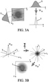
- this processing step 200 advantageously comprises the implementation of a Radon transformation as illustrated in the figures 3A and 3B .
- the processing step can also comprise a double Fourier transform (temporal, then spatial).
- a one-dimensional Fourier transformation of the measurement signal S is implemented, which provides the associated slice of profile T as illustrated in Fig. Figure 3A . It is therefore clearly understood that the quality of the sampling of the measurement signal S is important to guarantee preservation of the information during the Fourier transformation.
- a two-dimensional profile P is determined from the plurality of slices of profile T associated with the plurality of measurement signals S.
- the two-dimensional profile P is determined by registration in a Fourier space of the plurality of profile slices.
- Each slice of profile T is thus readjusted in Fourier space according to the direction of propagation ⁇ of the non-focused acoustic wave which was associated with the measurement signal S associated with the slice of profile T.
- the two-dimensional profile P has been obtained, it is then possible to determine one or more representative value(s) of a light intensity I in the observation zone 3 by an inverse two-dimensional Fourier transformation of the two-dimensional profile P, as also illustrated in the Figure 3B .
- the slices of profile T can be completed to determine the two-dimensional profile P.
- the figure 4 illustrates a result obtained during the implementation of an exemplary embodiment of the invention.
- the graph in this figure illustrates the light intensity as a function of the position along an axis crossing the observation zone.
- the medium imaged is an agar gel mixed with 10% intralipid.
- Such a gel is very diffusing so that beyond a millimeter, it is impossible to observe what is inside.
- An absorbent object, or locally more or less diffusing than the gel, is placed in the diffusing gel.
- a sheath of black electrical wire approximately 1 mm in diameter and 5 millimeters long can be placed substantially in the middle of the gel to obtain the example of the figure 4 .
- the graph of the figure 4 makes it possible to compare the light intensity as a function of the position obtained by an implementation of the invention (in dotted lines) with the light intensity as a function of the position obtained by an implementation of a known method such as described in the introduction to the present description, in which the observation zone is scanned using focused ultrasonic waves (in solid lines).
- each measurement operation is repeated 1000 times to obtain an averaged measurement signal.
- the light intensity values are obtained by performing a series of ultrasonic wave emissions focused whose focal spots are offset from each other by 0.2 mm so as to obtain an image of the light intensity in the observation zone 3 with 100 columns.
- the signal-to-noise ratio (SNR) of the light intensity as a function of position obtained by the implementation of the invention is much better than the signal-to-noise ratio of the light intensity as a function of the position obtained by the implementation of said known method.
Landscapes
- Physics & Mathematics (AREA)
- Health & Medical Sciences (AREA)
- Life Sciences & Earth Sciences (AREA)
- General Health & Medical Sciences (AREA)
- Pathology (AREA)
- General Physics & Mathematics (AREA)
- Immunology (AREA)
- Biochemistry (AREA)
- Analytical Chemistry (AREA)
- Chemical & Material Sciences (AREA)
- Nonlinear Science (AREA)
- Engineering & Computer Science (AREA)
- Heart & Thoracic Surgery (AREA)
- Surgery (AREA)
- Public Health (AREA)
- Veterinary Medicine (AREA)
- Molecular Biology (AREA)
- Medical Informatics (AREA)
- Animal Behavior & Ethology (AREA)
- Biomedical Technology (AREA)
- Biophysics (AREA)
- Acoustics & Sound (AREA)
- Optics & Photonics (AREA)
- Investigating Or Analysing Materials By Optical Means (AREA)
- Investigating Or Analyzing Materials By The Use Of Ultrasonic Waves (AREA)
Claims (15)
- Akustooptisches Abbildungsverfahren zum Abbilden eines Beobachtungsbereichs (3) eines Mediums (2), wobei das Verfahren folgende Schritte aufweist- einen Erfassungsschritt (100), bei dem eine Vielzahl von Messsignalen (S) erfasst wird, die einer Vielzahl von nicht fokussierten akustischen Wellen zugeordnet sind, die sich in nicht kollinearen Ausbreitungsrichtungen (θ) ausbreiten, wobei der Erfassungsschritt eine Vielzahl von Messvorgängen (150) aufweist, so dass während jedes Messvorgangs (150) der Vielzahl von Messvorgängen (150):- in dem Beobachtungsbereich (3) eine nicht fokussierte akustische Welle erzeugt wird, die sich entlang einer Ausbreitungsrichtung (θ) ausbreitet;- in den Beobachtungsbereich (3) eine einfallende Lichtwelle ausgesendet wird, um eine markierte Lichtwelle zu erzeugen, die mindestens eine akustooptische Komponente aufweist, deren Frequenz durch die nicht fokussierte akustische Welle verschoben wird;- ein Messsignal (S) erfasst wird, das der nicht fokussierten akustischen Welle zugeordnet ist und Informationen über die markierte Lichtwelle enthält; und- einen Bearbeitungsschritt (200), in dem mindestens ein Wert, der für eine Lichtintensität (I) in dem Beobachtungsbereich (3) repräsentativ ist, aus der Vielzahl von Messsignalen (S) bestimmt wird, wobei der Bearbeitungsschritt folgende Schritte aufweist:- Bestimmen (210) einer Vielzahl von Teilprofilen (T), wobei jedes Teilprofil eine Funktion einer eindimensionalen Fouriertransformation eines zugehörigen Messsignals ist, das für eine nicht fokussierte akustische Welle erfasst wurde, die sich gemäß einer zugehörigen Ausbreitungsrichtung ausbreitet;- Bestimmen eines zweidimensionalen Spektrums (P) aus der Vielzahl von Teilprofilen (T), und- Bestimmen des mindestens einen repräsentativen Werts der Lichtintensität (I) im Beobachtungsbereich (3), wobei der repräsentative Wert eine Funktion einer inversen zweidimensionalen Fouriertransformation des zweidimensionalen Spektrums (P) ist.
- Verfahren nach Anspruch 1, wobei die nicht fokussierte akustische Welle eine ebene akustische Welle ist.
- Verfahren nach Anspruch 1, wobei die nicht fokussierte akustische Welle eine divergente akustische Welle ist.
- Verfahren nach einem der Ansprüche 1 bis 3, wobei die Ausbreitungsrichtungen (θ) der mehreren nicht fokussierten akustischen Wellen einen Winkelsektor mit einem Winkel von mehr als 10 Grad abdecken.
- Verfahren nach einem der Ansprüche 1 bis 4, wobei die Ausbreitungsrichtungen (θ) der mehreren nicht fokussierten akustischen Wellen durch einen Winkelabstand von mehr als 0,1 Grad, vorzugsweise mehr als 0,5 Grad, voneinander getrennt sind.
- Verfahren nach einem der Ansprüche 1 bis 5, wobei die Ausbreitungsrichtungen (θ) der mehreren nicht fokussierten akustischen Wellen durch einen Winkelabstand von weniger als 45 Grad, vorzugsweise weniger als 20 Grad, voneinander getrennt sind.
- Verfahren nach einem der Ansprüche 1 bis 6, wobei jedes Messsignal (S), das einer nicht fokussierten akustischen Welle zugeordnet ist, eine Zeitreihe von Lichtintensitätswerten aufweist, die Informationen über die akustooptische Komponente der markierten Lichtwelle enthält, die durch die nicht fokussierte akustische Welle in der Frequenz verschoben wird.
- Verfahren nach einem der Ansprüche 1 bis 7, wobei jedes Messsignal (S), das einer nicht fokussierten akustischen Welle zugeordnet ist, mit einer Frequenz von mehr als 2 Megahertz, vorzugsweise mehr als zehn Megahertz, abgetastet wird.
- Verfahren nach einem der Ansprüche 1 bis 8, wobei der Bearbeitungsschritt (200) die Durchführung einer inversen Radon-Transformation aufweist.
- Verfahren nach einem der Ansprüche 1 bis 9, wobei der Bearbeitungsschritt (200) die Implementierung eines Spurbildungsalgorithmus aufweist.
- Verfahren nach einem der Ansprüche 1 bis 10, wobei der Bearbeitungsschritt (200) die Implementierung eines Algorithmus zur Rückprojektion oder gefilterten Rückprojektion aufweist.
- Verfahren nach einem der Ansprüche 1 bis 11, bei dem das zweidimensionale Spektrum (P) durch Neuberechnung der mehreren Teilprofile (T) in einem Fourierraum bestimmt wird, wobei jedes Teilprofil in Abhängigkeit von der Ausbreitungsrichtung (θ) einer nicht fokussierten akustischen Welle, die mit dem dem Teilprofil (T) zugeordneten Messsignal (S) zugeordnet ist, neu berechnet wird.
- Verfahren nach einem der Ansprüche 1 bis 12, wobei ein Messvorgang (150) n-mal wiederholt wird, um n Messsignale (S) zu erfassen, die einer Ausbreitungsrichtung (θ) einer nicht fokussierten akustischen Welle zugeordnet sind, und wobei die n Messsignale insgesamt gemittelt werden, um ein der nicht fokussierten akustischen Welle zugeordnetes Messsignal zu bestimmen, das für den Bearbeitungsschritt (200) verwendet wird.
- Verfahren nach einem der Ansprüche 1 bis 13, wobei der Messvorgang (150) für eine n-te Anzahl von Malen größer oder gleich 1 wiederholt wird.
- System (1) zur akustooptischen Abbildung eines Beobachtungsbereichs (3) eines Mediums (2), wobei das System folgende Merkmale aufweist- eine Erfassungsvorrichtung (11) zur Erfassung einer Vielzahl von Messsignalen (S), die einer Vielzahl von nicht fokussierten akustischen Wellen zugeordnet sind, die sich in nicht kollinearen Ausbreitungsrichtungen (θ) ausbreiten, wobei die Erfassungsvorrichtung folgende Merkmale aufweist:- eine Anordnung von Wandlern (4), um in dem Beobachtungsbereich (3) eine Vielzahl von nicht fokussierten akustischen Wellen zu erzeugen, die sich in nicht kollinearen Ausbreitungsrichtungen (θ) ausbreiten,- eine Lichtemissionsvorrichtung (8), um in den Beobachtungsbereich (3) mindestens eine einfallende Lichtwelle auszusenden, um eine Vielzahl von markierten Lichtwellen zu erzeugen, von denen jede mindestens eine akustooptische Komponente aufweist, die jeweils durch eine nicht fokussierte akustische Welle der Vielzahl von nicht fokussierten akustischen Wellen in der Frequenz verschoben ist,- einen Detektor (9) zum Erfassen einer Vielzahl von Messsignalen (S), die der Vielzahl von nicht fokussierten akustischen Wellen zugeordnet sind und jeweils repräsentativ für jede markierte Lichtwelle der Vielzahl von markierten Lichtwellen sind; und- eine Bearbeitungsvorrichtung (12), die so konfiguriert ist, dass sie mindestens einen Wert, der für eine Lichtintensität (I) in dem Beobachtungsbereich (3) repräsentativ ist, aus der Vielzahl von Messsignalen (S) bestimmt, die von der Erfassungsvorrichtung (11) erfasst werden, wobei die Bearbeitungsvorrichtung Mittel umfasst, die konfiguriert sind zum:- Bestimmen (210) einer Vielzahl von Teilprofilen (T), wobei jedes Teilprofil eine Funktion einer eindimensionalen Fourier-Transformation eines zugehörigen Messsignals ist, das für eine nicht fokussierte akustische Welle erfasst wurde, die sich entlang einer zugehörigen Ausbreitungsrichtung ausbreitet,- Bestimmen mindestens eines zweidimensionalen Spektrums (P) aus der Vielzahl von Teilprofilen (T), und- Bestimmen des mindestens einen repräsentativen Werts der Lichtintensität (I) im Beobachtungsbereich (3), wobei der repräsentative Wert eine Funktion einer inversen zweidimensionalen Fourier-Transformation des zweidimensionalen Spektrums (P) ist.
Applications Claiming Priority (1)
| Application Number | Priority Date | Filing Date | Title |
|---|---|---|---|
| PCT/FR2015/051448 WO2016193554A1 (fr) | 2015-06-02 | 2015-06-02 | Procedes et systemes d'imagerie acousto-optique |
Publications (2)
| Publication Number | Publication Date |
|---|---|
| EP3304043A1 EP3304043A1 (de) | 2018-04-11 |
| EP3304043B1 true EP3304043B1 (de) | 2022-03-09 |
Family
ID=53434372
Family Applications (1)
| Application Number | Title | Priority Date | Filing Date |
|---|---|---|---|
| EP15730211.8A Active EP3304043B1 (de) | 2015-06-02 | 2015-06-02 | Verfahren und systeme zum akusto-optischen abbilden |
Country Status (4)
| Country | Link |
|---|---|
| US (1) | US20180217051A1 (de) |
| EP (1) | EP3304043B1 (de) |
| JP (1) | JP6678189B2 (de) |
| WO (1) | WO2016193554A1 (de) |
Families Citing this family (6)
| Publication number | Priority date | Publication date | Assignee | Title |
|---|---|---|---|---|
| US10016137B1 (en) | 2017-11-22 | 2018-07-10 | Hi Llc | System and method for simultaneously detecting phase modulated optical signals |
| US10335036B2 (en) | 2017-11-22 | 2019-07-02 | Hi Llc | Pulsed ultrasound modulated optical tomography using lock-in camera |
| US10368752B1 (en) | 2018-03-08 | 2019-08-06 | Hi Llc | Devices and methods to convert conventional imagers into lock-in cameras |
| FR3078807B1 (fr) | 2018-03-09 | 2020-03-20 | Centre National De La Recherche Scientifique - Cnrs - | Procedes et systemes d'imagerie acousto-optique |
| US11206985B2 (en) | 2018-04-13 | 2021-12-28 | Hi Llc | Non-invasive optical detection systems and methods in highly scattering medium |
| US11857316B2 (en) | 2018-05-07 | 2024-01-02 | Hi Llc | Non-invasive optical detection system and method |
Family Cites Families (28)
| Publication number | Priority date | Publication date | Assignee | Title |
|---|---|---|---|---|
| US4634230A (en) * | 1984-02-03 | 1987-01-06 | The United States Of America As Represented By The Secretary Of The Navy | Multi dimensional instantaneous optical signal processor |
| FR2615619B1 (fr) * | 1987-05-21 | 1991-07-19 | Commissariat Energie Atomique | Procede et dispositif d'imagerie tridimentionnelle a partir de mesures bidimensionnelles de l'attenuation d'un rayonnement |
| FR2617602B1 (fr) * | 1987-07-03 | 1989-10-20 | Thomson Csf | Procede et systeme d'imagerie par transillumination a marquage en frequence des photons |
| US5053958A (en) * | 1988-06-06 | 1991-10-01 | General Electric Company | Method to reduce image reconstruction time in limited-angle ct systems including using initial reconstruction valves for measured projection data during each iteration |
| FR2641099B1 (de) * | 1988-12-22 | 1991-02-22 | Gen Electric Cgr | |
| FR2648304B1 (fr) * | 1989-06-12 | 1991-08-30 | Commissariat Energie Atomique | Procede de determination d'un espace a partir d'un espace discret connu pour la reconstruction d'images bi ou tridimensionnelles, dispositif de mise en oeuvre et application du procede |
| FR2696027B1 (fr) * | 1992-09-18 | 1994-10-28 | Commissariat Energie Atomique | Procédé de reconstruction d'images tridimensionnelles d'une région d'intérêt d'un objet, et installation appropriée. |
| FR2736454B1 (fr) * | 1995-07-03 | 1997-08-08 | Commissariat Energie Atomique | Procede de reconstruction d'images tridimensionnelles sur un objet mobile ou deformable |
| US5719399A (en) * | 1995-12-18 | 1998-02-17 | The Research Foundation Of City College Of New York | Imaging and characterization of tissue based upon the preservation of polarized light transmitted therethrough |
| US5941825A (en) * | 1996-10-21 | 1999-08-24 | Philipp Lang | Measurement of body fat using ultrasound methods and devices |
| US6041248A (en) * | 1997-05-07 | 2000-03-21 | The Texas A&M University System | Method and apparatus for frequency encoded ultrasound-modulated optical tomography of dense turbid media |
| US6585649B1 (en) * | 1998-05-02 | 2003-07-01 | John D. Mendlein | Methods and devices for improving ultrasonic measurements using multiple angle interrogation |
| US6013031A (en) * | 1998-03-09 | 2000-01-11 | Mendlein; John D. | Methods and devices for improving ultrasonic measurements using anatomic landmarks and soft tissue correction |
| US8126524B2 (en) * | 2003-09-12 | 2012-02-28 | Or-Nim Medical Ltd. | Method and apparatus for noninvasively monitoring parameters of a region of interest in a human body |
| US20060061770A1 (en) * | 2004-09-22 | 2006-03-23 | The Regents Of The University Of California | Heterodyning time resolution boosting method and system |
| DK1863387T3 (da) * | 2005-03-16 | 2013-09-16 | Or Nim Medical Ltd | Ikke-invasive målinger i en menneskekrop |
| EP1940286A1 (de) * | 2005-09-29 | 2008-07-09 | General Hospital Corporation | Verfahren und gerät für ein verfahren zur betrachtung und auswertung einer oder mehrerer biologischen proben mit progressiv zunehmender auflösung |
| US7796270B2 (en) * | 2006-01-10 | 2010-09-14 | The General Hospital Corporation | Systems and methods for generating data based on one or more spectrally-encoded endoscopy techniques |
| US7541602B2 (en) * | 2007-06-04 | 2009-06-02 | Or-Nim Medical Ltd. | System and method for noninvasively monitoring conditions of a subject |
| JP5284129B2 (ja) * | 2008-02-06 | 2013-09-11 | キヤノン株式会社 | イメージング装置、及び解析方法 |
| EP2110076A1 (de) * | 2008-02-19 | 2009-10-21 | Helmholtz Zentrum München Deutsches Forschungszentrum für Gesundheit und Umwelt (GmbH) | Verfahren und Vorrichtung zur Nahfeld-Doppelwellen-Modalitätsbildgebung |
| JP5156934B2 (ja) * | 2008-03-07 | 2013-03-06 | 学校法人日本大学 | 音響測定装置 |
| JP5183381B2 (ja) * | 2008-09-16 | 2013-04-17 | キヤノン株式会社 | 測定装置及び測定方法 |
| US10092271B2 (en) * | 2011-04-13 | 2018-10-09 | Cornell University | Ultrasound transducer probe and methods |
| JP5840181B2 (ja) * | 2012-08-17 | 2016-01-06 | 富士フイルム株式会社 | 光音響画像生成装置及び方法 |
| JP6173159B2 (ja) * | 2013-10-04 | 2017-08-02 | キヤノン株式会社 | 光音響装置 |
| US10157483B2 (en) * | 2013-12-19 | 2018-12-18 | Board Of Regents, The University Of Texas System | Backprojection approach for photoacoustic image reconstruction |
| DE102014113433B4 (de) * | 2014-09-17 | 2016-07-14 | Carl Zeiss Ag | Vorrichtung und Verfahren zur dreidimensionalen Abbildung eines Objekts |
-
2015
- 2015-06-02 EP EP15730211.8A patent/EP3304043B1/de active Active
- 2015-06-02 WO PCT/FR2015/051448 patent/WO2016193554A1/fr not_active Ceased
- 2015-06-02 US US15/579,400 patent/US20180217051A1/en not_active Abandoned
- 2015-06-02 JP JP2017562735A patent/JP6678189B2/ja active Active
Non-Patent Citations (1)
| Title |
|---|
| None * |
Also Published As
| Publication number | Publication date |
|---|---|
| EP3304043A1 (de) | 2018-04-11 |
| JP6678189B2 (ja) | 2020-04-08 |
| JP2018517907A (ja) | 2018-07-05 |
| WO2016193554A1 (fr) | 2016-12-08 |
| US20180217051A1 (en) | 2018-08-02 |
Similar Documents
| Publication | Publication Date | Title |
|---|---|---|
| EP3304043B1 (de) | Verfahren und systeme zum akusto-optischen abbilden | |
| EP2309249B1 (de) | Vorrichtung und Verfahren zur gestreuten Erregung in der Bildgebung | |
| WO1995026160A1 (fr) | Procede et dispositif d'evaluation et de caracterisation des proprietes des os | |
| EP3488505B1 (de) | Verfahren und system zur akustischen resonanzspektroskopie | |
| CN115201115A (zh) | 基于结构光探测的光声成像装置与方法 | |
| WO2004085978A2 (fr) | Procede et installation d'imagerie acousto-optique | |
| EP3555659B1 (de) | Verfahren zur erfassung von ultraschallprüfsignalen sowie entsprechendes computerprogramm und ultraschallprüfvorrichtung | |
| EP3311138B1 (de) | Bestimmung des absorptions- und streukoeffizienten mittels eines kalibrierten optischen reflexionssignals | |
| WO2020240131A1 (fr) | Systeme de mesure acoustique picoseconde a double faisceaux sondes | |
| EP3761857B1 (de) | Akustisch-optische bildgebungsverfahren und systeme | |
| FR2849215A1 (fr) | Systeme de microscopie laser confocale parallele basee sur la technologie vcsel | |
| FR3075960A1 (fr) | Dispositif de mesure d'un rayonnement retrodiffuse par un echantillon et procede de mesure utilisant un tel dispositif. | |
| FR3065078A1 (fr) | Procede et dispositif de sondage ultrasonore par focalisation adaptative au moyen d'un objet solide reverberant | |
| FR2512339A1 (fr) | Appareil de diagnostic a ultrasons | |
| Prebeck et al. | Comparison of Bulk Piezoelectric and Opto-Mechanical Micromachined Detectors for Optoacoustic and Ultrasound Sensing | |
| FR3118197A1 (fr) | Lidar cohérent à modulation de fréquence amélioré | |
| CA2184510C (fr) | Procede et dispositif d'evaluation et de caracterisation des proprietes des os | |
| WO2025125247A1 (fr) | Dispositif et procede d'imagerie par ultrasons a emission et reception en continu | |
| Ephrat et al. | Measurement of photoacoustic detector sensitivity distribution by robotic source placement | |
| JP2023178763A (ja) | 光音響波発生装置、光音響波発生方法及び組成推定方法 | |
| FR2784194A1 (fr) | Dispositif d'imagerie utilisant un ensemble de microlasers et procede de fabrication de ceux-ci | |
| FR2611057A1 (fr) | Dispositif acousto-optique utilisant un materiau elastomere systeme de modulation optique et systeme de velocimetrie laser utilisant ce dispositif | |
| Sakadžić et al. | Toward very high resolution imaging in ultrasound-modulated optical tomography of biological tissues | |
| Kunihiro et al. | Experimental study of pulsed ultrasono-optical tomography | |
| FR3048514A1 (fr) | Microscopie optique non-lineaire quantitative |
Legal Events
| Date | Code | Title | Description |
|---|---|---|---|
| STAA | Information on the status of an ep patent application or granted ep patent |
Free format text: STATUS: THE INTERNATIONAL PUBLICATION HAS BEEN MADE |
|
| PUAI | Public reference made under article 153(3) epc to a published international application that has entered the european phase |
Free format text: ORIGINAL CODE: 0009012 |
|
| STAA | Information on the status of an ep patent application or granted ep patent |
Free format text: STATUS: REQUEST FOR EXAMINATION WAS MADE |
|
| 17P | Request for examination filed |
Effective date: 20171130 |
|
| AK | Designated contracting states |
Kind code of ref document: A1 Designated state(s): AL AT BE BG CH CY CZ DE DK EE ES FI FR GB GR HR HU IE IS IT LI LT LU LV MC MK MT NL NO PL PT RO RS SE SI SK SM TR |
|
| AX | Request for extension of the european patent |
Extension state: BA ME |
|
| DAV | Request for validation of the european patent (deleted) | ||
| DAX | Request for extension of the european patent (deleted) | ||
| STAA | Information on the status of an ep patent application or granted ep patent |
Free format text: STATUS: EXAMINATION IS IN PROGRESS |
|
| 17Q | First examination report despatched |
Effective date: 20190807 |
|
| GRAP | Despatch of communication of intention to grant a patent |
Free format text: ORIGINAL CODE: EPIDOSNIGR1 |
|
| STAA | Information on the status of an ep patent application or granted ep patent |
Free format text: STATUS: GRANT OF PATENT IS INTENDED |
|
| INTG | Intention to grant announced |
Effective date: 20211019 |
|
| RIN1 | Information on inventor provided before grant (corrected) |
Inventor name: GENNISSON, JEAN-LUC Inventor name: LAUDEREAU, JEAN-BAPTISTE Inventor name: TANTER, MICKAEL Inventor name: RAMAZ, FRANCOIS |
|
| GRAS | Grant fee paid |
Free format text: ORIGINAL CODE: EPIDOSNIGR3 |
|
| GRAA | (expected) grant |
Free format text: ORIGINAL CODE: 0009210 |
|
| STAA | Information on the status of an ep patent application or granted ep patent |
Free format text: STATUS: THE PATENT HAS BEEN GRANTED |
|
| AK | Designated contracting states |
Kind code of ref document: B1 Designated state(s): AL AT BE BG CH CY CZ DE DK EE ES FI FR GB GR HR HU IE IS IT LI LT LU LV MC MK MT NL NO PL PT RO RS SE SI SK SM TR |
|
| REG | Reference to a national code |
Ref country code: GB Ref legal event code: FG4D Free format text: NOT ENGLISH |
|
| REG | Reference to a national code |
Ref country code: CH Ref legal event code: EP Ref country code: AT Ref legal event code: REF Ref document number: 1474564 Country of ref document: AT Kind code of ref document: T Effective date: 20220315 |
|
| REG | Reference to a national code |
Ref country code: IE Ref legal event code: FG4D Free format text: LANGUAGE OF EP DOCUMENT: FRENCH |
|
| REG | Reference to a national code |
Ref country code: DE Ref legal event code: R096 Ref document number: 602015077392 Country of ref document: DE |
|
| REG | Reference to a national code |
Ref country code: NL Ref legal event code: FP |
|
| REG | Reference to a national code |
Ref country code: LT Ref legal event code: MG9D |
|
| PG25 | Lapsed in a contracting state [announced via postgrant information from national office to epo] |
Ref country code: SE Free format text: LAPSE BECAUSE OF FAILURE TO SUBMIT A TRANSLATION OF THE DESCRIPTION OR TO PAY THE FEE WITHIN THE PRESCRIBED TIME-LIMIT Effective date: 20220309 Ref country code: RS Free format text: LAPSE BECAUSE OF FAILURE TO SUBMIT A TRANSLATION OF THE DESCRIPTION OR TO PAY THE FEE WITHIN THE PRESCRIBED TIME-LIMIT Effective date: 20220309 Ref country code: NO Free format text: LAPSE BECAUSE OF FAILURE TO SUBMIT A TRANSLATION OF THE DESCRIPTION OR TO PAY THE FEE WITHIN THE PRESCRIBED TIME-LIMIT Effective date: 20220609 Ref country code: LT Free format text: LAPSE BECAUSE OF FAILURE TO SUBMIT A TRANSLATION OF THE DESCRIPTION OR TO PAY THE FEE WITHIN THE PRESCRIBED TIME-LIMIT Effective date: 20220309 Ref country code: HR Free format text: LAPSE BECAUSE OF FAILURE TO SUBMIT A TRANSLATION OF THE DESCRIPTION OR TO PAY THE FEE WITHIN THE PRESCRIBED TIME-LIMIT Effective date: 20220309 Ref country code: BG Free format text: LAPSE BECAUSE OF FAILURE TO SUBMIT A TRANSLATION OF THE DESCRIPTION OR TO PAY THE FEE WITHIN THE PRESCRIBED TIME-LIMIT Effective date: 20220609 |
|
| REG | Reference to a national code |
Ref country code: AT Ref legal event code: MK05 Ref document number: 1474564 Country of ref document: AT Kind code of ref document: T Effective date: 20220309 |
|
| PG25 | Lapsed in a contracting state [announced via postgrant information from national office to epo] |
Ref country code: LV Free format text: LAPSE BECAUSE OF FAILURE TO SUBMIT A TRANSLATION OF THE DESCRIPTION OR TO PAY THE FEE WITHIN THE PRESCRIBED TIME-LIMIT Effective date: 20220309 Ref country code: GR Free format text: LAPSE BECAUSE OF FAILURE TO SUBMIT A TRANSLATION OF THE DESCRIPTION OR TO PAY THE FEE WITHIN THE PRESCRIBED TIME-LIMIT Effective date: 20220610 Ref country code: FI Free format text: LAPSE BECAUSE OF FAILURE TO SUBMIT A TRANSLATION OF THE DESCRIPTION OR TO PAY THE FEE WITHIN THE PRESCRIBED TIME-LIMIT Effective date: 20220309 |
|
| PG25 | Lapsed in a contracting state [announced via postgrant information from national office to epo] |
Ref country code: SM Free format text: LAPSE BECAUSE OF FAILURE TO SUBMIT A TRANSLATION OF THE DESCRIPTION OR TO PAY THE FEE WITHIN THE PRESCRIBED TIME-LIMIT Effective date: 20220309 Ref country code: SK Free format text: LAPSE BECAUSE OF FAILURE TO SUBMIT A TRANSLATION OF THE DESCRIPTION OR TO PAY THE FEE WITHIN THE PRESCRIBED TIME-LIMIT Effective date: 20220309 Ref country code: RO Free format text: LAPSE BECAUSE OF FAILURE TO SUBMIT A TRANSLATION OF THE DESCRIPTION OR TO PAY THE FEE WITHIN THE PRESCRIBED TIME-LIMIT Effective date: 20220309 Ref country code: PT Free format text: LAPSE BECAUSE OF FAILURE TO SUBMIT A TRANSLATION OF THE DESCRIPTION OR TO PAY THE FEE WITHIN THE PRESCRIBED TIME-LIMIT Effective date: 20220711 Ref country code: ES Free format text: LAPSE BECAUSE OF FAILURE TO SUBMIT A TRANSLATION OF THE DESCRIPTION OR TO PAY THE FEE WITHIN THE PRESCRIBED TIME-LIMIT Effective date: 20220309 Ref country code: EE Free format text: LAPSE BECAUSE OF FAILURE TO SUBMIT A TRANSLATION OF THE DESCRIPTION OR TO PAY THE FEE WITHIN THE PRESCRIBED TIME-LIMIT Effective date: 20220309 Ref country code: CZ Free format text: LAPSE BECAUSE OF FAILURE TO SUBMIT A TRANSLATION OF THE DESCRIPTION OR TO PAY THE FEE WITHIN THE PRESCRIBED TIME-LIMIT Effective date: 20220309 Ref country code: AT Free format text: LAPSE BECAUSE OF FAILURE TO SUBMIT A TRANSLATION OF THE DESCRIPTION OR TO PAY THE FEE WITHIN THE PRESCRIBED TIME-LIMIT Effective date: 20220309 |
|
| PG25 | Lapsed in a contracting state [announced via postgrant information from national office to epo] |
Ref country code: PL Free format text: LAPSE BECAUSE OF FAILURE TO SUBMIT A TRANSLATION OF THE DESCRIPTION OR TO PAY THE FEE WITHIN THE PRESCRIBED TIME-LIMIT Effective date: 20220309 Ref country code: IS Free format text: LAPSE BECAUSE OF FAILURE TO SUBMIT A TRANSLATION OF THE DESCRIPTION OR TO PAY THE FEE WITHIN THE PRESCRIBED TIME-LIMIT Effective date: 20220709 Ref country code: AL Free format text: LAPSE BECAUSE OF FAILURE TO SUBMIT A TRANSLATION OF THE DESCRIPTION OR TO PAY THE FEE WITHIN THE PRESCRIBED TIME-LIMIT Effective date: 20220309 |
|
| REG | Reference to a national code |
Ref country code: DE Ref legal event code: R097 Ref document number: 602015077392 Country of ref document: DE |
|
| PLBE | No opposition filed within time limit |
Free format text: ORIGINAL CODE: 0009261 |
|
| STAA | Information on the status of an ep patent application or granted ep patent |
Free format text: STATUS: NO OPPOSITION FILED WITHIN TIME LIMIT |
|
| PG25 | Lapsed in a contracting state [announced via postgrant information from national office to epo] |
Ref country code: MC Free format text: LAPSE BECAUSE OF FAILURE TO SUBMIT A TRANSLATION OF THE DESCRIPTION OR TO PAY THE FEE WITHIN THE PRESCRIBED TIME-LIMIT Effective date: 20220309 Ref country code: DK Free format text: LAPSE BECAUSE OF FAILURE TO SUBMIT A TRANSLATION OF THE DESCRIPTION OR TO PAY THE FEE WITHIN THE PRESCRIBED TIME-LIMIT Effective date: 20220309 |
|
| REG | Reference to a national code |
Ref country code: CH Ref legal event code: PL |
|
| 26N | No opposition filed |
Effective date: 20221212 |
|
| REG | Reference to a national code |
Ref country code: BE Ref legal event code: MM Effective date: 20220630 |
|
| PG25 | Lapsed in a contracting state [announced via postgrant information from national office to epo] |
Ref country code: SI Free format text: LAPSE BECAUSE OF FAILURE TO SUBMIT A TRANSLATION OF THE DESCRIPTION OR TO PAY THE FEE WITHIN THE PRESCRIBED TIME-LIMIT Effective date: 20220309 |
|
| PG25 | Lapsed in a contracting state [announced via postgrant information from national office to epo] |
Ref country code: LU Free format text: LAPSE BECAUSE OF NON-PAYMENT OF DUE FEES Effective date: 20220602 Ref country code: LI Free format text: LAPSE BECAUSE OF NON-PAYMENT OF DUE FEES Effective date: 20220630 Ref country code: IE Free format text: LAPSE BECAUSE OF NON-PAYMENT OF DUE FEES Effective date: 20220602 Ref country code: CH Free format text: LAPSE BECAUSE OF NON-PAYMENT OF DUE FEES Effective date: 20220630 |
|
| PG25 | Lapsed in a contracting state [announced via postgrant information from national office to epo] |
Ref country code: BE Free format text: LAPSE BECAUSE OF NON-PAYMENT OF DUE FEES Effective date: 20220630 |
|
| PG25 | Lapsed in a contracting state [announced via postgrant information from national office to epo] |
Ref country code: HU Free format text: LAPSE BECAUSE OF FAILURE TO SUBMIT A TRANSLATION OF THE DESCRIPTION OR TO PAY THE FEE WITHIN THE PRESCRIBED TIME-LIMIT; INVALID AB INITIO Effective date: 20150602 |
|
| PG25 | Lapsed in a contracting state [announced via postgrant information from national office to epo] |
Ref country code: MK Free format text: LAPSE BECAUSE OF FAILURE TO SUBMIT A TRANSLATION OF THE DESCRIPTION OR TO PAY THE FEE WITHIN THE PRESCRIBED TIME-LIMIT Effective date: 20220309 Ref country code: CY Free format text: LAPSE BECAUSE OF FAILURE TO SUBMIT A TRANSLATION OF THE DESCRIPTION OR TO PAY THE FEE WITHIN THE PRESCRIBED TIME-LIMIT Effective date: 20220309 |
|
| PG25 | Lapsed in a contracting state [announced via postgrant information from national office to epo] |
Ref country code: TR Free format text: LAPSE BECAUSE OF FAILURE TO SUBMIT A TRANSLATION OF THE DESCRIPTION OR TO PAY THE FEE WITHIN THE PRESCRIBED TIME-LIMIT Effective date: 20220309 |
|
| PG25 | Lapsed in a contracting state [announced via postgrant information from national office to epo] |
Ref country code: MT Free format text: LAPSE BECAUSE OF FAILURE TO SUBMIT A TRANSLATION OF THE DESCRIPTION OR TO PAY THE FEE WITHIN THE PRESCRIBED TIME-LIMIT Effective date: 20220309 |
|
| PGFP | Annual fee paid to national office [announced via postgrant information from national office to epo] |
Ref country code: GB Payment date: 20250626 Year of fee payment: 11 |
|
| PGFP | Annual fee paid to national office [announced via postgrant information from national office to epo] |
Ref country code: NL Payment date: 20250627 Year of fee payment: 11 |
|
| PGFP | Annual fee paid to national office [announced via postgrant information from national office to epo] |
Ref country code: FR Payment date: 20250626 Year of fee payment: 11 |
|
| PGFP | Annual fee paid to national office [announced via postgrant information from national office to epo] |
Ref country code: DE Payment date: 20250725 Year of fee payment: 11 |
|
| PGFP | Annual fee paid to national office [announced via postgrant information from national office to epo] |
Ref country code: IT Payment date: 20250626 Year of fee payment: 11 |