EP3304655B1 - Verriegelungssystem für einen ladestecker - Google Patents
Verriegelungssystem für einen ladestecker Download PDFInfo
- Publication number
- EP3304655B1 EP3304655B1 EP16727142.8A EP16727142A EP3304655B1 EP 3304655 B1 EP3304655 B1 EP 3304655B1 EP 16727142 A EP16727142 A EP 16727142A EP 3304655 B1 EP3304655 B1 EP 3304655B1
- Authority
- EP
- European Patent Office
- Prior art keywords
- locking
- charging plug
- adapter
- drive
- plug receptacle
- Prior art date
- Legal status (The legal status is an assumption and is not a legal conclusion. Google has not performed a legal analysis and makes no representation as to the accuracy of the status listed.)
- Not-in-force
Links
Images


Classifications
-
- H—ELECTRICITY
- H01—ELECTRIC ELEMENTS
- H01R—ELECTRICALLY-CONDUCTIVE CONNECTIONS; STRUCTURAL ASSOCIATIONS OF A PLURALITY OF MUTUALLY-INSULATED ELECTRICAL CONNECTING ELEMENTS; COUPLING DEVICES; CURRENT COLLECTORS
- H01R13/00—Details of coupling devices of the kinds covered by groups H01R12/70 or H01R24/00 - H01R33/00
- H01R13/62—Means for facilitating engagement or disengagement of coupling parts or for holding them in engagement
- H01R13/639—Additional means for holding or locking coupling parts together, after engagement, e.g. separate keylock, retainer strap
- H01R13/6397—Additional means for holding or locking coupling parts together, after engagement, e.g. separate keylock, retainer strap with means for preventing unauthorised use
-
- B—PERFORMING OPERATIONS; TRANSPORTING
- B60—VEHICLES IN GENERAL
- B60L—PROPULSION OF ELECTRICALLY-PROPELLED VEHICLES; SUPPLYING ELECTRIC POWER FOR AUXILIARY EQUIPMENT OF ELECTRICALLY-PROPELLED VEHICLES; ELECTRODYNAMIC BRAKE SYSTEMS FOR VEHICLES IN GENERAL; MAGNETIC SUSPENSION OR LEVITATION FOR VEHICLES; MONITORING OPERATING VARIABLES OF ELECTRICALLY-PROPELLED VEHICLES; ELECTRIC SAFETY DEVICES FOR ELECTRICALLY-PROPELLED VEHICLES
- B60L53/00—Methods of charging batteries, specially adapted for electric vehicles; Charging stations or on-board charging equipment therefor; Exchange of energy storage elements in electric vehicles
- B60L53/10—Methods of charging batteries, specially adapted for electric vehicles; Charging stations or on-board charging equipment therefor; Exchange of energy storage elements in electric vehicles characterised by the energy transfer between the charging station and the vehicle
- B60L53/14—Conductive energy transfer
- B60L53/16—Connectors, e.g. plugs or sockets, specially adapted for charging electric vehicles
-
- H—ELECTRICITY
- H01—ELECTRIC ELEMENTS
- H01R—ELECTRICALLY-CONDUCTIVE CONNECTIONS; STRUCTURAL ASSOCIATIONS OF A PLURALITY OF MUTUALLY-INSULATED ELECTRICAL CONNECTING ELEMENTS; COUPLING DEVICES; CURRENT COLLECTORS
- H01R13/00—Details of coupling devices of the kinds covered by groups H01R12/70 or H01R24/00 - H01R33/00
- H01R13/62—Means for facilitating engagement or disengagement of coupling parts or for holding them in engagement
- H01R13/627—Snap or like fastening
- H01R13/6278—Snap or like fastening comprising a pin snapping into a recess
-
- Y—GENERAL TAGGING OF NEW TECHNOLOGICAL DEVELOPMENTS; GENERAL TAGGING OF CROSS-SECTIONAL TECHNOLOGIES SPANNING OVER SEVERAL SECTIONS OF THE IPC; TECHNICAL SUBJECTS COVERED BY FORMER USPC CROSS-REFERENCE ART COLLECTIONS [XRACs] AND DIGESTS
- Y02—TECHNOLOGIES OR APPLICATIONS FOR MITIGATION OR ADAPTATION AGAINST CLIMATE CHANGE
- Y02T—CLIMATE CHANGE MITIGATION TECHNOLOGIES RELATED TO TRANSPORTATION
- Y02T10/00—Road transport of goods or passengers
- Y02T10/60—Other road transportation technologies with climate change mitigation effect
- Y02T10/70—Energy storage systems for electromobility, e.g. batteries
-
- Y—GENERAL TAGGING OF NEW TECHNOLOGICAL DEVELOPMENTS; GENERAL TAGGING OF CROSS-SECTIONAL TECHNOLOGIES SPANNING OVER SEVERAL SECTIONS OF THE IPC; TECHNICAL SUBJECTS COVERED BY FORMER USPC CROSS-REFERENCE ART COLLECTIONS [XRACs] AND DIGESTS
- Y02—TECHNOLOGIES OR APPLICATIONS FOR MITIGATION OR ADAPTATION AGAINST CLIMATE CHANGE
- Y02T—CLIMATE CHANGE MITIGATION TECHNOLOGIES RELATED TO TRANSPORTATION
- Y02T10/00—Road transport of goods or passengers
- Y02T10/60—Other road transportation technologies with climate change mitigation effect
- Y02T10/7072—Electromobility specific charging systems or methods for batteries, ultracapacitors, supercapacitors or double-layer capacitors
-
- Y—GENERAL TAGGING OF NEW TECHNOLOGICAL DEVELOPMENTS; GENERAL TAGGING OF CROSS-SECTIONAL TECHNOLOGIES SPANNING OVER SEVERAL SECTIONS OF THE IPC; TECHNICAL SUBJECTS COVERED BY FORMER USPC CROSS-REFERENCE ART COLLECTIONS [XRACs] AND DIGESTS
- Y02—TECHNOLOGIES OR APPLICATIONS FOR MITIGATION OR ADAPTATION AGAINST CLIMATE CHANGE
- Y02T—CLIMATE CHANGE MITIGATION TECHNOLOGIES RELATED TO TRANSPORTATION
- Y02T90/00—Enabling technologies or technologies with a potential or indirect contribution to GHG emissions mitigation
- Y02T90/10—Technologies relating to charging of electric vehicles
- Y02T90/14—Plug-in electric vehicles
Definitions
- the invention is directed to a locking system for a charging plug of an electrically operated motor vehicle, having a locking drive, a charging plug receptacle into which the charging plug can be inserted for charging the motor vehicle, an adapter element which is mounted on the outer edge of the charging plug receptacle and which is located between the charging plug -Recording and the locking drive is arranged, and a locking element, which is housed in the adapter element and by means of the locking drive between an unlocking position, in which the locking element is arranged outside a receiving space of the charging plug receptacle serving for receiving the charging plug, and a locking position, in which the locking element protrudes into the receiving space of the charging plug receptacle and can be brought into engagement with the charging plug, is movable, wherein a first transmission element is arranged between the adapter element and the locking drive, wel ches transmits a movement force generated by the locking drive to the locking element for moving the locking element between the unlocking position and the locking position and which enables a spaced
- a locking system of the type indicated is for example of the DE 20 2013 009554 U1 , of the WO 2011/120719 , of the DE 10 2009 043845 A1 , of the WO 2014/063140 A1 and the US 2013 / 089999A1 known.
- a locking system from the DE 10 2011 056 130 A1 known and is used to lock a charging plug which can be inserted into a charging socket or charging plug receptacle which is arranged on the motor vehicle and / or on a charging column.
- This known locking system comprises a locking drive and the charging plug receptacle, the locking drive via an adapter element with the Charging plug receptacle is firmly connected. More precisely, the locking drive is attached to the charging plug receptacle with the aid of the adapter element. A locking element is integrated in the locking drive.
- the locking drive moves the locking element between a locking position in which the locking element is moved into the charging plug receptacle by the adapter element and can be brought into engagement with a charging plug, and an unlocking position in which the locking element is arranged withdrawn from the charging plug receptacle , is movable.
- the disadvantage of this known locking system is that the system takes up a great deal of space due to the locking drive, which is mounted directly on the charging plug receptacle via the adapter element, which is particularly disadvantageous when the charging plug receptacle is attached to a Motor vehicle is designed and a charging plug is to be fixed in the charging plug receptacle during charging with the aid of the locking element.
- the invention is based on the object of creating a solution which, in a structurally simple manner and inexpensively, provides a locking system that saves installation space and can also be used in tight installation spaces.
- the adapter element is designed as an at least two-part component which comprises a base element having a movement space for the locking element and a cover element which can be fastened to the base element via a bayonet connection, the cover element has a compression-expansion space and the cover element fastened to the base element and the base element are fastened jointly to the charging plug receptacle via a screw connection, an elastic spring element being provided in the adapter element within the compression-expansion space, which is a locking element exerts an urging force on the locking element in the locking position.
- a spaced arrangement is to be understood as meaning that the The locking drive and the charging plug receptacle are arranged at a predetermined distance from one another, which makes it possible for the locking drive to be assigned to a different installation space than the charging plug receptacle.
- the charging plug is not part of the system according to the invention.
- the invention provides a locking system which is characterized by a functional construction and has a simple and inexpensive structure. Because a first transmission element is arranged between the adapter element and the locking drive, it is possible that the locking drive can be arranged away from the charging plug receptacle. As a result, the charging plug receptacle can also be arranged in a position that only has space for the charging plug receptacle and not for the locking drive.
- the locking drive on the other hand, can be attached at a position which has sufficient installation space, but which is located away from or at a predetermined distance from the charging plug receptacle.
- the blocking element in the adapter element which in turn is mounted on the charging plug receptacle, is coupled in terms of movement via the first transmission element.
- the locking element is no longer housed within the locking drive but within the adapter element.
- a very flexible locking system is provided according to the invention. Due to the spaced arrangement of the locking drive from the charging plug receptacle with the adapter element mounted on it, the space created on the charging plug receptacle can be used to provide a larger locking path for the locking element than in the known systems, so that an even more secure locking with the Charging plug is possible. Because of the space gained, a variable and larger stroke of the locking element, i.e. the movement path of the Locking element between the unlocking position and the locking position can be realized. Furthermore, the two-part design allows the base element and the cover element to be designed differently independently of one another and thus to be adapted to different aspects, such as a different design of the compression-expansion space taking into account the elastic spring element, which ensures structural flexibility.
- an elastic spring element is provided in the adapter element which exerts a force on the locking element that urges the locking element into the locking position.
- the locking drive has to move the locking element in only one direction, namely in the direction of the unlocking position.
- the locking drive therefore only has to be in operation when the locking element has to be moved into the unlocking position, so that energy can also be saved for the system in this way.
- the elastic spring element extends between a stop surface of the adapter element and a support surface of the locking element and is supported thereon.
- the invention provides in a further embodiment that the movement force generated by the locking drive is a force acting against the force of the elastic spring element in order to move the locking element out of the locking position into the unlocking position by means of the first transmission element.
- the locking drive only has to apply a force when the locking element has to be moved into the unlocked position.
- a cost-effective solution for constructively realizing the first transmission element is, in an embodiment of the invention, that the first transmission element is a Bowden cable, which couples the locking drive with the locking element via the adapter element.
- the locking element can also be moved from its locking position into the unlocking position without starting up the locking drive.
- the invention provides in a further embodiment that a second transmission element is connected to the locking element, wherein the second transmission element can be actuated manually by a person in order to move the locking element into the unlocking position.
- the invention provides in a further embodiment that the locking drive comprises a self-locking worm gear.
- the worm gear is a helical worm which rotates a gear wheel that engages in it when it rotates.
- the self-locking effect is achieved because the worm gear can only be driven via the drive shaft and not via the output shaft.
- the bayonet connection is formed by two locking arms, viewed from the center of the base element, diametrically opposite one another and corresponding holding recesses in the cover element, in which the locking arms engage.
- the invention provides that a tubular guide element is formed on the outside of the adapter element, through which a section of the first transmission element extends and which the first Transmission element leads in sections.
- the guide element With the help of the guide element, the direction of force of the first transmission element can be steered and diverted, so that the arrangement of the locking drive and the charging plug receptacle can be freely selected.
- a locking system 1 according to the invention is shown, which is used to lock a charging plug, not shown in detail, the charging plug being used to charge an energy store of an electrically operated motor vehicle.
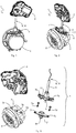
- the Figures 1 and 2 show various perspective views of the locking system 1, whereas the Figure 3 shows an individual representation of the locking system 1 in a perspective view.
- the locking system 1 comprises a locking drive 2, a charging socket or a charging plug receptacle 3, into which the charging plug (not shown in detail) can be inserted for charging the motor vehicle, an adapter element 4 and a locking element 5.
- the adapter element 4 is on the outer edge 6 of the as Charging socket formed charging plug receptacle 3 mounted, for which purpose a screw connection 7 as used in the embodiment shown is used.
- the screw connection 7 is formed by screws 7a, corresponding through bores 7b and 7c, which are formed in the adapter element 4, and bores 7d in the outer edge 6 of the charging plug receptacle 3 (see for example Figure 3 ), wherein for mounting the adapter element 4 on the charging plug receptacle 3, the screws 7a are inserted through the through-holes 7b, 7c and into the Bores 7d are screwed in.
- the adapter element 4 is arranged between the charging plug receptacle 3 and the locking drive 2.
- the locking element 5 is housed within the adapter element 4 (see for example Figures 4 and 5 ).
- the locking element 5 is between an unlocking position (see Figure 4 ) and a locking position (see Figure 5 ) movable.
- the locking element 5 In the unlocked position, the locking element 5 is arranged outside a receiving space 8 of the charging plug receptacle 3 which is used to receive the charging plug, whereas in the locking position the locking element 5 protrudes into the receiving space 8 of the charging plug receptacle 3 in order to be able to connect to a charging plug inserted in the receiving space 8 to be engageable.
- the charging plug receptacle 3 has a radially running through hole 3a through which the locking element 5 can be moved into the receiving space 8, the adapter element 4 having a passage through which the locking element 5 emerges from the adapter element 4 can dip through the through hole 3 a into the receiving space 8 in order to secure a charging plug in the receiving space 8.
- the first transmission element 9 transmits a movement force generated by the locking drive 2 to the locking element 5 in order to move the locking element 5 between the unlocking position and the locking position.
- the first transmission element 9 is a Bowden cable 10, which extends within a protective hose and which couples the locking drive 2 with the locking element 5 in terms of movement and connects it in an operative manner.
- the first transmission element 9 in the form of the Bowden cable 10 enables a spaced arrangement of the locking drive 2 and charging plug receptacle 3, so that although the locking system 1 according to the invention does not primarily Installation space can be saved, but due to the possibility of the spaced arrangement a separate or a predetermined spacing arrangement of the locking drive 2 and charging plug receptacle 3 is possible, so that at least for the locking drive 2 an arrangement can be selected at a position that is not is critical in terms of installation space.
- the first transmission element 9 or the Bowden cable 10 is surrounded by a sheath 11 which serves to protect the Bowden cable 10.
- a memory wire can also be used as the first transmission element 9. The memory wire is then also coupled in terms of movement to the locking element 5 in that the memory wire is energized, whereby it changes its length. After the power supply has ceased, the memory wire then resumes its original length.
- FIGs 4 and 5 show more details of the adapter element 4 of the locking system 1 according to the invention, wherein Figure 4 shows the locking element 5 in its unlocked position, in which the locking element 5 is arranged in the adapter element 5 in a retracted manner.
- the locking element 5 protrudes into the receiving space 8 of the charging plug receptacle 3 and can be in engagement with a charging plug in order to secure it in the receiving space 8.
- an elastic spring element 12 is arranged within the adapter element 4.
- the spring element 12 is designed as a compression spring, the ends of the spring element 12 being supported on the one hand on a stop surface 14 of the adapter element 4 and on the other hand on a support surface 15 of the locking element 5.
- the spring element 12 designed as a compression spring, exerts a force on the locking element 5, by means of which the locking element 5 is urged into its locking position. Consequently, the elastic spring element 12 extends between the stop surface 14 of the adapter element 4 and the support surface 15 of the locking element 5 and is supported on the surfaces 14 and 15, respectively. The locking element 5 is thus biased into its locking position.
- the locking drive 2 To the locking element 5 in the unlocked position To move, the locking drive 2 must pull on the first transmission element 9 in order to move the blocking element 5 out of the receiving space 8 of the charging plug receptacle 3.
- the locking drive 2 not only has to generate a movement force which counteracts the force of the elastic spring element 12, but is also greater than the force of the elastic spring element 12 in order to move the locking element 5 from the locking position into the unlocking position by means of the first transmission element 9.
- the locking drive 2 comprises a two-part housing with an upper shell 16 and a lower shell 17, the upper shell 16 and the lower shell 17 being connected to one another in a sealing manner by means of a clip connection to protect against dust and moisture.
- a self-locking worm gear 18 is arranged within the two-part housing of the locking drive 2. With the aid of the self-locking worm gear 18, the locking element 5 can be securely held in the unlocked position against the force of the elastic spring element 12.
- the self-locking worm gear 18 comprises a helical worm 18a which, when rotated, rotates a gear 18b which engages in this and to which a longitudinal end of the first transmission element 9 is attached.
- the self-locking effect is achieved because the worm gear 18 can only be driven via a drive shaft and not via the worm 18a.
- the drive shaft is driven by an electric motor 19, which is also arranged within the housing of the locking drive 2. So that the Bowden cable 10, as the first transmission element 9, can also properly roll up and down on the gear 18b of the locking drive 2 without fear of malfunction, a Bowden cable guide 20 is provided on the locking drive 2, which is located in the area of the passage opening of the housing of the Locking drive 2 is arranged and the Bowden cable 10 leads to the gear 18b.
- the adapter element 4 in the illustrated embodiment is designed as a component with a two-part housing and comprises a base element 21 and a cover element 22, which are connected to one another to form the housing of the adapter element 4.
- the base element 21 of the adapter element 4 has a movement space 23 (see Figure 4 ), in which the locking element 5 is positioned and which allows a movement of the locking element 5 in the radial direction to the charging plug receptacle 3.
- the locking element 5 can move between its unlocking position (see Figure 4 ) and its locking position (see Figure 5 ) move.
- the cover element 22 has a compression-expansion space 24 (see FIG Figure 5 ) on.
- the elastic spring element 12 is arranged within the compression-expansion space 24 and can expand in order to urge the locking element 5 into the locking position with the aid of the spring force.
- a section of the movement space 23 serves at the same time as a compression-expansion space 24 when the locking element 5 moves into the locking position.
- a bayonet connection 25 can also be seen, by means of which the base element 21 can be fastened to the cover element 22.
- the bayonet connection 25 is formed by two locking arms 27 arranged diametrically to one another when viewed from the center 26 of the base element 21 and corresponding holding recesses 28 in the cover element 22 in which the locking arms 27 engage.
- the two-part housing of the adapter element 4 is in the order of Figures 11, 12 and 13 assembled by placing the base element 21 on the cover element 22, whereby the locking element 5 is arranged within a through opening 29 of the base element 21.
- the base element 21 is then then moved relative to the cover element 22 in the direction of the arrow 30 in FIG Figure 12 rotated, whereby the locking arms 27 engage in the holding recesses 28 and fix the base element 21 on the cover element 22, as shown in FIG Figure 13 shown is.
- the adapter element 4 assembled in this way can now be attached to the charging connector receptacle 3.
- the cover element 22 fastened to the base element 21 and the base element 21 are jointly fastened to the charging plug receptacle 3 via the screw connection 7.
- the cover element 22 shown corresponds to a basic design which can be expanded by a guide element 31, as shown in FIGS Figures 10 to 13 can be seen.
- the guide element 31 can optionally be the in Figure 9 can be added. However, it can also be integrally formed on the outside of the cover element 22 of the adapter element 4 and thus made in one piece with the cover element 22.
- the Bowden cable 10 can be guided at an angle, as a result of which the flexibility of the arrangement of the locking drive 2 is further increased. This is because, with the aid of the guide element 31, the direction of the force generated by the locking drive 2 does not have to match the direction in which the locking element 5 has to be moved in order to be transferred into the unlocking position.
- the tubular guide element 31 thus guides a section of the first transmission element 9.
- Figure 14 finally shows a second transmission element 32 which is connected to the blocking element 5.
- the second transmission element 32 can be operated manually by a person in order to move the locking element 5 into the unlocking position.
- the locking element 5 can thus also be actuated mechanically, which could be the case, for example, in the case of an emergency actuation if the electric motor 19 should have failed.
Landscapes
- Engineering & Computer Science (AREA)
- Power Engineering (AREA)
- Transportation (AREA)
- Mechanical Engineering (AREA)
- Computer Security & Cryptography (AREA)
- Details Of Connecting Devices For Male And Female Coupling (AREA)
- Electric Propulsion And Braking For Vehicles (AREA)
- Lock And Its Accessories (AREA)
Description
- Die Erfindung richtet sich auf ein Verriegelungssystem für einen Ladestecker eines elektrisch betriebenen Kraftfahrzeugs, aufweisend einen Verriegelungsantrieb, eine Ladestecker-Aufnahme, in welche der Ladestecker zum Laden des Kraftfahrzeugs einsteckbar ist, ein an dem Außenrand der Ladestecker-Aufnahme montiertes Adapterelement, welches zwischen der Ladestecker-Aufnahme und dem Verriegelungsantrieb angeordnet ist, und ein Sperrelement, welches in dem Adapterelement untergebracht ist und mittels des Verriegelungsantriebs zwischen einer Entriegelungsposition, in welcher das Sperrelement außerhalb eines zur Aufnahme des Ladesteckers dienenden Aufnahmeraumes der Ladestecker-Aufnahme angeordnet ist, und einer Verriegelungsposition, in welcher das Sperrelement in den Aufnahmeraum der Ladestecker-Aufnahme hineinragt und mit dem Ladestecker in Eingriff bringbar ist, bewegbar ist, wobei zwischen dem Adapterelement und dem Verriegelungsantrieb ein erstes Übertragungselement angeordnet ist, welches eine von dem Verriegelungsantrieb erzeugte Bewegungskraft auf das Sperrelement zur Bewegung des Sperrelements zwischen der Entriegelungsposition und der Verriegelungsposition überträgt und welches eine beabstandete Anordnung von Verriegelungsantrieb und Ladestecker-Aufnahme ermöglicht.
- Ein Verriegelungssystem der Eingangs bezeichneten Art ist zum Beispiel aus der
DE 20 2013 009554 U1 , derWO 2011/120719 , derDE 10 2009 043845 A1 , derWO 2014/063140 A1 und derUS 2013/089999A1 bekannt. - Ferner ist ein Verriegelungssystem aus der
DE 10 2011 056 130 A1 bekannt und dient zur Verriegelung eines Ladesteckers, welcher in eine Ladesteckdose bzw. Ladestecker-Aufnahme einsteckbar ist, die am Kraftfahrzeug und/oder an einer Ladesäule angeordnet ist. Dieses bekannte Verriegelungssystem umfasst einen Verriegelungsantrieb und die Ladestecker-Aufnahme, wobei der Verriegelungsantrieb über ein Adapterelement mit der Ladestecker-Aufnahme fest verbunden ist. Genauer gesagt ist der Verriegelungsantrieb mit Hilfe des Adapterelements an der Ladestecker-Aufnahme befestigt. Ein Sperrelement ist in dem Verriegelungsantrieb integriert. Dabei bewegt der Verriegelungsantrieb das Sperrelement zwischen einer Verriegelungsposition, bei welcher das Sperrelement durch das Adapterelement in die Ladestecker-Aufnahme hinein bewegt ist und mit einem Ladestecker in Eingriff bringbar ist, und einer Entriegelungsposition, in welcher das Sperrelement aus der Ladestecker-Aufnahme zurückgezogen angeordnet ist, bewegbar ist. Von Nachteil bei diesem bekannten Verriegelungssystem ist es, dass das System aufgrund des Verriegelungsantriebs, der über das Adapterelement direkt an der Ladestecker-Aufnahme montiert ist, sehr viel Bauraum in Anspruch nimmt, was insbesondere dann von Nachteil ist, wenn die Ladestecker-Aufnahme an einem Kraftfahrzeug ausgebildet ist und ein Ladestecker beim Aufladen mit Hilfe des Sperrelements in der Ladestecker-Aufnahme fixiert werden soll. - Der Erfindung liegt die Aufgabe zugrunde eine Lösung zu schaffen, die auf konstruktiv einfache Weise und kostengünstig ein Verriegelungssystem bereitstellt, welches eine Bauraumersparnis bewirkt und darüber hinaus auch bei engen Bauraumverhältnissen eingesetzt werden kann.
- Bei einem Verriegelungssystem der Eingangs bezeichneten Art wird die Aufgabe erfindungsgemäß dadurch gelöst, dass das Adapterelement als wenigstens zweiteiliges Bauteil ausgebildet ist, welches ein einen Bewegungsraum für das Sperrelement aufweisendes Basiselement und ein über eine Bajonett-Verbindung an dem Basiselement befestigbares Deckelelement umfasst, wobei das Deckelelement einen Kompressions-Expansions-Raum aufweist und das an dem Basiselement befestigte Deckelelement und das Basiselement gemeinsam über eine Schraubverbindung an der Ladestecker-Aufnahme befestigt sind, wobei in dem Adapterelement innerhalb des Kompressions-Expansions-Raums ein elastisches Federelement vorgesehen ist, welches eine das Sperrelement in die Verriegelungsposition drängende Kraft auf das Sperrelement ausübt. Im Sinne der Erfindung ist unter einer beabstandeten Anordnung zu verstehen, dass der Verriegelungsantrieb und die Ladestecker-Aufnahme in einem vorgegebenen Abstand zueinander angeordnet sind, wodurch es möglich ist, dass der Verriegelungsantrieb einem anderen Bauraum als die Ladestecker-Aufnahme zugeordnet ist. Dabei ist der Ladestecker nicht Bestandteil des erfindungsgemäßen Systems.
- Vorteilhafte und zweckmäßige Ausgestaltungen und Weiterbildungen der Erfindung ergeben sich aus den Unteransprüchen.
- Durch die Erfindung wird ein Verriegelungssystem zur Verfügung gestellt, das sich durch eine funktionsgerechte Konstruktion auszeichnet und einen einfachen und kostengünstigen Aufbau aufweist. Dadurch, dass zwischen dem Adapterelement und dem Verriegelungsantrieb ein erstes Übertragungselement angeordnet ist, ist es möglich, dass der Verriegelungsantrieb entfernt von der Ladestecker-Aufnahme angeordnet werden kann. Dadurch kann die Ladestecker-Aufnahme auch an einer Position angeordnet werden, die lediglich einen Bauraum für die Ladestecker-Aufnahme und nicht für den Verriegelungsantrieb aufweist. Der Verriegelungsantrieb kann hingegen an einer Position angebracht sein, die einen ausreichenden Einbauraum aufweist, der aber entfernt von bzw. in einem vorgegebenen Abstand zu der Ladestecker-Aufnahme angeordnet ist. Über das erste Übertragungselement ist aber das Sperrelement in dem Adapterelement, welches wiederum auf der Ladestecker-Aufnahme montiert ist, bewegungsgekoppelt. Im Gegensatz zum Stand der Technik ist das Sperrelement nicht mehr innerhalb des Verriegelungsantriebs sondern innerhalb des Adapterelements untergebracht. Auf diese Weise ist erfindungsgemäß ein sehr flexibles Verriegelungssystem bereitgestellt. Durch die beabstandete Anordnung des Verriegelungsantriebs von der Ladestecker-Aufnahme mit dem daran montierten Adapterelement kann der an der Ladestecker-Aufnahme geschaffene Bauraum dazu genutzt werden, einen im Gegensatz zu den bekannten Systemen größeren Verriegelungsweg für das Sperrelement vorzusehen, damit eine noch sicherere Verriegelung mit dem Ladestecker möglich ist. Denn durch den gewonnenen Bauraum kann ein variabler und größerer Hub des Sperrelements, also der Bewegungsweg des Sperrelements zwischen der Entriegelungsposition und der Verriegelungsposition, realisiert werden. Ferner erlaubt es die Zweiteiligkeit, das Basiselement und das Deckelelement unabhängig voneinander unterschiedlich auszubilden und somit an verschiedene Aspekte anzupassen, wie beispielsweise einer unterschiedlichen Ausgestaltung des Kompressions-Expansions-Raumes unter Berücksichtigung des elastischen Federelements, was für eine konstruktive Flexibilität sorgt.
- Bei dem erfindungsgemäßen Verriegelungssystems ist es von Vorteil, wenn in dem Adapterelement ein elastisches Federelement vorgesehen ist, welches eine das Sperrelement in die Verriegelungsposition drängende Kraft auf das Sperrelement ausübt. Auf diese Weise muss der Verriegelungsantrieb das Sperrelement in nur eine Richtung, nämlich in Richtung der Entriegelungsposition, bewegen. Der Verriegelungsantrieb muss folglich nur dann in Betrieb sein, wenn das Sperrelement in die Entriegelungsposition bewegt werden muss, so dass auf diese Weise für das System auch noch Energie eingespart werden kann.
- Konstruktiv besonders günstig ist es in Ausgestaltung des erfindungsgemäßen Verriegelungssystems, wenn sich das elastische Federelement zwischen einer Anschlagfläche des Adapterelements und einer Abstützfläche des Sperrelements erstreckt und sich jeweils daran abstützt.
- Die Erfindung sieht in weiterer Ausgestaltung vor, dass die von dem Verriegelungsantrieb erzeugte Bewegungskraft eine entgegen der Kraft des elastischen Federelements wirkende Kraft ist, um das Sperrelement mittels des ersten Übertragungselements aus der Verriegelungsposition in die Entriegelungsposition zu bewegen. Mit anderen Worten muss der Verriegelungsantrieb nur dann eine Kraft aufbringen, wenn das Sperrelement in die Entriegelungsposition bewegt werden muss.
- Eine kostengünstige Lösung zur konstruktiven Realisierung des ersten Übertragungselements besteht in Ausgestaltung der Erfindung darin, dass das erste Übertragungselement ein Bowdenzug ist, welcher den Verriegelungsantrieb über das Adapterelement mit dem Sperrelement bewegungskoppelt.
- Mit Hilfe einer mechanischen Serviceentriegelung, die auch als Notentriegelung verwendet werden kann, kann das Sperrelement auch ohne Inbetriebnahme des Verriegelungsantriebs aus seiner Verriegelungsposition in die Entriegelungsposition bewegt werden. Zu diesem Zweck sieht die Erfindung in weiterer Ausgestaltung vor, dass ein zweites Übertragungselement mit dem Sperrelement verbunden ist, wobei das zweite Übertragungselement manuell von einer Person betätigbar ist, um das Sperrelement in die Entriegelungsposition zu bewegen.
- Damit das Sperrelement auch sicher in der Entriegelungsposition, insbesondere gegen die Kraft des elastischen Federelements, gehalten werden kann, sieht die Erfindung in weiterer Ausgestaltung vor, dass der Verriegelungsantrieb ein selbsthemmendes Schneckengetriebe umfasst. Bei dem Schneckengetriebe handelt es sich um eine schraubenförmige Schnecke, die bei Drehbewegung ein in dieses eingreifende Zahnrad dreht. Die selbsthemmende Wirkung wird dadurch erzielt, weil sich das Schneckengetriebe nur über die Antriebswelle und nicht über die Abtriebswelle antreiben lässt.
- In einer weiteren Ausgestaltung ist vorgesehen, dass bei dem erfindungsgemäßen Verriegelungssystem die Bajonett-Verbindung von zwei vom Zentrum des Basiselements aus betrachtet diametral zueinander angeordneten Verriegelungsarmen und dazu korrespondierenden Halteausnehmungen in dem Deckelelement, in welche die Verriegelungsarme eingreifen, gebildet ist. Mit Hilfe der Bajonett-Verbindung ist das zweiteilig ausgebildete Adapterelement schnell und ohne Hilfe eines Werkzeugs demontierbar, so dass ohne viel Aufwand entweder das Basiselement oder das Deckelelement getauscht werden können, wobei natürlich nach der Demontage auch Bauteile innerhalb des Adapterelements getauscht und ersetzt werden können, wie zum Beispiel das Sperrelement oder das Federelement.
- Schließlich sieht die Erfindung zur Erhöhung der Anwendungsflexibilität vor, dass auf der Außenseite des Adapterelements ein schlauchförmiges Führungselement angeformt ist, durch welches sich ein Abschnitt des ersten Übertragungselements erstreckt und welches das erste Übertragungselement abschnittsweise führt. Mit Hilfe des Führungselements kann die Kraftrichtung des ersten Übertragungselements gelenkt und umgeleitet werden, so dass die Anordnung des Verriegelungsantriebs und der Ladestecker-Aufnahme frei wählbar ist.
- Es versteht sich, dass die vorstehend genannten und nachstehend noch zu erläuternden Merkmale nicht nur in der jeweils angegebenen Kombination, sondern auch in anderen Kombinationen oder in Alleinstellung verwendbar sind, ohne den Rahmen der vorliegenden Erfindung zu verlassen. Der Rahmen der Erfindung ist nur durch die Ansprüche definiert.
- Weitere Einzelheiten, Merkmale und Vorteile des Gegenstandes der Erfindung ergeben sich aus der nachfolgenden Beschreibung im Zusammenhang mit der Zeichnung, in der beispielhaft ein bevorzugtes Ausführungsbeispiel der Erfindung dargestellt ist. In der Zeichnung zeigt:
-
Figur 1 ein erfindungsgemäßes Verriegelungssystem in perspektivischer Ansicht, -
Figur 2 eine weitere perspektivische Darstellung des Verriegelungssystems, -
Figur 3 eine Einzelteildarstellung des erfindungsgemäßen Verriegelungssystems, -
Figur 4 in seitlicher Schnittansicht ein Sperrelement des Verriegelungssystems in seiner Entriegelungsposition, -
Figur 5 in seitlicher Schnittansicht das Sperrelement des Verriegelungssystems in seiner Verriegelungsposition, -
Figur 6 eine Darstellung von oben auf einen geöffneten Verriegelungsantrieb des erfindungsgemäßen Verriegelungssystems, -
Figur 7 eine Darstellung von unten auf den geöffneten Verriegelungsantrieb des erfindungsgemäßen Verriegelungssystems, -
Figur 8 eine schematische und perspektivische Darstellung einer Bowdenzugführung, die an dem Verriegelungsantrieb vorgesehen ist, -
Figur 9 ein Deckelelement eines Adapterelements des erfindungsgemäßen Verriegelungssystems in perspektivischer Darstellung, -
Figur 10 ein anderes Deckelelement des Adapterelements des erfindungsgemäßen Verriegelungssystems in perspektivischer Darstellung, -
Figur 11 das Deckelelement ausFigur 10 und ein Basiselement, die zusammen das Adapterelement ausbilden, in perspektivischer Einzelteildarstellung, -
Figur 12 das Deckelelement und das Basiselement vor deren Montage in perspektivischer Ansicht, -
Figur 13 das Deckelelement und das Basiselement im montierten Zustand in perspektivischer Ansicht und -
Figur 14 ein Sperrelement des Verriegelungssystems mit mechanischer Serviceverriegelung in perspektivischer Ansicht, wobei ein erstes und ein zweites Übertragungselement an dem Sperrelement zu dessen Bewegung angebracht sind. - In den
Figuren 1 bis 3 ist ein erfindungsgemäßes Verriegelungssystem 1 dargestellt, welches zur Verriegelung eines nicht näher dargestellten Ladesteckers dient, wobei der Ladestecker zum Aufladen eines Energiespeichers eines elektrisch betriebenen Kraftfahrzeugs verwendet wird. DieFiguren 1 und 2 zeigen verschiedene, perspektivische Darstellungen des Verriegelungssystems 1, wohingegen dieFigur 3 eine Einzelteildarstellung des Verriegelungssystems 1 in perspektivischer Ansicht zeigt. Das Verriegelungssystem 1 umfasst einen Verriegelungsantrieb 2, eine Ladesteckdose bzw. eine Ladestecker-Aufnahme 3, in welche der nicht näher dargestellte Ladestecker zum Laden des Kraftfahrzeugs einsteckbar ist, ein Adapterelement 4 und ein Sperrelement 5. Das Adapterelement 4 ist an dem Außenrand 6 der als Ladesteckdose ausgebildeten Ladestecker-Aufnahme 3 montiert, wozu zum Beispiel eine wie in dem gezeigten Ausführungsbeispiel verwendete Schraubverbindung 7 dient. Die Schraubverbindung 7 wird von Schrauben 7a, entsprechenden Durchgangsbohrungen 7b und 7c, die im Adapterelement 4 ausgeformt sind, und Bohrungen 7d in dem Außenrand 6 der Ladestecker-Aufnahme 3 gebildet (siehe zum BeispielFigur 3 ), wobei zur Montage des Adapterelements 4 an der Ladestecker-Aufnahme 3 die Schrauben 7a durch die Durchgangsbohrungen 7b, 7c hindurch gesteckt und in die Bohrungen 7d eingeschraubt sind. Das Adapterelement 4 ist zwischen der Ladestecker-Aufnahme 3 und dem Verriegelungsantrieb 2 angeordnet. Das Sperrelement 5 ist innerhalb des Adapterelements 4 untergebracht (siehe zum BeispielFiguren 4 und 5 ). Mit Hilfe des Verriegelungsantriebs 2 ist das Sperrelement 5 zwischen einer Entriegelungsposition (sieheFigur 4 ) und einer Verriegelungsposition (sieheFigur 5 ) bewegbar. Dabei ist das Sperrelement 5 in Entriegelungsposition außerhalb eines zur Aufnahme des Ladesteckers dienenden Aufnahmeraumes 8 der Ladestecker-Aufnahme 3 angeordnet, wohingegen in der Verriegelungsposition das Sperrelement 5 in den Aufnahmeraum 8 der Ladestecker-Aufnahme 3 hineinragt, um mit einem in dem Aufnahmeraum 8 eingesteckten Ladestecker in Eingriff bringbar zu sein. Um in den Aufnahmeraum 8 hineinzuragen, weist die Ladestecker-Aufnahme 3 ein radial verlaufendes Durchgangsloch 3a auf, durch das hindurch das Sperrelement 5 in den Aufnahmeraum 8 bewegbar ist, wobei das Adapterelement 4 einen Durchgang aufweist, durch den das Sperrelement 5 aus dem Adapterelement 4 durch das Durchgangsloch 3a in den Aufnahmeraum 8 eintauchen kann, um einen Ladestecker in dem Aufnahmeraum 8 zu sichern. Die Ladestecker-Aufnahme 3, die an einem elektrisch betriebenen Kraftfahrzeug oder an einer Ladesäule angeordnet ist und auch als Ladesteckdose bezeichnet werden darf, ist erfindungsgemäß von dem Verriegelungsantrieb 2 beabstandet angeordnet, wobei ein erstes Übertragungselement 9 das Sperrelement 5 mit dem Verriegelungsantrieb 2 wirkverbindet. Das erste Übertragungselement 9 überträgt eine von dem Verriegelungsantrieb 2 erzeugte Bewegungskraft auf das Sperrelement 5, um das Sperrelement 5 zwischen der Entriegelungsposition und der Verriegelungsposition zu bewegen. Das erste Übertragungselement 9 ist ein Bowdenzug 10, welcher sich innerhalb eines Schutzschlauches erstreckt und den Verriegelungsantrieb 2 mit dem Sperrelement 5 bewegungskoppelt und wirkverbindet. Das erste Übertragungselement 9 in Form des Bowdenzugs 10 ermöglicht eine beabstandete Anordnung von Verriegelungsantrieb 2 und Ladestecker-Aufnahme 3, so dass zwar mit dem erfindungsgemäßen Verriegelungssystem 1 nicht primär Bauraum eingespart werden kann, jedoch infolge der Möglichkeit der beabstandeten Anordnung eine getrennte bzw. einen vorgegebenen Abstand aufweisende Anordnung von Verriegelungsantrieb 2 und Ladestecker-Aufnahme 3 möglich ist, so dass wenigstens für den Verriegelungsantrieb 2 eine Anordnung an einer Position gewählt werden kann, die nicht kritisch in Bezug auf den Bauraum ist. Das erste Übertragungselement 9 bzw. der Bowdenzug 10 ist in dem dargestellten Ausführungsbeispiel von einer Umhüllung 11 umgeben, die dem Schutz des Bowdenzugs 10 dient. Als Alternative zu einem Bowdenzug 10 kann auch ein Memorydraht als erstes Übertragungselement 9 verwendet werden. Der Memorydraht ist dann ebenfalls mit dem Sperrelement 5 bewegungsgekoppelt, indem der Memorydraht bestromt wird, wodurch er seine Länge ändert. Nach Entfall der Bestromung nimmt der Memorydraht dann wieder seine Ausgangslänge ein. - Die
Figuren 4 und 5 zeigen nähere Details des Adapterelements 4 des erfindungsgemäßen Verriegelungssystems 1, wobeiFigur 4 das Sperrelement 5 in seiner Entriegelungsposition zeigt, in welcher das Sperrelement 5 zurückgezogen in dem Adapterelement 5 angeordnet ist. InFigur 5 ragt das Sperrelement 5 hingegen in den Aufnahmeraum 8 der Ladestecker-Aufnahme 3 hinein und kann mit einem Ladestecker in Eingriff stehen, um diesen in dem Aufnahmeraum 8 zu sichern. Wie denFiguren 3 und4 ferner zu entnehmen ist, ist innerhalb des Adapterelements 4 ein elastisches Federelement 12 angeordnet. Das Federelement 12 ist als Druckfeder ausgebildet, wobei sich die Enden des Federelements 12 einerseits an einer Anschlagfläche 14 des Adapterelements 4 und andererseits an einer Abstützfläche 15 des Sperrelements 5 abstützen. Das als Druckfeder ausgebildete Federelement 12 übt auf das Sperrelement 5 eine Kraft aus, durch die das Sperrelement 5 in seine Verriegelungsposition gedrängt wird. Folglich erstreckt sich das elastische Federelement 12 zwischen der Anschlagfläche 14 des Adapterelements 4 und der Abstützfläche 15 des Sperrelements 5 und stützt sich jeweils an den Flächen 14 und 15 ab. Das Sperrelement 5 ist somit in seine Verriegelungsposition vorgespannt. Um das Sperrelement 5 in die Entriegelungsposition zu bewegen, muss der Verriegelungsantrieb 2 an dem ersten Übertragungselement 9 ziehen, um das Sperrelement 5 aus dem Aufnahmeraum 8 der Ladestecker-Aufnahme 3 herauszubewegen. Dabei muss der Verriegelungsantrieb 2 nicht nur eine Bewegungskraft, die der Kraft des elastischen Federelements 12 entgegenwirkt, sondern auch größer ist als die Kraft des elastischen Federelements 12 erzeugen, um das Sperrelement 5 mittels des ersten Übertragungselements 9 aus der Verriegelungsposition in die Entriegelungsposition zu bewegen. - In den
Figuren 6, 7 und 8 sind weitere Details des erfindungsgemäßen Verriegelungssystems 1 und insbesondere des Verriegelungsantriebs 2 dargestellt. Der Verriegelungsantrieb 2 umfasst ein zweiteiliges Gehäuse mit einer Oberschale 16 und einer Unterschale 17, wobei die Oberschale 16 und die Unterschale 17 mittels einer Clip-Verbindung dichtend zum Schutz gegen Staub und Feuchtigkeit miteinander verbunden sind. Innerhalb des zweiteiligen Gehäuses des Verriegelungsantriebs 2 ist ein selbsthemmendes Schneckengetriebe 18 angeordnet. Mit Hilfe des selbsthemmenden Schneckengetriebes 18 kann das Sperrelement 5 sicher in der Entriegelungsposition gegen die Kraft des elastischen Federelements 12 gehalten werden. Das selbsthemmende Schneckengetriebe 18 umfasst eine schraubenförmige Schnecke 18a, die bei Drehbewegung ein in dieses eingreifende Zahnrad 18b dreht, an welchem ein Längsende des ersten Übertragungselements 9 befestigt ist. Die selbsthemmende Wirkung wird dadurch erzielt, weil sich das Schneckengetriebe 18 nur über eine Antriebswelle und nicht über die Schnecke 18a antreiben lässt. Die Antriebswelle wird von einem Elektromotor 19 angetrieben, der ebenfalls innerhalb des Gehäuses des Verriegelungsantriebs 2 angeordnet ist. Damit sich der Bowdenzug 10 als das erste Übertragungselement 9 auch richtig an dem Zahnrad 18b des Verriegelungsantriebs 2 auf- und abrollen kann, ohne dass eine Funktionsstörung zu befürchten ist, ist am Verriegelungsantrieb 2 eine Bowdenzugführung 20 vorgesehen, die im Bereich der Durchtrittsöffnung des Gehäuses des Verriegelungsantriebs 2 angeordnet ist und den Bowdenzug 10 zu dem Zahnrad 18b führt. - Wie bereits in der Einzelteildarstellung der
Figur 3 angedeutet und mit Bezug auf dieFiguren 9 bis 13 ersichtlich, ist das Adapterelement 4 bei der dargestellten Ausführungsform als ein Bauteil mit einem zweiteiligen Gehäuse ausgeführt und umfasst ein Basiselement 21 und ein Deckelelement 22, die zur Bildung des Gehäuses des Adapterelements 4 miteinander verbunden werden. Das Basiselement 21 des Adapterelements 4 weist einen Bewegungsraum 23 (sieheFigur 4 ) auf, in welchem das Sperrelement 5 positioniert ist und der eine Bewegung des Sperrelements 5 in radialer Richtung zur Ladestecker-Aufnahme 3 zulässt. In dem Bewegungsraum 23 kann sich das Sperrelement 5 zwischen seiner Entriegelungsposition (sieheFigur 4 ) und seiner Verriegelungsposition (sieheFigur 5 ) bewegen. Das Deckelelement 22 hingegen weist einen Kompressions-Expansions-Raum 24 (sieheFigur 5 ) auf. Innerhalb des Kompressions-Expansions-Raums 24 ist das elastische Federelement 12 angeordnet und kann sich ausdehnen, um das Sperrelement 5 mit Hilfe der Federkraft in die Verriegelungsposition zu drängen. Wie insbesondere ausFigur 5 ersichtlich ist, dient ein Abschnitt des Bewegungsraumes 23 gleichzeitig als Kompressions-Expansions-Raum 24, wenn sich das Sperrelement 5 in die Verriegelungsposition bewegt. Aus denFiguren 9 bis 13 ist ferner eine Bajonett-Verbindung 25 ersichtlich, durch die das Basiselement 21 an dem Deckelelement 22 befestigbar ist. Die Bajonett-Verbindung 25 ist von zwei vom Zentrum 26 des Basiselements 21 aus betrachtet diametral zueinander angeordneten Verriegelungsarmen 27 und dazu korrespondierenden Halteausnehmungen 28 in dem Deckelelement 22, in welche die Verriegelungsarme 27 eingreifen, gebildet. Das zweiteilige Gehäuse des Adapterelements 4 wird in der Reihenfolge derFiguren 11, 12 und 13 zusammengebaut, indem das Basiselement 21 auf das Deckelelement 22 aufgesetzt wird, wodurch das Sperrelement 5 innerhalb einer Durchgangsöffnung 29 des Basiselements 21 angeordnet wird. Anschließend wird das Basiselement 21 dann relativ zu dem Deckelelement 22 in Richtung des Pfeils 30 inFigur 12 gedreht, wodurch die Verriegelungsarme 27 in die Halteausnehmungen 28 eingreifen und das Basiselement 21 an dem Deckelelement 22 fixieren, wie es inFigur 13 gezeigt ist. Das so zusammengebaute Adapterelement 4 kann nun an der Ladestecker-Aufnahme 3 befestigt werden. Wie vorstehend bereits beschrieben, sind das an dem Basiselement 21 befestigte Deckelelement 22 und das Basiselement 21 gemeinsam über die Schraubverbindung 7 an der Ladestecker-Aufnahme 3 befestigt. - Das in
Figur 9 gezeigte Deckelelement 22 entspricht einer Basisausführung, welche um ein Führungselement 31 erweiterbar ist, wie aus denFiguren 10 bis 13 ersichtlich ist. Das Führungselement 31 kann optional der inFigur 9 gezeigten Basisausführung hinzugefügt werden. Es kann aber auch an der Außenseite des Deckelelements 22 des Adapterelements 4 angeformt und dadurch einstückig mit dem Deckelelement 22 ausgeführt sein. Durch das schlauchförmige Führungselement 31 kann der Bowdenzug 10 abgewinkelt geführt werden, wodurch die Flexibilität der Anordnung des Verriegelungsantriebs 2 weiter erhöht wird. Denn mit Hilfe des Führungselements 31 muss die Richtung der Kraft, die von dem Verriegelungsantrieb 2 erzeugt wird, nicht mit der Richtung übereinstimmen, in die das Sperrelement 5 bewegt werden muss, um in die Entriegelungsposition überführt zu werden. Das schlauchförmige Führungselement 31 führt somit einen Abschnitt des ersten Übertragungselements 9. -
Figur 14 zeigt schließlich ein zweites Übertragungselement 32, welches mit dem Sperrelement 5 verbunden ist. Das zweite Übertragungselement 32 ist manuell von einer Person betätigbar, um das Sperrelement 5 in die Entriegelungsposition zu bewegen. Somit kann das Sperrelement 5 auch mechanisch betätigt werden, was beispielsweise bei einer Notbetätigung der Fall sein könnte, wenn der Elektromotor 19 ausgefallen sein sollte. - Die vorstehend beschriebene Erfindung ist selbstverständlich nicht auf die beschriebene und dargestellte Ausführungsform beschränkt.
Claims (8)
- Verriegelungssystem (1) für einen Ladestecker eines elektrisch betriebenen Kraftfahrzeugs, aufweisend
einen Verriegelungsantrieb (2),
eine Ladestecker-Aufnahme (3), in welche der Ladestecker zum Laden des Kraftfahrzeugs einsteckbar ist,
ein an dem Außenrand (6) der Ladestecker-Aufnahme (3) montiertes Adapterelement (4), welches zwischen der Ladestecker-Aufnahme (3) und dem Verriegelungsantrieb (2) angeordnet ist, und
ein Sperrelement (5), welches in dem Adapterelement (4) untergebracht ist und mittels des Verriegelungsantriebs (2) zwischen einer Entriegelungsposition, in welcher das Sperrelement (5) außerhalb eines zur Aufnahme des Ladesteckers dienenden Aufnahmeraumes (8) der Ladestecker-Aufnahme (3) angeordnet ist, und einer Verriegelungsposition, in welcher das Sperrelement (5) in den Aufnahmeraum (8) der Ladestecker-Aufnahme (3) hineinragt und mit dem Ladestecker in Eingriff bringbar ist, bewegbar ist,
wobei zwischen dem Adapterelement (4) und dem Verriegelungsantrieb (2) ein erstes Übertragungselement (9) angeordnet ist, welches eine von dem Verriegelungsantrieb (2) erzeugte Bewegungskraft auf das Sperrelement (5) zur Bewegung des Sperrelements (5) zwischen der Entriegelungsposition und der Verriegelungsposition überträgt und welches eine beabstandete Anordnung von Verriegelungsantrieb (2) und Ladestecker-Aufnahme (3) ermöglicht, 11 wobei das Adapterelement (4) als wenigstens zweiteiliges Bauteil ausgebildet ist,
dadurch gekennzeichnet, dass das Adapterelement (4) ein einen Bewegungsraum (23) für das Sperrelement (5) aufweisendes Basiselement (21) und ein über eine Bajonett-Verbindung (25) an dem Basiselement (21) befestigbares Deckelelement (22) umfasst, wobei das Deckelelement (22) einen Kompressions-Expansions-Raum (24) aufweist und das an dem Basiselement (21) befestigte Deckelelement (22) und das Basiselement (21) gemeinsam über eine Schraubverbindung (7) an der Ladestecker-Aufnahme (3) befestigt sind, wobei in dem Adapterelement (4) innerhalb des Kompressions-Expansions-Raums (24) ein elastisches Federelement (12) vorgesehen ist, welches eine das Sperrelement (5) in die Verriegelungsposition drängende Kraft auf das Sperrelement (5) ausübt. - Verriegelungssystem (1) nach Anspruch 1, dadurch gekennzeichnet, dass sich das elastische Federelement (12) zwischen einer Anschlagfläche (14) des Adapterelements (4) und einer Abstützfläche (15) des Sperrelements (5) erstreckt und sich jeweils daran abstützt.
- Verriegelungssystem (1) nach Anspruch 1 oder 2, dadurch gekennzeichnet, dass die von dem Verriegelungsantrieb (2) erzeugte Bewegungskraft eine entgegen der Kraft des elastischen Federelements (12) wirkende Kraft ist, um das Sperrelement (5) mittels des ersten Übertragungselements (9) aus der Verriegelungsposition in die Entriegelungsposition zu bewegen.
- Verriegelungssystem (1) nach einem der vorhergehenden Ansprüche, dadurch gekennzeichnet, dass das erste Übertragungselement (9) ein Bowdenzug (10) ist, welcher den Verriegelungsantrieb (2) über das Adapterelement (4) mit dem Sperrelement (5) bewegungskoppelt.
- Verriegelungssystem (1) nach einem der vorhergehenden Ansprüche, dadurch gekennzeichnet, dass ein zweites Übertragungselement (32) mit dem Sperrelement (5) verbunden ist, wobei das zweite Übertragungselement (32) manuell von einer Person betätigbar ist, um das Sperrelement (5) in die Entriegelungsposition zu bewegen.
- Verriegelungssystem (1) nach einem der vorhergehenden Ansprüche, dadurch gekennzeichnet, dass der Verriegelungsantrieb (2) ein selbsthemmendes Schneckengetriebe (16) umfasst.
- Verriegelungssystem (1) nach Anspruch 1, dadurch gekennzeichnet, dass die Bajonett-Verbindung (25) von zwei vom Zentrum (26) des Basiselements (21) aus betrachtet diametral zueinander angeordneten Verriegelungsarmen (27) und dazu korrespondierenden Halteausnehmungen (28) in dem Deckelelement (22), in welche die Verriegelungsarme (27) eingreifen, gebildet ist.
- Verriegelungssystem (1) nach einem der vorhergehenden Ansprüche, dadurch gekennzeichnet, dass auf der Außenseite des Adapterelements (4) ein schlauchförmiges Führungselement (31) angeformt ist, durch welches sich ein Abschnitt des ersten Übertragungselements (9) erstreckt und welches das erste Übertragungselement (9) abschnittsweise führt.
Applications Claiming Priority (2)
| Application Number | Priority Date | Filing Date | Title |
|---|---|---|---|
| DE102015108831.2A DE102015108831A1 (de) | 2015-06-03 | 2015-06-03 | Verriegelungssystem für einen Ladestecker |
| PCT/EP2016/061246 WO2016193011A1 (de) | 2015-06-03 | 2016-05-19 | Verriegelungssystem für einen ladestecker |
Publications (2)
| Publication Number | Publication Date |
|---|---|
| EP3304655A1 EP3304655A1 (de) | 2018-04-11 |
| EP3304655B1 true EP3304655B1 (de) | 2020-09-23 |
Family
ID=56101426
Family Applications (1)
| Application Number | Title | Priority Date | Filing Date |
|---|---|---|---|
| EP16727142.8A Not-in-force EP3304655B1 (de) | 2015-06-03 | 2016-05-19 | Verriegelungssystem für einen ladestecker |
Country Status (3)
| Country | Link |
|---|---|
| EP (1) | EP3304655B1 (de) |
| DE (1) | DE102015108831A1 (de) |
| WO (1) | WO2016193011A1 (de) |
Families Citing this family (8)
| Publication number | Priority date | Publication date | Assignee | Title |
|---|---|---|---|---|
| CN109713520B (zh) * | 2019-01-22 | 2023-12-01 | 上海蔚来汽车有限公司 | 插拔机构、插头装置、电池架及充换电站 |
| EP3763558A1 (de) * | 2019-07-09 | 2021-01-13 | Jabil Inc. | Elektromechanischer aktuator zum verriegeln eines ladekabels in einer ladeaufnahme |
| DE102019132110A1 (de) * | 2019-11-27 | 2021-05-27 | Kiekert Aktiengesellschaft | Elektrische ladevorrichtung eines kraftfahrzeuges |
| DE102020102209B4 (de) * | 2020-01-30 | 2024-02-08 | Phoenix Contact E-Mobility Gmbh | Verriegelungseinrichtung zur Montage eines Aktuators an einer Ladesteckdose |
| DE102020132026A1 (de) * | 2020-12-02 | 2022-06-02 | Kiekert Aktiengesellschaft | Elektromotorische Verriegelungseinheit für eine elektrische Ladevorrichtung eines Kraftfahrzeuges |
| DE102020132024A1 (de) | 2020-12-02 | 2022-06-02 | Kiekert Aktiengesellschaft | Ladevorrichtung für ein Kraftfahrzeug |
| DE102021128976A1 (de) | 2021-11-08 | 2023-05-11 | Kiekert Aktiengesellschaft | Kraftfahrzeug-technische Stellvorrichtung |
| CN116923134B (zh) * | 2023-09-18 | 2023-11-17 | 贵阳中安科技集团有限公司 | 一种用于新能源汽车充电线的定位装置 |
Family Cites Families (8)
| Publication number | Priority date | Publication date | Assignee | Title |
|---|---|---|---|---|
| DE102009043845A1 (de) * | 2009-08-25 | 2011-03-03 | Amad - Mennekes Holding Gmbh & Co. Kg | Steckvorrichtungssystem mit Aktuator |
| US9944172B2 (en) * | 2010-03-31 | 2018-04-17 | Kiekert Ag | Actuator for a motor vehicle and locking device and method |
| DE102011050783A1 (de) * | 2011-01-27 | 2012-08-02 | Huf Hülsbeck & Fürst Gmbh & Co. Kg | Verriegelungsvorrichtung, insbesondere für einen Stecker |
| US8550833B2 (en) * | 2011-10-07 | 2013-10-08 | Ford Global Technologies, Llc | Locking apparatus for electric vehicle charging connector |
| DE102011056130A1 (de) * | 2011-12-07 | 2013-06-13 | Huf Hülsbeck & Fürst Gmbh & Co. Kg | Verriegelungsvorrichtung für einen Ladestecker eines elektrisch betriebenen Kraftfahrzeugs |
| DE102012013998A1 (de) * | 2012-07-02 | 2014-01-02 | Huf Hülsbeck & Fürst Gmbh & Co. Kg | Verriegelungsvorrichtung für einen elektrostecker |
| WO2014063140A1 (en) * | 2012-10-19 | 2014-04-24 | Lear Corporation | Electrical connector assembly |
| DE202013009554U1 (de) * | 2013-10-28 | 2015-01-29 | Kiekert Aktiengesellschaft | Elektrische Steckverbindung |
-
2015
- 2015-06-03 DE DE102015108831.2A patent/DE102015108831A1/de not_active Withdrawn
-
2016
- 2016-05-19 WO PCT/EP2016/061246 patent/WO2016193011A1/de not_active Ceased
- 2016-05-19 EP EP16727142.8A patent/EP3304655B1/de not_active Not-in-force
Non-Patent Citations (1)
| Title |
|---|
| None * |
Also Published As
| Publication number | Publication date |
|---|---|
| WO2016193011A1 (de) | 2016-12-08 |
| DE102015108831A1 (de) | 2016-12-08 |
| EP3304655A1 (de) | 2018-04-11 |
Similar Documents
| Publication | Publication Date | Title |
|---|---|---|
| EP3304655B1 (de) | Verriegelungssystem für einen ladestecker | |
| EP1475253B1 (de) | Anhängekupplung für Kraftfahrzeuge | |
| EP3131795B1 (de) | Wischeranlage | |
| DE102012110648B4 (de) | Verriegelungselement, Verbindungsanordnung, Anordnung aus einem ersten Bauteil und einem zweiten Bauteil und Verfahren zur Montage einer solchen Anordnung | |
| EP3259802B1 (de) | Antennenmodul | |
| EP3710711A1 (de) | Befestiger und verwendung eines befestigers | |
| DE102011005598A1 (de) | Befestigungsvorrichtung zur Anordnung an einer Montageschiene | |
| DE102018108830A1 (de) | System aus einem Anbauteil und einem Halteelement | |
| EP2019765B1 (de) | Vorrichtung und verfahren zur befestigung eines wischermotors an ein wischergestänge | |
| DE102018100458B4 (de) | Getriebegehäuseeinheit und Getriebeeinheit mit keilförmigem Ausgleichselement zum Axialspielausgleich | |
| DE102013101083A1 (de) | Hilfswerkzeug zur Montage eines Stoßdämpfers | |
| DE102015216715A1 (de) | Verstellbare Lenksäule für Kraftfahrzeuge mit Energieabsorber für den Fahrzeugcrash | |
| EP3326249B1 (de) | Anordnung aus einem dachaufbau und einem befestigunssystem für die befestigung des dachaufbaus in einem ausschnitt auf dem dach eines schaltschranks | |
| EP2459894B1 (de) | Lagereinrichtung | |
| EP4219304B1 (de) | Kopplungsvorrichtung für eine verbindungsstange | |
| EP3523160B1 (de) | Getriebeanordnung für einen spindelantrieb, spindelantrieb und fahrzeugsitz | |
| EP2886402B1 (de) | Antriebsträger für eine Antriebseinheit und elektrische Lenkverriegelung mit einem solchen Antriebsträger | |
| DE29505752U1 (de) | Vorrichtung zum Verbinden von Platten mittels Verschraubung | |
| DE102012017685B4 (de) | Kompensationsvorrichtung für einen Bowdenzug | |
| EP3425217B1 (de) | Rastbolzen für ein stativ | |
| WO2018103876A1 (de) | Triebkopf und antriebstrangvorrichtung für ein kraftfahrzeug | |
| DE102018100999A1 (de) | Vorrichtung zum positionsgerechten Befestigen einer Antennenanordnung | |
| DE102016119519A1 (de) | Lenksäulenmodul für ein Fahrzeug, Lenksäulenanordnung, Fahrzeug und Verfahren zum Zusammenbau einer Lenksäulenanordnung | |
| EP2429868B1 (de) | Befestigungsanordnung | |
| DE102012105530B4 (de) | Verriegelungsvorrichtung |
Legal Events
| Date | Code | Title | Description |
|---|---|---|---|
| STAA | Information on the status of an ep patent application or granted ep patent |
Free format text: STATUS: THE INTERNATIONAL PUBLICATION HAS BEEN MADE |
|
| PUAI | Public reference made under article 153(3) epc to a published international application that has entered the european phase |
Free format text: ORIGINAL CODE: 0009012 |
|
| STAA | Information on the status of an ep patent application or granted ep patent |
Free format text: STATUS: REQUEST FOR EXAMINATION WAS MADE |
|
| 17P | Request for examination filed |
Effective date: 20180103 |
|
| AK | Designated contracting states |
Kind code of ref document: A1 Designated state(s): AL AT BE BG CH CY CZ DE DK EE ES FI FR GB GR HR HU IE IS IT LI LT LU LV MC MK MT NL NO PL PT RO RS SE SI SK SM TR |
|
| AX | Request for extension of the european patent |
Extension state: BA ME |
|
| DAV | Request for validation of the european patent (deleted) | ||
| DAX | Request for extension of the european patent (deleted) | ||
| STAA | Information on the status of an ep patent application or granted ep patent |
Free format text: STATUS: EXAMINATION IS IN PROGRESS |
|
| 17Q | First examination report despatched |
Effective date: 20191206 |
|
| GRAP | Despatch of communication of intention to grant a patent |
Free format text: ORIGINAL CODE: EPIDOSNIGR1 |
|
| STAA | Information on the status of an ep patent application or granted ep patent |
Free format text: STATUS: GRANT OF PATENT IS INTENDED |
|
| RIC1 | Information provided on ipc code assigned before grant |
Ipc: B60L 53/16 20190101ALI20200520BHEP Ipc: H01R 13/627 20060101ALN20200520BHEP Ipc: H01R 13/639 20060101AFI20200520BHEP |
|
| RIC1 | Information provided on ipc code assigned before grant |
Ipc: H01R 13/639 20060101AFI20200527BHEP Ipc: B60L 53/16 20190101ALI20200527BHEP Ipc: H01R 13/627 20060101ALN20200527BHEP |
|
| INTG | Intention to grant announced |
Effective date: 20200616 |
|
| GRAS | Grant fee paid |
Free format text: ORIGINAL CODE: EPIDOSNIGR3 |
|
| GRAA | (expected) grant |
Free format text: ORIGINAL CODE: 0009210 |
|
| STAA | Information on the status of an ep patent application or granted ep patent |
Free format text: STATUS: THE PATENT HAS BEEN GRANTED |
|
| AK | Designated contracting states |
Kind code of ref document: B1 Designated state(s): AL AT BE BG CH CY CZ DE DK EE ES FI FR GB GR HR HU IE IS IT LI LT LU LV MC MK MT NL NO PL PT RO RS SE SI SK SM TR |
|
| REG | Reference to a national code |
Ref country code: GB Ref legal event code: FG4D Free format text: NOT ENGLISH |
|
| REG | Reference to a national code |
Ref country code: CH Ref legal event code: EP |
|
| REG | Reference to a national code |
Ref country code: DE Ref legal event code: R096 Ref document number: 502016011256 Country of ref document: DE |
|
| REG | Reference to a national code |
Ref country code: IE Ref legal event code: FG4D Free format text: LANGUAGE OF EP DOCUMENT: GERMAN |
|
| REG | Reference to a national code |
Ref country code: AT Ref legal event code: REF Ref document number: 1317333 Country of ref document: AT Kind code of ref document: T Effective date: 20201015 |
|
| PG25 | Lapsed in a contracting state [announced via postgrant information from national office to epo] |
Ref country code: FI Free format text: LAPSE BECAUSE OF FAILURE TO SUBMIT A TRANSLATION OF THE DESCRIPTION OR TO PAY THE FEE WITHIN THE PRESCRIBED TIME-LIMIT Effective date: 20200923 Ref country code: BG Free format text: LAPSE BECAUSE OF FAILURE TO SUBMIT A TRANSLATION OF THE DESCRIPTION OR TO PAY THE FEE WITHIN THE PRESCRIBED TIME-LIMIT Effective date: 20201223 Ref country code: NO Free format text: LAPSE BECAUSE OF FAILURE TO SUBMIT A TRANSLATION OF THE DESCRIPTION OR TO PAY THE FEE WITHIN THE PRESCRIBED TIME-LIMIT Effective date: 20201223 Ref country code: GR Free format text: LAPSE BECAUSE OF FAILURE TO SUBMIT A TRANSLATION OF THE DESCRIPTION OR TO PAY THE FEE WITHIN THE PRESCRIBED TIME-LIMIT Effective date: 20201224 Ref country code: HR Free format text: LAPSE BECAUSE OF FAILURE TO SUBMIT A TRANSLATION OF THE DESCRIPTION OR TO PAY THE FEE WITHIN THE PRESCRIBED TIME-LIMIT Effective date: 20200923 Ref country code: SE Free format text: LAPSE BECAUSE OF FAILURE TO SUBMIT A TRANSLATION OF THE DESCRIPTION OR TO PAY THE FEE WITHIN THE PRESCRIBED TIME-LIMIT Effective date: 20200923 |
|
| PG25 | Lapsed in a contracting state [announced via postgrant information from national office to epo] |
Ref country code: RS Free format text: LAPSE BECAUSE OF FAILURE TO SUBMIT A TRANSLATION OF THE DESCRIPTION OR TO PAY THE FEE WITHIN THE PRESCRIBED TIME-LIMIT Effective date: 20200923 Ref country code: LV Free format text: LAPSE BECAUSE OF FAILURE TO SUBMIT A TRANSLATION OF THE DESCRIPTION OR TO PAY THE FEE WITHIN THE PRESCRIBED TIME-LIMIT Effective date: 20200923 |
|
| REG | Reference to a national code |
Ref country code: NL Ref legal event code: MP Effective date: 20200923 |
|
| REG | Reference to a national code |
Ref country code: LT Ref legal event code: MG4D |
|
| PG25 | Lapsed in a contracting state [announced via postgrant information from national office to epo] |
Ref country code: EE Free format text: LAPSE BECAUSE OF FAILURE TO SUBMIT A TRANSLATION OF THE DESCRIPTION OR TO PAY THE FEE WITHIN THE PRESCRIBED TIME-LIMIT Effective date: 20200923 Ref country code: LT Free format text: LAPSE BECAUSE OF FAILURE TO SUBMIT A TRANSLATION OF THE DESCRIPTION OR TO PAY THE FEE WITHIN THE PRESCRIBED TIME-LIMIT Effective date: 20200923 Ref country code: SM Free format text: LAPSE BECAUSE OF FAILURE TO SUBMIT A TRANSLATION OF THE DESCRIPTION OR TO PAY THE FEE WITHIN THE PRESCRIBED TIME-LIMIT Effective date: 20200923 Ref country code: RO Free format text: LAPSE BECAUSE OF FAILURE TO SUBMIT A TRANSLATION OF THE DESCRIPTION OR TO PAY THE FEE WITHIN THE PRESCRIBED TIME-LIMIT Effective date: 20200923 Ref country code: PT Free format text: LAPSE BECAUSE OF FAILURE TO SUBMIT A TRANSLATION OF THE DESCRIPTION OR TO PAY THE FEE WITHIN THE PRESCRIBED TIME-LIMIT Effective date: 20210125 Ref country code: CZ Free format text: LAPSE BECAUSE OF FAILURE TO SUBMIT A TRANSLATION OF THE DESCRIPTION OR TO PAY THE FEE WITHIN THE PRESCRIBED TIME-LIMIT Effective date: 20200923 |
|
| PG25 | Lapsed in a contracting state [announced via postgrant information from national office to epo] |
Ref country code: ES Free format text: LAPSE BECAUSE OF FAILURE TO SUBMIT A TRANSLATION OF THE DESCRIPTION OR TO PAY THE FEE WITHIN THE PRESCRIBED TIME-LIMIT Effective date: 20200923 Ref country code: AL Free format text: LAPSE BECAUSE OF FAILURE TO SUBMIT A TRANSLATION OF THE DESCRIPTION OR TO PAY THE FEE WITHIN THE PRESCRIBED TIME-LIMIT Effective date: 20200923 Ref country code: IS Free format text: LAPSE BECAUSE OF FAILURE TO SUBMIT A TRANSLATION OF THE DESCRIPTION OR TO PAY THE FEE WITHIN THE PRESCRIBED TIME-LIMIT Effective date: 20210123 Ref country code: PL Free format text: LAPSE BECAUSE OF FAILURE TO SUBMIT A TRANSLATION OF THE DESCRIPTION OR TO PAY THE FEE WITHIN THE PRESCRIBED TIME-LIMIT Effective date: 20200923 |
|
| REG | Reference to a national code |
Ref country code: DE Ref legal event code: R097 Ref document number: 502016011256 Country of ref document: DE |
|
| PG25 | Lapsed in a contracting state [announced via postgrant information from national office to epo] |
Ref country code: SK Free format text: LAPSE BECAUSE OF FAILURE TO SUBMIT A TRANSLATION OF THE DESCRIPTION OR TO PAY THE FEE WITHIN THE PRESCRIBED TIME-LIMIT Effective date: 20200923 |
|
| PLBE | No opposition filed within time limit |
Free format text: ORIGINAL CODE: 0009261 |
|
| STAA | Information on the status of an ep patent application or granted ep patent |
Free format text: STATUS: NO OPPOSITION FILED WITHIN TIME LIMIT |
|
| PG25 | Lapsed in a contracting state [announced via postgrant information from national office to epo] |
Ref country code: SI Free format text: LAPSE BECAUSE OF FAILURE TO SUBMIT A TRANSLATION OF THE DESCRIPTION OR TO PAY THE FEE WITHIN THE PRESCRIBED TIME-LIMIT Effective date: 20200923 Ref country code: DK Free format text: LAPSE BECAUSE OF FAILURE TO SUBMIT A TRANSLATION OF THE DESCRIPTION OR TO PAY THE FEE WITHIN THE PRESCRIBED TIME-LIMIT Effective date: 20200923 |
|
| 26N | No opposition filed |
Effective date: 20210624 |
|
| PG25 | Lapsed in a contracting state [announced via postgrant information from national office to epo] |
Ref country code: IT Free format text: LAPSE BECAUSE OF FAILURE TO SUBMIT A TRANSLATION OF THE DESCRIPTION OR TO PAY THE FEE WITHIN THE PRESCRIBED TIME-LIMIT Effective date: 20200923 |
|
| REG | Reference to a national code |
Ref country code: DE Ref legal event code: R119 Ref document number: 502016011256 Country of ref document: DE |
|
| REG | Reference to a national code |
Ref country code: CH Ref legal event code: PL |
|
| GBPC | Gb: european patent ceased through non-payment of renewal fee |
Effective date: 20210519 |
|
| PG25 | Lapsed in a contracting state [announced via postgrant information from national office to epo] |
Ref country code: CH Free format text: LAPSE BECAUSE OF NON-PAYMENT OF DUE FEES Effective date: 20210531 Ref country code: LU Free format text: LAPSE BECAUSE OF NON-PAYMENT OF DUE FEES Effective date: 20210519 Ref country code: MC Free format text: LAPSE BECAUSE OF FAILURE TO SUBMIT A TRANSLATION OF THE DESCRIPTION OR TO PAY THE FEE WITHIN THE PRESCRIBED TIME-LIMIT Effective date: 20200923 Ref country code: LI Free format text: LAPSE BECAUSE OF NON-PAYMENT OF DUE FEES Effective date: 20210531 |
|
| REG | Reference to a national code |
Ref country code: BE Ref legal event code: MM Effective date: 20210531 |
|
| PG25 | Lapsed in a contracting state [announced via postgrant information from national office to epo] |
Ref country code: IE Free format text: LAPSE BECAUSE OF NON-PAYMENT OF DUE FEES Effective date: 20210519 Ref country code: GB Free format text: LAPSE BECAUSE OF NON-PAYMENT OF DUE FEES Effective date: 20210519 Ref country code: DE Free format text: LAPSE BECAUSE OF NON-PAYMENT OF DUE FEES Effective date: 20211201 |
|
| PG25 | Lapsed in a contracting state [announced via postgrant information from national office to epo] |
Ref country code: FR Free format text: LAPSE BECAUSE OF NON-PAYMENT OF DUE FEES Effective date: 20210531 |
|
| REG | Reference to a national code |
Ref country code: AT Ref legal event code: MM01 Ref document number: 1317333 Country of ref document: AT Kind code of ref document: T Effective date: 20210519 |
|
| PG25 | Lapsed in a contracting state [announced via postgrant information from national office to epo] |
Ref country code: BE Free format text: LAPSE BECAUSE OF NON-PAYMENT OF DUE FEES Effective date: 20210531 |
|
| PG25 | Lapsed in a contracting state [announced via postgrant information from national office to epo] |
Ref country code: AT Free format text: LAPSE BECAUSE OF NON-PAYMENT OF DUE FEES Effective date: 20210519 |
|
| PG25 | Lapsed in a contracting state [announced via postgrant information from national office to epo] |
Ref country code: NL Free format text: LAPSE BECAUSE OF NON-PAYMENT OF DUE FEES Effective date: 20200923 Ref country code: CY Free format text: LAPSE BECAUSE OF FAILURE TO SUBMIT A TRANSLATION OF THE DESCRIPTION OR TO PAY THE FEE WITHIN THE PRESCRIBED TIME-LIMIT Effective date: 20200923 |
|
| PG25 | Lapsed in a contracting state [announced via postgrant information from national office to epo] |
Ref country code: HU Free format text: LAPSE BECAUSE OF FAILURE TO SUBMIT A TRANSLATION OF THE DESCRIPTION OR TO PAY THE FEE WITHIN THE PRESCRIBED TIME-LIMIT; INVALID AB INITIO Effective date: 20160519 |
|
| PG25 | Lapsed in a contracting state [announced via postgrant information from national office to epo] |
Ref country code: MK Free format text: LAPSE BECAUSE OF FAILURE TO SUBMIT A TRANSLATION OF THE DESCRIPTION OR TO PAY THE FEE WITHIN THE PRESCRIBED TIME-LIMIT Effective date: 20200923 |
|
| PG25 | Lapsed in a contracting state [announced via postgrant information from national office to epo] |
Ref country code: MT Free format text: LAPSE BECAUSE OF FAILURE TO SUBMIT A TRANSLATION OF THE DESCRIPTION OR TO PAY THE FEE WITHIN THE PRESCRIBED TIME-LIMIT Effective date: 20200923 |
|
| PG25 | Lapsed in a contracting state [announced via postgrant information from national office to epo] |
Ref country code: TR Free format text: LAPSE BECAUSE OF FAILURE TO SUBMIT A TRANSLATION OF THE DESCRIPTION OR TO PAY THE FEE WITHIN THE PRESCRIBED TIME-LIMIT Effective date: 20200923 |