EP3304655B1 - Système de verrouillage pour un connecteur de charge - Google Patents
Système de verrouillage pour un connecteur de charge Download PDFInfo
- Publication number
- EP3304655B1 EP3304655B1 EP16727142.8A EP16727142A EP3304655B1 EP 3304655 B1 EP3304655 B1 EP 3304655B1 EP 16727142 A EP16727142 A EP 16727142A EP 3304655 B1 EP3304655 B1 EP 3304655B1
- Authority
- EP
- European Patent Office
- Prior art keywords
- locking
- charging plug
- adapter
- drive
- plug receptacle
- Prior art date
- Legal status (The legal status is an assumption and is not a legal conclusion. Google has not performed a legal analysis and makes no representation as to the accuracy of the status listed.)
- Not-in-force
Links
Images


Classifications
-
- H—ELECTRICITY
- H01—ELECTRIC ELEMENTS
- H01R—ELECTRICALLY-CONDUCTIVE CONNECTIONS; STRUCTURAL ASSOCIATIONS OF A PLURALITY OF MUTUALLY-INSULATED ELECTRICAL CONNECTING ELEMENTS; COUPLING DEVICES; CURRENT COLLECTORS
- H01R13/00—Details of coupling devices of the kinds covered by groups H01R12/70 or H01R24/00 - H01R33/00
- H01R13/62—Means for facilitating engagement or disengagement of coupling parts or for holding them in engagement
- H01R13/639—Additional means for holding or locking coupling parts together, after engagement, e.g. separate keylock, retainer strap
- H01R13/6397—Additional means for holding or locking coupling parts together, after engagement, e.g. separate keylock, retainer strap with means for preventing unauthorised use
-
- B—PERFORMING OPERATIONS; TRANSPORTING
- B60—VEHICLES IN GENERAL
- B60L—PROPULSION OF ELECTRICALLY-PROPELLED VEHICLES; SUPPLYING ELECTRIC POWER FOR AUXILIARY EQUIPMENT OF ELECTRICALLY-PROPELLED VEHICLES; ELECTRODYNAMIC BRAKE SYSTEMS FOR VEHICLES IN GENERAL; MAGNETIC SUSPENSION OR LEVITATION FOR VEHICLES; MONITORING OPERATING VARIABLES OF ELECTRICALLY-PROPELLED VEHICLES; ELECTRIC SAFETY DEVICES FOR ELECTRICALLY-PROPELLED VEHICLES
- B60L53/00—Methods of charging batteries, specially adapted for electric vehicles; Charging stations or on-board charging equipment therefor; Exchange of energy storage elements in electric vehicles
- B60L53/10—Methods of charging batteries, specially adapted for electric vehicles; Charging stations or on-board charging equipment therefor; Exchange of energy storage elements in electric vehicles characterised by the energy transfer between the charging station and the vehicle
- B60L53/14—Conductive energy transfer
- B60L53/16—Connectors, e.g. plugs or sockets, specially adapted for charging electric vehicles
-
- H—ELECTRICITY
- H01—ELECTRIC ELEMENTS
- H01R—ELECTRICALLY-CONDUCTIVE CONNECTIONS; STRUCTURAL ASSOCIATIONS OF A PLURALITY OF MUTUALLY-INSULATED ELECTRICAL CONNECTING ELEMENTS; COUPLING DEVICES; CURRENT COLLECTORS
- H01R13/00—Details of coupling devices of the kinds covered by groups H01R12/70 or H01R24/00 - H01R33/00
- H01R13/62—Means for facilitating engagement or disengagement of coupling parts or for holding them in engagement
- H01R13/627—Snap or like fastening
- H01R13/6278—Snap or like fastening comprising a pin snapping into a recess
-
- Y—GENERAL TAGGING OF NEW TECHNOLOGICAL DEVELOPMENTS; GENERAL TAGGING OF CROSS-SECTIONAL TECHNOLOGIES SPANNING OVER SEVERAL SECTIONS OF THE IPC; TECHNICAL SUBJECTS COVERED BY FORMER USPC CROSS-REFERENCE ART COLLECTIONS [XRACs] AND DIGESTS
- Y02—TECHNOLOGIES OR APPLICATIONS FOR MITIGATION OR ADAPTATION AGAINST CLIMATE CHANGE
- Y02T—CLIMATE CHANGE MITIGATION TECHNOLOGIES RELATED TO TRANSPORTATION
- Y02T10/00—Road transport of goods or passengers
- Y02T10/60—Other road transportation technologies with climate change mitigation effect
- Y02T10/70—Energy storage systems for electromobility, e.g. batteries
-
- Y—GENERAL TAGGING OF NEW TECHNOLOGICAL DEVELOPMENTS; GENERAL TAGGING OF CROSS-SECTIONAL TECHNOLOGIES SPANNING OVER SEVERAL SECTIONS OF THE IPC; TECHNICAL SUBJECTS COVERED BY FORMER USPC CROSS-REFERENCE ART COLLECTIONS [XRACs] AND DIGESTS
- Y02—TECHNOLOGIES OR APPLICATIONS FOR MITIGATION OR ADAPTATION AGAINST CLIMATE CHANGE
- Y02T—CLIMATE CHANGE MITIGATION TECHNOLOGIES RELATED TO TRANSPORTATION
- Y02T10/00—Road transport of goods or passengers
- Y02T10/60—Other road transportation technologies with climate change mitigation effect
- Y02T10/7072—Electromobility specific charging systems or methods for batteries, ultracapacitors, supercapacitors or double-layer capacitors
-
- Y—GENERAL TAGGING OF NEW TECHNOLOGICAL DEVELOPMENTS; GENERAL TAGGING OF CROSS-SECTIONAL TECHNOLOGIES SPANNING OVER SEVERAL SECTIONS OF THE IPC; TECHNICAL SUBJECTS COVERED BY FORMER USPC CROSS-REFERENCE ART COLLECTIONS [XRACs] AND DIGESTS
- Y02—TECHNOLOGIES OR APPLICATIONS FOR MITIGATION OR ADAPTATION AGAINST CLIMATE CHANGE
- Y02T—CLIMATE CHANGE MITIGATION TECHNOLOGIES RELATED TO TRANSPORTATION
- Y02T90/00—Enabling technologies or technologies with a potential or indirect contribution to GHG emissions mitigation
- Y02T90/10—Technologies relating to charging of electric vehicles
- Y02T90/14—Plug-in electric vehicles
Definitions
- the invention is directed to a locking system for a charging plug of an electrically operated motor vehicle, having a locking drive, a charging plug receptacle into which the charging plug can be inserted for charging the motor vehicle, an adapter element which is mounted on the outer edge of the charging plug receptacle and which is located between the charging plug -Recording and the locking drive is arranged, and a locking element, which is housed in the adapter element and by means of the locking drive between an unlocking position, in which the locking element is arranged outside a receiving space of the charging plug receptacle serving for receiving the charging plug, and a locking position, in which the locking element protrudes into the receiving space of the charging plug receptacle and can be brought into engagement with the charging plug, is movable, wherein a first transmission element is arranged between the adapter element and the locking drive, wel ches transmits a movement force generated by the locking drive to the locking element for moving the locking element between the unlocking position and the locking position and which enables a spaced
- a locking system of the type indicated is for example of the DE 20 2013 009554 U1 , of the WO 2011/120719 , of the DE 10 2009 043845 A1 , of the WO 2014/063140 A1 and the US 2013 / 089999A1 known.
- a locking system from the DE 10 2011 056 130 A1 known and is used to lock a charging plug which can be inserted into a charging socket or charging plug receptacle which is arranged on the motor vehicle and / or on a charging column.
- This known locking system comprises a locking drive and the charging plug receptacle, the locking drive via an adapter element with the Charging plug receptacle is firmly connected. More precisely, the locking drive is attached to the charging plug receptacle with the aid of the adapter element. A locking element is integrated in the locking drive.
- the locking drive moves the locking element between a locking position in which the locking element is moved into the charging plug receptacle by the adapter element and can be brought into engagement with a charging plug, and an unlocking position in which the locking element is arranged withdrawn from the charging plug receptacle , is movable.
- the disadvantage of this known locking system is that the system takes up a great deal of space due to the locking drive, which is mounted directly on the charging plug receptacle via the adapter element, which is particularly disadvantageous when the charging plug receptacle is attached to a Motor vehicle is designed and a charging plug is to be fixed in the charging plug receptacle during charging with the aid of the locking element.
- the invention is based on the object of creating a solution which, in a structurally simple manner and inexpensively, provides a locking system that saves installation space and can also be used in tight installation spaces.
- the adapter element is designed as an at least two-part component which comprises a base element having a movement space for the locking element and a cover element which can be fastened to the base element via a bayonet connection, the cover element has a compression-expansion space and the cover element fastened to the base element and the base element are fastened jointly to the charging plug receptacle via a screw connection, an elastic spring element being provided in the adapter element within the compression-expansion space, which is a locking element exerts an urging force on the locking element in the locking position.
- a spaced arrangement is to be understood as meaning that the The locking drive and the charging plug receptacle are arranged at a predetermined distance from one another, which makes it possible for the locking drive to be assigned to a different installation space than the charging plug receptacle.
- the charging plug is not part of the system according to the invention.
- the invention provides a locking system which is characterized by a functional construction and has a simple and inexpensive structure. Because a first transmission element is arranged between the adapter element and the locking drive, it is possible that the locking drive can be arranged away from the charging plug receptacle. As a result, the charging plug receptacle can also be arranged in a position that only has space for the charging plug receptacle and not for the locking drive.
- the locking drive on the other hand, can be attached at a position which has sufficient installation space, but which is located away from or at a predetermined distance from the charging plug receptacle.
- the blocking element in the adapter element which in turn is mounted on the charging plug receptacle, is coupled in terms of movement via the first transmission element.
- the locking element is no longer housed within the locking drive but within the adapter element.
- a very flexible locking system is provided according to the invention. Due to the spaced arrangement of the locking drive from the charging plug receptacle with the adapter element mounted on it, the space created on the charging plug receptacle can be used to provide a larger locking path for the locking element than in the known systems, so that an even more secure locking with the Charging plug is possible. Because of the space gained, a variable and larger stroke of the locking element, i.e. the movement path of the Locking element between the unlocking position and the locking position can be realized. Furthermore, the two-part design allows the base element and the cover element to be designed differently independently of one another and thus to be adapted to different aspects, such as a different design of the compression-expansion space taking into account the elastic spring element, which ensures structural flexibility.
- an elastic spring element is provided in the adapter element which exerts a force on the locking element that urges the locking element into the locking position.
- the locking drive has to move the locking element in only one direction, namely in the direction of the unlocking position.
- the locking drive therefore only has to be in operation when the locking element has to be moved into the unlocking position, so that energy can also be saved for the system in this way.
- the elastic spring element extends between a stop surface of the adapter element and a support surface of the locking element and is supported thereon.
- the invention provides in a further embodiment that the movement force generated by the locking drive is a force acting against the force of the elastic spring element in order to move the locking element out of the locking position into the unlocking position by means of the first transmission element.
- the locking drive only has to apply a force when the locking element has to be moved into the unlocked position.
- a cost-effective solution for constructively realizing the first transmission element is, in an embodiment of the invention, that the first transmission element is a Bowden cable, which couples the locking drive with the locking element via the adapter element.
- the locking element can also be moved from its locking position into the unlocking position without starting up the locking drive.
- the invention provides in a further embodiment that a second transmission element is connected to the locking element, wherein the second transmission element can be actuated manually by a person in order to move the locking element into the unlocking position.
- the invention provides in a further embodiment that the locking drive comprises a self-locking worm gear.
- the worm gear is a helical worm which rotates a gear wheel that engages in it when it rotates.
- the self-locking effect is achieved because the worm gear can only be driven via the drive shaft and not via the output shaft.
- the bayonet connection is formed by two locking arms, viewed from the center of the base element, diametrically opposite one another and corresponding holding recesses in the cover element, in which the locking arms engage.
- the invention provides that a tubular guide element is formed on the outside of the adapter element, through which a section of the first transmission element extends and which the first Transmission element leads in sections.
- the guide element With the help of the guide element, the direction of force of the first transmission element can be steered and diverted, so that the arrangement of the locking drive and the charging plug receptacle can be freely selected.
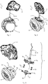
- a locking system 1 according to the invention is shown, which is used to lock a charging plug, not shown in detail, the charging plug being used to charge an energy store of an electrically operated motor vehicle.
- the Figures 1 and 2 show various perspective views of the locking system 1, whereas the Figure 3 shows an individual representation of the locking system 1 in a perspective view.
- the locking system 1 comprises a locking drive 2, a charging socket or a charging plug receptacle 3, into which the charging plug (not shown in detail) can be inserted for charging the motor vehicle, an adapter element 4 and a locking element 5.
- the adapter element 4 is on the outer edge 6 of the as Charging socket formed charging plug receptacle 3 mounted, for which purpose a screw connection 7 as used in the embodiment shown is used.
- the screw connection 7 is formed by screws 7a, corresponding through bores 7b and 7c, which are formed in the adapter element 4, and bores 7d in the outer edge 6 of the charging plug receptacle 3 (see for example Figure 3 ), wherein for mounting the adapter element 4 on the charging plug receptacle 3, the screws 7a are inserted through the through-holes 7b, 7c and into the Bores 7d are screwed in.
- the adapter element 4 is arranged between the charging plug receptacle 3 and the locking drive 2.
- the locking element 5 is housed within the adapter element 4 (see for example Figures 4 and 5 ).
- the locking element 5 is between an unlocking position (see Figure 4 ) and a locking position (see Figure 5 ) movable.
- the locking element 5 In the unlocked position, the locking element 5 is arranged outside a receiving space 8 of the charging plug receptacle 3 which is used to receive the charging plug, whereas in the locking position the locking element 5 protrudes into the receiving space 8 of the charging plug receptacle 3 in order to be able to connect to a charging plug inserted in the receiving space 8 to be engageable.
- the charging plug receptacle 3 has a radially running through hole 3a through which the locking element 5 can be moved into the receiving space 8, the adapter element 4 having a passage through which the locking element 5 emerges from the adapter element 4 can dip through the through hole 3 a into the receiving space 8 in order to secure a charging plug in the receiving space 8.
- the first transmission element 9 transmits a movement force generated by the locking drive 2 to the locking element 5 in order to move the locking element 5 between the unlocking position and the locking position.
- the first transmission element 9 is a Bowden cable 10, which extends within a protective hose and which couples the locking drive 2 with the locking element 5 in terms of movement and connects it in an operative manner.
- the first transmission element 9 in the form of the Bowden cable 10 enables a spaced arrangement of the locking drive 2 and charging plug receptacle 3, so that although the locking system 1 according to the invention does not primarily Installation space can be saved, but due to the possibility of the spaced arrangement a separate or a predetermined spacing arrangement of the locking drive 2 and charging plug receptacle 3 is possible, so that at least for the locking drive 2 an arrangement can be selected at a position that is not is critical in terms of installation space.
- the first transmission element 9 or the Bowden cable 10 is surrounded by a sheath 11 which serves to protect the Bowden cable 10.
- a memory wire can also be used as the first transmission element 9. The memory wire is then also coupled in terms of movement to the locking element 5 in that the memory wire is energized, whereby it changes its length. After the power supply has ceased, the memory wire then resumes its original length.
- FIGs 4 and 5 show more details of the adapter element 4 of the locking system 1 according to the invention, wherein Figure 4 shows the locking element 5 in its unlocked position, in which the locking element 5 is arranged in the adapter element 5 in a retracted manner.
- the locking element 5 protrudes into the receiving space 8 of the charging plug receptacle 3 and can be in engagement with a charging plug in order to secure it in the receiving space 8.
- an elastic spring element 12 is arranged within the adapter element 4.
- the spring element 12 is designed as a compression spring, the ends of the spring element 12 being supported on the one hand on a stop surface 14 of the adapter element 4 and on the other hand on a support surface 15 of the locking element 5.
- the spring element 12 designed as a compression spring, exerts a force on the locking element 5, by means of which the locking element 5 is urged into its locking position. Consequently, the elastic spring element 12 extends between the stop surface 14 of the adapter element 4 and the support surface 15 of the locking element 5 and is supported on the surfaces 14 and 15, respectively. The locking element 5 is thus biased into its locking position.
- the locking drive 2 To the locking element 5 in the unlocked position To move, the locking drive 2 must pull on the first transmission element 9 in order to move the blocking element 5 out of the receiving space 8 of the charging plug receptacle 3.
- the locking drive 2 not only has to generate a movement force which counteracts the force of the elastic spring element 12, but is also greater than the force of the elastic spring element 12 in order to move the locking element 5 from the locking position into the unlocking position by means of the first transmission element 9.
- the locking drive 2 comprises a two-part housing with an upper shell 16 and a lower shell 17, the upper shell 16 and the lower shell 17 being connected to one another in a sealing manner by means of a clip connection to protect against dust and moisture.
- a self-locking worm gear 18 is arranged within the two-part housing of the locking drive 2. With the aid of the self-locking worm gear 18, the locking element 5 can be securely held in the unlocked position against the force of the elastic spring element 12.
- the self-locking worm gear 18 comprises a helical worm 18a which, when rotated, rotates a gear 18b which engages in this and to which a longitudinal end of the first transmission element 9 is attached.
- the self-locking effect is achieved because the worm gear 18 can only be driven via a drive shaft and not via the worm 18a.
- the drive shaft is driven by an electric motor 19, which is also arranged within the housing of the locking drive 2. So that the Bowden cable 10, as the first transmission element 9, can also properly roll up and down on the gear 18b of the locking drive 2 without fear of malfunction, a Bowden cable guide 20 is provided on the locking drive 2, which is located in the area of the passage opening of the housing of the Locking drive 2 is arranged and the Bowden cable 10 leads to the gear 18b.
- the adapter element 4 in the illustrated embodiment is designed as a component with a two-part housing and comprises a base element 21 and a cover element 22, which are connected to one another to form the housing of the adapter element 4.
- the base element 21 of the adapter element 4 has a movement space 23 (see Figure 4 ), in which the locking element 5 is positioned and which allows a movement of the locking element 5 in the radial direction to the charging plug receptacle 3.
- the locking element 5 can move between its unlocking position (see Figure 4 ) and its locking position (see Figure 5 ) move.
- the cover element 22 has a compression-expansion space 24 (see FIG Figure 5 ) on.
- the elastic spring element 12 is arranged within the compression-expansion space 24 and can expand in order to urge the locking element 5 into the locking position with the aid of the spring force.
- a section of the movement space 23 serves at the same time as a compression-expansion space 24 when the locking element 5 moves into the locking position.
- a bayonet connection 25 can also be seen, by means of which the base element 21 can be fastened to the cover element 22.
- the bayonet connection 25 is formed by two locking arms 27 arranged diametrically to one another when viewed from the center 26 of the base element 21 and corresponding holding recesses 28 in the cover element 22 in which the locking arms 27 engage.
- the two-part housing of the adapter element 4 is in the order of Figures 11, 12 and 13 assembled by placing the base element 21 on the cover element 22, whereby the locking element 5 is arranged within a through opening 29 of the base element 21.
- the base element 21 is then then moved relative to the cover element 22 in the direction of the arrow 30 in FIG Figure 12 rotated, whereby the locking arms 27 engage in the holding recesses 28 and fix the base element 21 on the cover element 22, as shown in FIG Figure 13 shown is.
- the adapter element 4 assembled in this way can now be attached to the charging connector receptacle 3.
- the cover element 22 fastened to the base element 21 and the base element 21 are jointly fastened to the charging plug receptacle 3 via the screw connection 7.
- the cover element 22 shown corresponds to a basic design which can be expanded by a guide element 31, as shown in FIGS Figures 10 to 13 can be seen.
- the guide element 31 can optionally be the in Figure 9 can be added. However, it can also be integrally formed on the outside of the cover element 22 of the adapter element 4 and thus made in one piece with the cover element 22.
- the Bowden cable 10 can be guided at an angle, as a result of which the flexibility of the arrangement of the locking drive 2 is further increased. This is because, with the aid of the guide element 31, the direction of the force generated by the locking drive 2 does not have to match the direction in which the locking element 5 has to be moved in order to be transferred into the unlocking position.
- the tubular guide element 31 thus guides a section of the first transmission element 9.
- Figure 14 finally shows a second transmission element 32 which is connected to the blocking element 5.
- the second transmission element 32 can be operated manually by a person in order to move the locking element 5 into the unlocking position.
- the locking element 5 can thus also be actuated mechanically, which could be the case, for example, in the case of an emergency actuation if the electric motor 19 should have failed.
Landscapes
- Engineering & Computer Science (AREA)
- Power Engineering (AREA)
- Transportation (AREA)
- Mechanical Engineering (AREA)
- Computer Security & Cryptography (AREA)
- Details Of Connecting Devices For Male And Female Coupling (AREA)
- Electric Propulsion And Braking For Vehicles (AREA)
- Lock And Its Accessories (AREA)
Claims (8)
- Système de verrouillage (1) pour un connecteur de charge d'un véhicule automobile à entraînement électrique, comportant
un entraînement de verrouillage (2),
un logement de connecteur de charge (3) dans lequel le connecteur de charge peut être connecté pour charger le véhicule automobile,
un élément adaptateur (4) monté sur le bord extérieur (6) du logement de connecteur de charge (3), lequel est disposé entre le logement de connecteur de charge (3) et l'entraînement de verrouillage (2), et
un élément de blocage (5), lequel est incorporé dans l'élément adaptateur (4) et est mobile au moyen de l'entraînement de verrouillage (2) entre une position de déverrouillage, dans laquelle l'élément de blocage (5) est disposé en dehors d'un espace de logement (8) du logement de connecteur de charge (3) servant à loger le connecteur de charge et une position de verrouillage, dans laquelle l'élément de blocage (5) pénètre dans l'espace de logement (8) du logement de connecteur de charge (3) et peut être mis en prise avec le connecteur de charge,
sachant qu'entre l'élément adaptateur (4) et l'entraînement de verrouillage (2) est disposé un premier élément de transmission (9), lequel transmet une force de déplacement générée par l'entraînement de verrouillage (2) à l'élément de blocage (5) pour déplacer l'élément de blocage (5) entre la position de déverrouillage et la position de verrouillage et lequel permet un système espacé de l'entraînement de verrouillage (2) et du logement de connecteur de charge (3), sachant que l'élément adaptateur (4) est constitué comme un composant au moins en deux parties, caractérisé en ce que l'élément adaptateur (4) comprend un élément de base (21) comportant un espace de déplacement (23) pour l'élément de blocage (5) et un élément de couverture (22) fixable sur l'élément de base (21) par le biais d'un raccord à baïonnette (25), sachant que l'élément de couverture (22) comporte un espace compression-expansion (24) et l'élément de couverture (22) fixé à l'élément de base (21) et l'élément de base (21) sont fixés en commun par un raccord à vis (7) au logement de connecteur de charge (3), sachant que dans l'élément adaptateur (4), un élément à ressort (12) élastique est prévu à l'intérieur de l'espace compression-expansion (24), lequel exerce une force sur l'élément de blocage (5) repoussant l'élément de blocage (5) dans la position de verrouillage. - Système de verrouillage (1) selon la revendication 1, caractérisé en ce que l'élément à ressort (12) élastique s'étend entre une surface de butée (14) de l'élément adaptateur (4) et une surface d'appui (15) de l'élément de bocage (5) et s'appuie respectivement sur celles-ci.
- Système de verrouillage (1) selon la revendication 1 ou 2, caractérisé en ce que la force de déplacement générée par l'entraînement de verrouillage (2) est une force agissant à l'opposé de la force de l'élément à ressort (12) élastique pour déplacer l'élément de blocage (5) de la position de verrouillage à la position de déverrouillage au moyen du premier élément de transmission (9).
- Système de verrouillage (1) selon l'une quelconque des revendications précédentes, caractérisé en ce que le premier élément de transmission (9) est un câble Bowden (10), lequel couple en mouvement l'entraînement de verrouillage (2) par l'élément adaptateur (4) à l'élément de blocage (5).
- Système de verrouillage (1) selon l'une quelconque des revendications précédentes, caractérisé en ce qu'un deuxième élément de transmission (32) est relié à l'élément de blocage (5), sachant que le deuxième élément de transmission (32) est actionné manuellement par une personne pour déplacer l'élément de blocage (5) dans la position de déverrouillage.
- Système de verrouillage (1) selon l'une quelconque des revendications précédentes, caractérisé en ce que l'entraînement de verrouillage (2) comprend un engrenage à vis sans fin (16) autobloquant.
- Système de verrouillage (1) selon la revendication 1, caractérisé en ce que le raccord à baïonnette (25) est formé de deux bras de verrouillage (27) disposés diamétralement l'un par rapport à l'autre vus du centre (26) de l'élément de base (21) et d' évidements de retenue (28) correspondants à cet effet dans l'élément de couverture (22) dans lequel viennent en prise les bras de verrouillage (27).
- Système de verrouillage (1) selon l'une quelconque des revendications précédentes, caractérisé en ce que sur la face extérieure de l'élément adaptateur (4) est conformé un élément de guidage (31) de forme tubulaire à travers lequel s'étend une section du premier élément de transmission (9) et lequel guide par sections le premier élément de transmission (9).
Applications Claiming Priority (2)
| Application Number | Priority Date | Filing Date | Title |
|---|---|---|---|
| DE102015108831.2A DE102015108831A1 (de) | 2015-06-03 | 2015-06-03 | Verriegelungssystem für einen Ladestecker |
| PCT/EP2016/061246 WO2016193011A1 (fr) | 2015-06-03 | 2016-05-19 | Système de verrouillage pour un connecteur de charge |
Publications (2)
| Publication Number | Publication Date |
|---|---|
| EP3304655A1 EP3304655A1 (fr) | 2018-04-11 |
| EP3304655B1 true EP3304655B1 (fr) | 2020-09-23 |
Family
ID=56101426
Family Applications (1)
| Application Number | Title | Priority Date | Filing Date |
|---|---|---|---|
| EP16727142.8A Not-in-force EP3304655B1 (fr) | 2015-06-03 | 2016-05-19 | Système de verrouillage pour un connecteur de charge |
Country Status (3)
| Country | Link |
|---|---|
| EP (1) | EP3304655B1 (fr) |
| DE (1) | DE102015108831A1 (fr) |
| WO (1) | WO2016193011A1 (fr) |
Families Citing this family (8)
| Publication number | Priority date | Publication date | Assignee | Title |
|---|---|---|---|---|
| CN109713520B (zh) * | 2019-01-22 | 2023-12-01 | 上海蔚来汽车有限公司 | 插拔机构、插头装置、电池架及充换电站 |
| EP3763558A1 (fr) * | 2019-07-09 | 2021-01-13 | Jabil Inc. | Actionneur électromécanique pour verrouiller un câble de charge dans un réceptacle de charge |
| DE102019132110A1 (de) * | 2019-11-27 | 2021-05-27 | Kiekert Aktiengesellschaft | Elektrische ladevorrichtung eines kraftfahrzeuges |
| DE102020102209B4 (de) * | 2020-01-30 | 2024-02-08 | Phoenix Contact E-Mobility Gmbh | Verriegelungseinrichtung zur Montage eines Aktuators an einer Ladesteckdose |
| DE102020132026A1 (de) * | 2020-12-02 | 2022-06-02 | Kiekert Aktiengesellschaft | Elektromotorische Verriegelungseinheit für eine elektrische Ladevorrichtung eines Kraftfahrzeuges |
| DE102020132024A1 (de) | 2020-12-02 | 2022-06-02 | Kiekert Aktiengesellschaft | Ladevorrichtung für ein Kraftfahrzeug |
| DE102021128976A1 (de) | 2021-11-08 | 2023-05-11 | Kiekert Aktiengesellschaft | Kraftfahrzeug-technische Stellvorrichtung |
| CN116923134B (zh) * | 2023-09-18 | 2023-11-17 | 贵阳中安科技集团有限公司 | 一种用于新能源汽车充电线的定位装置 |
Family Cites Families (8)
| Publication number | Priority date | Publication date | Assignee | Title |
|---|---|---|---|---|
| DE102009043845A1 (de) * | 2009-08-25 | 2011-03-03 | Amad - Mennekes Holding Gmbh & Co. Kg | Steckvorrichtungssystem mit Aktuator |
| US9944172B2 (en) * | 2010-03-31 | 2018-04-17 | Kiekert Ag | Actuator for a motor vehicle and locking device and method |
| DE102011050783A1 (de) * | 2011-01-27 | 2012-08-02 | Huf Hülsbeck & Fürst Gmbh & Co. Kg | Verriegelungsvorrichtung, insbesondere für einen Stecker |
| US8550833B2 (en) * | 2011-10-07 | 2013-10-08 | Ford Global Technologies, Llc | Locking apparatus for electric vehicle charging connector |
| DE102011056130A1 (de) * | 2011-12-07 | 2013-06-13 | Huf Hülsbeck & Fürst Gmbh & Co. Kg | Verriegelungsvorrichtung für einen Ladestecker eines elektrisch betriebenen Kraftfahrzeugs |
| DE102012013998A1 (de) * | 2012-07-02 | 2014-01-02 | Huf Hülsbeck & Fürst Gmbh & Co. Kg | Verriegelungsvorrichtung für einen elektrostecker |
| WO2014063140A1 (fr) * | 2012-10-19 | 2014-04-24 | Lear Corporation | Ensemble connecteur électrique |
| DE202013009554U1 (de) * | 2013-10-28 | 2015-01-29 | Kiekert Aktiengesellschaft | Elektrische Steckverbindung |
-
2015
- 2015-06-03 DE DE102015108831.2A patent/DE102015108831A1/de not_active Withdrawn
-
2016
- 2016-05-19 WO PCT/EP2016/061246 patent/WO2016193011A1/fr not_active Ceased
- 2016-05-19 EP EP16727142.8A patent/EP3304655B1/fr not_active Not-in-force
Non-Patent Citations (1)
| Title |
|---|
| None * |
Also Published As
| Publication number | Publication date |
|---|---|
| WO2016193011A1 (fr) | 2016-12-08 |
| DE102015108831A1 (de) | 2016-12-08 |
| EP3304655A1 (fr) | 2018-04-11 |
Similar Documents
| Publication | Publication Date | Title |
|---|---|---|
| EP3304655B1 (fr) | Système de verrouillage pour un connecteur de charge | |
| EP1475253B1 (fr) | Attelage de remorque pour véhicules automobiles | |
| EP3131795B1 (fr) | Systeme d'essuie glace | |
| DE102012110648B4 (de) | Verriegelungselement, Verbindungsanordnung, Anordnung aus einem ersten Bauteil und einem zweiten Bauteil und Verfahren zur Montage einer solchen Anordnung | |
| EP3259802B1 (fr) | Module d'antenne | |
| EP3710711A1 (fr) | Dispositif de fixation et utilisation d'un dispositif de fixation | |
| DE102011005598A1 (de) | Befestigungsvorrichtung zur Anordnung an einer Montageschiene | |
| DE102018108830A1 (de) | System aus einem Anbauteil und einem Halteelement | |
| EP2019765B1 (fr) | Dispositif et procédé pour fixer un moteur d'essuie-glace sur une tringlerie d'essuie-glace | |
| DE102018100458B4 (de) | Getriebegehäuseeinheit und Getriebeeinheit mit keilförmigem Ausgleichselement zum Axialspielausgleich | |
| DE102013101083A1 (de) | Hilfswerkzeug zur Montage eines Stoßdämpfers | |
| DE102015216715A1 (de) | Verstellbare Lenksäule für Kraftfahrzeuge mit Energieabsorber für den Fahrzeugcrash | |
| EP3326249B1 (fr) | Agencement comprenant une partie haute de toit et un système de fixation pour la fixation de la partie haute de toit sur le toit d'une armoire électrique | |
| EP2459894B1 (fr) | Dispositif de palier à roulement | |
| EP4219304B1 (fr) | Dispositif d'accouplement pour une bielle de liaison | |
| EP3523160B1 (fr) | Agencement de transmission pour mécanisme d'entraînement de broche, entraînement de broche et siège de véhicule | |
| EP2886402B1 (fr) | Support d'entraînement pour une unité d'entraînement et verrouillage électrique de direction doté d'un tel support d'entraînement | |
| DE29505752U1 (de) | Vorrichtung zum Verbinden von Platten mittels Verschraubung | |
| DE102012017685B4 (de) | Kompensationsvorrichtung für einen Bowdenzug | |
| EP3425217B1 (fr) | Boulons d'arrêt pour un trépied | |
| WO2018103876A1 (fr) | Tête d'entraînement et dispositif de chaîne cinématique pour un véhicule à moteur | |
| DE102018100999A1 (de) | Vorrichtung zum positionsgerechten Befestigen einer Antennenanordnung | |
| DE102016119519A1 (de) | Lenksäulenmodul für ein Fahrzeug, Lenksäulenanordnung, Fahrzeug und Verfahren zum Zusammenbau einer Lenksäulenanordnung | |
| EP2429868B1 (fr) | Systeme de fixation | |
| DE102012105530B4 (de) | Verriegelungsvorrichtung |
Legal Events
| Date | Code | Title | Description |
|---|---|---|---|
| STAA | Information on the status of an ep patent application or granted ep patent |
Free format text: STATUS: THE INTERNATIONAL PUBLICATION HAS BEEN MADE |
|
| PUAI | Public reference made under article 153(3) epc to a published international application that has entered the european phase |
Free format text: ORIGINAL CODE: 0009012 |
|
| STAA | Information on the status of an ep patent application or granted ep patent |
Free format text: STATUS: REQUEST FOR EXAMINATION WAS MADE |
|
| 17P | Request for examination filed |
Effective date: 20180103 |
|
| AK | Designated contracting states |
Kind code of ref document: A1 Designated state(s): AL AT BE BG CH CY CZ DE DK EE ES FI FR GB GR HR HU IE IS IT LI LT LU LV MC MK MT NL NO PL PT RO RS SE SI SK SM TR |
|
| AX | Request for extension of the european patent |
Extension state: BA ME |
|
| DAV | Request for validation of the european patent (deleted) | ||
| DAX | Request for extension of the european patent (deleted) | ||
| STAA | Information on the status of an ep patent application or granted ep patent |
Free format text: STATUS: EXAMINATION IS IN PROGRESS |
|
| 17Q | First examination report despatched |
Effective date: 20191206 |
|
| GRAP | Despatch of communication of intention to grant a patent |
Free format text: ORIGINAL CODE: EPIDOSNIGR1 |
|
| STAA | Information on the status of an ep patent application or granted ep patent |
Free format text: STATUS: GRANT OF PATENT IS INTENDED |
|
| RIC1 | Information provided on ipc code assigned before grant |
Ipc: B60L 53/16 20190101ALI20200520BHEP Ipc: H01R 13/627 20060101ALN20200520BHEP Ipc: H01R 13/639 20060101AFI20200520BHEP |
|
| RIC1 | Information provided on ipc code assigned before grant |
Ipc: H01R 13/639 20060101AFI20200527BHEP Ipc: B60L 53/16 20190101ALI20200527BHEP Ipc: H01R 13/627 20060101ALN20200527BHEP |
|
| INTG | Intention to grant announced |
Effective date: 20200616 |
|
| GRAS | Grant fee paid |
Free format text: ORIGINAL CODE: EPIDOSNIGR3 |
|
| GRAA | (expected) grant |
Free format text: ORIGINAL CODE: 0009210 |
|
| STAA | Information on the status of an ep patent application or granted ep patent |
Free format text: STATUS: THE PATENT HAS BEEN GRANTED |
|
| AK | Designated contracting states |
Kind code of ref document: B1 Designated state(s): AL AT BE BG CH CY CZ DE DK EE ES FI FR GB GR HR HU IE IS IT LI LT LU LV MC MK MT NL NO PL PT RO RS SE SI SK SM TR |
|
| REG | Reference to a national code |
Ref country code: GB Ref legal event code: FG4D Free format text: NOT ENGLISH |
|
| REG | Reference to a national code |
Ref country code: CH Ref legal event code: EP |
|
| REG | Reference to a national code |
Ref country code: DE Ref legal event code: R096 Ref document number: 502016011256 Country of ref document: DE |
|
| REG | Reference to a national code |
Ref country code: IE Ref legal event code: FG4D Free format text: LANGUAGE OF EP DOCUMENT: GERMAN |
|
| REG | Reference to a national code |
Ref country code: AT Ref legal event code: REF Ref document number: 1317333 Country of ref document: AT Kind code of ref document: T Effective date: 20201015 |
|
| PG25 | Lapsed in a contracting state [announced via postgrant information from national office to epo] |
Ref country code: FI Free format text: LAPSE BECAUSE OF FAILURE TO SUBMIT A TRANSLATION OF THE DESCRIPTION OR TO PAY THE FEE WITHIN THE PRESCRIBED TIME-LIMIT Effective date: 20200923 Ref country code: BG Free format text: LAPSE BECAUSE OF FAILURE TO SUBMIT A TRANSLATION OF THE DESCRIPTION OR TO PAY THE FEE WITHIN THE PRESCRIBED TIME-LIMIT Effective date: 20201223 Ref country code: NO Free format text: LAPSE BECAUSE OF FAILURE TO SUBMIT A TRANSLATION OF THE DESCRIPTION OR TO PAY THE FEE WITHIN THE PRESCRIBED TIME-LIMIT Effective date: 20201223 Ref country code: GR Free format text: LAPSE BECAUSE OF FAILURE TO SUBMIT A TRANSLATION OF THE DESCRIPTION OR TO PAY THE FEE WITHIN THE PRESCRIBED TIME-LIMIT Effective date: 20201224 Ref country code: HR Free format text: LAPSE BECAUSE OF FAILURE TO SUBMIT A TRANSLATION OF THE DESCRIPTION OR TO PAY THE FEE WITHIN THE PRESCRIBED TIME-LIMIT Effective date: 20200923 Ref country code: SE Free format text: LAPSE BECAUSE OF FAILURE TO SUBMIT A TRANSLATION OF THE DESCRIPTION OR TO PAY THE FEE WITHIN THE PRESCRIBED TIME-LIMIT Effective date: 20200923 |
|
| PG25 | Lapsed in a contracting state [announced via postgrant information from national office to epo] |
Ref country code: RS Free format text: LAPSE BECAUSE OF FAILURE TO SUBMIT A TRANSLATION OF THE DESCRIPTION OR TO PAY THE FEE WITHIN THE PRESCRIBED TIME-LIMIT Effective date: 20200923 Ref country code: LV Free format text: LAPSE BECAUSE OF FAILURE TO SUBMIT A TRANSLATION OF THE DESCRIPTION OR TO PAY THE FEE WITHIN THE PRESCRIBED TIME-LIMIT Effective date: 20200923 |
|
| REG | Reference to a national code |
Ref country code: NL Ref legal event code: MP Effective date: 20200923 |
|
| REG | Reference to a national code |
Ref country code: LT Ref legal event code: MG4D |
|
| PG25 | Lapsed in a contracting state [announced via postgrant information from national office to epo] |
Ref country code: EE Free format text: LAPSE BECAUSE OF FAILURE TO SUBMIT A TRANSLATION OF THE DESCRIPTION OR TO PAY THE FEE WITHIN THE PRESCRIBED TIME-LIMIT Effective date: 20200923 Ref country code: LT Free format text: LAPSE BECAUSE OF FAILURE TO SUBMIT A TRANSLATION OF THE DESCRIPTION OR TO PAY THE FEE WITHIN THE PRESCRIBED TIME-LIMIT Effective date: 20200923 Ref country code: SM Free format text: LAPSE BECAUSE OF FAILURE TO SUBMIT A TRANSLATION OF THE DESCRIPTION OR TO PAY THE FEE WITHIN THE PRESCRIBED TIME-LIMIT Effective date: 20200923 Ref country code: RO Free format text: LAPSE BECAUSE OF FAILURE TO SUBMIT A TRANSLATION OF THE DESCRIPTION OR TO PAY THE FEE WITHIN THE PRESCRIBED TIME-LIMIT Effective date: 20200923 Ref country code: PT Free format text: LAPSE BECAUSE OF FAILURE TO SUBMIT A TRANSLATION OF THE DESCRIPTION OR TO PAY THE FEE WITHIN THE PRESCRIBED TIME-LIMIT Effective date: 20210125 Ref country code: CZ Free format text: LAPSE BECAUSE OF FAILURE TO SUBMIT A TRANSLATION OF THE DESCRIPTION OR TO PAY THE FEE WITHIN THE PRESCRIBED TIME-LIMIT Effective date: 20200923 |
|
| PG25 | Lapsed in a contracting state [announced via postgrant information from national office to epo] |
Ref country code: ES Free format text: LAPSE BECAUSE OF FAILURE TO SUBMIT A TRANSLATION OF THE DESCRIPTION OR TO PAY THE FEE WITHIN THE PRESCRIBED TIME-LIMIT Effective date: 20200923 Ref country code: AL Free format text: LAPSE BECAUSE OF FAILURE TO SUBMIT A TRANSLATION OF THE DESCRIPTION OR TO PAY THE FEE WITHIN THE PRESCRIBED TIME-LIMIT Effective date: 20200923 Ref country code: IS Free format text: LAPSE BECAUSE OF FAILURE TO SUBMIT A TRANSLATION OF THE DESCRIPTION OR TO PAY THE FEE WITHIN THE PRESCRIBED TIME-LIMIT Effective date: 20210123 Ref country code: PL Free format text: LAPSE BECAUSE OF FAILURE TO SUBMIT A TRANSLATION OF THE DESCRIPTION OR TO PAY THE FEE WITHIN THE PRESCRIBED TIME-LIMIT Effective date: 20200923 |
|
| REG | Reference to a national code |
Ref country code: DE Ref legal event code: R097 Ref document number: 502016011256 Country of ref document: DE |
|
| PG25 | Lapsed in a contracting state [announced via postgrant information from national office to epo] |
Ref country code: SK Free format text: LAPSE BECAUSE OF FAILURE TO SUBMIT A TRANSLATION OF THE DESCRIPTION OR TO PAY THE FEE WITHIN THE PRESCRIBED TIME-LIMIT Effective date: 20200923 |
|
| PLBE | No opposition filed within time limit |
Free format text: ORIGINAL CODE: 0009261 |
|
| STAA | Information on the status of an ep patent application or granted ep patent |
Free format text: STATUS: NO OPPOSITION FILED WITHIN TIME LIMIT |
|
| PG25 | Lapsed in a contracting state [announced via postgrant information from national office to epo] |
Ref country code: SI Free format text: LAPSE BECAUSE OF FAILURE TO SUBMIT A TRANSLATION OF THE DESCRIPTION OR TO PAY THE FEE WITHIN THE PRESCRIBED TIME-LIMIT Effective date: 20200923 Ref country code: DK Free format text: LAPSE BECAUSE OF FAILURE TO SUBMIT A TRANSLATION OF THE DESCRIPTION OR TO PAY THE FEE WITHIN THE PRESCRIBED TIME-LIMIT Effective date: 20200923 |
|
| 26N | No opposition filed |
Effective date: 20210624 |
|
| PG25 | Lapsed in a contracting state [announced via postgrant information from national office to epo] |
Ref country code: IT Free format text: LAPSE BECAUSE OF FAILURE TO SUBMIT A TRANSLATION OF THE DESCRIPTION OR TO PAY THE FEE WITHIN THE PRESCRIBED TIME-LIMIT Effective date: 20200923 |
|
| REG | Reference to a national code |
Ref country code: DE Ref legal event code: R119 Ref document number: 502016011256 Country of ref document: DE |
|
| REG | Reference to a national code |
Ref country code: CH Ref legal event code: PL |
|
| GBPC | Gb: european patent ceased through non-payment of renewal fee |
Effective date: 20210519 |
|
| PG25 | Lapsed in a contracting state [announced via postgrant information from national office to epo] |
Ref country code: CH Free format text: LAPSE BECAUSE OF NON-PAYMENT OF DUE FEES Effective date: 20210531 Ref country code: LU Free format text: LAPSE BECAUSE OF NON-PAYMENT OF DUE FEES Effective date: 20210519 Ref country code: MC Free format text: LAPSE BECAUSE OF FAILURE TO SUBMIT A TRANSLATION OF THE DESCRIPTION OR TO PAY THE FEE WITHIN THE PRESCRIBED TIME-LIMIT Effective date: 20200923 Ref country code: LI Free format text: LAPSE BECAUSE OF NON-PAYMENT OF DUE FEES Effective date: 20210531 |
|
| REG | Reference to a national code |
Ref country code: BE Ref legal event code: MM Effective date: 20210531 |
|
| PG25 | Lapsed in a contracting state [announced via postgrant information from national office to epo] |
Ref country code: IE Free format text: LAPSE BECAUSE OF NON-PAYMENT OF DUE FEES Effective date: 20210519 Ref country code: GB Free format text: LAPSE BECAUSE OF NON-PAYMENT OF DUE FEES Effective date: 20210519 Ref country code: DE Free format text: LAPSE BECAUSE OF NON-PAYMENT OF DUE FEES Effective date: 20211201 |
|
| PG25 | Lapsed in a contracting state [announced via postgrant information from national office to epo] |
Ref country code: FR Free format text: LAPSE BECAUSE OF NON-PAYMENT OF DUE FEES Effective date: 20210531 |
|
| REG | Reference to a national code |
Ref country code: AT Ref legal event code: MM01 Ref document number: 1317333 Country of ref document: AT Kind code of ref document: T Effective date: 20210519 |
|
| PG25 | Lapsed in a contracting state [announced via postgrant information from national office to epo] |
Ref country code: BE Free format text: LAPSE BECAUSE OF NON-PAYMENT OF DUE FEES Effective date: 20210531 |
|
| PG25 | Lapsed in a contracting state [announced via postgrant information from national office to epo] |
Ref country code: AT Free format text: LAPSE BECAUSE OF NON-PAYMENT OF DUE FEES Effective date: 20210519 |
|
| PG25 | Lapsed in a contracting state [announced via postgrant information from national office to epo] |
Ref country code: NL Free format text: LAPSE BECAUSE OF NON-PAYMENT OF DUE FEES Effective date: 20200923 Ref country code: CY Free format text: LAPSE BECAUSE OF FAILURE TO SUBMIT A TRANSLATION OF THE DESCRIPTION OR TO PAY THE FEE WITHIN THE PRESCRIBED TIME-LIMIT Effective date: 20200923 |
|
| PG25 | Lapsed in a contracting state [announced via postgrant information from national office to epo] |
Ref country code: HU Free format text: LAPSE BECAUSE OF FAILURE TO SUBMIT A TRANSLATION OF THE DESCRIPTION OR TO PAY THE FEE WITHIN THE PRESCRIBED TIME-LIMIT; INVALID AB INITIO Effective date: 20160519 |
|
| PG25 | Lapsed in a contracting state [announced via postgrant information from national office to epo] |
Ref country code: MK Free format text: LAPSE BECAUSE OF FAILURE TO SUBMIT A TRANSLATION OF THE DESCRIPTION OR TO PAY THE FEE WITHIN THE PRESCRIBED TIME-LIMIT Effective date: 20200923 |
|
| PG25 | Lapsed in a contracting state [announced via postgrant information from national office to epo] |
Ref country code: MT Free format text: LAPSE BECAUSE OF FAILURE TO SUBMIT A TRANSLATION OF THE DESCRIPTION OR TO PAY THE FEE WITHIN THE PRESCRIBED TIME-LIMIT Effective date: 20200923 |
|
| PG25 | Lapsed in a contracting state [announced via postgrant information from national office to epo] |
Ref country code: TR Free format text: LAPSE BECAUSE OF FAILURE TO SUBMIT A TRANSLATION OF THE DESCRIPTION OR TO PAY THE FEE WITHIN THE PRESCRIBED TIME-LIMIT Effective date: 20200923 |