EP3304748B1 - Hochfrequenztransponder für einen reifen - Google Patents
Hochfrequenztransponder für einen reifen Download PDFInfo
- Publication number
- EP3304748B1 EP3304748B1 EP16726612.1A EP16726612A EP3304748B1 EP 3304748 B1 EP3304748 B1 EP 3304748B1 EP 16726612 A EP16726612 A EP 16726612A EP 3304748 B1 EP3304748 B1 EP 3304748B1
- Authority
- EP
- European Patent Office
- Prior art keywords
- antenna
- radiofrequency transponder
- electronic
- primary antenna
- radiofrequency
- Prior art date
- Legal status (The legal status is an assumption and is not a legal conclusion. Google has not performed a legal analysis and makes no representation as to the accuracy of the status listed.)
- Active
Links
Images

Classifications
-
- H—ELECTRICITY
- H04—ELECTRIC COMMUNICATION TECHNIQUE
- H04B—TRANSMISSION
- H04B1/00—Details of transmission systems, not covered by a single one of groups H04B3/00 - H04B13/00; Details of transmission systems not characterised by the medium used for transmission
- H04B1/06—Receivers
- H04B1/16—Circuits
- H04B1/22—Circuits for receivers in which no local oscillation is generated
- H04B1/24—Circuits for receivers in which no local oscillation is generated the receiver comprising at least one semiconductor device having three or more electrodes
-
- G—PHYSICS
- G06—COMPUTING OR CALCULATING; COUNTING
- G06K—GRAPHICAL DATA READING; PRESENTATION OF DATA; RECORD CARRIERS; HANDLING RECORD CARRIERS
- G06K19/00—Record carriers for use with machines and with at least a part designed to carry digital markings
- G06K19/06—Record carriers for use with machines and with at least a part designed to carry digital markings characterised by the kind of the digital marking, e.g. shape, nature, code
- G06K19/067—Record carriers with conductive marks, printed circuits or semiconductor circuit elements, e.g. credit or identity cards also with resonating or responding marks without active components
- G06K19/07—Record carriers with conductive marks, printed circuits or semiconductor circuit elements, e.g. credit or identity cards also with resonating or responding marks without active components with integrated circuit chips
- G06K19/077—Constructional details, e.g. mounting of circuits in the carrier
- G06K19/07749—Constructional details, e.g. mounting of circuits in the carrier the record carrier being capable of non-contact communication, e.g. constructional details of the antenna of a non-contact smart card
- G06K19/07758—Constructional details, e.g. mounting of circuits in the carrier the record carrier being capable of non-contact communication, e.g. constructional details of the antenna of a non-contact smart card arrangements for adhering the record carrier to further objects or living beings, functioning as an identification tag
- G06K19/07764—Constructional details, e.g. mounting of circuits in the carrier the record carrier being capable of non-contact communication, e.g. constructional details of the antenna of a non-contact smart card arrangements for adhering the record carrier to further objects or living beings, functioning as an identification tag the adhering arrangement making the record carrier attachable to a tyre
-
- B—PERFORMING OPERATIONS; TRANSPORTING
- B29—WORKING OF PLASTICS; WORKING OF SUBSTANCES IN A PLASTIC STATE IN GENERAL
- B29D—PRODUCING PARTICULAR ARTICLES FROM PLASTICS OR FROM SUBSTANCES IN A PLASTIC STATE
- B29D30/00—Producing pneumatic or solid tyres or parts thereof
- B29D30/0061—Accessories, details or auxiliary operations not otherwise provided for
-
- B—PERFORMING OPERATIONS; TRANSPORTING
- B60—VEHICLES IN GENERAL
- B60C—VEHICLE TYRES; TYRE INFLATION; TYRE CHANGING; CONNECTING VALVES TO INFLATABLE ELASTIC BODIES IN GENERAL; DEVICES OR ARRANGEMENTS RELATED TO TYRES
- B60C19/00—Tyre parts or constructions not otherwise provided for
-
- B—PERFORMING OPERATIONS; TRANSPORTING
- B60—VEHICLES IN GENERAL
- B60C—VEHICLE TYRES; TYRE INFLATION; TYRE CHANGING; CONNECTING VALVES TO INFLATABLE ELASTIC BODIES IN GENERAL; DEVICES OR ARRANGEMENTS RELATED TO TYRES
- B60C23/00—Devices for measuring, signalling, controlling, or distributing tyre pressure or temperature, specially adapted for mounting on vehicles; Arrangement of tyre inflating devices on vehicles, e.g. of pumps or of tanks; Tyre cooling arrangements
- B60C23/02—Signalling devices actuated by tyre pressure
- B60C23/04—Signalling devices actuated by tyre pressure mounted on the wheel or tyre
- B60C23/0408—Signalling devices actuated by tyre pressure mounted on the wheel or tyre transmitting the signals by non-mechanical means from the wheel or tyre to a vehicle body mounted receiver
- B60C23/0422—Signalling devices actuated by tyre pressure mounted on the wheel or tyre transmitting the signals by non-mechanical means from the wheel or tyre to a vehicle body mounted receiver characterised by the type of signal transmission means
- B60C23/0433—Radio signals
- B60C23/0447—Wheel or tyre mounted circuits
- B60C23/0452—Antenna structure, control or arrangement
-
- H—ELECTRICITY
- H01—ELECTRIC ELEMENTS
- H01Q—ANTENNAS, i.e. RADIO AERIALS
- H01Q1/00—Details of, or arrangements associated with, antennas
- H01Q1/12—Supports; Mounting means
- H01Q1/22—Supports; Mounting means by structural association with other equipment or articles
- H01Q1/2208—Supports; Mounting means by structural association with other equipment or articles associated with components used in interrogation type services, i.e. in systems for information exchange between an interrogator/reader and a tag/transponder, e.g. in Radio Frequency Identification [RFID] systems
- H01Q1/2225—Supports; Mounting means by structural association with other equipment or articles associated with components used in interrogation type services, i.e. in systems for information exchange between an interrogator/reader and a tag/transponder, e.g. in Radio Frequency Identification [RFID] systems used in active tags, i.e. provided with its own power source or in passive tags, i.e. deriving power from RF signal
-
- H—ELECTRICITY
- H01—ELECTRIC ELEMENTS
- H01Q—ANTENNAS, i.e. RADIO AERIALS
- H01Q1/00—Details of, or arrangements associated with, antennas
- H01Q1/36—Structural form of radiating elements, e.g. cone, spiral, umbrella; Particular materials used therewith
- H01Q1/362—Structural form of radiating elements, e.g. cone, spiral, umbrella; Particular materials used therewith for broadside radiating helical antennas
-
- H—ELECTRICITY
- H01—ELECTRIC ELEMENTS
- H01Q—ANTENNAS, i.e. RADIO AERIALS
- H01Q7/00—Loop antennas with a substantially uniform current distribution around the loop and having a directional radiation pattern in a plane perpendicular to the plane of the loop
-
- H—ELECTRICITY
- H01—ELECTRIC ELEMENTS
- H01Q—ANTENNAS, i.e. RADIO AERIALS
- H01Q9/00—Electrically-short antennas having dimensions not more than twice the operating wavelength and consisting of conductive active radiating elements
- H01Q9/04—Resonant antennas
- H01Q9/16—Resonant antennas with feed intermediate between the extremities of the antenna, e.g. centre-fed dipole
-
- B—PERFORMING OPERATIONS; TRANSPORTING
- B29—WORKING OF PLASTICS; WORKING OF SUBSTANCES IN A PLASTIC STATE IN GENERAL
- B29D—PRODUCING PARTICULAR ARTICLES FROM PLASTICS OR FROM SUBSTANCES IN A PLASTIC STATE
- B29D30/00—Producing pneumatic or solid tyres or parts thereof
- B29D30/0061—Accessories, details or auxiliary operations not otherwise provided for
- B29D2030/0077—Directly attaching monitoring devices to tyres before or after vulcanization, e.g. microchips
-
- B—PERFORMING OPERATIONS; TRANSPORTING
- B29—WORKING OF PLASTICS; WORKING OF SUBSTANCES IN A PLASTIC STATE IN GENERAL
- B29K—INDEXING SCHEME ASSOCIATED WITH SUBCLASSES B29B, B29C OR B29D, RELATING TO MOULDING MATERIALS OR TO MATERIALS FOR MOULDS, REINFORCEMENTS, FILLERS OR PREFORMED PARTS, e.g. INSERTS
- B29K2063/00—Use of EP, i.e. epoxy resins or derivatives thereof, as moulding material
-
- B—PERFORMING OPERATIONS; TRANSPORTING
- B60—VEHICLES IN GENERAL
- B60C—VEHICLE TYRES; TYRE INFLATION; TYRE CHANGING; CONNECTING VALVES TO INFLATABLE ELASTIC BODIES IN GENERAL; DEVICES OR ARRANGEMENTS RELATED TO TYRES
- B60C19/00—Tyre parts or constructions not otherwise provided for
- B60C2019/004—Tyre sensors other than for detecting tyre pressure
-
- H—ELECTRICITY
- H01—ELECTRIC ELEMENTS
- H01Q—ANTENNAS, i.e. RADIO AERIALS
- H01Q1/00—Details of, or arrangements associated with, antennas
- H01Q1/12—Supports; Mounting means
- H01Q1/22—Supports; Mounting means by structural association with other equipment or articles
- H01Q1/2208—Supports; Mounting means by structural association with other equipment or articles associated with components used in interrogation type services, i.e. in systems for information exchange between an interrogator/reader and a tag/transponder, e.g. in Radio Frequency Identification [RFID] systems
- H01Q1/2241—Supports; Mounting means by structural association with other equipment or articles associated with components used in interrogation type services, i.e. in systems for information exchange between an interrogator/reader and a tag/transponder, e.g. in Radio Frequency Identification [RFID] systems used in or for vehicle tyres
Definitions
- the present invention relates to an electronic radio identification device or radio frequency transponder capable of being attached to an object to be identified which is subjected, in particular in service, to strong thermomechanical stresses, such as a tire.
- radiofrequency transponders are conventionally used for the identification, tracking and management of objects. These devices allow more reliable and faster automated management.
- radiofrequency transponders generally consist of at least one electronic chip and an antenna formed by a magnetic loop or a radiating antenna which is fixed to the object to be identified.
- the communication performance of the radiofrequency transponder is expressed by the maximum communication distance of the radiofrequency transponder with a radiofrequency reader for the same signal communicated to or by the radiofrequency reader.
- This transponder consists of an electronic chip, a printed circuit to which an electronic chip is electrically connected and two metallic coil springs mechanically and electrically connected to the printed circuit forming a radiating dipole antenna.
- Communication with the radiofrequency reader uses radio waves and in particular the UHF band, acronym for Ultra High Frequencies. Consequently, the characteristics of the coil springs such as the diameter of the wire, the nature of the wire, the pitch of the helix and the length of the springs are adjusted to the chosen communication frequency.
- radio frequency transponder has drawbacks. Although part of the radiofrequency transponder is expandable by virtue of the geometry of its antenna, there remain areas of mechanical weakness with respect to the high levels of stress in service. In particular, the mechanical connections of the helical springs with the printed circuit are rigid areas which constitute weak points for the endurance of the radiofrequency transponder.
- the radiofrequency transponder must be made integral with the elastomeric materials constituting the tire.
- the bond between the rigid parts of the transponder and the elastomeric products may require the use of specific adhesion promoters.
- the present invention relates to a radiofrequency transponder aimed at improving the technical and economic performance of radiofrequency transponders used, inter alia, in the tire industry.
- the invention relates to a radio frequency transponder intended to be integrated into an object to be identified made of a highly extensible material such as an elastomeric mixture or composition.
- This radiofrequency transponder comprises an electronic chip and a radiating antenna communicating with a radiofrequency reader, and is characterized in that it is equipped with a primary antenna electrically connected to the electronic chip, in that the primary antenna is electromagnetically coupled with the radiating antenna and in that the radiating antenna is a single-strand helical spring constituting an electric dipole.
- the object to be identified can be, for example, a tire.
- elastomer is understood here to mean all elastomers including TPEs (acronym for Thermo Plastics Elastomers), such as for example diene polymers, that is to say comprising diene units, silicones, polyurethanes and polyolefins.
- electromagnetic coupling is understood here to mean coupling by electromagnetic radiation, that is to say the transfer without physical contact of energy between two systems including on the one hand inductive coupling and on the other hand the. capacitive coupling.
- the primary antenna is then preferably included in the group comprising: a coil, a loop or a segment of wire or a combination of these conductive elements.
- the absence of any mechanical connection between the radiating antenna and the electronic chip significantly improves the endurance performance of the radiofrequency transponder according to an object of the invention relative to the radiofrequency transponder of the cited document.
- the radiating antenna being disconnected from any printed circuit, can be embedded and made integral in a mass made up of elastomer mixtures using adhesive elastomer / metal solutions well known to those skilled in the art with or without the use of specific adhesion promoter. This reduces, at the same time, the cost of implementing such a radiofrequency transponder in a mass of rubber such as a tire.
- the primary antenna is a coil having at least one turn, whether the turn is circular, square or rectangular.
- the primary antenna having an axis of symmetry, is circumscribed in a circle whose axis of revolution is parallel to the axis of the primary antenna and whose diameter is greater than or equal to one third. , and preferably half, or two-thirds of the inner diameter of the coil spring of the radiating antenna.
- the distance between the two antennas will be less than the diameter of the primary antenna in the case where the primary antenna is located inside the radiating antenna.
- the axis of revolution of the radiating antenna and the axis of symmetry of the primary antenna are substantially parallel.
- the term substantially parallel is understood to mean that the angle generated by the axial directions of each antenna is less than or equal to 30 degrees.
- the electromagnetic coupling between the two antennas is optimal, notably improving the communication performance of the radiofrequency transponder.
- the median plane of the coil of the primary antenna is substantially superimposed on the median plane of the helical spring of the radiating antenna.
- the median plane of the coil and the coil spring is a fictitious plane separating the object into two equal parts.
- this median plane is perpendicular to the axis of symmetry of each antenna and is located at the center of the length of each antenna.
- substantially superimposed is meant here that the relative distance between the median planes is less than one tenth of the length of the radiating antenna.
- the intensity of the electric current being maximum at the center of a coil
- the magnetic field induced by this current is also maximum at the center of the coil, it is thus ensured that the inductive coupling between the two antennas is optimal thereby improving the communication performance of the radio frequency transponder.
- the radiating antenna has a real peripheral surface S located opposite the primary antenna which has a real peripheral surface s located opposite the radiating antenna, the area ratio S / s is between 3 and 8, preferably between 4 and 6.
- real peripheral surface is understood here to mean the surface of revolution around the axis of the antenna passing through at least one radial extremum of the coil of the antenna and extending axially to the right of the coil over the entire length of the antenna.
- coil is understood here to mean the electrically conductive part of the coil.
- the resulting surface is a cylinder with a radius equal to the extremum of the antenna taken as a reference and of length equal to the axial distance of the antenna.
- the radiating antenna it is a helical surface with an axis corresponding to the axis of the radiating antenna, the pitch of which corresponds to the pitch of the radiating antenna and of radius corresponding to the radial distance of the extremum taken with reference to the elementary turn of the radiating antenna.
- the transfer of energy between the two antennas of the radiofrequency transponder according to the invention requires, in order to obtain satisfactory radiocommunication performance, a minimum exchange surface between the two antennas.
- the primary antenna being connected to the terminals of an electronic card comprising the electronic chip, the electrical impedance of the primary antenna is matched to the electrical impedance of the electronic card of the radiofrequency transponder.
- electrical impedance of the electronic card is understood to mean the electrical impedance at the terminals of the primary antenna, which represents the electrical impedance of the electronic card comprising at least one electronic chip and a printed circuit on which the electronic chip is connected.
- the radiofrequency transponder By matching the impedance of the primary antenna to that of the electronic card, the radiofrequency transponder is optimized at the communication frequency by improving the gain and having a more selective form factor, a narrower bandwidth, of the electronic card.
- the communication performance of the radiofrequency transponder is improved for the same quantity of energy transmitted to the radiofrequency transponder. This results in particular in an increase in the reading distance of the radiofrequency transponder.
- the radiating antenna which on the one hand must meet the condition of impedance matching of the electronic part and on the other hand must meet the electrical resonance condition for the transmission of radio waves.
- the impedance matching of the primary antenna is obtained by adjusting at least one of the geometric characteristics of the primary antenna such as, for example, the diameter of the wire, the material of this wire and the length of the wire.
- the impedance matching of the primary antenna can also be obtained by adding an impedance transformation circuit made up of additional electronic components between the primary antenna and the electronic circuit such as, for example, base filters. inductance and capacitance and transmission lines.
- the impedance matching of the primary antenna can also be obtained by combining the characteristics of the primary antenna and the characteristics of an impedance transformation circuit.
- the electronic chip and at least part of the primary antenna are embedded in a rigid and electrically insulating material such as, for example, high temperature epoxy resin.
- a rigid and electrically insulating material such as, for example, high temperature epoxy resin. The whole constitutes the electronic part of the radiofrequency transponder.
- the electronic part comprising at least part of the primary antenna and the electronic chip connected to the printed circuit are stiffened, making the mechanical connections between its components more reliable with respect to the thermo-mechanical stresses of the object to be identified.
- the part of the primary antenna which is not embedded in the rigid mass is coated with an electrically insulating material.
- the primary antenna is not entirely contained in the rigid and electrically insulating mass of the electronic part, it is useful to insulate it by means of a coating in an electrically insulating material such as a sheath. electrical cable insulation.
- the electronic part of the radiofrequency transponder is located inside the radiating antenna.
- the electromagnetic coupling is optimized since, on the one hand, the magnetic field generated by the radiating antenna is maximum and homogeneous inside the coil spring except for its ends. As a result, the communication performance of the radiofrequency transponder is improved in transmission and reception.
- the geometry of the electronic part of the radiofrequency transponder is inscribed in a cylinder whose diameter is less than or equal to the internal diameter of the radiating antenna and whose axis of revolution is parallel or coaxial with respect to the axis of the primary antenna.
- the electronic part thus formed makes it possible, in the event that the latter is placed inside the radiating antenna, to ensure an optimized pre-positioning of the primary antenna with respect to the radiating antenna to improve the communication performance in radio frequency transponder reception / transmission. Indeed, it is mechanically ensured that the two antennas are parallel and that the distance separating them generates a quality inductive coupling.
- the electronic part of the radiofrequency transponder is located outside the radiating antenna.
- the electromagnetic coupling is optimized since the magnetic field generated by the primary antenna is maximum and homogeneous inside the coil with the exception of its ends.
- the communication performance of the radiofrequency transponder is improved in transmission to the radiofrequency reader.
- the electronic part of the radiofrequency transponder has a cylindrical cavity adapted to receive the radiating antenna.
- the diameter of the circle inscribed in the primary antenna is less than three times, preferably twice, the outside diameter of the radiating antenna.
- the radiating antenna when the radiating antenna is placed inside the primary antenna, it is ensured that the electromagnetic coupling between the radiating antenna and the primary antenna is optimal by the relative positioning between the two antennas in terms of distance and parallelism.
- the electronic chip being electrically connected to a printed circuit to constitute the electronic card, the circuit printed matter contains one or more additional passive or active electronic components.
- These electronic components can be for example a microprocessor, a memory, a battery, a pressure sensor, a temperature sensor, an accelerometer. This makes it possible to enrich the functionalities of the radiofrequency transponder by multiplying the information it provides.
- the subject of the invention is also an identification patch consisting of a radiofrequency transponder embedded in a flexible and electrically insulating mass of elastomer mixtures.
- electrically insulating is understood here to mean that the electrical conductivity of the elastomeric mixture is below the percolation threshold of the conductive charges of the mixture.
- an identification patch is formed which facilitates the placement of the radiofrequency transponder in objects to be identified comprising parts made of elastomeric base material.
- a usual bonding rubber layer may be used if necessary, to secure the identification patch to the object to be identified, such as a tire.
- the characteristics of rigidity and electrical conductivity of the elastomer mixture ensure mechanical insertion and quality electrical insulation of the radiofrequency transponder within the components of the object to be identified. Thus the operation of the radiofrequency transponder is not disturbed by the object to be identified.
- the manufacture of the radiofrequency transponder is simplified by separately producing the electronic part and the radiating antenna of the radiofrequency transponder.
- the step of assembling the two components does not require any mechanical or electrical connection between the two components, which drastically reduces the manufacturing costs of the radiofrequency transponder.
- a manufacturing method comprises a step of producing a coil-type primary antenna having at least one turn and comprising an axis of symmetry which is circumscribed in a circle whose axis of revolution is parallel. to the axis of symmetry and the diameter of which is greater than or equal to one third of the internal diameter of the radiating antenna.
- a manufacturing method according to the invention comprises a step of coating the primary antenna part not embedded in the rigid and electrically insulating mass with an electrically insulating material.
- This characteristic is useful for obtaining a quality electromagnetic coupling between the radiating antenna and the primary antenna by preventing any physical contact between the conductive parts of the two antennas.
- a manufacturing method according to the invention comprises a step of adapting the electrical impedance of the primary antenna to the electrical impedance of the electronic card.
- a manufacturing method comprises a step of adding one or more additional passive or active electronic components on the printed circuit equipped with the electronic chip in order to constitute the electronic card.
- the functions of the radio frequency transponder are improved by introducing this step purely linked to the electronics industry from the design of the electronic card.
- a subject of the invention is also a method for manufacturing the identification patch in which a radiofrequency transponder is incorporated into a mass of at least one flexible elastomeric mixture and electrically insulating by an injection, compression or extrusion method. .
- the identification patch into an object to be identified, such as a tire, comprising elastomeric products by employing, if necessary, conventional techniques.
- elastomer / elastomer adhesion This incorporation can take place either during the manufacturing phase of the object, such as for example within a green blank of a tire, and in particular before the crosslinking or vulcanization of the elastomers or during a subsequent step. the method of manufacturing the object to be identified, for example directly on the inner or outer faces of the tire.
- the figure 1 presents a radiating antenna 10 made of a steel wire 12 which has been plastically deformed to form a coil spring having an axis of revolution 11.
- the coil spring is defined first of all by a winding diameter of the coated wire and a propeller pitch.
- the length of the spring 17 corresponds here to the half-wavelength of the transmission signal of the radiofrequency transponder 1 in a mass of elastomer mixture.
- the actual peripheral area S of the radiating antenna 10 will be evaluated using the helix pitch, the diameter of the steel wire 12, the length 17 of the radiating antenna 10 and, as appropriate, the diameter inner 13 or outer diameter 15 of the coil spring.
- the figure 2 presents the electronic part 20 of a radiofrequency transponder 1 intended for a configuration where the electronic part 20 is located inside the radiating antenna 10.
- the electronic part 20 comprises an electronic chip 22 and a primary antenna 24 electrically connected to the electronic chip 22 by means of a printed circuit 26.
- the primary antenna here consists of a SMD micro coil (acronym for Surface Mounted Component) having an axis of symmetry 23.
- the median plane 21 of the 'primary antenna defined by a normal parallel to the axis of symmetry 23 of the CMS coil and separating the coil into two equal parts.
- the electrical connection between the components on the printed circuit is made using copper tracks terminated by copper pads 27.
- the electrical connection of the components on the printed circuit is carried out using the technique known as "wire bonding" by gold wires 28 between the component and the pads 27.
- the assembly made up of the printed circuit 26, the chip electronics 22 and the primary antenna 24 is embedded in a rigid mass 29 of electrically insulating high temperature epoxy resin constituting the electronic part 20 of the radiofrequency transponder 1.
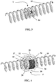
- the figure 3 presents a radiofrequency transponder 1 in a configuration where the electronic part 20 is located inside the radiating antenna 10.
- the geometric shape of the electronic part 20 is circumscribed in a cylinder whose diameter is less than or equal to the internal diameter 13 coil spring. The threading of the electronic part 20 into the radiating antenna 10 is thereby facilitated.
- the median plane 21 of the primary antenna is found substantially superimposed on the median plane 19 of the radiating antenna 10.
- the figure 4 presents a radiofrequency transponder 5 in a configuration where the electronic part 30 is located outside the radiating antenna 10.
- the geometric shape of the electronic part 30 has a cylindrical cavity 35 whose diameter is greater than or equal to the outer diameter 15 of the radiating antenna 10. The insertion of the radiating antenna 10 into the cylindrical cavity 35 of the electronic part is thus facilitated.
- the median plane of the primary antenna is located substantially in the median plane of the radiating antenna 10.
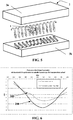
- the figure 5 presents an identification patch 2 comprising a radiofrequency transponder 1 embedded in a flexible mass 3 of electrically insulating elastomeric material represented by the plates 3a and 3b.
- the radiofrequency transponder 1 is in a configuration where the electronic part 20 is located inside the radiating antenna 10.
- the figure 6 is a graph of the electrical power transmitted by a radiofrequency transponder located inside a Michelin XINCITY brand pneumatic casing of size 275/70 R22.5 to a radiofrequency reader.
- the measurement protocol used corresponds to the ISO / IEC 18046-3 standard entitled “Identification Electromagnetic Field Threshold and Frequency Peaks”. The measurements were carried out for a wide frequency sweep and not punctually as usual.
- the x-axis represents the frequency of the communication signal.
- the ordinate axis is the electric power received by the radiofrequency reader expressed in decibels relative to the maximum electric power transmitted by a current radiofrequency transponder of the state of the art.
- the dotted curve 100 represents the response of a radiofrequency transponder according to the cited document.
- the continuous curve 200 represents the response of a transponder according to the invention for the same signal emitted by the radiofrequency reader.
- the gain remains of the order of at least one decibel over a frequency band widened around the communication frequency.
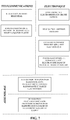
- the figure 7 is a block diagram of the method of manufacturing an identification patch 2 according to the invention.
- Obtaining the identification patch 2 requires the initial manufacture of a radiofrequency transponder 1, 5 according to the invention.
- the various chronological stages in the manufacture of the radiofrequency transponder 1, 5 then those of the identification patch 2 are identified.
- the steps related to the telecommunications or electronics trades are clearly delimited from those of the assembly which can be carried out by the tire manufacturer, for example for an application on pneumatic tires.
- the radiating antenna 10 is formed which will ensure the transmission and reception of radio waves with the radio frequency reader.
- the first step consists in plastically deforming the steel wire 12 with an external diameter of 200 micrometers to form a helical spring with a helical pitch of 1.5 mm using suitable industrial means such as than a turn to wind the springs.
- a continuous spring is thus obtained whose external diameter 15 is of the order of 1.6 millimeters which is small compared to the length 17 of the final radiating antenna of between 40 to 60 millimeters as desired. , for example 50 millimeters.
- a heat treatment can be applied after this step of plastic deformation, heating above 200 ° Celsius for at least 30 minutes, in order to relax the pre-stresses in the helical spring thus formed.
- the second step consists in cutting the coil spring by laser cutting to the desired length corresponding to the half wavelength of the frequency of the radioelectric communication signals, taking into account the propagation speed of these waves in an elastomeric medium, i.e. approximately 50 millimeters.
- the mechanical part thus obtained represents the radiating antenna 10 according to the invention.
- the electronic part 20 of the radiofrequency transponder 1 is produced, which will ensure the interrogation and the response from the electronic chip 22 to the radiating antenna 10.
- the transmission of information between the radiating antenna 10 and the part electronics 20 is produced by electromagnetic coupling using a primary antenna 24.
- This electronic device encapsulated in the rigid mass 29, is composed on the one hand of an electronic chip 22 and on the other hand of a primary antenna 24.
- a first embodiment of this electronic device is presented at figure 3 in the configuration where the electronic part 20 is intended to be located inside the radiating antenna 10.
- the leadframe method is used in terms of electromechanical support to the primary antenna 24 and to the electronic chip 22 representing the equivalent of a printed circuit 26. This method is particularly well suited in this configuration because of its ease of miniaturization.
- the first step is to compose the electronic card.
- the electronic chip 22 is fixed, first of all, on the grid or leadframe using a conductive glue, for example H20E from the Tedella brand.
- the wiring of the chip is carried out by the technique of wire-bonding, that is to say the realization of an electrical bridge through, for example, 28 gold wires with a diameter of 20 micrometers between the electronic chip 22 and the printed circuit 26 represented by the grid. It is then possible to measure the electrical impedance of the electronic card at the fixing points of the primary antenna 24 on the grid using a suitable electrical device such as an impedance meter.
- the second step consists in making the primary antenna 24.
- this antenna will consist of a coil with circular turns built directly on the grid (lead frame) by the cabling technology of wire (wire-bonding).
- Another variant of the primary antenna not shown, consists in creating an antenna using two copper wire segments connected to the electronic board by means of a metal soldering technique used in the electronics industry and oriented in opposite directions to form a dipole.
- a gold wire of 20 micrometer in diameter will be used, one could also have used aluminum wire or palladium copper, to make the half-turns of the coil on the reverse side of the grille.
- the diameter of the half turn is 400 micrometers, we use the ultrasound technique classic in the semiconductor industry to electrically connect the gold threads on the grid. Then on the front face of the grid, the other half turn is made in order to obtain a cylindrical coil with 15 turns of diameter 400 micrometers.
- the number of turns of the primary antenna 24 is determined so that the electrical impedance of the primary antenna 24 is matched to the electrical impedance of the electronic card comprising at least the printed circuit 26 represented by the grid and the electronic chip 22.
- the electrical impedance of electronic chip 22 alone is a complex number having a value for example of (10-j * 150) ohms.
- a coil of 15 turns with a diameter of 400 micrometers corresponds to a good adaptation of the electrical impedance of the electronic card built on a copper connection grid.
- the last step in producing the electronic part 20 consists in encapsulating the printed circuit 26, the components which are connected to it and the primary antenna 24 using a high temperature epoxy resin, in a rigid mass 29.
- a rigid mass 29 For this, , the globtop technology well known to a person skilled in the art is used.
- the rigid mass 29 forms a capsule protecting the electronic card of the radiofrequency transponder 1.
- the first step is to make the primary antenna 24 using a copper wire. 180 micrometer covered with an electrically insulating thermoplastic sheath. This wire is wound on a rigid and electrically insulating tubular core by making a coil of ten turns with an outer diameter of 1 millimeter with a helix pitch of 0.2 millimeter ending in two uncoated ends. It is then possible to evaluate the real peripheral surface s of the primary antenna 24 using the diameter of the copper wire, the external diameter of the antenna, the helix pitch and the total number of turns. In this case, the radius of the helical surface is 500 micrometers since the primary antenna 24 is located inside the radiating antenna 10.
- the electronic card is produced using a flexible support.
- the electronic chip 22 is fixed using a conductive adhesive of the ACP type (acronym Anisotropic Conductive Paste) which does not require wiring. between chip 22 and electronic card.
- the electronic chip 22 is fixed using a non-conductive adhesive for mounting electronic components.
- the wiring of the chip 22 to the electronic board is carried out by the wire-bonding technique, that is to say the production of an electrical bridge by means, for example, of gold wires 28 with a diameter of 20 micrometers. positioned between the electronic chip 22 and the flexible support representing the printed circuit 26 ..
- the two uncoated ends of the primary antenna 24 are connected to the printed circuit 26 by using a conductive glue, for example H20E from the Tedella brand.
- the electronic card and the uncoated terminations of the primary antenna 24 are covered with a rigid and electrically insulating material of the high temperature epoxy resin type using the globtop technique well known to those skilled in the art.
- an electronic chip 32 and possibly additional components are connected to a flexible support constituting the printed circuit 36 (translation into English “flex PCB”) and possibly additional components in order to compose the card.
- the electrical impedance of the electronic card is measured by means of suitable electrical equipment such as an impedance meter at the terminals of the copper connections on the top face of the flexible printed circuit where the primary antenna will be connected.
- suitable electrical equipment such as an impedance meter at the terminals of the copper connections on the top face of the flexible printed circuit where the primary antenna will be connected.
- Each of the copper connections has a central cavity extending through the thickness of the flexible backing to the underside of the backing.
- the primary antenna 34 is made around a tube 37 of electrically insulating resin, the internal diameter of which, delimiting the cylindrical cavity 35 of the electronic part, is greater than or equal to the external diameter 15 of the helical spring of the the radiating antenna 10 is of the order of 1.3 millimeters.
- the thickness of this tube is about 0.5 millimeter.
- Each end of the tube has an extra thickness of 0.5 millimeter constituting a rim 38 of width less than or equal to 0.5 millimeter.
- a copper wire with a diameter of 200 micrometers is wound on the outer face of the tube 37, between the two flanges 38, in order to constitute a given number of turns which makes it possible to produce a primary antenna 34 in the form of a cylindrical coil having an electrical impedance matched to the impedance of the electronic card to which it will be electrically connected.
- the flexible printed circuit 36 of the electronic card produced in the first step is fixed on the edges 38 of the tube 37 in insulating resin using a conductive adhesive of the H20E type from the Tedella brand.
- a conductive adhesive of the H20E type from the Tedella brand First, each of the ends has been inserted. of the copper wire of the primary antenna 34 between a flange 38 of the tube 37 and the flexible printed circuit 36, the two parts to be assembled.
- an electrical connection is made by brazing a conductive metal of the copper type through the cavity passing through the flexible printed circuit 36 at the level of the copper connections.
- the electronic device is coated with a rigid electrically insulating mass 39 to a thickness of at least 1 millimeter in order to protect the electronic card and the primary antenna 34 from various chemical attacks and to mechanically protect the electrical connections.
- An injection technique is used consisting of positioning the electronic device in a mold. However, to preserve the cylindrical cavity 35 of the initial resin tube, a flexible and air-impermeable elastomeric membrane is placed passing through the cylindrical cavity 35 which is pressurized to seal this cylindrical cavity 35 against the propagation of the gas. protective resin.
- the third phase of the production of the radio frequency transponder 1 or 5 consists in assembling the radiating antenna 10 produced in the first step to the electronic part 20 or 30 produced in the second step.
- the electronic part 20 is entered in a cylinder with a diameter less than or equal to the internal diameter 13 of the radiating antenna 10 carried out in the first step, i.e. of the order of a millimeter.
- the electronic part 20 is inserted inside the radiating antenna 10 by positioning the axis of symmetry 23 of the primary antenna in the direction of the axis of revolution 11 of the radiating antenna 10. In addition, we pushes the electronic part 20 into the radiating antenna 10 until the median plane 21 of the primary antenna coincides with the median plane 19 of the radiating antenna. Then the electronic part 20 is released from the long nose pliers and the pliers are gently withdrawn from the inside of the radiating antenna 10.
- Self-centering, parallelism of the axes and relative position of the median planes between the radiating antenna 10 and the primary antenna 24, is thus achieved favorable to a quality inductive coupling between the two antennas.
- the assembly thus formed represents a radiofrequency transponder 1 according to the invention.
- the outside of the electronic part 30 produced in the second phase is fixed using, for example, a vice.
- the radiating antenna 10 produced during the first phase is grasped using long nose pliers by one of its ends.
- the other end of the radiating antenna 10 is then inserted into the cylindrical cavity 35 of the electronic part 30 and the radiating antenna 10 is guided with the aid of the long nose pliers through the cylindrical cavity 35 to that the median plane 19 of the radiating antenna 10 coincides with the median plane of the primary antenna 34.
- the radiating antenna 10 is then released by opening the ends of the long nose pliers.
- the assembly thus formed represents a radio frequency transponder 5 according to the invention.
- the last step is to obtain an identification patch 2 to facilitate application of the radiofrequency transponder 1 or 5 in objects to be identified which are partly constituted by elastomer mixtures.
- the procedure is as follows for this step.
- the radiofrequency transponder 1 or 5 formed in the previous step is placed at the center of a flexible mass 3.
- the radiofrequency transponder 1 is sandwiched between two plates 3a and 3b of green elastomer material of dimensions a function of that of the radiofrequency transponder 1 and a thickness of, for example, between 2 and 5 millimeters.
- the longitudinal direction of the plates corresponds to the axis of the radiating antenna 10.
- the assembly is located beforehand on the internal face of a metal die of a press tool of dimension adapted to the volume of elastomeric mass.
- a compressive force is applied by means of a press tool, for example a pneumatic uni-axial press, to the assembly in order to form a compact geometry having an axis of symmetry, of length for example of 60 millimeters, inscribed in a cylinder with a diameter of approximately 20 millimeters corresponding to an identification patch 2 of the radiofrequency transponder 1 or 5 according to the invention.
- a press tool for example a pneumatic uni-axial press
- Radiofrequency transponder 1, 5 within a mass of one or more elastomer mixtures, for example the extrusion or injection process.
- adhesion promoters well known to those skilled in the art are employed between the rigid mass 29, 39 of high temperature epoxy resin encapsulating the electronic part 20, 30 of the radiofrequency transponder 1.5 and the mixture.
- elastomer of identification patch 2 It can improve the endurance of radio frequency transponder in service.
- a radiofrequency transponder 1, 5 for an object to be identified such as a pneumatic tire can be carried out according to at least two embodiments.
- the radiofrequency transponder 1, 5 or the identification patch 2 made of a raw elastomeric mixture in the blank of the tire when making the tire.
- the transponder or the identification patch 2 is geometrically placed between the various elastomeric components of the green blank of the pneumatic tire. Ideally, it is placed in a geographical area undergoing acceptable levels of deformation so that the radiating antenna 10 is not plastically deformed.
- the blank undergoes the various manufacturing phases of the tire, including curing in an autoclave vulcanizing the various elastomer mixtures and making the transponder or the identification patch of the tire thus produced integral.
- the radiofrequency transponder 1, 5 is then ready for use.
- Another preferred embodiment consists in fixing the elastomeric structure of the identification patch 2 by crosslinking or vulcanization during a step subsequent to the manufacture of the identification patch 2.
- the device obtained as a result of this operation is fixed. on a reception area of the pneumatic tire by a conventional elastomer / elastomer fixing technique known to those skilled in the art such as for example the adhesion by cold crosslinking of a layer of bonding rubber on the inner rubber of the tire tire
- the radiofrequency transponder 1, 5 of the tire is then ready for use.
Landscapes
- Engineering & Computer Science (AREA)
- Mechanical Engineering (AREA)
- Computer Networks & Wireless Communication (AREA)
- Signal Processing (AREA)
- Computer Hardware Design (AREA)
- Microelectronics & Electronic Packaging (AREA)
- Physics & Mathematics (AREA)
- General Physics & Mathematics (AREA)
- Theoretical Computer Science (AREA)
- Support Of Aerials (AREA)
- Details Of Aerials (AREA)
- Radar Systems Or Details Thereof (AREA)
Claims (15)
- Hochfrequenztransponder (1, 5), der dazu bestimmt ist, in ein zu kennzeichnendes Objekt, das aus einer Elastomermischung oder -zusammensetzung besteht, integriert zu werden, umfassend:- einen elektronischen Chip (22, 32),- eine abstrahlende Antenne (10), die mit einem Hochfrequenz-Lesegerät kommuniziert, das von jeglicher gedruckten Schaltung getrennt ist,dadurch gekennzeichnet, dass der Hochfrequenztransponder (1, 5) zudem eine Primärantenne (24, 34) umfasst, die elektrisch mit dem elektronischen Chip (22, 32) verbunden ist und die eine Spule mit mindestens einer Windung ist,dass die Primärantenne (24, 34) induktiv mit der abstrahlenden Antenne (10) gekoppelt ist, dass die abstrahlende Antenne (10) eine Dipolantenne ist, die aus einer einsträngigen Spiralfeder besteht, und dass die Primärantenne (24, 34), die eine Symmetrieachse (23) aufweist, in einem Zylinder begrenzt ist, dessen Drehachse parallel zur Symmetrieachse (23) der Primärantenne (24, 34) ist und dessen Durchmesser größer oder gleich dem Drittel des Innendurchmessers (13) der Spiralfeder der abstrahlenden Antenne (10) ist.
- Hochfrequenztransponder (1, 5) nach Anspruch 1, wobei die Primärantenne (24, 34) eine Symmetrieachse (23) aufweist, wobei die Symmetrieachse (23) der Primärantenne (24, 34) und die Drehachse (11) der abstrahlenden Antenne (10) im Wesentlichen parallel sind.
- Hochfrequenztransponder (1, 5) nach einem der Ansprüche 1 bis 2, wobei die Mittelebene (21) der Spule der Primärantenne (24, 34) im Wesentlichen der Mittelebene (19) der Spiralfeder der abstrahlenden Antenne (10) überlagert ist.
- Hochfrequenztransponder (1, 5) nach einem der vorhergehenden Ansprüche, wobei die Primärantenne (24, 34) mit den Anschlüssen einer elektronischen Platine verbunden ist, die den elektronischen Chip (22, 32) umfasst, und die elektrische Impedanz der Primärantenne (24, 34) der elektrischen Impedanz der elektronischen Platine des Hochfrequenztransponders (1, 5) angepasst ist.
- Hochfrequenztransponder (1, 5) nach einem der Ansprüche 1 bis 4, wobei der elektronische Chip (22, 32) und mindestens ein Teil der Primärantenne (24, 34) in eine starre und elektrisch isolierende Masse (29, 39) eingegossen sind, um den elektronischen Teil (20, 30) des Hochfrequenztransponders (1, 5) zu bilden.
- Hochfrequenztransponder (1, 5) nach Anspruch 5, wobei mindestens ein Teil der Primärantenne (24, 34), der nicht in die starre Masse (29, 39) eingegossen ist, mit einem elektrisch isolierenden Material verkleidet ist.
- Hochfrequenztransponder (1, 5) nach einem der Ansprüche 5 bis 6, wobei sich der elektronische Teil (20) des Hochfrequenztransponders (1) im Inneren der abstrahlenden Antenne (10) befindet.
- Hochfrequenztransponder (1, 5) nach Anspruch 7, wobei die Geometrie des elektronischen Teils (20) des Hochfrequenztransponders (1) in einem Zylinder enthalten ist, dessen Durchmesser kleiner oder gleich dem Innendurchmesser (13) der abstrahlenden Antenne (10) ist und dessen Drehachse parallel oder koaxial zur Symmetrieachse (23) der Primärantenne (24) ist.
- Hochfrequenztransponder (5) nach einem der Ansprüche 5 bis 6, wobei sich der elektronische Teil (30) des Hochfrequenztransponders (5) außerhalb der abstrahlenden Antenne (10) befindet.
- Hochfrequenztransponder (5) nach Anspruch 9, wobei der Durchmesser des Kreises, der in der Primärantenne (34) enthalten ist, kleiner als der dreifache Außendurchmesser (15) der abstrahlenden Antenne (10) ist.
- Hochfrequenztransponder (1, 5) nach einem der Ansprüche 1 bis 10, wobei der elektronische Chip (22, 32) elektrisch mit einer gedruckten Schaltung (26, 36) verbunden ist, um die elektronische Platine zu bilden und die gedruckte Schaltung (26, 36) eine oder mehrere zusätzliche passive oder aktive elektronische Bauelemente umfasst.
- Kennzeichnungspatch (2), umfassend einen Hochfrequenztransponder (1, 5) nach einem der vorhergehenden Ansprüche, wobei der Hochfrequenztransponder (1, 5) in mindestens eine weiche und elektrisch isolierende Elastomermischung (3) eingegossen ist.
- Reifenmantel, umfassend ein Kennzeichnungspatch (2) nach Anspruch 12, wobei das Kennzeichnungspatch (2) im Reifenmantel eingebettet ist.
- Verfahren zur Herstellung eines Hochfrequenztransponders (1, 5), wobei:- eine Spiralfeder mit einer Abmessung hergestellt wird, die der Kommunikationsfrequenz des Funksignals des Hochfrequenztransponders (1) angepasst ist, um die abstrahlende Antenne (10) des Hochfrequenztransponders (1) zu bilden,- ein elektronischer Chip (22, 32) auf einer gedruckten Schaltung (26, 36) angeschlossen wird, um eine elektronische Platine zu bilden,- mithilfe eines leitfähigen Drahts eine Primärantenne (24, 34) hergestellt wird,- die Primärantenne (24, 34) mit der elektronischen Platine verbunden wird,- mindestens ein Teil der Primärantenne (24, 34) und die elektronische Platine in eine starre und elektrisch isolierende Masse (29, 39) wie etwa wärmehärtbares Harz eingegossen wird, um den elektronischen Teil (20, 30) des Hochfrequenztransponders (1, 5) zu bilden,- durch einfaches Einschieben der elektronische Teil (20, 30) und die abstrahlende Antenne (10) so positioniert werden, dass die Achsen der beiden Antennen im Wesentlichen parallel sind und die Mittelebenen der beiden Antennen im Wesentlichen überlagert sind, da die Primärantenne (24, 34) eine Symmetrieachse (23) und eine Mittelebene (21) aufweist und die abstrahlende Antenne (10) eine Drehachse (11) und eine Mittelebene (19) aufweist.
- Verfahren zur Herstellung eines Kennzeichnungspatches (2), wobei ein Hochfrequenztransponder (1, 5) nach einem der Ansprüche 1 bis 11 nach Anspruch 14 hergestellt wird, wobei der Hochfrequenztransponder (1, 5) durch ein Einspritz-, Extrusions- oder Kompressionsverfahren in eine Masse von mindestens einer weichen und elektrisch isolierenden Elastomermischung (3) eingebettet wird.
Applications Claiming Priority (2)
| Application Number | Priority Date | Filing Date | Title |
|---|---|---|---|
| FR1555048A FR3037200B1 (fr) | 2015-06-03 | 2015-06-03 | Transpondeur radiofrequence pour pneumatique |
| PCT/EP2016/062694 WO2016193457A1 (fr) | 2015-06-03 | 2016-06-03 | Transpondeur radiofrequence pour pneumatique |
Publications (2)
| Publication Number | Publication Date |
|---|---|
| EP3304748A1 EP3304748A1 (de) | 2018-04-11 |
| EP3304748B1 true EP3304748B1 (de) | 2021-10-06 |
Family
ID=54478101
Family Applications (1)
| Application Number | Title | Priority Date | Filing Date |
|---|---|---|---|
| EP16726612.1A Active EP3304748B1 (de) | 2015-06-03 | 2016-06-03 | Hochfrequenztransponder für einen reifen |
Country Status (5)
| Country | Link |
|---|---|
| US (1) | US10339435B2 (de) |
| EP (1) | EP3304748B1 (de) |
| CN (1) | CN107683214B (de) |
| FR (1) | FR3037200B1 (de) |
| WO (1) | WO2016193457A1 (de) |
Families Citing this family (46)
| Publication number | Priority date | Publication date | Assignee | Title |
|---|---|---|---|---|
| US20080117027A1 (en) * | 2006-11-16 | 2008-05-22 | Zih Corporation | Systems, methods, and associated rfid antennas for processing a plurality of transponders |
| CN107851900B (zh) * | 2015-07-17 | 2020-11-10 | 索尼公司 | 天线装置和模块装置 |
| FR3041285B1 (fr) | 2015-09-18 | 2017-10-27 | Michelin & Cie | Pneumatique possedant un transpondeur passif et procede de communication d'un tel pneumatique |
| FR3059606A1 (fr) | 2016-12-05 | 2018-06-08 | Compagnie Generale Des Etablissements Michelin | Module de communication radiofrequence pour pneumatique |
| FR3059607A1 (fr) | 2016-12-05 | 2018-06-08 | Compagnie Generale Des Etablissements Michelin | Module de communication radiofrequence pour pneumatique |
| FR3059592A1 (fr) | 2016-12-05 | 2018-06-08 | Compagnie Generale Des Etablissements Michelin | Procede de fabrication d'un patch equipe d'un transpondeur radiofrequence et pneumatique comportant un tel patch |
| FR3059604A1 (fr) * | 2016-12-05 | 2018-06-08 | Compagnie Generale Des Etablissements Michelin | Enveloppe pneumatique equipee d'un organe electronique |
| FR3059605A1 (fr) | 2016-12-05 | 2018-06-08 | Compagnie Generale Des Etablissements Michelin | Enveloppe pneumatique equipee d''un organe electronique |
| FR3059603A1 (fr) | 2016-12-07 | 2018-06-08 | Compagnie Generale Des Etablissements Michelin | Pneumatique adapte pour roulage a plat equipe d’un organe electronique |
| FR3067976B1 (fr) * | 2017-06-22 | 2019-07-26 | Compagnie Generale Des Etablissements Michelin | Pneumatique adapte pour roulage a plat equipe d'un organe electronique |
| FR3067975B1 (fr) * | 2017-06-22 | 2019-07-26 | Compagnie Generale Des Etablissements Michelin | Pneumatique adapte pour roulage a plat equipe d'un organe electronique |
| DE102017006450B4 (de) * | 2017-07-07 | 2019-05-23 | Ses Rfid Solutions Gmbh | RFID-Transponder für eine kontaktlose Kommunikation mit Plastikgehäuse |
| DE102017216043A1 (de) * | 2017-09-12 | 2019-03-14 | Robert Bosch Gmbh | System, umfassend einen metallischen Körper und eine Sensorvorrichtung mit einer optimierten Antenneneinheit |
| FR3073995B1 (fr) | 2017-11-17 | 2021-01-08 | Continental Automotive France | Systeme d'au moins deux unites emettrices et/ou receptrices reliees a une antenne commune |
| DE102018200103A1 (de) | 2018-01-05 | 2019-07-11 | Continental Reifen Deutschland Gmbh | Reifenbauteil für einen Reifenrohling |
| EP3762243B1 (de) * | 2018-03-07 | 2022-05-04 | Compagnie Generale Des Etablissements Michelin | Reifen mit einem funkfrequenzkommunikationsmodul |
| WO2019180357A1 (fr) * | 2018-03-20 | 2019-09-26 | Compagnie Generale Des Etablissements Michelin | Pneumatique poids-lourd equipe d'un module de communication radiofrequence |
| WO2019180358A1 (fr) * | 2018-03-22 | 2019-09-26 | Compagnie Generale Des Etablissements Michelin | Pneumatique poids-lourd equipe d'un module de communication radiofrequence |
| US11295193B2 (en) * | 2018-03-30 | 2022-04-05 | Compagnie Generale Des Etablissements Michelin | Radiofrequency transponder for tire |
| EP3774401B1 (de) | 2018-03-30 | 2022-10-05 | Compagnie Generale Des Etablissements Michelin | Funktransponder für reifen |
| EP3774400B1 (de) * | 2018-03-30 | 2022-05-18 | Compagnie Generale Des Etablissements Michelin | Funktransponder für einen reifen |
| IT201800004925A1 (it) | 2018-04-27 | 2019-10-27 | Pneumatico provvisto di un transponder | |
| IT201800004917A1 (it) * | 2018-04-27 | 2019-10-27 | Pneumatico provvisto di un transponder | |
| WO2019220064A2 (fr) * | 2018-05-17 | 2019-11-21 | Compagnie Generale Des Etablissements Michelin | Pneumatique poids-lourd equipe d'un module de communication radiofrequence |
| WO2019220063A2 (fr) | 2018-05-17 | 2019-11-21 | Compagnie Generale Des Etablissements Michelin | Procede de fabrication d'un pneumatique equipe d'un module de communication radiofrequence |
| FR3081774B1 (fr) * | 2018-05-29 | 2020-08-07 | Michelin & Cie | Enveloppe pneumatique equipee d'un systeme de mesure et methode de communication d'un tel assemblage |
| DE102018209154A1 (de) * | 2018-06-08 | 2019-12-12 | Continental Reifen Deutschland Gmbh | Elektromagnetische Sende- und Empfangsvorrichtung |
| JP6582105B1 (ja) | 2018-10-03 | 2019-09-25 | Toyo Tire株式会社 | タイヤの製造方法 |
| DE102018220562A1 (de) | 2018-11-29 | 2020-06-04 | Continental Reifen Deutschland Gmbh | Fahrzeugreifen |
| IT201900002337A1 (it) * | 2019-02-18 | 2020-08-18 | Bridgestone Europe Nv Sa | Dispositivo rfid perfezionato per pneumatici |
| FR3101170B1 (fr) | 2019-09-25 | 2022-08-05 | Michelin & Cie | pneumatique EQUIPE d’un Transpondeur radiofréquence |
| FR3101171B1 (fr) | 2019-09-25 | 2022-08-05 | Michelin & Cie | pneumatique EQUIPE d’un Transpondeur radiofréquence |
| FR3101019B1 (fr) * | 2019-09-25 | 2022-12-16 | Michelin & Cie | pneumatique EQUIPE d’un Transpondeur radiofréquence |
| FR3104068B1 (fr) | 2019-12-04 | 2024-03-08 | Michelin & Cie | Pneumatique équipé d’un transpondeur radiofréquence |
| FR3104069B1 (fr) | 2019-12-04 | 2024-03-29 | Michelin & Cie | Pneumatique equipe d’un transpondeur radiofrequence |
| EP4081946B1 (de) * | 2019-12-28 | 2024-06-19 | Avery Dennison Retail Information Services LLC | Rfid-systeme für reifen |
| DE102020206803A1 (de) | 2020-05-29 | 2021-12-02 | Fraunhofer-Gesellschaft zur Förderung der angewandten Forschung eingetragener Verein | Elektrische Komponente für das Verfahren zur Herstellung derselben |
| CH717620A9 (de) | 2020-07-07 | 2022-02-28 | Daetwyler Schweiz Ag | Fluidüberwachungssystem zum Überwachen eines Vorliegens oder eines Zustands eines Fluids unter Verwendung seiner Permittivität und das Verfahren dazu. |
| CN115812205A (zh) * | 2020-07-07 | 2023-03-17 | 德特威勒瑞士有限公司 | 具有集成传感器模块的弹性传感器部件 |
| CN116075827A (zh) * | 2020-09-08 | 2023-05-05 | 尖能株式会社 | 带rfid标签的安装部件、带rfid标签的安装部件的制造方法、带rfid标签的安装部件的头部及rfid标签装配单元 |
| WO2022236472A1 (en) * | 2021-05-08 | 2022-11-17 | Confidex Oy | Rfid transponder for a tyre |
| JP7262563B1 (ja) * | 2021-12-24 | 2023-04-21 | 横浜ゴム株式会社 | ソリッドタイヤ及びその製造方法 |
| IT202200003290A1 (it) | 2022-02-22 | 2023-08-22 | Pearfid Soc A Responsabilita Limitata Semplificata | Metodo di realizzazione di dispositivi a radiofrequenza |
| DE102022210359A1 (de) * | 2022-09-29 | 2024-04-04 | Contitech Techno-Chemie Gmbh | Funktransponder |
| WO2024147023A1 (en) * | 2023-01-04 | 2024-07-11 | Linxens Holding | Ultra-high frequency antenna device, ultra-high frequency antenna assembly, device method of forming such an antenna device, and support body material supply |
| JP7364820B1 (ja) | 2023-06-19 | 2023-10-18 | マルホ発條工業株式会社 | コイル付きモジュール製造装置およびコイル付きモジュール製造方法 |
Family Cites Families (11)
| Publication number | Priority date | Publication date | Assignee | Title |
|---|---|---|---|---|
| US5196845A (en) * | 1988-10-24 | 1993-03-23 | Compagnie Generale Des Etablissements Michelin | Antenna for tire monitoring device |
| WO2006118011A1 (ja) * | 2005-04-26 | 2006-11-09 | Sanyo Electric Co., Ltd. | タイヤセンサシステム及びこれに用いるタイヤ |
| KR20080046816A (ko) * | 2006-11-23 | 2008-05-28 | 한국타이어 주식회사 | 타이어 내에 장착되는 rfid 태그 구조 |
| BRPI0822605B1 (pt) | 2008-04-29 | 2019-04-02 | Compagnie Generale Des Etablissements Michelin | Dispositivo de identificação por radiofrequência, e, método para montagem de um dispositivo de identificação por radiofrequência. |
| FR2937284B1 (fr) * | 2008-10-20 | 2010-11-19 | Michelin Soc Tech | Organe pour pneumatique et pneumatique instrumente |
| JP5604593B2 (ja) * | 2010-08-30 | 2014-10-08 | コンパニー ゼネラール デ エタブリッスマン ミシュラン | バネ型rfidボード |
| JP5716891B2 (ja) * | 2010-11-10 | 2015-05-13 | 横浜ゴム株式会社 | 情報取得装置 |
| FR2983609B1 (fr) * | 2011-12-02 | 2014-02-07 | Michelin Soc Tech | Ensemble electronique destine a etre integre dans un pneumatique |
| FR3013907B1 (fr) | 2013-11-27 | 2016-01-01 | Michelin & Cie | Systeme de lecture dynamique de donnees de transpondeurs |
| FR3013870B1 (fr) | 2013-11-27 | 2016-01-01 | Michelin & Cie | Systeme de lecture dynamique de donnees de transpondeurs |
| FR3029832B1 (fr) | 2014-12-15 | 2017-10-20 | Michelin & Cie | Procede de pose de support pour module electronique de pneumatique |
-
2015
- 2015-06-03 FR FR1555048A patent/FR3037200B1/fr not_active Expired - Fee Related
-
2016
- 2016-06-03 EP EP16726612.1A patent/EP3304748B1/de active Active
- 2016-06-03 US US15/578,531 patent/US10339435B2/en active Active
- 2016-06-03 CN CN201680032233.7A patent/CN107683214B/zh active Active
- 2016-06-03 WO PCT/EP2016/062694 patent/WO2016193457A1/fr not_active Ceased
Also Published As
| Publication number | Publication date |
|---|---|
| US20180174015A1 (en) | 2018-06-21 |
| FR3037200B1 (fr) | 2017-05-26 |
| EP3304748A1 (de) | 2018-04-11 |
| WO2016193457A1 (fr) | 2016-12-08 |
| US10339435B2 (en) | 2019-07-02 |
| CN107683214A (zh) | 2018-02-09 |
| CN107683214B (zh) | 2019-12-13 |
| FR3037200A1 (fr) | 2016-12-09 |
Similar Documents
| Publication | Publication Date | Title |
|---|---|---|
| EP3304748B1 (de) | Hochfrequenztransponder für einen reifen | |
| EP3774401B1 (de) | Funktransponder für reifen | |
| EP3774402B1 (de) | Funktransponder für einen reifen | |
| EP3548314B1 (de) | Mit einem elektronischen element ausgestatteter luftreifen | |
| EP3548313B1 (de) | Mit einem elektronischen element ausgestatteter luftreifen | |
| EP3548312B1 (de) | Radiofrequenz-kommunikationsmodul für einen reifen | |
| EP3548316B1 (de) | Funkmodul für einen reifen | |
| EP3613076B1 (de) | Hochfrequenz sende- und empfangsvorrichtung | |
| EP4035073A1 (de) | Reifen, der einen radiofrequenz-transponder umfasst | |
| EP4035075A1 (de) | Reifen, der einen radiofrequenz-transponder umfasst | |
| EP4035074A1 (de) | Reifen, der einen radiofrequenz-transponder umfasst | |
| EP3774400B1 (de) | Funktransponder für einen reifen | |
| WO2019229389A1 (fr) | Enveloppe pneumatique equipee d'un systeme de mesure et methode de communication d'un tel assemblage | |
| EP3701589B1 (de) | Parametermesssystem für eine montierte anordnung | |
| EP2471028B1 (de) | Herstellungsverfahren für eine vorrichtung mit einer rfid-schaltung,und entsprechende vorrichtung |
Legal Events
| Date | Code | Title | Description |
|---|---|---|---|
| STAA | Information on the status of an ep patent application or granted ep patent |
Free format text: STATUS: THE INTERNATIONAL PUBLICATION HAS BEEN MADE |
|
| PUAI | Public reference made under article 153(3) epc to a published international application that has entered the european phase |
Free format text: ORIGINAL CODE: 0009012 |
|
| STAA | Information on the status of an ep patent application or granted ep patent |
Free format text: STATUS: REQUEST FOR EXAMINATION WAS MADE |
|
| 17P | Request for examination filed |
Effective date: 20180103 |
|
| AK | Designated contracting states |
Kind code of ref document: A1 Designated state(s): AL AT BE BG CH CY CZ DE DK EE ES FI FR GB GR HR HU IE IS IT LI LT LU LV MC MK MT NL NO PL PT RO RS SE SI SK SM TR |
|
| AX | Request for extension of the european patent |
Extension state: BA ME |
|
| DAV | Request for validation of the european patent (deleted) | ||
| DAX | Request for extension of the european patent (deleted) | ||
| GRAP | Despatch of communication of intention to grant a patent |
Free format text: ORIGINAL CODE: EPIDOSNIGR1 |
|
| STAA | Information on the status of an ep patent application or granted ep patent |
Free format text: STATUS: GRANT OF PATENT IS INTENDED |
|
| INTG | Intention to grant announced |
Effective date: 20210517 |
|
| RAP3 | Party data changed (applicant data changed or rights of an application transferred) |
Owner name: COMPAGNIE GENERALE DES ETABLISSEMENTS MICHELIN |
|
| RAP3 | Party data changed (applicant data changed or rights of an application transferred) |
Owner name: COMPAGNIE GENERALE DES ETABLISSEMENTS MICHELIN |
|
| GRAS | Grant fee paid |
Free format text: ORIGINAL CODE: EPIDOSNIGR3 |
|
| GRAA | (expected) grant |
Free format text: ORIGINAL CODE: 0009210 |
|
| STAA | Information on the status of an ep patent application or granted ep patent |
Free format text: STATUS: THE PATENT HAS BEEN GRANTED |
|
| AK | Designated contracting states |
Kind code of ref document: B1 Designated state(s): AL AT BE BG CH CY CZ DE DK EE ES FI FR GB GR HR HU IE IS IT LI LT LU LV MC MK MT NL NO PL PT RO RS SE SI SK SM TR |
|
| REG | Reference to a national code |
Ref country code: GB Ref legal event code: FG4D Free format text: NOT ENGLISH |
|
| REG | Reference to a national code |
Ref country code: CH Ref legal event code: EP Ref country code: AT Ref legal event code: REF Ref document number: 1437082 Country of ref document: AT Kind code of ref document: T Effective date: 20211015 |
|
| REG | Reference to a national code |
Ref country code: IE Ref legal event code: FG4D Free format text: LANGUAGE OF EP DOCUMENT: FRENCH |
|
| REG | Reference to a national code |
Ref country code: DE Ref legal event code: R096 Ref document number: 602016064601 Country of ref document: DE |
|
| REG | Reference to a national code |
Ref country code: NL Ref legal event code: FP |
|
| REG | Reference to a national code |
Ref country code: LT Ref legal event code: MG9D |
|
| REG | Reference to a national code |
Ref country code: AT Ref legal event code: MK05 Ref document number: 1437082 Country of ref document: AT Kind code of ref document: T Effective date: 20211006 |
|
| PG25 | Lapsed in a contracting state [announced via postgrant information from national office to epo] |
Ref country code: RS Free format text: LAPSE BECAUSE OF FAILURE TO SUBMIT A TRANSLATION OF THE DESCRIPTION OR TO PAY THE FEE WITHIN THE PRESCRIBED TIME-LIMIT Effective date: 20211006 Ref country code: LT Free format text: LAPSE BECAUSE OF FAILURE TO SUBMIT A TRANSLATION OF THE DESCRIPTION OR TO PAY THE FEE WITHIN THE PRESCRIBED TIME-LIMIT Effective date: 20211006 Ref country code: FI Free format text: LAPSE BECAUSE OF FAILURE TO SUBMIT A TRANSLATION OF THE DESCRIPTION OR TO PAY THE FEE WITHIN THE PRESCRIBED TIME-LIMIT Effective date: 20211006 Ref country code: BG Free format text: LAPSE BECAUSE OF FAILURE TO SUBMIT A TRANSLATION OF THE DESCRIPTION OR TO PAY THE FEE WITHIN THE PRESCRIBED TIME-LIMIT Effective date: 20220106 Ref country code: AT Free format text: LAPSE BECAUSE OF FAILURE TO SUBMIT A TRANSLATION OF THE DESCRIPTION OR TO PAY THE FEE WITHIN THE PRESCRIBED TIME-LIMIT Effective date: 20211006 |
|
| PG25 | Lapsed in a contracting state [announced via postgrant information from national office to epo] |
Ref country code: IS Free format text: LAPSE BECAUSE OF FAILURE TO SUBMIT A TRANSLATION OF THE DESCRIPTION OR TO PAY THE FEE WITHIN THE PRESCRIBED TIME-LIMIT Effective date: 20220206 Ref country code: SE Free format text: LAPSE BECAUSE OF FAILURE TO SUBMIT A TRANSLATION OF THE DESCRIPTION OR TO PAY THE FEE WITHIN THE PRESCRIBED TIME-LIMIT Effective date: 20211006 Ref country code: PT Free format text: LAPSE BECAUSE OF FAILURE TO SUBMIT A TRANSLATION OF THE DESCRIPTION OR TO PAY THE FEE WITHIN THE PRESCRIBED TIME-LIMIT Effective date: 20220207 Ref country code: PL Free format text: LAPSE BECAUSE OF FAILURE TO SUBMIT A TRANSLATION OF THE DESCRIPTION OR TO PAY THE FEE WITHIN THE PRESCRIBED TIME-LIMIT Effective date: 20211006 Ref country code: NO Free format text: LAPSE BECAUSE OF FAILURE TO SUBMIT A TRANSLATION OF THE DESCRIPTION OR TO PAY THE FEE WITHIN THE PRESCRIBED TIME-LIMIT Effective date: 20220106 Ref country code: LV Free format text: LAPSE BECAUSE OF FAILURE TO SUBMIT A TRANSLATION OF THE DESCRIPTION OR TO PAY THE FEE WITHIN THE PRESCRIBED TIME-LIMIT Effective date: 20211006 Ref country code: HR Free format text: LAPSE BECAUSE OF FAILURE TO SUBMIT A TRANSLATION OF THE DESCRIPTION OR TO PAY THE FEE WITHIN THE PRESCRIBED TIME-LIMIT Effective date: 20211006 Ref country code: GR Free format text: LAPSE BECAUSE OF FAILURE TO SUBMIT A TRANSLATION OF THE DESCRIPTION OR TO PAY THE FEE WITHIN THE PRESCRIBED TIME-LIMIT Effective date: 20220107 Ref country code: ES Free format text: LAPSE BECAUSE OF FAILURE TO SUBMIT A TRANSLATION OF THE DESCRIPTION OR TO PAY THE FEE WITHIN THE PRESCRIBED TIME-LIMIT Effective date: 20211006 |
|
| REG | Reference to a national code |
Ref country code: DE Ref legal event code: R097 Ref document number: 602016064601 Country of ref document: DE |
|
| PG25 | Lapsed in a contracting state [announced via postgrant information from national office to epo] |
Ref country code: SM Free format text: LAPSE BECAUSE OF FAILURE TO SUBMIT A TRANSLATION OF THE DESCRIPTION OR TO PAY THE FEE WITHIN THE PRESCRIBED TIME-LIMIT Effective date: 20211006 Ref country code: SK Free format text: LAPSE BECAUSE OF FAILURE TO SUBMIT A TRANSLATION OF THE DESCRIPTION OR TO PAY THE FEE WITHIN THE PRESCRIBED TIME-LIMIT Effective date: 20211006 Ref country code: RO Free format text: LAPSE BECAUSE OF FAILURE TO SUBMIT A TRANSLATION OF THE DESCRIPTION OR TO PAY THE FEE WITHIN THE PRESCRIBED TIME-LIMIT Effective date: 20211006 Ref country code: EE Free format text: LAPSE BECAUSE OF FAILURE TO SUBMIT A TRANSLATION OF THE DESCRIPTION OR TO PAY THE FEE WITHIN THE PRESCRIBED TIME-LIMIT Effective date: 20211006 Ref country code: DK Free format text: LAPSE BECAUSE OF FAILURE TO SUBMIT A TRANSLATION OF THE DESCRIPTION OR TO PAY THE FEE WITHIN THE PRESCRIBED TIME-LIMIT Effective date: 20211006 Ref country code: CZ Free format text: LAPSE BECAUSE OF FAILURE TO SUBMIT A TRANSLATION OF THE DESCRIPTION OR TO PAY THE FEE WITHIN THE PRESCRIBED TIME-LIMIT Effective date: 20211006 |
|
| PLBE | No opposition filed within time limit |
Free format text: ORIGINAL CODE: 0009261 |
|
| STAA | Information on the status of an ep patent application or granted ep patent |
Free format text: STATUS: NO OPPOSITION FILED WITHIN TIME LIMIT |
|
| 26N | No opposition filed |
Effective date: 20220707 |
|
| PG25 | Lapsed in a contracting state [announced via postgrant information from national office to epo] |
Ref country code: AL Free format text: LAPSE BECAUSE OF FAILURE TO SUBMIT A TRANSLATION OF THE DESCRIPTION OR TO PAY THE FEE WITHIN THE PRESCRIBED TIME-LIMIT Effective date: 20211006 |
|
| PG25 | Lapsed in a contracting state [announced via postgrant information from national office to epo] |
Ref country code: SI Free format text: LAPSE BECAUSE OF FAILURE TO SUBMIT A TRANSLATION OF THE DESCRIPTION OR TO PAY THE FEE WITHIN THE PRESCRIBED TIME-LIMIT Effective date: 20211006 |
|
| PG25 | Lapsed in a contracting state [announced via postgrant information from national office to epo] |
Ref country code: MC Free format text: LAPSE BECAUSE OF FAILURE TO SUBMIT A TRANSLATION OF THE DESCRIPTION OR TO PAY THE FEE WITHIN THE PRESCRIBED TIME-LIMIT Effective date: 20211006 |
|
| REG | Reference to a national code |
Ref country code: CH Ref legal event code: PL |
|
| REG | Reference to a national code |
Ref country code: BE Ref legal event code: MM Effective date: 20220630 |
|
| GBPC | Gb: european patent ceased through non-payment of renewal fee |
Effective date: 20220603 |
|
| PG25 | Lapsed in a contracting state [announced via postgrant information from national office to epo] |
Ref country code: LU Free format text: LAPSE BECAUSE OF NON-PAYMENT OF DUE FEES Effective date: 20220603 Ref country code: LI Free format text: LAPSE BECAUSE OF NON-PAYMENT OF DUE FEES Effective date: 20220630 Ref country code: IE Free format text: LAPSE BECAUSE OF NON-PAYMENT OF DUE FEES Effective date: 20220603 Ref country code: CH Free format text: LAPSE BECAUSE OF NON-PAYMENT OF DUE FEES Effective date: 20220630 |
|
| PG25 | Lapsed in a contracting state [announced via postgrant information from national office to epo] |
Ref country code: IT Free format text: LAPSE BECAUSE OF FAILURE TO SUBMIT A TRANSLATION OF THE DESCRIPTION OR TO PAY THE FEE WITHIN THE PRESCRIBED TIME-LIMIT Effective date: 20211006 Ref country code: GB Free format text: LAPSE BECAUSE OF NON-PAYMENT OF DUE FEES Effective date: 20220603 Ref country code: BE Free format text: LAPSE BECAUSE OF NON-PAYMENT OF DUE FEES Effective date: 20220630 |
|
| PG25 | Lapsed in a contracting state [announced via postgrant information from national office to epo] |
Ref country code: HU Free format text: LAPSE BECAUSE OF FAILURE TO SUBMIT A TRANSLATION OF THE DESCRIPTION OR TO PAY THE FEE WITHIN THE PRESCRIBED TIME-LIMIT; INVALID AB INITIO Effective date: 20160603 |
|
| PG25 | Lapsed in a contracting state [announced via postgrant information from national office to epo] |
Ref country code: MK Free format text: LAPSE BECAUSE OF FAILURE TO SUBMIT A TRANSLATION OF THE DESCRIPTION OR TO PAY THE FEE WITHIN THE PRESCRIBED TIME-LIMIT Effective date: 20211006 Ref country code: CY Free format text: LAPSE BECAUSE OF FAILURE TO SUBMIT A TRANSLATION OF THE DESCRIPTION OR TO PAY THE FEE WITHIN THE PRESCRIBED TIME-LIMIT Effective date: 20211006 |
|
| PG25 | Lapsed in a contracting state [announced via postgrant information from national office to epo] |
Ref country code: MT Free format text: LAPSE BECAUSE OF FAILURE TO SUBMIT A TRANSLATION OF THE DESCRIPTION OR TO PAY THE FEE WITHIN THE PRESCRIBED TIME-LIMIT Effective date: 20211006 |
|
| PGFP | Annual fee paid to national office [announced via postgrant information from national office to epo] |
Ref country code: DE Payment date: 20250618 Year of fee payment: 10 |
|
| PGFP | Annual fee paid to national office [announced via postgrant information from national office to epo] |
Ref country code: NL Payment date: 20250618 Year of fee payment: 10 |
|
| PGFP | Annual fee paid to national office [announced via postgrant information from national office to epo] |
Ref country code: FR Payment date: 20250625 Year of fee payment: 10 |
|
| PG25 | Lapsed in a contracting state [announced via postgrant information from national office to epo] |
Ref country code: TR Free format text: LAPSE BECAUSE OF FAILURE TO SUBMIT A TRANSLATION OF THE DESCRIPTION OR TO PAY THE FEE WITHIN THE PRESCRIBED TIME-LIMIT Effective date: 20211006 |