EP3305460A1 - Appareil de soudage de fils, module de batterie fabriqué au moyen dudit appareil de soudage de fils et bloc-batterie comprenant ledit module de batterie - Google Patents
Appareil de soudage de fils, module de batterie fabriqué au moyen dudit appareil de soudage de fils et bloc-batterie comprenant ledit module de batterie Download PDFInfo
- Publication number
- EP3305460A1 EP3305460A1 EP17799535.4A EP17799535A EP3305460A1 EP 3305460 A1 EP3305460 A1 EP 3305460A1 EP 17799535 A EP17799535 A EP 17799535A EP 3305460 A1 EP3305460 A1 EP 3305460A1
- Authority
- EP
- European Patent Office
- Prior art keywords
- welding
- battery
- lead
- electrode leads
- electrode
- Prior art date
- Legal status (The legal status is an assumption and is not a legal conclusion. Google has not performed a legal analysis and makes no representation as to the accuracy of the status listed.)
- Granted
Links
Images


Classifications
-
- B—PERFORMING OPERATIONS; TRANSPORTING
- B23—MACHINE TOOLS; METAL-WORKING NOT OTHERWISE PROVIDED FOR
- B23K—SOLDERING OR UNSOLDERING; WELDING; CLADDING OR PLATING BY SOLDERING OR WELDING; CUTTING BY APPLYING HEAT LOCALLY, e.g. FLAME CUTTING; WORKING BY LASER BEAM
- B23K26/00—Working by laser beam, e.g. welding, cutting or boring
- B23K26/20—Bonding
- B23K26/21—Bonding by welding
- B23K26/24—Seam welding
- B23K26/244—Overlap seam welding
-
- B—PERFORMING OPERATIONS; TRANSPORTING
- B23—MACHINE TOOLS; METAL-WORKING NOT OTHERWISE PROVIDED FOR
- B23K—SOLDERING OR UNSOLDERING; WELDING; CLADDING OR PLATING BY SOLDERING OR WELDING; CUTTING BY APPLYING HEAT LOCALLY, e.g. FLAME CUTTING; WORKING BY LASER BEAM
- B23K26/00—Working by laser beam, e.g. welding, cutting or boring
- B23K26/20—Bonding
- B23K26/21—Bonding by welding
-
- B—PERFORMING OPERATIONS; TRANSPORTING
- B23—MACHINE TOOLS; METAL-WORKING NOT OTHERWISE PROVIDED FOR
- B23K—SOLDERING OR UNSOLDERING; WELDING; CLADDING OR PLATING BY SOLDERING OR WELDING; CUTTING BY APPLYING HEAT LOCALLY, e.g. FLAME CUTTING; WORKING BY LASER BEAM
- B23K26/00—Working by laser beam, e.g. welding, cutting or boring
- B23K26/70—Auxiliary operations or equipment
- B23K26/702—Auxiliary equipment
-
- B—PERFORMING OPERATIONS; TRANSPORTING
- B23—MACHINE TOOLS; METAL-WORKING NOT OTHERWISE PROVIDED FOR
- B23K—SOLDERING OR UNSOLDERING; WELDING; CLADDING OR PLATING BY SOLDERING OR WELDING; CUTTING BY APPLYING HEAT LOCALLY, e.g. FLAME CUTTING; WORKING BY LASER BEAM
- B23K31/00—Processes relevant to this subclass, specially adapted for particular articles or purposes, but not covered by any single one of main groups B23K1/00 - B23K28/00
- B23K31/02—Processes relevant to this subclass, specially adapted for particular articles or purposes, but not covered by any single one of main groups B23K1/00 - B23K28/00 relating to soldering or welding
-
- B—PERFORMING OPERATIONS; TRANSPORTING
- B23—MACHINE TOOLS; METAL-WORKING NOT OTHERWISE PROVIDED FOR
- B23K—SOLDERING OR UNSOLDERING; WELDING; CLADDING OR PLATING BY SOLDERING OR WELDING; CUTTING BY APPLYING HEAT LOCALLY, e.g. FLAME CUTTING; WORKING BY LASER BEAM
- B23K37/00—Auxiliary devices or processes, not specially adapted for a procedure covered by only one of the other main groups of this subclass
- B23K37/04—Auxiliary devices or processes, not specially adapted for a procedure covered by only one of the other main groups of this subclass for holding or positioning work
- B23K37/0408—Auxiliary devices or processes, not specially adapted for a procedure covered by only one of the other main groups of this subclass for holding or positioning work for planar work
-
- B—PERFORMING OPERATIONS; TRANSPORTING
- B23—MACHINE TOOLS; METAL-WORKING NOT OTHERWISE PROVIDED FOR
- B23K—SOLDERING OR UNSOLDERING; WELDING; CLADDING OR PLATING BY SOLDERING OR WELDING; CUTTING BY APPLYING HEAT LOCALLY, e.g. FLAME CUTTING; WORKING BY LASER BEAM
- B23K37/00—Auxiliary devices or processes, not specially adapted for a procedure covered by only one of the other main groups of this subclass
- B23K37/04—Auxiliary devices or processes, not specially adapted for a procedure covered by only one of the other main groups of this subclass for holding or positioning work
- B23K37/0426—Fixtures for other work
- B23K37/0435—Clamps
- B23K37/0443—Jigs
-
- H—ELECTRICITY
- H01—ELECTRIC ELEMENTS
- H01M—PROCESSES OR MEANS, e.g. BATTERIES, FOR THE DIRECT CONVERSION OF CHEMICAL ENERGY INTO ELECTRICAL ENERGY
- H01M50/00—Constructional details or processes of manufacture of the non-active parts of electrochemical cells other than fuel cells, e.g. hybrid cells
- H01M50/20—Mountings; Secondary casings or frames; Racks, modules or packs; Suspension devices; Shock absorbers; Transport or carrying devices; Holders
- H01M50/204—Racks, modules or packs for multiple batteries or multiple cells
- H01M50/207—Racks, modules or packs for multiple batteries or multiple cells characterised by their shape
- H01M50/211—Racks, modules or packs for multiple batteries or multiple cells characterised by their shape adapted for pouch cells
-
- H—ELECTRICITY
- H01—ELECTRIC ELEMENTS
- H01M—PROCESSES OR MEANS, e.g. BATTERIES, FOR THE DIRECT CONVERSION OF CHEMICAL ENERGY INTO ELECTRICAL ENERGY
- H01M50/00—Constructional details or processes of manufacture of the non-active parts of electrochemical cells other than fuel cells, e.g. hybrid cells
- H01M50/50—Current conducting connections for cells or batteries
- H01M50/531—Electrode connections inside a battery casing
-
- B—PERFORMING OPERATIONS; TRANSPORTING
- B23—MACHINE TOOLS; METAL-WORKING NOT OTHERWISE PROVIDED FOR
- B23K—SOLDERING OR UNSOLDERING; WELDING; CLADDING OR PLATING BY SOLDERING OR WELDING; CUTTING BY APPLYING HEAT LOCALLY, e.g. FLAME CUTTING; WORKING BY LASER BEAM
- B23K2101/00—Articles made by soldering, welding or cutting
- B23K2101/36—Electric or electronic devices
-
- H—ELECTRICITY
- H01—ELECTRIC ELEMENTS
- H01M—PROCESSES OR MEANS, e.g. BATTERIES, FOR THE DIRECT CONVERSION OF CHEMICAL ENERGY INTO ELECTRICAL ENERGY
- H01M2220/00—Batteries for particular applications
- H01M2220/20—Batteries in motive systems, e.g. vehicle, ship, plane
-
- Y—GENERAL TAGGING OF NEW TECHNOLOGICAL DEVELOPMENTS; GENERAL TAGGING OF CROSS-SECTIONAL TECHNOLOGIES SPANNING OVER SEVERAL SECTIONS OF THE IPC; TECHNICAL SUBJECTS COVERED BY FORMER USPC CROSS-REFERENCE ART COLLECTIONS [XRACs] AND DIGESTS
- Y02—TECHNOLOGIES OR APPLICATIONS FOR MITIGATION OR ADAPTATION AGAINST CLIMATE CHANGE
- Y02E—REDUCTION OF GREENHOUSE GAS [GHG] EMISSIONS, RELATED TO ENERGY GENERATION, TRANSMISSION OR DISTRIBUTION
- Y02E60/00—Enabling technologies; Technologies with a potential or indirect contribution to GHG emissions mitigation
- Y02E60/10—Energy storage using batteries
Definitions
- the present disclosure relates to a battery pack, and a vehicle including the battery pack.
- Secondary batteries which are highly applicable to various products and exhibit superior electrical properties such as high energy density, etc. are commonly used not only in portable devices but also in electric vehicles (EVs) or hybrid electric vehicles (HEVs) driven by electrical power sources.
- EVs electric vehicles
- HEVs hybrid electric vehicles
- the secondary battery is drawing attentions as a new energy source for enhancing environment friendliness and energy efficiency in that the use of fossil fuels can be reduced greatly and no byproduct is generated during energy consumption.
- Secondary batteries widely used at the preset include lithium ion batteries, lithium polymer batteries, nickel cadmium batteries, nickel hydrogen batteries, nickel zinc batteries and the like.
- An operating voltage of the unit secondary battery cell namely a unit battery cell, is about 2.5V to 4.2V. Therefore, if a higher output voltage is required, a plurality of battery cells may be connected in series to configure a battery pack. In addition, depending on the charge/discharge capacity required for the battery pack, a plurality of battery cells may be connected in parallel to configure a battery pack. Thus, the number of battery cells included in the battery pack may be variously set according to the required output voltage or the demanded charge/discharge capacity.
- a conventional battery module generally includes a plurality of battery cells and a module case that accommodates the plurality of battery cells.
- the module case includes a case body and a plurality of cell cartridges provided inside the case body to accommodate at least one battery cell.
- electrode leads of two battery cells facing each other and accommodated in the module case may be welded and electrically connected to each other through a lead welding apparatus at the outside of the module case.
- a conventional lead welding apparatus includes a welding unit for welding two electrode leads arranged to overlap each other at the outside of the module case by laser welding, and a welding jig for pressing one side and the other side of two electrode leads of the battery cells facing each other when the welding is performed so that two electrode leads overlap each other.
- the welding jig of the lead welding apparatus presses the two electrode leads to be closely adhered to each other at one side and the other side of the two electrode leads.
- the pressing is performed, due to a pressing force transferred at both sides of the two electrode leads, the force is transmitted to the case body and the cell cartridges of the module case more than necessary, which may bend or damage the case body and the cell cartridges.
- the welding unit injects laser or the like for welding, the deviation of a focal distance of the welding unit may be influenced, which may deteriorate welding quality.
- a welding defect between the electrode leads caused by the deterioration of welding quality may increase contact resistance later, which may cause heat generation of the battery module.
- the connection between the welded electrode leads may be easily broken.
- the present disclosure is directed to providing a lead welding apparatus which may prevent a module case from being damaged when electrode leads of battery cells of the battery module are welded and improve the welding quality, a battery module manufactured by the the lead welding apparatus, and a battery pack comprising the battery module.
- a lead welding apparatus which is used for welding electrode leads of battery cells facing each other, among battery cells of a battery module, the lead welding apparatus comprising: a welding unit configured to weld two electrode leads of the facing battery cells to each other; and a welding jig configured to closely adhere the two electrode leads of the facing battery to each other and press the two electrode leads at one side of the two electrode leads, when welding is performed.
- the welding unit may perform welding at a portion where the two electrode leads of the facing battery cells overlap each other, and the welding jig may allow the two electrode leads to overlap each other by pressing one end of one of the two electrode leads which is disposed closer to the welding jig.
- the electrode lead of the two electrode leads disposed closer to the welding jig may be formed to be rounded toward the welding jig.
- the electrode lead disposed closer to the welding jig may be elastically deformed by the welding jig to overlap the other electrode lead of the two electrode leads.
- the battery module may include a module case configured to accommodate the plurality of battery cells and allow the electrode leads to be exposed toward the lead welding apparatus, and the overlapping portion may be not in contact with the module case when the welding is performed.
- the welding may be laser welding.
- the present disclosure provides a battery module, which is manufactured using the lead welding apparatus according to the above embodiment.
- the present disclosure provides a battery pack, comprising: at least one battery module according to the above embodiment; and a pack case configured to package the at least one battery module.
- a lead welding apparatus which may prevent a module case from being damaged when electrode leads of battery cells of the battery module are welded and improve the welding quality, a battery module manufactured by the the lead welding apparatus, and a battery pack comprising the battery module.
- FIG. 1 is a diagram for illustrating a battery module according to an embodiment of the present disclosure.
- a battery module 10 may include a plurality of battery cells 100, 110, 120, 130, 140, 150 and a module case 200.
- the plurality of battery cells 100, 110, 120, 130, 140, 150 may be pouch-type secondary batteries and may be stacked to be electrically connected to each other.
- the plurality of battery cells 100, 110, 120, 130, 140, 150 may be provided in various numbers depending on a required energy capacity or the like, and this embodiment will be described based on the case where six battery cells, namely first to sixth battery cells 100, 110, 120, 130, 140, 150 are provided.
- the first battery cell 100 may include an electrode assembly, a battery case 102 accommodating the electrode assembly, and an electrode lead 105 protruding out of the battery case 102 and electrically connected to the electrode assembly.
- the second battery cell 110 may include an electrode assembly, a battery case 112 and an electrode lead 115, similar to the first battery cell 100.
- the electrode lead 115 of the second battery cell 110 may be electrically connected to the electrode lead 105 of the first battery cell 100 by welding or the like at the outside of a module case 200, explained later.
- the third battery cell 120 may include an electrode assembly, a battery case 122 and an electrode lead 125, similar to the first battery cell 100 and the second battery cells 110.
- the fourth battery cell 130 may include an electrode assembly, a battery case 132 and an electrode lead 135, similar to the first to third battery cells 100, 110, 120.
- the electrode lead 135 of the fourth battery cell 130 may be electrically connected to the electrode lead 125 of the third battery cell 120 by means of welding or the like at the outside of the module case 200, explained later.
- the fifth battery cell 140 may include an electrode assembly, a battery case 142 and an electrode lead 145, similar to the first to fourth battery cells 100, 110, 120, 130.
- the sixth battery cell 150 may include an electrode assembly, a battery case 152 and an electrode lead 155, similar to the first to fifth battery cells 100, 110, 120, 130, 140.
- the electrode lead 155 of the sixth battery cell 150 may be electrically connected to the electrode lead 145 of the fifth battery cell 140 by welding or the like at the outside of the module case 200.
- the module case 200 forms an appearance of the battery module 10 and may accommodate the plurality of battery cells 100, 110, 120, 130, 140, 150, namely the first to sixth battery cells 100, 110, 120, 130, 140, 150.
- the module case 200 may expose the electrode leads 105, 115, 125, 135, 145, 155 of the first to sixth battery cells 100, 110, 120, 130, 140, 150 out of the module case 200.
- the module case 200 may expose the electrode leads 105, 115, 125, 135, 145, 155 toward a lead welding apparatus 500, explained later.
- the module case 200 may include a case body 210 and a plurality of cell cartridges 220, 230, 240.
- the case body 210 forms an appearance of the module case 200 and may accommodate the first to sixth battery cells 100, 110, 120, 130, 140, 150, the plurality of cell cartridges 220, 230, 240 and various components of the battery module 10.
- the plurality of cell cartridges 220, 230, 240 are mounted in the case body 210 and may accommodate and fix at least one battery cell among the first to sixth battery cells 100, 110, 120, 130, 140, 150.
- this embodiment will be described based on the case where one cell cartridge accommodates two battery cells.
- the plurality of cell cartridges 220, 230, 240 may include a first cell cartridge 220, a second cell cartridge 230 and a third cell cartridge 240.
- the first cell cartridge 220 may accommodate the first battery cell 100 and the second battery cell 110.
- the first cell cartridge 220 may be provided to partially protrude out of the case body 210 in a protruding direction of the electrode leads 105, 115 so as to guide the electrode lead 105 protruding out of the case body 210 of the first battery cell 100 and the electrode lead 115 protruding out of the case body 210 of the second battery cell 110.
- the second cell cartridge 230 may accommodate the third battery cell 120 and the fourth battery cell 130.
- the second cell cartridge 230 may be provided to partially protrude out of the case body 210 in a protruding direction of the electrode leads 125, 135 so as to guide the electrode lead 125 protruding out of the case body 210 of the third battery cell 120 and the electrode lead 135 protruding out of the case body 210 of the fourth battery cell 130.
- the third cell cartridge 240 may accommodate the fifth battery cell 140 and the sixth battery cell 150.
- the third cell cartridge 240 may be provided to partially protrude out of the case body 210 in a protruding direction of the electrode leads 145, 155 so as to guide the electrode lead 145 protruding out of the case body 210 of the fifth battery cell 140 and the electrode lead 155 protruding out of the case body 210 of the sixth battery cell 150.
- FIGS. 2 to 5 are diagrams for illustrating that electrode leads of the battery module depicted in FIG. 1 are welded using a lead welding apparatus according to an embodiment of the present disclosure.
- the electrode leads 105, 115, 125, 135, 145, 155 of the first to sixth battery cells 100, 110, 120, 130, 140, 150 of the battery module 10 may be welded by means of the lead welding apparatus 500 and electrically connected to each other.
- the lead welding apparatus 500 may weld electrode leads 105, 115, 125, 135, 145, 155 of facing battery cells 100, 110, 120, 130, 140, 150, among the first to sixth battery cells 100, 110, 120, 130, 140, 150 of the battery module 10.
- the lead welding apparatus 500 may weld the electrode lead 105 of the first battery cell 100 and the electrode lead 115 of the second battery cell 110 to be electrically connected to each other, weld the electrode lead 125 of the third battery cell 120 and the electrode lead 135 of the fourth battery cell 130 to be electrically connected to each other, and weld the electrode lead 145 of the fifth battery cell 140 and the electrode lead 155 of the sixth battery cell 150 to be electrically connected to each other.
- the lead welding apparatus 500 may include a device body 520, a welding unit 540 and a welding jig 560.
- the device body 520 may include various components of the lead welding apparatus 500 for welding.
- the welding unit 540 and the welding jig 560, explained later, may be mounted to the device body 520.
- the welding unit 540 may weld two electrode leads 105 and 115, 125 and 135, 145 and 155 of facing battery cells 100 and 110, 120 and 130, 140 and 150, among the first to sixth battery cells 100, 110, 120, 130, 140, 150.
- the welding unit 540 may weld the electrode lead 105 of the first battery cell 100 and the electrode lead 115 of the second battery cell 110 to each other, weld the electrode lead 125 of the third battery cell 120 and the electrode lead 135 of the fourth battery cell 130 to each other, and weld the electrode lead 145 of the fifth battery cell 140 and the electrode lead 155 of the sixth battery cell 150 to each other.
- three welding units 540 may be provided. In other words, the welding unit 540 may be provided as much as a half of the number of the battery cells 100, 110, 120, 130, 140, 150.
- the three welding unit 540 may perform only at a portion where the two electrode leads 105 and 115, 125 and 135, 145 and 155 of the facing battery cells 100 and 110, 120 and 130, 140 and 150 overlap each other, respectively.
- the welding performed by the three welding unit 540 may be laser welding. This is just an example, and the three welding unit 540 may employ other welding methods capable of connecting the electrode leads 105, 115, 125, 135, 145, 155.
- the welding jig 560 is slidably mounted to the device body 520, and when the welding is performed, the welding jig 560 may closely adhere two electrode leads 105 and 115, 125 and 135, 145 and 155 of the facing battery cells 100 and 110, 120 and 130, 140 and 150 to each other and press the two electrode leads 105 and 115, 125 and 135, 145 and 155 at one side of the two electrode leads 105 and 115, 125 and 135, 145 and 155.
- three welding jigs 560 may be provided in order to press the electrode lead 105 of the first battery cell 100 and the electrode lead 115 of the second battery cell 110 to each other, press the electrode lead 125 of the third battery cell 120 and the electrode lead 135 of the fourth battery cell 130 to each other, and press the electrode lead 145 of the fifth battery cell 140 and the electrode lead 155 of the sixth battery cell 150 to each other, respectively.
- the welding unit 560 may also be provided as much as a half of the number of the battery cells 100, 110, 120, 130, 140, 150.
- the three welding jig 560 may press one end of the electrode lead 115, 135, 155 disposed closer to the welding jig 560, among the two electrode leads 105 and 115, 125 and 135, 145 and 155, to allow the two electrode leads 105 and 115, 125 and 135, 145 and 155 to overlap each other.
- the process of welding the electrode leads 105, 115, 125, 135, 145, 155 of the first to sixth battery cells 100, 110, 120, 130, 140, 150 by means of the lead welding apparatus 500 will be described in more detail.
- the welding between the electrode lead 125 of the third battery cell 120 and the electrode lead 135 of the fourth battery cell 130 and the welding between the electrode lead 145 of the fifth battery cell 140 and the electrode lead 155 of the sixth battery cell 150 are performed in the same way as the welding between the electrode lead 105 of the first battery cell 100 and the electrode lead 115 of the second battery cell 110.
- the welding between the electrode lead 105 of the first battery cell 100 and the electrode lead 115 of the second battery cell 110 will be explained in detail.
- the electrode lead 115 disposed closer to the welding jig 560, among the first and second battery cells 100, 110, may be formed to be rounded toward the welding jig 560.
- the electrode lead 135 of the fourth battery cell 130 and the electrode lead 155 of the sixth battery cell 150 may also be formed to be rounded toward the welding jig 560.
- the rounded structure allows the electrode leads 105 and 115, 125 and 135, 145 and 155 to be more closely adhered at a portion where the electrode leads 105 and 115, 125 and 135, 145 and 155 overlap each other.
- the welding jig 560 may slide at one side of the electrode lead 115 of the second battery cell 110 to press the electrode lead 115 of the second battery cell 110. Accordingly, the electrode lead 115 of the second battery cell 110 disposed closer to the welding jig 560 may be elastically deformed to overlap the electrode lead 105 of the first battery cell 100.
- the electrode lead 115 of the second battery cell 110 overlaps the electrode lead 105 of the first battery cell 100 while being deformed from a rounded state at the center of the overlapping portion.
- the electrode lead 115 of the second battery cell 110 may be more closely adhered to the electrode lead 105 of the first battery cell 100 at the center of the overlapping portion. This may be the same for the electrode leads 125 and 135, 145 and 155 of the third to sixth battery cells 120 and 130, 140 and 150.
- the electrode lead 105 of the first battery cell 100 and the electrode lead 115 of the second battery cell 110 overlap each other by the pressing work of a single welding jig 560.
- the transfer of force caused by the pressing power to the first cell cartridge 220 or the case body 210, which is protruded to guide the electrode lead 105 of the first battery cell 100 and the electrode lead 115 of the second battery cell 110 may be minimized.
- This may be the same for the electrode leads 125 and 135, 145 and 155 of the third to sixth battery cell 120 and 130, 140 and 150.
- the welding jig 560 when the welding jig 560 performs pressing, the transfer of force caused by the pressing power to the case body 210 and the cell cartridges 220, 230, 240 of the module case 200 is minimized, and thus it is possible to prevent the case body 210 and the cell cartridges 220, 230, 240 from being bent or damaged due to the pressing.
- the lead welding apparatus 500 injects laser or the like to the overlapping portion of the electrode lead 105 of the first battery cell 100 and the electrode lead 115 of the second battery cell 110, by means of the welding unit 540, to weld the electrode leads 105, 115 to each other.
- the overlapping portion may be kept not in contact with the first cell cartridge 220 of the module case 200 since the transfer of force caused by the pressing power of the welding jig 560 is minimized as described above. Accordingly, when the welding is performed, the first cell cartridge 220 may also be not influenced by any impact generated by the welding. This may be the same for the second cell cartridge 230 and the third cell cartridge 240.
- the battery module 10 of this embodiment may prevent the case body 210 and the cell cartridges 220, 230, 240 of the module case 200 from being bent or damaged.
- the welding quality of the welding unit 540 may be further improved, and thus it is possible to more securely prevent heating of the battery module or short circuit between the electrode leads due to contact resistance, which may be caused later by bad welding.
- the battery module 10 of this embodiment may prevent the module case 200 from being damaged and also greatly improve the welding quality.
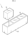
- FIG. 6 is a diagram for illustrating a battery pack according to an embodiment of the present disclosure.
- a battery pack 1 may include at least one battery module 10 according to the former embodiment and a pack case 50 for packaging the at least one battery module 10.
- the battery pack 1 may be provided to a vehicle as a fuel source of the vehicle.
- the battery pack 1 may be provided to an electric vehicle, a hybrid vehicle, and various other-type vehicles capable of using the battery pack 1 as a fuel source.
- the battery pack 1 may be provided in other devices, instruments or facilities such as an energy storage system using a secondary battery, in addition to the vehicle.
- the battery pack 1 of this embodiment and devices, instruments or facilities such as a vehicle, which have the battery pack 1 include the battery module 10 as described above, and thus it is possible to implement a battery pack 1 having all the advantages of the battery pack 10 described above, or devices, instruments, facilities or the like such as a vehicle, which have the battery pack 1.
Landscapes
- Engineering & Computer Science (AREA)
- Physics & Mathematics (AREA)
- Optics & Photonics (AREA)
- Mechanical Engineering (AREA)
- Plasma & Fusion (AREA)
- Chemical & Material Sciences (AREA)
- Chemical Kinetics & Catalysis (AREA)
- Electrochemistry (AREA)
- General Chemical & Material Sciences (AREA)
- Battery Mounting, Suspending (AREA)
- Connection Of Batteries Or Terminals (AREA)
Applications Claiming Priority (2)
| Application Number | Priority Date | Filing Date | Title |
|---|---|---|---|
| KR1020160060685A KR102101429B1 (ko) | 2016-05-18 | 2016-05-18 | 리드 용접 장치, 이러한 리드 용접 장치를 통해 제조되는 배터리 모듈 및 이러한 배터리 모듈을 포함하는 배터리 팩 |
| PCT/KR2017/000109 WO2017200177A1 (fr) | 2016-05-18 | 2017-01-04 | Appareil de soudage de fils, module de batterie fabriqué au moyen dudit appareil de soudage de fils et bloc-batterie comprenant ledit module de batterie |
Publications (3)
| Publication Number | Publication Date |
|---|---|
| EP3305460A1 true EP3305460A1 (fr) | 2018-04-11 |
| EP3305460A4 EP3305460A4 (fr) | 2018-07-11 |
| EP3305460B1 EP3305460B1 (fr) | 2023-12-06 |
Family
ID=60325960
Family Applications (1)
| Application Number | Title | Priority Date | Filing Date |
|---|---|---|---|
| EP17799535.4A Active EP3305460B1 (fr) | 2016-05-18 | 2017-01-04 | Module de batterie, procédé de soudage des fils d'electrode de cellules de batterie dans un module de batterie et bloc de batterie comprenant le module de batterie |
Country Status (9)
| Country | Link |
|---|---|
| US (1) | US10603747B2 (fr) |
| EP (1) | EP3305460B1 (fr) |
| JP (1) | JP6661765B2 (fr) |
| KR (1) | KR102101429B1 (fr) |
| CN (1) | CN107848071B (fr) |
| ES (1) | ES2968285T3 (fr) |
| HU (1) | HUE064632T2 (fr) |
| PL (1) | PL3305460T3 (fr) |
| WO (1) | WO2017200177A1 (fr) |
Cited By (3)
| Publication number | Priority date | Publication date | Assignee | Title |
|---|---|---|---|---|
| AT523340A1 (de) * | 2020-01-09 | 2021-07-15 | Voltlabor Gmbh | Spannvorrichtung |
| GB2604384A (en) * | 2021-03-04 | 2022-09-07 | Jaguar Land Rover Ltd | Clamping plates for battery manufacture |
| DE102023005238A1 (de) * | 2023-12-20 | 2025-06-26 | Mercedes-Benz Group AG | Schweißvorrichtung für Batteriezellen und Schweißverfahren |
Families Citing this family (18)
| Publication number | Priority date | Publication date | Assignee | Title |
|---|---|---|---|---|
| KR102155888B1 (ko) * | 2017-09-11 | 2020-09-14 | 주식회사 엘지화학 | 레이저 용접 지그 및 이를 포함하는 레이저 용접 장치 |
| KR102266473B1 (ko) | 2018-02-12 | 2021-06-16 | 주식회사 엘지에너지솔루션 | 스팟 용접용 지그 |
| KR102105665B1 (ko) | 2018-04-04 | 2020-05-29 | 주식회사 엘지화학 | 버스바를 가압하는 가압 지그 및 이를 포함하는 배터리 모듈 제조 시스템 |
| KR102258176B1 (ko) * | 2018-06-22 | 2021-07-16 | 주식회사 엘지에너지솔루션 | 전극 리드를 버스바에 밀착시키는 자동 가압 지그 장치 및 이를 포함하는 배터리 모듈 제조 시스템 |
| KR102315847B1 (ko) | 2018-10-05 | 2021-10-21 | 주식회사 엘지에너지솔루션 | 용접 불량을 방지할 수 있는 전지팩 프레임을 포함하는 전지팩 및 이를 제조하기 위한 가압 지그 |
| KR102774812B1 (ko) | 2019-01-08 | 2025-02-27 | 주식회사 엘지에너지솔루션 | 배터리 셀의 전극 리드 가접 지그 |
| KR102836078B1 (ko) * | 2019-10-18 | 2025-07-17 | 주식회사 엘지에너지솔루션 | 용접용 지그 |
| KR102506245B1 (ko) | 2019-11-14 | 2023-03-03 | 주식회사 엘지에너지솔루션 | 전지 모듈, 전지 모듈 제조 방법 및 전지 모듈을 포함하는 전지 팩 |
| CN112247437A (zh) * | 2020-01-20 | 2021-01-22 | 蜂巢能源科技有限公司 | 用于电芯的焊接的夹具以及焊接电芯的方法 |
| IT202000006016A1 (it) * | 2020-03-20 | 2021-09-20 | Comau Spa | "Apparecchiatura per assemblare celle di batteria o moduli di batteria" |
| KR102851616B1 (ko) * | 2020-07-15 | 2025-08-28 | 주식회사 엘지에너지솔루션 | 전극리드의 절곡 및 용접 장치 및 이를 이용한 전극리드의 용접 방법 |
| CN112271363B (zh) * | 2020-11-09 | 2023-05-09 | 深圳市日亚星科技有限公司 | 一种锂电池盖帽压焊用定位夹持机构 |
| KR102369375B1 (ko) * | 2020-11-10 | 2022-03-02 | 주식회사 모아 | 변위센서를 이용한 차량용 배터리 레이저 용접장치 |
| KR102332803B1 (ko) | 2020-11-10 | 2021-12-01 | 주식회사 모아 | 냉각장치가 구비된 차량용 배터리 레이저 용접장치 |
| WO2022177289A1 (fr) * | 2021-02-19 | 2022-08-25 | 주식회사 엘지에너지솔루션 | Dispositif de soudage à l'arc pour batterie secondaire et procédé de soudage utilisant ce dernier |
| JP7578083B2 (ja) * | 2021-09-09 | 2024-11-06 | トヨタ自動車株式会社 | 電池の製造方法 |
| WO2024205431A1 (fr) * | 2023-03-30 | 2024-10-03 | Aic Spółka Akcyjna | Système de soudage par faisceau laser de cellules galvaniques dans le processus de production d'un module de batterie |
| KR102807083B1 (ko) * | 2023-12-26 | 2025-05-15 | 주식회사 엘지에너지솔루션 | 레이저 용접 지그, 레이저 용접 시스템 및 이를 이용하는 용접 방법 |
Family Cites Families (19)
| Publication number | Priority date | Publication date | Assignee | Title |
|---|---|---|---|---|
| JP2001102610A (ja) * | 1999-09-29 | 2001-04-13 | Kanegafuchi Chem Ind Co Ltd | 半田バンプ付きリード線、太陽電池用リード線取付け装置及び太陽電池の製造方法 |
| ATE487238T1 (de) * | 1999-09-29 | 2010-11-15 | Kaneka Corp | Verfahren und gerät zur automatischen lötung von einem anschlussdraht an einer sonnenzellenbatterie |
| WO2006109610A1 (fr) * | 2005-04-05 | 2006-10-19 | Nec Corporation | Procede de production pour un assemblage de dispositif electrique et assemblage de dispositif electrique |
| JP4728758B2 (ja) | 2005-05-10 | 2011-07-20 | 日本電気株式会社 | 電気デバイスモジュールの製造方法及び電気デバイスモジュール |
| KR100936262B1 (ko) * | 2005-10-21 | 2010-01-12 | 주식회사 엘지화학 | 신규한 구조의 전기 접속용 버스 바 및 그것을 포함하고있는 전지모듈 |
| US8557411B2 (en) * | 2009-08-14 | 2013-10-15 | Samsung Sdi Co., Ltd. | Secondary battery with a connection tab folded around an insulator and method of manufacturing the same |
| WO2012148100A2 (fr) * | 2011-04-26 | 2012-11-01 | 주식회사 엘지화학 | Nouvelle structure de barre omnibus, et module de batterie la comprenant |
| WO2012173451A2 (fr) * | 2011-06-17 | 2012-12-20 | 주식회사 엘지화학 | Connecteur de soudage et module de batterie et bloc-batterie comprenant ledit connecteur |
| KR20120065279A (ko) * | 2012-01-04 | 2012-06-20 | 아이피지 포토닉스 코리아(주) | 배터리 전극 용접 장치 및 방법 |
| KR20130131658A (ko) * | 2012-05-24 | 2013-12-04 | 에스케이이노베이션 주식회사 | 이차 전지용 레이저 용접 지그 및 그 용접 방법 |
| KR101941686B1 (ko) * | 2012-06-20 | 2019-01-24 | 에스케이이노베이션 주식회사 | 전극 탭 용접 방법 |
| JP6020900B2 (ja) * | 2012-10-10 | 2016-11-02 | 株式会社オートネットワーク技術研究所 | 蓄電モジュール |
| EP3050162B1 (fr) | 2013-09-25 | 2018-10-24 | TE Connectivity Corporation | Système électrique |
| KR101821378B1 (ko) | 2014-03-31 | 2018-01-23 | 주식회사 엘지화학 | 전극 리드와 버스바 사이의 결합력 및 공정성이 향상된 배터리 모듈 및 이를 포함하는 배터리 팩 |
| WO2015178153A1 (fr) * | 2014-05-21 | 2015-11-26 | 旭化成Fdkエナジーデバイス株式会社 | Module d'accumulation d'électricité et procédé de fabrication de module d'accumulation d'électricité |
| JP6357944B2 (ja) * | 2014-07-23 | 2018-07-18 | 日産自動車株式会社 | 組電池 |
| KR101773104B1 (ko) * | 2014-07-31 | 2017-08-30 | 주식회사 엘지화학 | 배터리 모듈 |
| WO2017068707A1 (fr) * | 2015-10-22 | 2017-04-27 | 日産自動車株式会社 | Procédé et dispositif de fabrication de batterie assemblée |
| KR102090787B1 (ko) * | 2017-01-11 | 2020-03-18 | 주식회사 엘지화학 | 레이저 용접용 지그 어셈블리 |
-
2016
- 2016-05-18 KR KR1020160060685A patent/KR102101429B1/ko active Active
-
2017
- 2017-01-04 US US15/737,547 patent/US10603747B2/en active Active
- 2017-01-04 PL PL17799535.4T patent/PL3305460T3/pl unknown
- 2017-01-04 JP JP2018524204A patent/JP6661765B2/ja active Active
- 2017-01-04 WO PCT/KR2017/000109 patent/WO2017200177A1/fr not_active Ceased
- 2017-01-04 HU HUE17799535A patent/HUE064632T2/hu unknown
- 2017-01-04 ES ES17799535T patent/ES2968285T3/es active Active
- 2017-01-04 CN CN201780002336.3A patent/CN107848071B/zh active Active
- 2017-01-04 EP EP17799535.4A patent/EP3305460B1/fr active Active
Cited By (6)
| Publication number | Priority date | Publication date | Assignee | Title |
|---|---|---|---|---|
| AT523340A1 (de) * | 2020-01-09 | 2021-07-15 | Voltlabor Gmbh | Spannvorrichtung |
| AT523340B1 (de) * | 2020-01-09 | 2022-12-15 | Miba Battery Systems Gmbh | Spannvorrichtung |
| GB2604384A (en) * | 2021-03-04 | 2022-09-07 | Jaguar Land Rover Ltd | Clamping plates for battery manufacture |
| WO2022184865A1 (fr) * | 2021-03-04 | 2022-09-09 | Jaguar Land Rover Limited | Plaques de serrage pour fabrication de batteries |
| GB2604384B (en) * | 2021-03-04 | 2024-12-25 | Jaguar Land Rover Ltd | Clamping plates for battery manufacture |
| DE102023005238A1 (de) * | 2023-12-20 | 2025-06-26 | Mercedes-Benz Group AG | Schweißvorrichtung für Batteriezellen und Schweißverfahren |
Also Published As
| Publication number | Publication date |
|---|---|
| KR102101429B1 (ko) | 2020-04-16 |
| JP2018533820A (ja) | 2018-11-15 |
| PL3305460T3 (pl) | 2024-03-04 |
| WO2017200177A1 (fr) | 2017-11-23 |
| US20180169790A1 (en) | 2018-06-21 |
| HUE064632T2 (hu) | 2024-04-28 |
| EP3305460A4 (fr) | 2018-07-11 |
| ES2968285T3 (es) | 2024-05-08 |
| CN107848071B (zh) | 2020-02-28 |
| US10603747B2 (en) | 2020-03-31 |
| KR20170130091A (ko) | 2017-11-28 |
| JP6661765B2 (ja) | 2020-03-11 |
| CN107848071A (zh) | 2018-03-27 |
| EP3305460B1 (fr) | 2023-12-06 |
Similar Documents
| Publication | Publication Date | Title |
|---|---|---|
| US10603747B2 (en) | Lead welding apparatus, battery module manufactured by the lead welding apparatus, and battery pack comprising the battery module | |
| US12244029B2 (en) | Battery module and battery pack comprising battery module | |
| EP3561902B1 (fr) | Module de batterie, bloc-batterie comprenant le module de batterie et véhicule comprenant le bloc-batterie | |
| EP3675239B1 (fr) | Module de batterie et bloc-batterie et automobile le comprenant | |
| EP3336928B1 (fr) | Module de batterie, bloc-batterie comprenant un module de batterie, et véhicule comprenant un bloc-batterie | |
| US11456502B2 (en) | Battery module, battery pack comprising same battery module, and vehicle comprising same battery pack | |
| EP3675223A1 (fr) | Module de batterie, bloc-batterie comprenant le module de batterie, et automobile comprenant le bloc-batterie | |
| EP3892417B1 (fr) | Gabarit de soudage d'agrafage du conducteur d'electrode d'une cellule de batterie | |
| EP3291360A1 (fr) | Bloc-batterie et véhicule incluant un tel bloc-batterie | |
| EP3799155B1 (fr) | Module de batterie, bloc-batterie comprenant le module de batterie et véhicule comprenant le bloc-batterie | |
| EP3567669A1 (fr) | Module de batteries, bloc-batterie comprenant le module de batteries, et automobile comprenant le bloc-batterie | |
| EP4030547A1 (fr) | Module de batterie, bloc-batterie le comprenant, et véhicule | |
| EP3373359A1 (fr) | Module de batterie, bloc de batteries comprenant un tel module de batterie et véhicule comprenant un tel bloc de batteries | |
| US20220393306A1 (en) | Battery Module, Manufacturing Method for Battery Module, and Vehicle and Battery Pack Comprising Battery Module |
Legal Events
| Date | Code | Title | Description |
|---|---|---|---|
| STAA | Information on the status of an ep patent application or granted ep patent |
Free format text: STATUS: THE INTERNATIONAL PUBLICATION HAS BEEN MADE |
|
| PUAI | Public reference made under article 153(3) epc to a published international application that has entered the european phase |
Free format text: ORIGINAL CODE: 0009012 |
|
| STAA | Information on the status of an ep patent application or granted ep patent |
Free format text: STATUS: REQUEST FOR EXAMINATION WAS MADE |
|
| 17P | Request for examination filed |
Effective date: 20180104 |
|
| AK | Designated contracting states |
Kind code of ref document: A1 Designated state(s): AL AT BE BG CH CY CZ DE DK EE ES FI FR GB GR HR HU IE IS IT LI LT LU LV MC MK MT NL NO PL PT RO RS SE SI SK SM TR |
|
| AX | Request for extension of the european patent |
Extension state: BA ME |
|
| A4 | Supplementary search report drawn up and despatched |
Effective date: 20180608 |
|
| RIC1 | Information provided on ipc code assigned before grant |
Ipc: B23K 37/04 20060101ALI20180604BHEP Ipc: B23K 26/21 20140101AFI20180604BHEP Ipc: B23K 26/70 20140101ALI20180604BHEP Ipc: H01M 2/10 20060101ALI20180604BHEP Ipc: B23K 101/36 20060101ALI20180604BHEP Ipc: B23K 31/02 20060101ALI20180604BHEP Ipc: B23K 26/244 20140101ALI20180604BHEP |
|
| DAV | Request for validation of the european patent (deleted) | ||
| DAX | Request for extension of the european patent (deleted) | ||
| STAA | Information on the status of an ep patent application or granted ep patent |
Free format text: STATUS: EXAMINATION IS IN PROGRESS |
|
| 17Q | First examination report despatched |
Effective date: 20210707 |
|
| RAP1 | Party data changed (applicant data changed or rights of an application transferred) |
Owner name: LG ENERGY SOLUTION LTD. |
|
| RAP3 | Party data changed (applicant data changed or rights of an application transferred) |
Owner name: LG ENERGY SOLUTION, LTD. |
|
| REG | Reference to a national code |
Ref country code: DE Ref legal event code: R079 Free format text: PREVIOUS MAIN CLASS: B23K0026210000 Ipc: H01M0050211000 Ref document number: 602017077273 Country of ref document: DE |
|
| RIC1 | Information provided on ipc code assigned before grant |
Ipc: B23K 26/70 20140101ALI20230426BHEP Ipc: B23K 26/244 20140101ALI20230426BHEP Ipc: B23K 31/02 20060101ALI20230426BHEP Ipc: B23K 37/04 20060101ALI20230426BHEP Ipc: B23K 26/21 20140101ALI20230426BHEP Ipc: H01M 50/211 20210101AFI20230426BHEP |
|
| GRAP | Despatch of communication of intention to grant a patent |
Free format text: ORIGINAL CODE: EPIDOSNIGR1 |
|
| STAA | Information on the status of an ep patent application or granted ep patent |
Free format text: STATUS: GRANT OF PATENT IS INTENDED |
|
| INTG | Intention to grant announced |
Effective date: 20230704 |
|
| P01 | Opt-out of the competence of the unified patent court (upc) registered |
Effective date: 20230801 |
|
| GRAS | Grant fee paid |
Free format text: ORIGINAL CODE: EPIDOSNIGR3 |
|
| GRAA | (expected) grant |
Free format text: ORIGINAL CODE: 0009210 |
|
| STAA | Information on the status of an ep patent application or granted ep patent |
Free format text: STATUS: THE PATENT HAS BEEN GRANTED |
|
| AK | Designated contracting states |
Kind code of ref document: B1 Designated state(s): AL AT BE BG CH CY CZ DE DK EE ES FI FR GB GR HR HU IE IS IT LI LT LU LV MC MK MT NL NO PL PT RO RS SE SI SK SM TR |
|
| REG | Reference to a national code |
Ref country code: GB Ref legal event code: FG4D |
|
| REG | Reference to a national code |
Ref country code: CH Ref legal event code: EP |
|
| REG | Reference to a national code |
Ref country code: DE Ref legal event code: R096 Ref document number: 602017077273 Country of ref document: DE |
|
| REG | Reference to a national code |
Ref country code: IE Ref legal event code: FG4D |
|
| REG | Reference to a national code |
Ref country code: NL Ref legal event code: FP |
|
| REG | Reference to a national code |
Ref country code: SE Ref legal event code: TRGR |
|
| REG | Reference to a national code |
Ref country code: LT Ref legal event code: MG9D |
|
| PG25 | Lapsed in a contracting state [announced via postgrant information from national office to epo] |
Ref country code: GR Free format text: LAPSE BECAUSE OF FAILURE TO SUBMIT A TRANSLATION OF THE DESCRIPTION OR TO PAY THE FEE WITHIN THE PRESCRIBED TIME-LIMIT Effective date: 20240307 |
|
| PG25 | Lapsed in a contracting state [announced via postgrant information from national office to epo] |
Ref country code: LT Free format text: LAPSE BECAUSE OF FAILURE TO SUBMIT A TRANSLATION OF THE DESCRIPTION OR TO PAY THE FEE WITHIN THE PRESCRIBED TIME-LIMIT Effective date: 20231206 |
|
| REG | Reference to a national code |
Ref country code: HU Ref legal event code: AG4A Ref document number: E064632 Country of ref document: HU |
|
| PG25 | Lapsed in a contracting state [announced via postgrant information from national office to epo] |
Ref country code: LT Free format text: LAPSE BECAUSE OF FAILURE TO SUBMIT A TRANSLATION OF THE DESCRIPTION OR TO PAY THE FEE WITHIN THE PRESCRIBED TIME-LIMIT Effective date: 20231206 Ref country code: GR Free format text: LAPSE BECAUSE OF FAILURE TO SUBMIT A TRANSLATION OF THE DESCRIPTION OR TO PAY THE FEE WITHIN THE PRESCRIBED TIME-LIMIT Effective date: 20240307 Ref country code: BG Free format text: LAPSE BECAUSE OF FAILURE TO SUBMIT A TRANSLATION OF THE DESCRIPTION OR TO PAY THE FEE WITHIN THE PRESCRIBED TIME-LIMIT Effective date: 20240306 |
|
| REG | Reference to a national code |
Ref country code: ES Ref legal event code: FG2A Ref document number: 2968285 Country of ref document: ES Kind code of ref document: T3 Effective date: 20240508 |
|
| REG | Reference to a national code |
Ref country code: AT Ref legal event code: MK05 Ref document number: 1639286 Country of ref document: AT Kind code of ref document: T Effective date: 20231206 |
|
| PG25 | Lapsed in a contracting state [announced via postgrant information from national office to epo] |
Ref country code: RS Free format text: LAPSE BECAUSE OF FAILURE TO SUBMIT A TRANSLATION OF THE DESCRIPTION OR TO PAY THE FEE WITHIN THE PRESCRIBED TIME-LIMIT Effective date: 20231206 Ref country code: NO Free format text: LAPSE BECAUSE OF FAILURE TO SUBMIT A TRANSLATION OF THE DESCRIPTION OR TO PAY THE FEE WITHIN THE PRESCRIBED TIME-LIMIT Effective date: 20240306 Ref country code: LV Free format text: LAPSE BECAUSE OF FAILURE TO SUBMIT A TRANSLATION OF THE DESCRIPTION OR TO PAY THE FEE WITHIN THE PRESCRIBED TIME-LIMIT Effective date: 20231206 Ref country code: HR Free format text: LAPSE BECAUSE OF FAILURE TO SUBMIT A TRANSLATION OF THE DESCRIPTION OR TO PAY THE FEE WITHIN THE PRESCRIBED TIME-LIMIT Effective date: 20231206 |
|
| PG25 | Lapsed in a contracting state [announced via postgrant information from national office to epo] |
Ref country code: IS Free format text: LAPSE BECAUSE OF FAILURE TO SUBMIT A TRANSLATION OF THE DESCRIPTION OR TO PAY THE FEE WITHIN THE PRESCRIBED TIME-LIMIT Effective date: 20240406 |
|
| PG25 | Lapsed in a contracting state [announced via postgrant information from national office to epo] |
Ref country code: CZ Free format text: LAPSE BECAUSE OF FAILURE TO SUBMIT A TRANSLATION OF THE DESCRIPTION OR TO PAY THE FEE WITHIN THE PRESCRIBED TIME-LIMIT Effective date: 20231206 Ref country code: AT Free format text: LAPSE BECAUSE OF FAILURE TO SUBMIT A TRANSLATION OF THE DESCRIPTION OR TO PAY THE FEE WITHIN THE PRESCRIBED TIME-LIMIT Effective date: 20231206 |
|
| PG25 | Lapsed in a contracting state [announced via postgrant information from national office to epo] |
Ref country code: SK Free format text: LAPSE BECAUSE OF FAILURE TO SUBMIT A TRANSLATION OF THE DESCRIPTION OR TO PAY THE FEE WITHIN THE PRESCRIBED TIME-LIMIT Effective date: 20231206 |
|
| PG25 | Lapsed in a contracting state [announced via postgrant information from national office to epo] |
Ref country code: SM Free format text: LAPSE BECAUSE OF FAILURE TO SUBMIT A TRANSLATION OF THE DESCRIPTION OR TO PAY THE FEE WITHIN THE PRESCRIBED TIME-LIMIT Effective date: 20231206 Ref country code: SK Free format text: LAPSE BECAUSE OF FAILURE TO SUBMIT A TRANSLATION OF THE DESCRIPTION OR TO PAY THE FEE WITHIN THE PRESCRIBED TIME-LIMIT Effective date: 20231206 Ref country code: RO Free format text: LAPSE BECAUSE OF FAILURE TO SUBMIT A TRANSLATION OF THE DESCRIPTION OR TO PAY THE FEE WITHIN THE PRESCRIBED TIME-LIMIT Effective date: 20231206 Ref country code: IS Free format text: LAPSE BECAUSE OF FAILURE TO SUBMIT A TRANSLATION OF THE DESCRIPTION OR TO PAY THE FEE WITHIN THE PRESCRIBED TIME-LIMIT Effective date: 20240406 Ref country code: EE Free format text: LAPSE BECAUSE OF FAILURE TO SUBMIT A TRANSLATION OF THE DESCRIPTION OR TO PAY THE FEE WITHIN THE PRESCRIBED TIME-LIMIT Effective date: 20231206 Ref country code: CZ Free format text: LAPSE BECAUSE OF FAILURE TO SUBMIT A TRANSLATION OF THE DESCRIPTION OR TO PAY THE FEE WITHIN THE PRESCRIBED TIME-LIMIT Effective date: 20231206 Ref country code: AT Free format text: LAPSE BECAUSE OF FAILURE TO SUBMIT A TRANSLATION OF THE DESCRIPTION OR TO PAY THE FEE WITHIN THE PRESCRIBED TIME-LIMIT Effective date: 20231206 |
|
| PG25 | Lapsed in a contracting state [announced via postgrant information from national office to epo] |
Ref country code: PT Free format text: LAPSE BECAUSE OF FAILURE TO SUBMIT A TRANSLATION OF THE DESCRIPTION OR TO PAY THE FEE WITHIN THE PRESCRIBED TIME-LIMIT Effective date: 20240408 |
|
| PG25 | Lapsed in a contracting state [announced via postgrant information from national office to epo] |
Ref country code: PT Free format text: LAPSE BECAUSE OF FAILURE TO SUBMIT A TRANSLATION OF THE DESCRIPTION OR TO PAY THE FEE WITHIN THE PRESCRIBED TIME-LIMIT Effective date: 20240408 |
|
| REG | Reference to a national code |
Ref country code: CH Ref legal event code: PL |
|
| REG | Reference to a national code |
Ref country code: DE Ref legal event code: R097 Ref document number: 602017077273 Country of ref document: DE |
|
| PG25 | Lapsed in a contracting state [announced via postgrant information from national office to epo] |
Ref country code: LU Free format text: LAPSE BECAUSE OF NON-PAYMENT OF DUE FEES Effective date: 20240104 |
|
| PG25 | Lapsed in a contracting state [announced via postgrant information from national office to epo] |
Ref country code: LU Free format text: LAPSE BECAUSE OF NON-PAYMENT OF DUE FEES Effective date: 20240104 Ref country code: MC Free format text: LAPSE BECAUSE OF FAILURE TO SUBMIT A TRANSLATION OF THE DESCRIPTION OR TO PAY THE FEE WITHIN THE PRESCRIBED TIME-LIMIT Effective date: 20231206 |
|
| PG25 | Lapsed in a contracting state [announced via postgrant information from national office to epo] |
Ref country code: DK Free format text: LAPSE BECAUSE OF FAILURE TO SUBMIT A TRANSLATION OF THE DESCRIPTION OR TO PAY THE FEE WITHIN THE PRESCRIBED TIME-LIMIT Effective date: 20231206 |
|
| PLBE | No opposition filed within time limit |
Free format text: ORIGINAL CODE: 0009261 |
|
| STAA | Information on the status of an ep patent application or granted ep patent |
Free format text: STATUS: NO OPPOSITION FILED WITHIN TIME LIMIT |
|
| PG25 | Lapsed in a contracting state [announced via postgrant information from national office to epo] |
Ref country code: BE Free format text: LAPSE BECAUSE OF NON-PAYMENT OF DUE FEES Effective date: 20240131 |
|
| PG25 | Lapsed in a contracting state [announced via postgrant information from national office to epo] |
Ref country code: CH Free format text: LAPSE BECAUSE OF NON-PAYMENT OF DUE FEES Effective date: 20240131 |
|
| PG25 | Lapsed in a contracting state [announced via postgrant information from national office to epo] |
Ref country code: SI Free format text: LAPSE BECAUSE OF FAILURE TO SUBMIT A TRANSLATION OF THE DESCRIPTION OR TO PAY THE FEE WITHIN THE PRESCRIBED TIME-LIMIT Effective date: 20231206 |
|
| PG25 | Lapsed in a contracting state [announced via postgrant information from national office to epo] |
Ref country code: SI Free format text: LAPSE BECAUSE OF FAILURE TO SUBMIT A TRANSLATION OF THE DESCRIPTION OR TO PAY THE FEE WITHIN THE PRESCRIBED TIME-LIMIT Effective date: 20231206 Ref country code: DK Free format text: LAPSE BECAUSE OF FAILURE TO SUBMIT A TRANSLATION OF THE DESCRIPTION OR TO PAY THE FEE WITHIN THE PRESCRIBED TIME-LIMIT Effective date: 20231206 Ref country code: CH Free format text: LAPSE BECAUSE OF NON-PAYMENT OF DUE FEES Effective date: 20240131 Ref country code: BE Free format text: LAPSE BECAUSE OF NON-PAYMENT OF DUE FEES Effective date: 20240131 |
|
| REG | Reference to a national code |
Ref country code: BE Ref legal event code: MM Effective date: 20240131 |
|
| 26N | No opposition filed |
Effective date: 20240909 |
|
| PG25 | Lapsed in a contracting state [announced via postgrant information from national office to epo] |
Ref country code: IE Free format text: LAPSE BECAUSE OF NON-PAYMENT OF DUE FEES Effective date: 20240104 |
|
| PG25 | Lapsed in a contracting state [announced via postgrant information from national office to epo] |
Ref country code: IE Free format text: LAPSE BECAUSE OF NON-PAYMENT OF DUE FEES Effective date: 20240104 |
|
| PG25 | Lapsed in a contracting state [announced via postgrant information from national office to epo] |
Ref country code: CY Free format text: LAPSE BECAUSE OF FAILURE TO SUBMIT A TRANSLATION OF THE DESCRIPTION OR TO PAY THE FEE WITHIN THE PRESCRIBED TIME-LIMIT; INVALID AB INITIO Effective date: 20170104 |
|
| PG25 | Lapsed in a contracting state [announced via postgrant information from national office to epo] |
Ref country code: FI Free format text: LAPSE BECAUSE OF FAILURE TO SUBMIT A TRANSLATION OF THE DESCRIPTION OR TO PAY THE FEE WITHIN THE PRESCRIBED TIME-LIMIT Effective date: 20231207 |
|
| PGFP | Annual fee paid to national office [announced via postgrant information from national office to epo] |
Ref country code: GB Payment date: 20251222 Year of fee payment: 10 |
|
| PGFP | Annual fee paid to national office [announced via postgrant information from national office to epo] |
Ref country code: NL Payment date: 20251223 Year of fee payment: 10 Ref country code: FR Payment date: 20251223 Year of fee payment: 10 |
|
| PGFP | Annual fee paid to national office [announced via postgrant information from national office to epo] |
Ref country code: SE Payment date: 20251223 Year of fee payment: 10 |
|
| PGFP | Annual fee paid to national office [announced via postgrant information from national office to epo] |
Ref country code: PL Payment date: 20251223 Year of fee payment: 10 |
|
| PGFP | Annual fee paid to national office [announced via postgrant information from national office to epo] |
Ref country code: HU Payment date: 20260129 Year of fee payment: 10 |
|
| PGFP | Annual fee paid to national office [announced via postgrant information from national office to epo] |
Ref country code: ES Payment date: 20260212 Year of fee payment: 10 |
|
| PGFP | Annual fee paid to national office [announced via postgrant information from national office to epo] |
Ref country code: DE Payment date: 20251222 Year of fee payment: 10 |
|
| PGFP | Annual fee paid to national office [announced via postgrant information from national office to epo] |
Ref country code: IT Payment date: 20251223 Year of fee payment: 10 |
|
| PGFP | Annual fee paid to national office [announced via postgrant information from national office to epo] |
Ref country code: TR Payment date: 20260102 Year of fee payment: 10 |