EP3305471A1 - Dispositif de commutation pour une machine-outil portable, en particulier un marteau perforateur et/ou un marteau burineur - Google Patents
Dispositif de commutation pour une machine-outil portable, en particulier un marteau perforateur et/ou un marteau burineur Download PDFInfo
- Publication number
- EP3305471A1 EP3305471A1 EP17190063.2A EP17190063A EP3305471A1 EP 3305471 A1 EP3305471 A1 EP 3305471A1 EP 17190063 A EP17190063 A EP 17190063A EP 3305471 A1 EP3305471 A1 EP 3305471A1
- Authority
- EP
- European Patent Office
- Prior art keywords
- locking
- power tool
- portable power
- switching device
- operating
- Prior art date
- Legal status (The legal status is an assumption and is not a legal conclusion. Google has not performed a legal analysis and makes no representation as to the accuracy of the status listed.)
- Granted
Links
Images



Classifications
-
- B—PERFORMING OPERATIONS; TRANSPORTING
- B25—HAND TOOLS; PORTABLE POWER-DRIVEN TOOLS; MANIPULATORS
- B25D—PERCUSSIVE TOOLS
- B25D16/00—Portable percussive machines with superimposed rotation, the rotational movement of the output shaft of a motor being modified to generate axial impacts on the tool bit
- B25D16/006—Mode changers; Mechanisms connected thereto
-
- B—PERFORMING OPERATIONS; TRANSPORTING
- B25—HAND TOOLS; PORTABLE POWER-DRIVEN TOOLS; MANIPULATORS
- B25D—PERCUSSIVE TOOLS
- B25D17/00—Details of, or accessories for, portable power-driven percussive tools
- B25D17/04—Handles; Handle mountings
- B25D17/043—Handles resiliently mounted relative to the hammer housing
-
- B—PERFORMING OPERATIONS; TRANSPORTING
- B25—HAND TOOLS; PORTABLE POWER-DRIVEN TOOLS; MANIPULATORS
- B25D—PERCUSSIVE TOOLS
- B25D2216/00—Details of portable percussive machines with superimposed rotation, the rotational movement of the output shaft of a motor being modified to generate axial impacts on the tool bit
- B25D2216/0007—Details of percussion or rotation modes
- B25D2216/0023—Tools having a percussion-and-rotation mode
-
- B—PERFORMING OPERATIONS; TRANSPORTING
- B25—HAND TOOLS; PORTABLE POWER-DRIVEN TOOLS; MANIPULATORS
- B25D—PERCUSSIVE TOOLS
- B25D2216/00—Details of portable percussive machines with superimposed rotation, the rotational movement of the output shaft of a motor being modified to generate axial impacts on the tool bit
- B25D2216/0084—Mode-changing mechanisms
-
- B—PERFORMING OPERATIONS; TRANSPORTING
- B25—HAND TOOLS; PORTABLE POWER-DRIVEN TOOLS; MANIPULATORS
- B25D—PERCUSSIVE TOOLS
- B25D2250/00—General details of portable percussive tools; Components used in portable percussive tools
- B25D2250/121—Housing details
-
- B—PERFORMING OPERATIONS; TRANSPORTING
- B25—HAND TOOLS; PORTABLE POWER-DRIVEN TOOLS; MANIPULATORS
- B25D—PERCUSSIVE TOOLS
- B25D2250/00—General details of portable percussive tools; Components used in portable percussive tools
- B25D2250/221—Sensors
-
- B—PERFORMING OPERATIONS; TRANSPORTING
- B25—HAND TOOLS; PORTABLE POWER-DRIVEN TOOLS; MANIPULATORS
- B25D—PERCUSSIVE TOOLS
- B25D2250/00—General details of portable percussive tools; Components used in portable percussive tools
- B25D2250/255—Switches
-
- B—PERFORMING OPERATIONS; TRANSPORTING
- B25—HAND TOOLS; PORTABLE POWER-DRIVEN TOOLS; MANIPULATORS
- B25D—PERCUSSIVE TOOLS
- B25D2250/00—General details of portable percussive tools; Components used in portable percussive tools
- B25D2250/255—Switches
- B25D2250/261—Means for locking an operative switch on
Definitions
- Switching devices for portable machine tools in particular for rotary and / or chisel hammers, are already known, the known switching devices comprising at least one mode selection unit having at least one movable, in particular rotatable, mounted control element for selecting a mode of operation of the portable machine tools, and at least one locking unit to a locking of the operating element in at least one movement position of the operating element, in particular in at least one rotational position of the operating element comprise.
- the invention relates to a switching device for a portable power tool, in particular for a drill and / or chisel, with at least one operating mode selection unit having at least one movable, in particular rotatable, mounted control element for selecting a mode of operation of the portable power tool, and at least a locking unit to a locking of the operating element in at least one movement position of the operating element, in particular in at least one, in particular an operating mode associated, rotational position of the operating element.
- the locking unit has at least one movably mounted locking element which, depending on a locking position of the Arresting element triggers an electrical and / or electronic signal to a circuit of a mode of operation of the portable power tool.
- a “locking unit” is to be understood in particular a unit which has at least two mutually cooperating elements, in particular locking elements, which are intended to cooperate with one another to lock, in particular brought into contact, so that transmit a locking force on the two elements can be to secure / hold another element in at least one movement position of the other element, in particular to avoid unwanted movement of the other element.
- "intended” is intended to be understood in particular specifically designed and / or specially equipped. The fact that an object is intended for a specific function should in particular mean that the object fulfills and / or executes this specific function in at least one application and / or operating state.
- the operating element is preferably rotatably mounted about a movement axis of the operating element.
- the movement axis of the operating element preferably runs transversely, in particular at least substantially perpendicular, to a main axis of extension of the portable power tool and / or to a striking axis of a percussion unit of the portable power tool.
- substantially perpendicular is intended here to define, in particular, an orientation of a direction relative to a reference direction, the direction and the reference direction, in particular in one plane, including an angle of 90 ° and the angle a maximum deviation of, in particular, less than 8 °, advantageously less than 5 ° and particularly advantageously less than 2 °.
- the locking unit is preferably provided to lock the operating element in a movement position of the operating element, in particular in at least one, in particular a mode assigned, rotational position of the operating element.
- the locking unit is designed as a latching unit.
- the locking unit comprises the locking element, which is designed as a latching element.
- the locking element is intended to cooperate with a latching recess of a locking contour of the locking unit to lock the control element in a movement position of the operating element, in particular in at least one, in particular a mode associated, rotational position of the operating element.
- the locking element movably mounted on the operating element, in particular translationally movable.
- a movement axis of the locking element preferably extends transversely, in particular at least substantially perpendicular, to the movement axis of the operating element.
- the locking unit comprises a spring element, which acts on the locking element with a spring force in the direction of a locking position, in particular in a direction away from the control direction.
- the locking element is preferably provided to cooperate with a switching element of the switching device to trigger an electrical and / or electronic signal to a circuit of a mode of the portable power tool, in particular in a chisel operation of the portable power tool associated locking position of the locking element.
- a "locking position of the locking element” is to be understood in particular a position of the locking element, in which the locking element locks the operating element in a movement position of the operating element and engages in particular in the locking contour of the locking unit, in particular engages in the locking recess of the locking contour.
- the locking element may cooperate directly with the switching element in the locking position of the locking element or cooperate with the switching element with the interposition of a further element, in particular an intermediate element, the switching device.
- the mode selector unit is provided in particular at least for a selection of a mode of operation of the portable power tool designed as a drilling operation, as a hammer drill operation and / or as a chisel operation.
- a drilling operation an insertion tool is preferably rotatably drivable in a manner already known to a person skilled in the art.
- a rotary hammer operation preferably an insert tool can be driven in a rotating and hammering manner in a manner already known to a person skilled in the art.
- an insert tool can preferably be driven to strike in a manner already known to a person skilled in the art.
- a drill and / or chisel hammer in particular counts to a device class with high drive power.
- the portable power tool preferably has a, already known to a person skilled in the unit for determining a relative angle of rotation of a housing of the portable power tool. Examples of units for determining a relative angle of rotation are, for example, in the documents WO 88 06 508 A3 . DE 43 44 817 C2 respectively.
- EP 0 666 148 A2 such as DE 196 41 618 A1 described.
- a risk of unintentionally occurring rotational accidents in particular those as already mentioned above, rotational accidents, low because the insert tool can only be driven by striking.
- individual electrical system functions of the portable power tool are preferably to be set differently than in drilling operation and / or in hammer drill operation.
- unwanted shutdown or reduction of drive power of the portable power tool in a chisel operation due to exceeding a threshold value of a rotation angle is undesirable because it can slow down a work process.
- At least the unit for determining a relative angle of rotation of a housing of the portable power tool should be deactivated and / or individual operating parameters of the portable power tool should be changed.
- a reliable detection of a mode is advantageous to allow reliable deactivation and / or change of operating parameters.
- a reliable and reliable assignment of a movement position of the operating element to an operating mode of the portable power tool can advantageously be made possible in order to preferably realize a reliable switching of an operating mode.
- a reliable triggering of an electrical and / or electronic signal to a circuit of an operating mode of the portable power tool can be realized.
- the mode selector unit at least one, in particular translationally, movably mounted intermediate element which is movable to a triggering of an electrical and / or electronic signal to a circuit of an operating mode of the portable power tool in response to a movement of the locking element in at least one locking position of the locking element by the locking element.
- the intermediate element is movable to a triggering of an electrical and / or electronic signal to a circuit of an operating mode of the portable power tool in response to a movement of the locking element in at least one of a chisel operation of the portable power tool associated locking position of the locking element by the locking element.
- the intermediate element is intended to cooperate directly with the switching element of the switching device, in particular with a locking element facing away from the end of the intermediate element.
- the switching element is preferably designed as a Hall sensor.
- On the intermediate element is preferably a magnetic element, in particular a permanent magnet, arranged, which is intended to cooperate to trigger a electrical and / or electronic signal with the Hall sensor in a manner already known to a person skilled in the art.
- the switching element is designed as an electrical switch, in particular as a microswitch, as an inductive proximity sensor, as a light barrier or as another switching element which appears expedient to a person skilled in the art.
- a bridging of a distance between the locking element and the switching element can be made structurally simple. It can be advantageously made possible an arrangement of the switching element at a distance from the locking element, in particular for enabling a compact arrangement of electrical and / or electronic components in an assembly, which is arranged spaced from the locking element in a housing of the portable power tool. It can advantageously be a safety distance, such as an air gap distance, a creeping o. The like., Constructively simple compliance.
- a reliable and reliable assignment of a movement position of the operating element to an operating mode of the portable power tool can be made possible in order to preferably realize a reliable switching of an operating mode.
- a reliable triggering of an electrical and / or electronic signal to a circuit of an operating mode of the portable power tool can be realized.
- the locking unit has at least one latching contour, which cooperates with the locking element to lock the operating element in at least one movement position, in particular in at least one movement position associated movement position, wherein at least the intermediate element in at least one state at least partially in engages the locking contour.
- the intermediate element engages at least partially in a chisel operation associated with a recess of the locking contour.
- the locking member engages in a chisel operation associated movement position of the operating element and in the bit position associated with the locking position of the locking element at least partially in the recess of the locking contour, in particular to lock the control element in a chisel operation associated movement position of the control element.
- the locking element preferably at least partially moves the intermediate element out of the latching recess assigned to a bit operation.
- the locking contour is formed integrally with a housing, in particular with a gear housing, the portable power tool.
- the catch contour is viewed along the axis of movement of the operating element under the control.
- the operating element preferably covers the catch contour in a state of the operating element arranged on the housing, in particular on the gear housing, of the portable machine tool, in particular along a direction extending at least substantially parallel to the movement axis of the operating element.
- substantially parallel is to be understood here as meaning, in particular, an alignment of a direction relative to a reference direction, in particular in a plane, wherein the direction relative to the reference direction is a deviation, in particular less than 8 °, advantageously less than 5 ° and particularly advantageously less than 2 °.
- a reliable and reliable assignment of a movement position of the operating element to an operating mode of the portable machine tool can be made possible, preferably to realize a reliable circuit of an operating mode.
- a reliable triggering of an electrical and / or electronic signal to a circuit of an operating mode of the portable power tool can be realized.
- the mode selector unit has at least one spring element, which acts on the intermediate element with a spring force in the direction of the locking element.
- a “spring element” is to be understood in particular as a macroscopic element which has at least one extension that is elastically changeable by at least 10%, in particular by at least 20%, preferably by at least 30% and particularly advantageously by at least 50% in a normal operating state , And in particular generates a dependent of a change in the extension and preferably proportional to the change of counterforce, which counteracts the change.
- An “extension” of an element should, in particular, be understood to mean a maximum distance between two points of a vertical projection of the element onto a plane.
- a “macroscopic element” is meant in particular an element with an extension of at least 1 mm, in particular of at least 5 mm and preferably of at least 10 mm.
- the spring element is designed as a compression spring, in particular as a helical compression spring.
- the spring element has another, a skilled person appear appropriate design, such as a design as a tension spring, a torsion spring, as Evolutfeder, as a leaf spring, leg spring o. The like.
- a reliable and reliable assignment of a movement position of the operating element to an operating mode of the portable power tool can be made possible in order to preferably realize a reliable switching of an operating mode.
- a reliable triggering of an electrical and / or electronic signal to a circuit of an operating mode of the portable power tool can be realized.
- the intermediate element has at least one contact surface, which is dependent on a movement of the intermediate element from a movement of the locking element cooperates in at least one locking position of the locking element with a corresponding contact surface of the locking element.
- the contact surface of the locking element extends transversely, in particular at least substantially perpendicular, to locking surfaces of the locking element.
- the latching surfaces of the locking element are preferably provided to cooperate with edges of the latching contour, the latching recesses of the latching contour, to cooperate in order to lock the control element in at least one movement position.
- a reliable and reliable assignment of a movement position of the operating element to an operating mode of the portable power tool can be made possible in order to preferably realize a reliable switching of an operating mode.
- a reliable triggering of an electrical and / or electronic signal to a circuit of an operating mode of the portable power tool can be realized.
- the contact surface of the intermediate element with a movement axis of the intermediate element includes a deviating from 90 ° angle.
- the contact surface of the intermediate element with an axis of movement of the intermediate element encloses an angle from an angle range of in particular 0 ° to 90 °, preferably 10 ° to 70 ° and particularly preferably 20 ° to 50 °.
- the movement axis of the intermediate element preferably extends transversely, in particular at least substantially perpendicular, to the movement axis of the operating element.
- the axis of movement of the intermediate element extends at least substantially parallel to the main axis of extension of the portable power tool and / or to the striking axis of the percussion unit of the portable power tool.
- a reliable movement of the intermediate element by means of the locking element can be made possible. It can be advantageously realized a reliable circuit of a mode.
- a reliable triggering of an electrical and / or electronic signal to a circuit of an operating mode of the portable power tool can be realized.
- the intermediate element is designed as a push rod.
- the intermediate element is translationally mounted in the housing, in particular in the gear housing, the portable power tool translationally movable.
- a reliable movement of the intermediate element by means of the locking element can be made possible in a structurally simple manner. It can be advantageously realized a reliable circuit of a mode.
- a reliable triggering of an electrical and / or electronic signal to a circuit of an operating mode of the portable power tool can be realized.
- the intermediate element has at least three legs which are angled relative to one another, wherein at least two of the three legs extend at least substantially parallel to one another.
- the at least two of the three legs, the leg extending at least substantially parallel to one another preferably extend at least substantially parallel to the main axis of extension of the portable power tool and / or to the striking axis of the percussion unit of the portable power tool.
- one of the three legs of the intermediate element extends transversely, in particular at least substantially perpendicular, to the main axis of extension of the portable power tool and / or to the striking axis of the percussion unit of the portable power tool.
- the intermediate element can have one of three different number of legs, in particular at legs bent relative to one another.52
- an arrangement of the switching element at a distance from the locking element can be advantageously made possible, in particular to enable a compact arrangement of electrical and / or electronic components in an assembly, which is arranged spaced from the locking element in a housing of the portable power tool. It can be advantageously realized a reliable circuit of a mode.
- a reliable triggering of an electrical and / or electronic signal to a circuit of an operating mode of the portable power tool can be realized.
- the locking element at least one actuating surface to a force of an operator force and at least one Locking surface which is arranged offset along a movement axis of the locking element relative to the actuating surface.
- the locking surface of the locking element is arranged in a locking position of the locking element in a latching recess of the latching contour.
- the locking surface of the locking element forms the contact surface of the locking element, which is intended to cooperate with a movement of the intermediate element with the contact surface of the intermediate element.
- the actuating surface of the locking element is arranged offset along a direction at least substantially parallel to the axis of movement of the locking element relative to the locking surface of the locking element. It can be advantageously realized a compact design of the locking. It can be advantageously realized a reliable circuit of a mode.
- a reliable triggering of an electrical and / or electronic signal to a circuit of an operating mode of the portable power tool can be realized.
- a portable power tool in particular a drill and / or chisel hammer, proposed with at least one switching device according to the invention.
- a "portable machine tool” is to be understood here in particular as meaning a machine tool for machining workpieces, which can be transported without transport machine by an operator.
- the portable power tool has a mass which is less than 40 kg, preferably less than 10 kg and particularly preferably less than 5 kg.
- the portable power tool is preferably designed as a drill and / or chisel hammer.
- the portable power tool has another, a skilled person appear appropriate design, such as an embodiment as a jigsaw, as a multifunction grinding o. The like.
- the portable power tool comprises at least one percussion unit.
- percussion unit should in particular define a unit which has at least one component, in particular the striking element, which is provided for generating and / or transmitting a pulse, in particular an axial impact pulse, on an insert tool.
- a component for generating and / or transmitting a pulse can be formed, in particular, by the striking element, which can be, for example, as a firing pin, as a racket, as a piston, in particular is designed as a pot piston, and / or as a further, the expert appears reasonable as a component.
- the striking element of the percussion unit is preferably designed as a striker or striker, which advantageously forms a separate from a racquet of Schlagtechnikinheit impact element and comes in particular during operation of the drill and / or chisel directly with the insert tool to a pulse transmission in contact.
- the percussion unit has at least one further impact element, which is designed as a racket, which is moved to transmit a shock pulse to the striking element formed as a firing pin within the guide element, in particular within the formed as a hammer tube and / or a pot piston guide element.
- the beater is preferably moved inside the guide element by means of a pressure, in particular by means of an air pressure generated by a piston guided in the guide element designed as a hammer tube.
- a reliable and reliable assignment of a movement position to an operating mode can advantageously be made possible in order to preferably realize a reliable switching of an operating mode.
- a reliable triggering of an electrical and / or electronic signal to a circuit of an operating mode of the portable power tool can be realized.
- a safe and reliable operation of the portable power tool can be enabled.
- the switching device according to the invention and / or the portable power tool according to the invention should / should not be limited to the application and embodiment described above.
- the switching device according to the invention and / or the portable power tool according to the invention may have a number deviating from a number of individual elements, components and units and method steps referred to herein in order to fulfill a mode of operation described herein.
- values lying within the stated limits are also to be disclosed as disclosed and used as desired.
- FIG. 1 shows a portable power tool 12, which is designed as a drill and / or chisel hammer.
- the portable power tool 12 has another, to a professional appear appropriate design, such as a drill, a planing machine, gardening machine o. The like.
- the portable power tool 12 comprises, in particular in the preferred embodiment as a drill and / or chipping hammer, at least one percussion unit 50.
- the portable power tool 12 comprises a housing 52.
- the housing 52 preferably comprises at least one gear housing and at least one motor housing.
- the housing 52, in particular the gear housing in particular has a pot-shaped configuration.
- the housing 52, in particular the gear housing a cup-shaped configuration or a combination of a cup-shaped and a cup-shaped configuration.
- the portable power tool 12 comprises at least one tool holder 56 for receiving an insert tool 58.
- the tool holder 56 can have any configuration that appears appropriate to a person skilled in the art, such as For example, an embodiment as a chuck jaw, SDS® tool holder, SDS®-Plus tool holder, as SDS® Max tool holder o. The like.
- the portable power tool 12 is also designed with a detachable auxiliary handle 60.
- the additional handle 60 can be releasably attached to the housing 52, in particular on the transmission housing, via a latching connection or other connections that appear appropriate to a person skilled in the art.
- the portable power tool 12 has a drive unit 62. Via an output unit 64 of the portable power tool 12, a drive torque of the drive unit 62 is transmitted to the impact mechanism unit 50 in a manner already known to a person skilled in the art for generating a shock pulse. It is, however conceivable that the portable power tool 12 is decoupled from the output unit 64 is formed and the drive unit 62 acts to generate a shock pulse substantially directly to the percussion unit 50. A percussion pulse of percussion unit 50 is generated in a manner known to those skilled in the art.
- the portable power tool 12 preferably has a unit 66 already known to a person skilled in the art for determining a relative rotational angle of the housing 52 of the portable power tool 12 on.
- the portable power tool 12 in particular the rotary and / or chipping hammer, comprises at least one switching device 10.
- the switching device 10 for the portable power tool 12, in particular for the rotary and / or chipping hammer, comprises at least one mode selection unit 14, which at least one movable, in particular rotatable, mounted control element 16 for selecting a mode of operation of the portable power tool 12 has.
- the operating element 16 is movable, in particular rotatable, mounted on the housing 52.
- the operating element 16 is designed as a rotary knob.
- a movement axis 68, in particular a rotation axis, of the operating element 16 extends transversely, in particular at least substantially perpendicular, to a main extension axis 70 of the portable power tool 12 and / or to a striking axis 72 of the percussion mechanism unit 50.
- the main extension axis 70 preferably extends from the main handle 54 in FIG Direction of the tool holder 56.
- the striking axis 72 of the percussion unit 50 preferably extends at least substantially parallel, in particular coaxially, to a rotational axis of the tool holder 56.
- the operating element 16 in an alternative, not shown here Embodiment of the switching device 10 is mounted translationally movable and a movement axis 68, in particular a linear axis of the operating element 16 at least substantially parallel to the main extension axis 70 of the portable power tool 12 and / or the striking axis 72 of the percussion unit 50 extends.
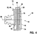
- the switching device 10 further comprises at least one locking unit 18 for locking the operating element 16 in at least one movement position of the operating element 16, in particular in at least one operating mode of the portable power tool 12 associated rotational position of the operating element 16 (see. FIGS. 1 . 4 . 5 and 6 ).
- the locking unit 18 has at least one movably mounted locking element 20 which, depending on a locking position of the locking element 20, triggers an electrical and / or electronic signal to a circuit of an operating mode of the portable power tool 12 (cf. FIGS. 2, 3 . 5 and 6 ).
- the locking element 20 is movably mounted on the control element 16. In particular, the locking element 20 is translationally movable on, in particular, mounted in the control element 16 (see. FIGS. 1 to 4 ).
- the operating element 16 has a bearing recess 74 in which the locking element 20 is movably mounted.
- a movement axis 48 of the locking element 20 extends transversely, in particular at least substantially perpendicular to the movement axis 68 of the operating element 16.
- the locking unit 18 comprises at least one spring element 76 which acts on the locking element 20 with a spring force acting in a direction away from the operating element 16 (cf. FIG. 4).
- the spring element 76 is designed in particular as a compression spring. However, it is also conceivable that the spring element 76 has another, a skilled person appear appropriate design, such as a design as a tension spring, a torsion spring o. The like.
- the spring element 76 is supported with one end on the control element 16 and with another End, the spring element 76 is supported on the locking element 20 from.
- the locking element 20 has a securing extension 78, which is provided to secure the locking element 20 on the operating element 16 against unintentional release of the operating element 16 (cf. FIG. 4 ).
- the securing extension 78 is designed as a latching extension, which cooperates with a latching projection 80 of the operating element 16. To allow disassembly of the locking element 20 of the control element 16, the securing extension 78 is elastically deflectable (see. FIG. 4 ).
- the mode selection unit 14 comprises at least one, in particular translational, movably mounted intermediate element 22, which is responsible for triggering an electrical and / or electronic signal to a circuit of an operating mode of the portable power tool 12 in response to a movement of the locking member 20 in at least one locking position of the locking element 20th by the locking element 20 is movable (see. FIGS. 2, 3 . 5 and 6 ).
- the intermediate element 22 is movable in response to a movement of the locking member 20 in at least one of a chisel operation of the portable power tool 12 associated locking position of the locking member 20 by the locking member 20.
- the intermediate element 22 is on the housing 52, in particular on the transmission housing, movable, in particular translationally movable, mounted.
- the intermediate element 22 is alternatively or in addition to the translationally movable mounting rotatably mounted on the housing 52, in particular on the transmission housing.
- a movement axis 34 of the intermediate element 22 extends at least substantially parallel to the main extension axis 70 of the portable power tool 12 and / or the impact axis 72 of the percussion mechanism unit 50.
- the movement axis 34 of the intermediate element 22 extends transversely, in particular at least substantially perpendicular, to the movement axis 68 of the operating element 16.
- the intermediate element 22 has at least three legs 38, 40, 42 which are angled relative to one another, wherein at least two of the three legs 38, 40, 42 extend at least substantially parallel to one another.
- the intermediate element 22 is preferably designed as a push rod, in particular as an angled push rod.
- the mode selection unit 14 has at least one spring element 26, which acts on the intermediate element 22 with a spring force in the direction of the locking element 20.
- the spring element 26 of the mode selector 14 is supported with at least one end on the intermediate element 22 and with another end, the intermediate member 22 is supported on the housing 52 or on an intermediate flange (not shown here) of the portable power tool 12.
- the locking unit 18 has at least one latching contour 24, which cooperates with the locking element 20 for locking the operating element 16 in at least one movement position of the operating element 16, wherein at least the intermediate element 22 at least partially in at least one state in the latching contour 24, in particular in at least one a chisel operation of the portable power tool 12 associated latching recess 82 of the locking contour 24, engages.
- the locking contour 24 is arranged on the housing 52, in particular on the transmission housing.
- the latching contour 24 comprises at least three latching recesses 82, 84, 86. A latching recess 82 of the three latching recesses 82, 84, 86 is associated with a chiseling operation of the portable power tool 12.
- a latching recess 84 of the three latching recesses 82, 84, 86 is associated with a hammer drill operation of the portable power tool 12.
- a latching recess 86 of the three latching recesses 82, 84, 86 is associated with a drilling operation of the portable power tool 12.
- the locking element 20 has at least one actuating surface 44 to a force of an operator force and at least one locking surface 46 which is arranged offset along the movement axis 48 of the locking member 20 relative to the actuating surface 44.
- the actuating surface 44 of the locking element 20 extends beyond an outer circumference of the operating element 16, at least in an unactuated state of the locking element 20.
- a comfortable actuation of the locking element 20 for a solution of a locking of the operating element 16 to a selection of an operating mode of the portable power tool 12 by a movement, in particular a rotational movement, of the operating element 16 are made possible.
- the locking surface 46 of the locking member 20 is provided depending on a movement position of the control element 16 in one of the recesses 82, 84, 86 engage, in particular engage, in particular to the control element 16 in at least one movement position, in particular in at least one operating mode associated movement position of the operating element 16, to lock.
- the intermediate element 22 engages in at least one state at least partially in the one chisel operation of the portable power tool 12 associated latching recess 82 of the latching contour 24 a.
- the locking surface 46 of the locking member 20 is at least partially from the chisel operation of the portable power tool 12 associated latching recess 82 of the locking contour 24 also movable (see. FIG. 6 ).
- the locking surface 46 of the locking element 20 preferably forms a contact surface 32 of the locking element 20 for a movement of the intermediate element 22.
- the intermediate element 22 has at least one contact surface 28, 30, in particular two mutually angled contact surfaces 28, 30, which leads to a movement of the intermediate element 22nd in response to a movement of the locking member 20 cooperates in at least one locking position of the locking member 20 with the corresponding contact surface 32 of the locking member 20.
- the contact surface 28, 30 of the intermediate element 22 includes with the movement axis 34 of the intermediate member 22 a deviating from 90 ° angle 36 a.
- a sudden movement of the intermediate element 22 can be largely avoided.
- a smooth transition from a position of the intermediate element 22 to a further position in which a switching element 88 of the switching device 10 can be actuated by means of the intermediate element 22 can be achieved ( FIGS. 2 and 3 ).
- the intermediate element 22 is intended to cooperate directly with the switching element 88 of the switching device 10, in particular with an end of the intermediate element 22 facing away from the locking element 20.
- the switching element 88 is preferably designed as a Hall sensor.
- Arranged on the intermediate element 22 is preferably a magnetic element 90, in particular a permanent magnet, which is intended to cooperate in triggering an electrical and / or electronic signal with the Hall sensor in a manner already known to a person skilled in the art.
- the switching element 88 can be designed as an electrical switch, in particular as a microswitch, as an inductive proximity sensor, as a light barrier or as another switching element that appears meaningful to a person skilled in the art, which can be actuated by means of a movement of the intermediate element 22.
- the inventive design of the switching device 10 can be advantageously ensured that due to a secure latching of the locking member 20 in the locking contour 24 reliable triggering of an electrical and / or electronic signal to a circuit of an operating mode of the portable power tool 12 is realized.
Landscapes
- Engineering & Computer Science (AREA)
- Mechanical Engineering (AREA)
- Percussive Tools And Related Accessories (AREA)
Applications Claiming Priority (1)
| Application Number | Priority Date | Filing Date | Title |
|---|---|---|---|
| DE102016218535.7A DE102016218535A1 (de) | 2016-09-27 | 2016-09-27 | Schaltvorrichtung für eine tragbare Werkzeugmaschine, insbesondere einen Bohr- und/oder Meißelhammer |
Publications (2)
| Publication Number | Publication Date |
|---|---|
| EP3305471A1 true EP3305471A1 (fr) | 2018-04-11 |
| EP3305471B1 EP3305471B1 (fr) | 2025-11-05 |
Family
ID=59829267
Family Applications (1)
| Application Number | Title | Priority Date | Filing Date |
|---|---|---|---|
| EP17190063.2A Active EP3305471B1 (fr) | 2016-09-27 | 2017-09-08 | Machine-outil portable, en particulier un marteau perforateur et/ou un marteau burineur |
Country Status (3)
| Country | Link |
|---|---|
| US (1) | US10786893B2 (fr) |
| EP (1) | EP3305471B1 (fr) |
| DE (1) | DE102016218535A1 (fr) |
Families Citing this family (9)
| Publication number | Priority date | Publication date | Assignee | Title |
|---|---|---|---|---|
| DE102016218535A1 (de) * | 2016-09-27 | 2018-03-29 | Robert Bosch Gmbh | Schaltvorrichtung für eine tragbare Werkzeugmaschine, insbesondere einen Bohr- und/oder Meißelhammer |
| DE102018208048A1 (de) * | 2018-05-23 | 2019-11-28 | Robert Bosch Gmbh | Handwerkzeugmaschine |
| EP3581337A1 (fr) * | 2018-06-11 | 2019-12-18 | HILTI Aktiengesellschaft | Machine-outil portative |
| EP3593951A1 (fr) * | 2018-07-11 | 2020-01-15 | Hilti Aktiengesellschaft | Machine-outil portative |
| JP7601555B2 (ja) * | 2020-02-03 | 2024-12-17 | 株式会社マキタ | ハンマドリル |
| US12587195B2 (en) * | 2021-03-04 | 2026-03-24 | Snap-On Incorporated | Non-contact direction selector mechanism |
| EP4257293A1 (fr) | 2022-04-08 | 2023-10-11 | Milwaukee Electric Tool Corporation | Perforateur rotatif |
| US12397404B2 (en) * | 2023-05-30 | 2025-08-26 | Milwaukee Electric Tool Corporation | Operating mode detection system for rotary hammer |
| US12465385B1 (en) * | 2025-04-29 | 2025-11-11 | Dixing Chen | Foot repair device |
Citations (11)
| Publication number | Priority date | Publication date | Assignee | Title |
|---|---|---|---|---|
| WO1988006508A2 (fr) | 1987-03-05 | 1988-09-07 | Robert Bosch Gmbh | Procede d'interruption de l'entrainement, en particulier en percussion et/ou en rotation, d'un outil a main |
| EP0612588A1 (fr) * | 1993-02-26 | 1994-08-31 | Kress-elektrik GmbH + Co. Elektromotorenfabrik | Dispositif de commande pour outils électriques |
| GB2285764A (en) * | 1994-01-21 | 1995-07-26 | Bosch Gmbh Robert | Hammer drill speed controller |
| EP0666148A1 (fr) | 1993-12-28 | 1995-08-09 | HILTI Aktiengesellschaft | Procédé et dispositif pour machines portatives pour éviter des accidents causés par un blocage d'outil |
| GB2314288A (en) * | 1996-06-15 | 1997-12-24 | Bosch Gmbh Robert | Electric combination hammer |
| DE19641618A1 (de) | 1996-10-09 | 1998-04-30 | Hilti Ag | Einrichtung und Verfahren für handgeführte Werkzeugmaschinen zur Vermeidung von Unfällen durch Werkzeugblockieren |
| EP1080849A2 (fr) * | 1999-09-03 | 2001-03-07 | HILTI Aktiengesellschaft | Dispositif de commutation pour foreuse portable multi-fonctionelle |
| DE102005059182A1 (de) * | 2005-12-12 | 2007-06-14 | Robert Bosch Gmbh | Betriebsartenumschalter zum Einstellen mindestens einer Betriebsart in einer Handwerkzeugmaschine |
| EP2062670A2 (fr) * | 2007-11-21 | 2009-05-27 | Black & Decker, Inc. | Perceuse à modes multiples dotée d'un agencement de commutation électronique |
| EP2481526A1 (fr) * | 2011-02-01 | 2012-08-01 | Makita Corporation | Outil électrique |
| DE202013001457U1 (de) * | 2013-02-14 | 2013-02-22 | Robert Bosch Gmbh | Handwerkzeugmaschinenschaltvorrichtung |
Family Cites Families (18)
| Publication number | Priority date | Publication date | Assignee | Title |
|---|---|---|---|---|
| US4204580A (en) * | 1978-08-03 | 1980-05-27 | The Singer Company | Forward biased switch for a reversible hammer drill |
| DE19937767B4 (de) * | 1999-08-10 | 2004-09-09 | Hilti Ag | Handgeführter elektrischer Kombihammer |
| GB0311045D0 (en) * | 2003-05-14 | 2003-06-18 | Black & Decker Inc | Rotary hammer |
| JP4509662B2 (ja) * | 2004-06-16 | 2010-07-21 | 株式会社マキタ | 電動打撃工具 |
| DE102004057686A1 (de) * | 2004-11-30 | 2006-06-01 | Robert Bosch Gmbh | Schaltvorrichtung |
| DE102005041448A1 (de) * | 2005-08-31 | 2007-03-01 | Robert Bosch Gmbh | Handbohrmaschine mit Schaltgetriebe |
| DE102006000287A1 (de) * | 2006-06-09 | 2007-12-13 | Hilti Ag | Handwerkzeuggerät mit Vibrationsminderungseinrichtung |
| DE102006059078A1 (de) * | 2006-12-14 | 2008-06-19 | Robert Bosch Gmbh | Elektrogerät mit aufgerastetem drehbarem Bedienungselement |
| DE102007010180A1 (de) * | 2007-03-02 | 2008-09-04 | Robert Bosch Gmbh | Handwerkzeugmaschine |
| DE102007000362A1 (de) * | 2007-07-02 | 2009-01-08 | Hilti Aktiengesellschaft | Vibrierende Handwerkzeugmaschine mit einem Arretierschalter des Motorschalters |
| DE102007000470A1 (de) * | 2007-08-29 | 2009-03-05 | Hilti Aktiengesellschaft | Vibrierende Handwerkzeugmaschine mit einem Arretierschalter des Motorschalters |
| GB201413293D0 (en) * | 2014-07-28 | 2014-09-10 | Black & Decker Inc | Mode change knob assembly |
| EP3023202A1 (fr) * | 2014-11-20 | 2016-05-25 | HILTI Aktiengesellschaft | Procédé de sécurité et machine-outil manuelle |
| GB2532980A (en) * | 2014-12-04 | 2016-06-08 | Black & Decker Inc | Planetary gear system |
| DE102015226440A1 (de) * | 2015-12-22 | 2017-06-22 | Robert Bosch Gmbh | Handwerkzeugmaschinenvorrichtung |
| DE102016218535A1 (de) * | 2016-09-27 | 2018-03-29 | Robert Bosch Gmbh | Schaltvorrichtung für eine tragbare Werkzeugmaschine, insbesondere einen Bohr- und/oder Meißelhammer |
| JP6912224B2 (ja) * | 2017-03-03 | 2021-08-04 | 株式会社マキタ | 作業工具 |
| EP3461596B1 (fr) * | 2017-09-15 | 2023-02-22 | Black & Decker Inc. | Extracteur de fumée |
-
2016
- 2016-09-27 DE DE102016218535.7A patent/DE102016218535A1/de not_active Withdrawn
-
2017
- 2017-09-08 EP EP17190063.2A patent/EP3305471B1/fr active Active
- 2017-09-22 US US15/713,381 patent/US10786893B2/en active Active
Patent Citations (12)
| Publication number | Priority date | Publication date | Assignee | Title |
|---|---|---|---|---|
| WO1988006508A2 (fr) | 1987-03-05 | 1988-09-07 | Robert Bosch Gmbh | Procede d'interruption de l'entrainement, en particulier en percussion et/ou en rotation, d'un outil a main |
| EP0612588A1 (fr) * | 1993-02-26 | 1994-08-31 | Kress-elektrik GmbH + Co. Elektromotorenfabrik | Dispositif de commande pour outils électriques |
| EP0666148A1 (fr) | 1993-12-28 | 1995-08-09 | HILTI Aktiengesellschaft | Procédé et dispositif pour machines portatives pour éviter des accidents causés par un blocage d'outil |
| DE4344817C2 (de) | 1993-12-28 | 1995-11-16 | Hilti Ag | Verfahren und Einrichtung für handgeführte Werkzeugmaschinen zur Vermeidung von Unfällen durch Werkzeugblockieren |
| GB2285764A (en) * | 1994-01-21 | 1995-07-26 | Bosch Gmbh Robert | Hammer drill speed controller |
| GB2314288A (en) * | 1996-06-15 | 1997-12-24 | Bosch Gmbh Robert | Electric combination hammer |
| DE19641618A1 (de) | 1996-10-09 | 1998-04-30 | Hilti Ag | Einrichtung und Verfahren für handgeführte Werkzeugmaschinen zur Vermeidung von Unfällen durch Werkzeugblockieren |
| EP1080849A2 (fr) * | 1999-09-03 | 2001-03-07 | HILTI Aktiengesellschaft | Dispositif de commutation pour foreuse portable multi-fonctionelle |
| DE102005059182A1 (de) * | 2005-12-12 | 2007-06-14 | Robert Bosch Gmbh | Betriebsartenumschalter zum Einstellen mindestens einer Betriebsart in einer Handwerkzeugmaschine |
| EP2062670A2 (fr) * | 2007-11-21 | 2009-05-27 | Black & Decker, Inc. | Perceuse à modes multiples dotée d'un agencement de commutation électronique |
| EP2481526A1 (fr) * | 2011-02-01 | 2012-08-01 | Makita Corporation | Outil électrique |
| DE202013001457U1 (de) * | 2013-02-14 | 2013-02-22 | Robert Bosch Gmbh | Handwerkzeugmaschinenschaltvorrichtung |
Also Published As
| Publication number | Publication date |
|---|---|
| US10786893B2 (en) | 2020-09-29 |
| DE102016218535A1 (de) | 2018-03-29 |
| EP3305471B1 (fr) | 2025-11-05 |
| US20180085906A1 (en) | 2018-03-29 |
Similar Documents
| Publication | Publication Date | Title |
|---|---|---|
| EP3305471B1 (fr) | Machine-outil portable, en particulier un marteau perforateur et/ou un marteau burineur | |
| EP0224010B1 (fr) | Outil portatif à moteur pour perçage avec ou sans percussion | |
| DE19944294B4 (de) | Fremdkraftgetriebener Bohrhammer mit verbessertem Betriebsmodusumschalter | |
| EP1080849B1 (fr) | Dispositif de commutation pour foreuse portable multi-fonctionelle | |
| EP1379362B1 (fr) | Machine-outil a main | |
| DE19540718B4 (de) | Handwerkzeugmaschine mit einer von einer Detektionseinrichtung auslösbaren Blockiereinrichtung | |
| DE10130548B4 (de) | Zusatzhandgriff | |
| EP2448715B1 (fr) | Machine-outil portative | |
| EP2129496B1 (fr) | Machine-outil portative | |
| EP2448717B1 (fr) | Machine-outil portative | |
| EP2797721B1 (fr) | Dispositif pour outil manuel | |
| DE102004012433A1 (de) | Handwerkzeugmaschine | |
| EP1282484A1 (fr) | Machine-outil, notamment machine-outil a main | |
| EP2612732A1 (fr) | Dispositif d'outil manuel | |
| EP1436124A1 (fr) | Machine-outil a main | |
| DE4401664B4 (de) | Bohrhammer mit einer elektronischen Regeleinrichtung und einem Betriebsartenschalter | |
| EP2612731B1 (fr) | Dispositif d'outil manuel | |
| EP2612730B1 (fr) | Dispositif d'outil manuel | |
| EP2709801B1 (fr) | Porte-outils | |
| DE102004017940A1 (de) | Schlagwerk für eine Handwerkzeugmaschine | |
| EP1632313B1 (fr) | Outil de serrage avec mécanisme d'impact axial | |
| EP2140982A1 (fr) | Marteau perforateur et/ou marteau-piqueur | |
| DE102016218775A1 (de) | Handwerkzeugmaschinensystem | |
| DE4020242C2 (de) | Bohrmaschine, insbesondere zur Erzeugung von Ausnehmungen in Wänden, zur Unterbringung von elektrischen Installationsdosen | |
| DE202013001457U1 (de) | Handwerkzeugmaschinenschaltvorrichtung |
Legal Events
| Date | Code | Title | Description |
|---|---|---|---|
| PUAI | Public reference made under article 153(3) epc to a published international application that has entered the european phase |
Free format text: ORIGINAL CODE: 0009012 |
|
| STAA | Information on the status of an ep patent application or granted ep patent |
Free format text: STATUS: THE APPLICATION HAS BEEN PUBLISHED |
|
| AK | Designated contracting states |
Kind code of ref document: A1 Designated state(s): AL AT BE BG CH CY CZ DE DK EE ES FI FR GB GR HR HU IE IS IT LI LT LU LV MC MK MT NL NO PL PT RO RS SE SI SK SM TR |
|
| AX | Request for extension of the european patent |
Extension state: BA ME |
|
| STAA | Information on the status of an ep patent application or granted ep patent |
Free format text: STATUS: REQUEST FOR EXAMINATION WAS MADE |
|
| 17P | Request for examination filed |
Effective date: 20181011 |
|
| RBV | Designated contracting states (corrected) |
Designated state(s): AL AT BE BG CH CY CZ DE DK EE ES FI FR GB GR HR HU IE IS IT LI LT LU LV MC MK MT NL NO PL PT RO RS SE SI SK SM TR |
|
| RAP1 | Party data changed (applicant data changed or rights of an application transferred) |
Owner name: ROBERT BOSCH GMBH |
|
| STAA | Information on the status of an ep patent application or granted ep patent |
Free format text: STATUS: EXAMINATION IS IN PROGRESS |
|
| 17Q | First examination report despatched |
Effective date: 20200723 |
|
| GRAP | Despatch of communication of intention to grant a patent |
Free format text: ORIGINAL CODE: EPIDOSNIGR1 |
|
| STAA | Information on the status of an ep patent application or granted ep patent |
Free format text: STATUS: GRANT OF PATENT IS INTENDED |
|
| INTG | Intention to grant announced |
Effective date: 20250616 |
|
| GRAS | Grant fee paid |
Free format text: ORIGINAL CODE: EPIDOSNIGR3 |
|
| GRAA | (expected) grant |
Free format text: ORIGINAL CODE: 0009210 |
|
| STAA | Information on the status of an ep patent application or granted ep patent |
Free format text: STATUS: THE PATENT HAS BEEN GRANTED |
|
| AK | Designated contracting states |
Kind code of ref document: B1 Designated state(s): AL AT BE BG CH CY CZ DE DK EE ES FI FR GB GR HR HU IE IS IT LI LT LU LV MC MK MT NL NO PL PT RO RS SE SI SK SM TR |
|
| REG | Reference to a national code |
Ref country code: CH Ref legal event code: F10 Free format text: ST27 STATUS EVENT CODE: U-0-0-F10-F00 (AS PROVIDED BY THE NATIONAL OFFICE) Effective date: 20251105 Ref country code: GB Ref legal event code: FG4D Free format text: NOT ENGLISH |
|
| REG | Reference to a national code |
Ref country code: DE Ref legal event code: R096 Ref document number: 502017017118 Country of ref document: DE |
|
| REG | Reference to a national code |
Ref country code: IE Ref legal event code: FG4D Free format text: LANGUAGE OF EP DOCUMENT: GERMAN |
|
| REG | Reference to a national code |
Ref country code: NL Ref legal event code: MP Effective date: 20251105 |
|
| PG25 | Lapsed in a contracting state [announced via postgrant information from national office to epo] |
Ref country code: ES Free format text: LAPSE BECAUSE OF FAILURE TO SUBMIT A TRANSLATION OF THE DESCRIPTION OR TO PAY THE FEE WITHIN THE PRESCRIBED TIME-LIMIT Effective date: 20251105 |
|
| REG | Reference to a national code |
Ref country code: LT Ref legal event code: MG9D |
|
| PG25 | Lapsed in a contracting state [announced via postgrant information from national office to epo] |
Ref country code: NO Free format text: LAPSE BECAUSE OF FAILURE TO SUBMIT A TRANSLATION OF THE DESCRIPTION OR TO PAY THE FEE WITHIN THE PRESCRIBED TIME-LIMIT Effective date: 20260205 |
|
| PG25 | Lapsed in a contracting state [announced via postgrant information from national office to epo] |
Ref country code: FI Free format text: LAPSE BECAUSE OF FAILURE TO SUBMIT A TRANSLATION OF THE DESCRIPTION OR TO PAY THE FEE WITHIN THE PRESCRIBED TIME-LIMIT Effective date: 20251105 Ref country code: HR Free format text: LAPSE BECAUSE OF FAILURE TO SUBMIT A TRANSLATION OF THE DESCRIPTION OR TO PAY THE FEE WITHIN THE PRESCRIBED TIME-LIMIT Effective date: 20251105 |
|
| PG25 | Lapsed in a contracting state [announced via postgrant information from national office to epo] |
Ref country code: NL Free format text: LAPSE BECAUSE OF FAILURE TO SUBMIT A TRANSLATION OF THE DESCRIPTION OR TO PAY THE FEE WITHIN THE PRESCRIBED TIME-LIMIT Effective date: 20251105 |
|
| PG25 | Lapsed in a contracting state [announced via postgrant information from national office to epo] |
Ref country code: RS Free format text: LAPSE BECAUSE OF FAILURE TO SUBMIT A TRANSLATION OF THE DESCRIPTION OR TO PAY THE FEE WITHIN THE PRESCRIBED TIME-LIMIT Effective date: 20260205 |
|
| PG25 | Lapsed in a contracting state [announced via postgrant information from national office to epo] |
Ref country code: IS Free format text: LAPSE BECAUSE OF FAILURE TO SUBMIT A TRANSLATION OF THE DESCRIPTION OR TO PAY THE FEE WITHIN THE PRESCRIBED TIME-LIMIT Effective date: 20260305 |
|
| PG25 | Lapsed in a contracting state [announced via postgrant information from national office to epo] |
Ref country code: PT Free format text: LAPSE BECAUSE OF FAILURE TO SUBMIT A TRANSLATION OF THE DESCRIPTION OR TO PAY THE FEE WITHIN THE PRESCRIBED TIME-LIMIT Effective date: 20260305 |
|
| PG25 | Lapsed in a contracting state [announced via postgrant information from national office to epo] |
Ref country code: PL Free format text: LAPSE BECAUSE OF FAILURE TO SUBMIT A TRANSLATION OF THE DESCRIPTION OR TO PAY THE FEE WITHIN THE PRESCRIBED TIME-LIMIT Effective date: 20251105 |
|
| PG25 | Lapsed in a contracting state [announced via postgrant information from national office to epo] |
Ref country code: LV Free format text: LAPSE BECAUSE OF FAILURE TO SUBMIT A TRANSLATION OF THE DESCRIPTION OR TO PAY THE FEE WITHIN THE PRESCRIBED TIME-LIMIT Effective date: 20251105 |
|
| PG25 | Lapsed in a contracting state [announced via postgrant information from national office to epo] |
Ref country code: BG Free format text: LAPSE BECAUSE OF FAILURE TO SUBMIT A TRANSLATION OF THE DESCRIPTION OR TO PAY THE FEE WITHIN THE PRESCRIBED TIME-LIMIT Effective date: 20251105 |