EP3305584A1 - Sitzunterlage - Google Patents
Sitzunterlage Download PDFInfo
- Publication number
- EP3305584A1 EP3305584A1 EP16799708.9A EP16799708A EP3305584A1 EP 3305584 A1 EP3305584 A1 EP 3305584A1 EP 16799708 A EP16799708 A EP 16799708A EP 3305584 A1 EP3305584 A1 EP 3305584A1
- Authority
- EP
- European Patent Office
- Prior art keywords
- seat pad
- lateral
- lateral direction
- lateral slit
- thickness direction
- Prior art date
- Legal status (The legal status is an assumption and is not a legal conclusion. Google has not performed a legal analysis and makes no representation as to the accuracy of the status listed.)
- Granted
Links
Images

Classifications
-
- A—HUMAN NECESSITIES
- A47—FURNITURE; DOMESTIC ARTICLES OR APPLIANCES; COFFEE MILLS; SPICE MILLS; SUCTION CLEANERS IN GENERAL
- A47C—CHAIRS; SOFAS; BEDS
- A47C7/00—Parts, details, or accessories of chairs or stools
- A47C7/02—Seat parts
- A47C7/18—Seat parts having foamed material included in cushioning part
-
- B—PERFORMING OPERATIONS; TRANSPORTING
- B60—VEHICLES IN GENERAL
- B60N—SEATS SPECIALLY ADAPTED FOR VEHICLES; VEHICLE PASSENGER ACCOMMODATION NOT OTHERWISE PROVIDED FOR
- B60N2/00—Seats specially adapted for vehicles; Arrangement or mounting of seats in vehicles
- B60N2/70—Upholstery springs ; Upholstery
-
- A—HUMAN NECESSITIES
- A47—FURNITURE; DOMESTIC ARTICLES OR APPLIANCES; COFFEE MILLS; SPICE MILLS; SUCTION CLEANERS IN GENERAL
- A47C—CHAIRS; SOFAS; BEDS
- A47C27/00—Spring, stuffed or fluid mattresses or cushions specially adapted for chairs, beds or sofas
- A47C27/14—Spring, stuffed or fluid mattresses or cushions specially adapted for chairs, beds or sofas with foamed material inlays
-
- B—PERFORMING OPERATIONS; TRANSPORTING
- B60—VEHICLES IN GENERAL
- B60N—SEATS SPECIALLY ADAPTED FOR VEHICLES; VEHICLE PASSENGER ACCOMMODATION NOT OTHERWISE PROVIDED FOR
- B60N2/00—Seats specially adapted for vehicles; Arrangement or mounting of seats in vehicles
- B60N2/64—Back-rests or cushions
- B60N2/646—Back-rests or cushions shape of the cushion
-
- B—PERFORMING OPERATIONS; TRANSPORTING
- B60—VEHICLES IN GENERAL
- B60N—SEATS SPECIALLY ADAPTED FOR VEHICLES; VEHICLE PASSENGER ACCOMMODATION NOT OTHERWISE PROVIDED FOR
- B60N2/00—Seats specially adapted for vehicles; Arrangement or mounting of seats in vehicles
- B60N2/90—Details or parts not otherwise provided for
-
- B—PERFORMING OPERATIONS; TRANSPORTING
- B68—SADDLERY; UPHOLSTERY
- B68G—METHODS, EQUIPMENT, OR MACHINES FOR USE IN UPHOLSTERING; UPHOLSTERY NOT OTHERWISE PROVIDED FOR
- B68G5/00—Resilient upholstery pads
- B68G5/02—Resilient upholstery pads of cellular material, e.g. sponge rubber
Definitions
- the present invention relates to a seat pad.
- Patent Document 1 a seat pad disclosed in Patent Document 1 below is known.
- Patent Document 1 Japanese Unexamined Patent Application, First Publication No. 2006-149466
- the present invention is made in consideration of the above-described circumstances, and an object thereof is to improve the comfortable feeling.
- the present invention suggests the following means.
- a seat pad which includes a placement surface, in which a lateral slit portion which extends from an outer side of the seat pad toward an inner side thereof is formed in a first lateral direction along the placement surface, and at least a portion of the lateral slit portion gradually becomes larger from the outer side of the seat pad toward the inner side thereof in a thickness direction orthogonal to the placement surface along the first lateral direction.
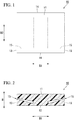
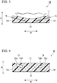
- FIGS. 1 to 3 a seat pad 10 according to a first embodiment of the present invention will be described with reference to FIGS. 1 to 3 .
- the seat pad 10 is formed of a foamed molded body.
- the foamed molded body a soft resin foamed molded body formed by foaming a resin material, for example, soft polyurethane foam (soft resin), or the like can be mentioned.
- the seat pad 10 is integrally formed of the same material.
- the seat pad 10 is adopted for a seat attached to an automobile (vehicle).
- the seat pad 10 includes a seating surface 11 (placement surface) which contacting an occupant who sits on the seat.
- the seat pad 10 can be applied to a cushion pad or a back pad.
- the seating surface 11 faces the upper side in a vertical direction and a load of the occupant is applied to the seat pad 10 from the upper side.
- the seating surface 11 faces the front side of the automobile and the load of the occupant is applied to the seat pad 10 from the front side.
- the seat pad 10 is formed in a flat rectangular parallelepiped shape and a direction orthogonal to the seating surface 11 in the seat pad 10 is a thickness direction H of the seat pad 10.
- a surface facing a side (a side opposite to the placement surface) opposite to the seating surface in the thickness direction H is an attachment surface 12 (rear surface) of the seat pad 10.
- the seat pad 10 is formed in a rectangular shape which extends in a first lateral direction B1 and a second lateral direction B2 (regulation direction) orthogonal to each other along the seating surface 11 in a plan view of the seat pad 10.
- First side surfaces 13 which extend in a direction orthogonal to the first lateral direction B1 and second side surfaces 14 which extend in a direction orthogonal to the second lateral direction B2 are provided on side surfaces of the seat pad 10.
- the first lateral direction B1 may be right and left directions of an automobile or may be front and rear directions of a vehicle.
- lateral slit portions 15 which extend from the outer side of the seat pad 10 toward the inner side thereof along the first lateral direction B1 are formed.
- the lateral slit portions 15 are provided at portions positioned on both sides of the seat pad 10 in the first lateral direction B1, and are not provided at a center portion in the first lateral direction B1.
- Each of the lateral slit portions 15 extends from the outer side of the seat pad 10 toward the inner side thereof in a plan view of the seat pad 10.
- An outer end portion of the lateral slit portion 15 in the first lateral direction B1 is open to the surface of the seat pad 10, and an inner end portion of the lateral slit portion 15 in the first lateral direction B1 is not open to the surface of the seat pad 10.
- Each of the lateral slit portions 15 is open to the first side surface 13 and extends from the first side surface 13 toward the inside in the first lateral direction B1.
- Sizes of the lateral slit portions 15 in the first lateral direction B1 are the same as each other over the entire length in the second lateral direction B2.
- Each of the lateral slit portions 15 is smaller than the seat pad 10 in the second lateral direction B2 and is not open to the second side surface 14.
- the size of the lateral slit portion 15 in the second lateral direction B2 is approximately 10 to 25 mm.
- the lateral slit portions 15 gradually extend toward the side opposite to the seating surface in the thickness direction H toward the inside in the first lateral direction B1. At least a portion of each of the lateral slit portions 15 gradually becomes larger in the thickness direction H from the outer side of the seat pad 10 toward the inner side thereof along the first lateral direction B1. In the example shown, the lateral slit portion 15 gradually becomes larger in the thickness direction H from the outer side of the seat pad 10 toward the inner side thereof over the entire length in the first lateral direction B1. In a sectional view when the seat pad 10 is viewed from the second lateral direction B2, the lateral slit portion 15 is formed in a triangular shape which protrudes toward the outside in the first lateral direction B1.
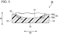
- the lateral slit portions 15 which extend from the outer side of the seat pad 10 toward the inner side thereof along the first lateral direction B1 are formed in the seat pad 10. Accordingly, as shown in FIG. 3 , when an occupant sits on the seating surface 11, the seat pad 10 is deformed such that the lateral slit portions 15 are narrowed in the thickness direction H. Therefore, the seat pad 10 can be appropriately bent while suppressing a hardness which an occupant feels from the seat pad 10, and thus, it is possible to improve a comfortable feeling when the occupant sits on the seat pad or when a vehicle travels around a corner.
- each of the lateral slit portions 15 gradually becomes larger in the thickness direction H from the outer side of the seat pad 10 toward the inner side thereof along the first lateral direction B1. Accordingly, in the seating surface 11, compared to a portion positioned in the outer portion of the seat pad 10, it is possible to positively deform a portion positioned in the inner portion of the seat pad 10 to which a load is easily applied when an occupant sits on the seat pad. Accordingly, for example, even when adjustment or the like of a size of the seat pad 10 in the thickness direction H is not performed, the seat pad 10 can be deformed so as to enfold the occupant on the seating surface 11 from the outside in the first lateral direction B1, and it is possible to further improve a comfortable feeling.
- each of the lateral slit portions 15 gradually becomes larger in the thickness direction H from the outer side of the seat pad 10 toward the inner side thereof over the entire length in the first lateral direction B1. Accordingly, the degree of deformation of the seat pad 10 can be gradually changed along the first lateral direction B1, and thus, it is possible to effectively prevent discomfort from occurring when the seat pad 10 is bent.
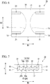
- a steep slope portion 15a positioned in the outer portion in the first lateral direction B1 and a gentle slope portion 15b positioned in the inner portion in the first lateral direction B1 are connected to each other in the first lateral direction B1.
- Each of the lateral slit portions 15 is open to the seating surface 11.
- an end portion, which is a portion opened to the seating surface 11 and is positioned in the outer portion of the lateral slit portion 15 in the first lateral direction B1 is positioned outside a portion of the seating surface 11, which contacting the occupant, in the first lateral direction B1.
- the portion which contacting the occupant is adjacent to the outer portion in the first lateral direction B1.
- FIGS. 6 to 8 a seat pad 70 of a third embodiment according to the present invention will be described with reference to FIGS. 6 to 8 .
- the lateral slit portions 15 are gradually lengthened in the first lateral direction B1 from the outer portion toward the inner portion along the second lateral direction B2.
- An inner end portion of each of the lateral slit portion 15 in the first lateral direction B1 is curved to protrude toward the inner side in the first lateral direction B1 in a plan view of the seat portion 70.
- each of the lateral slit portions 15 is curved to protrude in the thickness direction H.
- the lateral slit portion 15 is curved to protrude toward the side opposite to the seating surface along the thickness direction H.
- the inner end portion of the lateral slit portion 15 in the first lateral direction B1 is positioned to be closer to the side opposite to the seating surface along the thickness direction H than the outer end portion of the lateral slit portion 15 in the first lateral direction B1.
- the lateral slit portions 15 are curved according to an outline of an occupant who sits on a seat.
- an uneven portion 18 continuous in the second lateral direction B2 is formed on each of a first inner surface 16 positioned on the seating surface 11 side along the thickness direction H and a second inner surface 17 positioned on the side opposite to the seating surface along the thickness direction H.
- Recessed portions 18a and protrusion portions 18b which configure the uneven portion 18 extend in the first lateral direction B1.
- Each of the recessed portions 18a and the protrusion portions 18b are formed in a triangular shape in a front view when viewed in the first lateral direction B1.
- wave shapes formed by the surfaces of each of the first and second uneven portions 19 and 20 have the same shape as each other.
- periods thereof along the second lateral direction B2 are the same as each other and amplitudes thereof along the thickness direction H are the same as each other.
- the recessed portions 18a and the protrusion portions 18b thereof face each other in the thickness direction H.
- vertical slit portions 21 which extend from each of the lateral slit portions 15 toward the seating surface 11 side along the thickness direction H are provided on end portions of each of the lateral slit portions 15 in the second lateral direction B2.
- the vertical slit portions 21 are provided on both end portions of each of the lateral slit portions 15 in the second lateral direction B2.
- the vertical slit portions 21 are formed over the entire length of the lateral slit portion 15 in the first lateral direction B1.
- Each of the vertical slit portions 21 is formed in a linear shape which extends in the first lateral direction B1 in a plan view of the seat pad 70.
- the vertical slit portions 21 extend from the lateral slit portion 15 to the seating surface 11 and are open to the seating surface 11 over the entire length of the lateral slit portion 15 in the first lateral direction B 1.
- the lateral slit portions 15 are curved to protrude in the thickness direction H, and thus, the lateral slit portions 15 can easily follow the outline of the occupant who sits on the seating surface 11. Accordingly, the seat pad 70 can be bent along the outline of the occupant, a fit feeling increases, and thus, it is possible to improve a comfortable feeling.
- the seat pad 70 can be effectively bent along the outline of the occupant, a fit feeling increases, and it is possible to improve a comfortable feeling.
- the vertical slit portions 21 are provided on end portions of each of the lateral slit portions 15 in the second lateral direction B2. Accordingly, when the occupant sits on the seating surface 11, a portion (hereinafter, referred to as a "pressure receiving deformation portion") positioned between the seating surface 11 and each of the lateral slit portions 15 in the seat pad 70 is elongated to be deformed toward the outside in the second lateral direction B2 such that the vertical slit portion 21 is narrowed in the second lateral direction B2. Accordingly, the seat pad 70 can be deformed to enfold the occupant on the seating surface 11 from the outside in the second lateral direction B2, and thus, it is possible to further improve a comfortable feeling.
- a portion hereinafter, referred to as a "pressure receiving deformation portion”
- the pressure receiving deformation portions of the seat pad 70 can be easily deformed independently of other portions. Accordingly, when a core which forms each of the lateral slit portions 15 in a mold forming the seat pad 70 is removed from the seat pad 70, it is possible to positively deform the pressure receiving deformation portions to prevent an excessive load from being applied to the pressure receiving deformation portions, and thus, it is possible to easily and accurately form the seat pad 70.
- the recessed portions 18a and the protrusion portions 18b of both portions face each other in the thickness direction H. Accordingly, when an occupant sits on the seating surface 11 and the lateral slit portions 15 are narrowed in the thickness direction H, the first uneven portion 19 and the second uneven portion 20 can be fitted to each other.
- portions of positioned on both sides in a state where the lateral slit portion 15 is interposed therebetween in the thickness direction H can be prevented from being displaced to relative to each other in the second lateral direction B2 when an occupant sits on the seat pad, and thus, it is possible to further improve a comfortable feeling.
- each of the lateral slit portions 15 is gradually lengthened in the first lateral direction B1 from the outer portion toward the inner portion along the second lateral direction B2. Accordingly, in the seating surface 11, compared to the portions positioned on both end portions of each lateral slit portion 15 in the second lateral direction B2, it is possible to positively deform a portion positioned at a center portion of each lateral slit portion 15 in the second lateral direction B2. Accordingly, the seat pad 70 can be deformed to enfold the occupant on the seating surface 11 from the outside in the second lateral direction B2, and thus, it is possible to further improve a comfortable feeling.
- the seat pad 90 according to the present embodiment is integrally formed of materials different from each other, and in the example shown, layers 91 and 92 having harnesses different from each other are laminated in the thickness direction H.
- the seat pad 90 includes a base layer 91 on the attachment surface 12 side and a cushion layer 92 on the seating surface 11 side.
- the base layer 91 and the cushion layer 92 are partitioned by the lateral slit portions 15 in the thickness direction H, and in the seat pad 90, the portion positioned on the attachment surface 12 side from the lateral slit portions 15 becomes the base layer 91, and the portion positioned on the seating surface 11 side from the lateral slit portions 15 becomes the cushion layer 92.
- the seating surface 11 is formed of the cushion layer 92, and thus, the hardness of the cushion layer 92 is lower than the hardness of the base layer 91.
- the base layer 91 is disposed to be limited to both sides in the first lateral direction B1, and the center portion in the first lateral direction B1 is configured of the cushion layer 92. That is, in a sectional view when the seat pad 10 is viewed in the second lateral direction B2, the cushion layer 92 is formed in a T shape which protrudes toward the attachment surface 12 side. In the cushion layer 92, the portion protruding toward the attachment surface 12 side is connected to the base layers 91 from both sides in the first lateral direction B1.
- the base layers 91 and the cushion layer 92 are partitioned by the lateral slit portions 15 in the thickness direction H. Therefore, when an occupant sits on the seating surface 11 and the cushion layer 92 is deformed, it is possible to prevent the base layers 91 from being deformed to follow the cushion layer 92. Accordingly, it is possible to easily exert characteristics of the layers 91 and 92.
- the lateral slit portions 15 are provided on the portions positioned on both sides of the seat pad 10 in the first lateral direction B1. Accordingly, when an occupant sits on the seat pad, in the center portion of the seating surface 11, to which a load is easily applied, in the first lateral direction B1, it is possible to prevent a feeling of tightness (discomfort) from occurring. Accordingly, it is possible to more easily exert characteristics of the layers 91 and 92.
- the hardness of the cushion layer 92 is lower than the hardness of the base layer 91 such that characteristics of the layers 91 and 92 can be more easily exerted. Accordingly, a feeling of hold with respect to an occupant can be secured by the base layers 91 while a fit feeling with respect to the occupant can be secured by the cushion layer 92, and thus, it is possible to effectively improve a comfortable feeling.
- the seat pads 10, 30, and 70 are integrally formed of the same material.
- the present invention is not limited to this.
- the seat pads 10, 30, and 70 can be integrally formed of materials different from each other.
- the lateral slit portions 15 are provided on the portions positioned on both sides of each of the seat pads 10, 30, 70, and 90 in the first lateral direction B1.
- the present invention is not limited to this.
- the lateral slit portion 15 may be provided on only one side in the first lateral direction B1.
- the present invention can be appropriately modified to other aspects in which one or a plurality of lateral slit portions 15 are provided.
- the lateral slit portions 15 are open to the first side surface 13.
- the lateral slit portions 15 may not be open to the first side surface 13.
- the uneven portion 18 is continuous in the second lateral direction B2.
- the present invention is not limited to this.
- the uneven portion 18 may be continuous in the first lateral direction B1.
- the present invention can be appropriately changed to other aspects in which the uneven portion 18 continuous in the regulation direction along the seating surface 11 is formed on each of the first inner surface 16 and the second inner surface 17 of each of the lateral slit portions 15.
- the seat pads 10, 30, 70, and 90 can be used in various applications such as a cushion material for indoor chairs or bedding.
- the seal pads 10, 30, 70, and 90 can be applied to not only the seat pad having the placement surface on which a person sits down but also a seat pad having a placement surface on which a load or the like is placed.
- the seat pad of the present invention it is possible to improve a comfortable feeling.
Landscapes
- Engineering & Computer Science (AREA)
- Mechanical Engineering (AREA)
- Aviation & Aerospace Engineering (AREA)
- Transportation (AREA)
- Seats For Vehicles (AREA)
- Mattresses And Other Support Structures For Chairs And Beds (AREA)
- Chair Legs, Seat Parts, And Backrests (AREA)
Applications Claiming Priority (2)
| Application Number | Priority Date | Filing Date | Title |
|---|---|---|---|
| JP2015108151A JP6499923B2 (ja) | 2015-05-28 | 2015-05-28 | シート用パッド |
| PCT/JP2016/062336 WO2016190000A1 (ja) | 2015-05-28 | 2016-04-19 | シート用パッド |
Publications (3)
| Publication Number | Publication Date |
|---|---|
| EP3305584A1 true EP3305584A1 (de) | 2018-04-11 |
| EP3305584A4 EP3305584A4 (de) | 2018-04-25 |
| EP3305584B1 EP3305584B1 (de) | 2018-12-12 |
Family
ID=57393218
Family Applications (1)
| Application Number | Title | Priority Date | Filing Date |
|---|---|---|---|
| EP16799708.9A Not-in-force EP3305584B1 (de) | 2015-05-28 | 2016-04-19 | Sitzunterlage |
Country Status (5)
| Country | Link |
|---|---|
| US (1) | US10743669B2 (de) |
| EP (1) | EP3305584B1 (de) |
| JP (1) | JP6499923B2 (de) |
| CN (1) | CN107614320B (de) |
| WO (1) | WO2016190000A1 (de) |
Families Citing this family (3)
| Publication number | Priority date | Publication date | Assignee | Title |
|---|---|---|---|---|
| JP6512944B2 (ja) * | 2015-05-28 | 2019-05-15 | 株式会社ブリヂストン | シート用パッドおよびシート用パッドの製造装置 |
| JP6499922B2 (ja) * | 2015-05-28 | 2019-04-10 | 株式会社ブリヂストン | シート用パッド |
| JP7039275B2 (ja) * | 2017-12-14 | 2022-03-22 | 株式会社ブリヂストン | 車両用シート、及び、パッド振動特性の調整方法 |
Family Cites Families (17)
| Publication number | Priority date | Publication date | Assignee | Title |
|---|---|---|---|---|
| US3712673A (en) * | 1972-01-27 | 1973-01-23 | Swenson Corp | Resilient seat cushion with crease-preventing means |
| AU614939B2 (en) * | 1987-09-29 | 1991-09-19 | Tachi-S Co., Ltd. | Automotive seat |
| DE3930021C2 (de) * | 1989-09-08 | 1999-09-09 | Kienlein | Sitzauflage |
| US5031261A (en) * | 1990-03-15 | 1991-07-16 | E. R. Carpenter Company, Inc. | Mattress overlay for avoidance of decubitus ulcers |
| JPH08197994A (ja) * | 1995-01-27 | 1996-08-06 | Ikeda Bussan Co Ltd | 車両用シート装置 |
| JPH1156521A (ja) * | 1997-08-26 | 1999-03-02 | Tokai Kogyo Kk | シートクッション体 |
| JP2003284620A (ja) | 2002-01-24 | 2003-10-07 | Foot Techno Inc | 姿勢矯正具及びその製造方法並びに姿勢矯正具を備えた椅子 |
| JP2006149466A (ja) | 2004-11-25 | 2006-06-15 | Inoac Corp | シート用パッドおよびその製造方法 |
| JP2008001214A (ja) * | 2006-06-22 | 2008-01-10 | Nissan Motor Co Ltd | 車両用シート |
| US8162402B2 (en) | 2008-10-27 | 2012-04-24 | Toyota Boshoku Kabushikia Kaisha | Vehicular seats |
| US7946655B2 (en) * | 2009-06-10 | 2011-05-24 | Hsu Tsung-Yung | Seat cushion structure |
| US20110072587A1 (en) * | 2009-09-29 | 2011-03-31 | Nomaco Inc. | Foam cushion having reduced cross-section area foam profiles forming hollow portion(s) for deformation |
| CN102233836A (zh) * | 2010-04-23 | 2011-11-09 | 鸿富锦精密工业(深圳)有限公司 | 汽车座椅系统 |
| EP2620319B1 (de) | 2010-09-22 | 2015-12-23 | Toyota Jidosha Kabushiki Kaisha | Fahrzeugsitz |
| JP2014226181A (ja) * | 2013-05-20 | 2014-12-08 | 株式会社東洋シート | シートクッション |
| US20160144756A1 (en) | 2013-06-18 | 2016-05-26 | Toyo Seat Co., Ltd. | Seat cushion |
| JP2015039556A (ja) * | 2013-08-22 | 2015-03-02 | 株式会社ホウトク | 椅子座部 |
-
2015
- 2015-05-28 JP JP2015108151A patent/JP6499923B2/ja not_active Expired - Fee Related
-
2016
- 2016-04-19 US US15/576,521 patent/US10743669B2/en active Active
- 2016-04-19 WO PCT/JP2016/062336 patent/WO2016190000A1/ja not_active Ceased
- 2016-04-19 EP EP16799708.9A patent/EP3305584B1/de not_active Not-in-force
- 2016-04-19 CN CN201680030346.3A patent/CN107614320B/zh active Active
Also Published As
| Publication number | Publication date |
|---|---|
| US20180146787A1 (en) | 2018-05-31 |
| JP6499923B2 (ja) | 2019-04-10 |
| WO2016190000A1 (ja) | 2016-12-01 |
| CN107614320B (zh) | 2019-07-23 |
| CN107614320A (zh) | 2018-01-19 |
| JP2016222027A (ja) | 2016-12-28 |
| US10743669B2 (en) | 2020-08-18 |
| EP3305584B1 (de) | 2018-12-12 |
| EP3305584A4 (de) | 2018-04-25 |
Similar Documents
| Publication | Publication Date | Title |
|---|---|---|
| US20180312086A1 (en) | Lattice based seat cushion to improve comfort and vibration isolation | |
| EP3305587B1 (de) | Sitzunterlage | |
| CN108621887A (zh) | 车辆用座椅 | |
| US9090184B2 (en) | Vehicle headrest device | |
| EP3305584B1 (de) | Sitzunterlage | |
| US10532678B2 (en) | Seat pad and seat pad production device | |
| EP3305585B1 (de) | Sitzunterlage | |
| US10166892B2 (en) | Pad | |
| JP6588474B2 (ja) | シート用パッド | |
| US11801782B2 (en) | Seat pad and seat pad manufacturing method | |
| JP2016220783A (ja) | シート用パッドおよびシート用パッドの製造装置 | |
| JP5891951B2 (ja) | 車両用シート | |
| JP2019024937A (ja) | シート用パッドおよび座席シート | |
| WO2016190020A1 (ja) | 発泡成形体の製造装置、発泡成形体の製造方法および発泡成形体 | |
| CN117048468A (zh) | 一种座椅泡棉及座椅 |
Legal Events
| Date | Code | Title | Description |
|---|---|---|---|
| STAA | Information on the status of an ep patent application or granted ep patent |
Free format text: STATUS: THE INTERNATIONAL PUBLICATION HAS BEEN MADE |
|
| PUAI | Public reference made under article 153(3) epc to a published international application that has entered the european phase |
Free format text: ORIGINAL CODE: 0009012 |
|
| STAA | Information on the status of an ep patent application or granted ep patent |
Free format text: STATUS: REQUEST FOR EXAMINATION WAS MADE |
|
| 17P | Request for examination filed |
Effective date: 20171127 |
|
| AK | Designated contracting states |
Kind code of ref document: A1 Designated state(s): AL AT BE BG CH CY CZ DE DK EE ES FI FR GB GR HR HU IE IS IT LI LT LU LV MC MK MT NL NO PL PT RO RS SE SI SK SM TR |
|
| AX | Request for extension of the european patent |
Extension state: BA ME |
|
| A4 | Supplementary search report drawn up and despatched |
Effective date: 20180327 |
|
| RIC1 | Information provided on ipc code assigned before grant |
Ipc: B68G 5/02 20060101ALI20180321BHEP Ipc: A47C 27/14 20060101ALI20180321BHEP Ipc: A47C 7/18 20060101AFI20180321BHEP |
|
| REG | Reference to a national code |
Ref country code: DE Ref legal event code: R079 Ref document number: 602016008279 Country of ref document: DE Free format text: PREVIOUS MAIN CLASS: B60N0002440000 Ipc: A47C0007180000 |
|
| GRAP | Despatch of communication of intention to grant a patent |
Free format text: ORIGINAL CODE: EPIDOSNIGR1 |
|
| STAA | Information on the status of an ep patent application or granted ep patent |
Free format text: STATUS: GRANT OF PATENT IS INTENDED |
|
| RIC1 | Information provided on ipc code assigned before grant |
Ipc: B68G 5/02 20060101ALI20180706BHEP Ipc: A47C 7/18 20060101AFI20180706BHEP Ipc: A47C 27/14 20060101ALI20180706BHEP |
|
| DAV | Request for validation of the european patent (deleted) | ||
| DAX | Request for extension of the european patent (deleted) | ||
| INTG | Intention to grant announced |
Effective date: 20180731 |
|
| RIN1 | Information on inventor provided before grant (corrected) |
Inventor name: SHINOHARA, TOSHIMITSU Inventor name: YONEZAWA, TAISUKE Inventor name: KUMAGAI, KENJI Inventor name: TAKAHASHI, YOSHIYUKI |
|
| GRAJ | Information related to disapproval of communication of intention to grant by the applicant or resumption of examination proceedings by the epo deleted |
Free format text: ORIGINAL CODE: EPIDOSDIGR1 |
|
| STAA | Information on the status of an ep patent application or granted ep patent |
Free format text: STATUS: REQUEST FOR EXAMINATION WAS MADE |
|
| GRAR | Information related to intention to grant a patent recorded |
Free format text: ORIGINAL CODE: EPIDOSNIGR71 |
|
| GRAS | Grant fee paid |
Free format text: ORIGINAL CODE: EPIDOSNIGR3 |
|
| STAA | Information on the status of an ep patent application or granted ep patent |
Free format text: STATUS: GRANT OF PATENT IS INTENDED |
|
| GRAA | (expected) grant |
Free format text: ORIGINAL CODE: 0009210 |
|
| STAA | Information on the status of an ep patent application or granted ep patent |
Free format text: STATUS: THE PATENT HAS BEEN GRANTED |
|
| INTC | Intention to grant announced (deleted) | ||
| AK | Designated contracting states |
Kind code of ref document: B1 Designated state(s): AL AT BE BG CH CY CZ DE DK EE ES FI FR GB GR HR HU IE IS IT LI LT LU LV MC MK MT NL NO PL PT RO RS SE SI SK SM TR |
|
| INTG | Intention to grant announced |
Effective date: 20181105 |
|
| REG | Reference to a national code |
Ref country code: GB Ref legal event code: FG4D |
|
| REG | Reference to a national code |
Ref country code: CH Ref legal event code: EP |
|
| REG | Reference to a national code |
Ref country code: AT Ref legal event code: REF Ref document number: 1074871 Country of ref document: AT Kind code of ref document: T Effective date: 20181215 |
|
| REG | Reference to a national code |
Ref country code: DE Ref legal event code: R096 Ref document number: 602016008279 Country of ref document: DE |
|
| REG | Reference to a national code |
Ref country code: IE Ref legal event code: FG4D |
|
| REG | Reference to a national code |
Ref country code: NL Ref legal event code: MP Effective date: 20181212 |
|
| REG | Reference to a national code |
Ref country code: LT Ref legal event code: MG4D |
|
| PG25 | Lapsed in a contracting state [announced via postgrant information from national office to epo] |
Ref country code: ES Free format text: LAPSE BECAUSE OF FAILURE TO SUBMIT A TRANSLATION OF THE DESCRIPTION OR TO PAY THE FEE WITHIN THE PRESCRIBED TIME-LIMIT Effective date: 20181212 Ref country code: LV Free format text: LAPSE BECAUSE OF FAILURE TO SUBMIT A TRANSLATION OF THE DESCRIPTION OR TO PAY THE FEE WITHIN THE PRESCRIBED TIME-LIMIT Effective date: 20181212 Ref country code: HR Free format text: LAPSE BECAUSE OF FAILURE TO SUBMIT A TRANSLATION OF THE DESCRIPTION OR TO PAY THE FEE WITHIN THE PRESCRIBED TIME-LIMIT Effective date: 20181212 Ref country code: BG Free format text: LAPSE BECAUSE OF FAILURE TO SUBMIT A TRANSLATION OF THE DESCRIPTION OR TO PAY THE FEE WITHIN THE PRESCRIBED TIME-LIMIT Effective date: 20190312 Ref country code: FI Free format text: LAPSE BECAUSE OF FAILURE TO SUBMIT A TRANSLATION OF THE DESCRIPTION OR TO PAY THE FEE WITHIN THE PRESCRIBED TIME-LIMIT Effective date: 20181212 Ref country code: LT Free format text: LAPSE BECAUSE OF FAILURE TO SUBMIT A TRANSLATION OF THE DESCRIPTION OR TO PAY THE FEE WITHIN THE PRESCRIBED TIME-LIMIT Effective date: 20181212 Ref country code: NO Free format text: LAPSE BECAUSE OF FAILURE TO SUBMIT A TRANSLATION OF THE DESCRIPTION OR TO PAY THE FEE WITHIN THE PRESCRIBED TIME-LIMIT Effective date: 20190312 |
|
| REG | Reference to a national code |
Ref country code: AT Ref legal event code: MK05 Ref document number: 1074871 Country of ref document: AT Kind code of ref document: T Effective date: 20181212 |
|
| PG25 | Lapsed in a contracting state [announced via postgrant information from national office to epo] |
Ref country code: SE Free format text: LAPSE BECAUSE OF FAILURE TO SUBMIT A TRANSLATION OF THE DESCRIPTION OR TO PAY THE FEE WITHIN THE PRESCRIBED TIME-LIMIT Effective date: 20181212 Ref country code: RS Free format text: LAPSE BECAUSE OF FAILURE TO SUBMIT A TRANSLATION OF THE DESCRIPTION OR TO PAY THE FEE WITHIN THE PRESCRIBED TIME-LIMIT Effective date: 20181212 Ref country code: GR Free format text: LAPSE BECAUSE OF FAILURE TO SUBMIT A TRANSLATION OF THE DESCRIPTION OR TO PAY THE FEE WITHIN THE PRESCRIBED TIME-LIMIT Effective date: 20190313 Ref country code: AL Free format text: LAPSE BECAUSE OF FAILURE TO SUBMIT A TRANSLATION OF THE DESCRIPTION OR TO PAY THE FEE WITHIN THE PRESCRIBED TIME-LIMIT Effective date: 20181212 |
|
| PG25 | Lapsed in a contracting state [announced via postgrant information from national office to epo] |
Ref country code: NL Free format text: LAPSE BECAUSE OF FAILURE TO SUBMIT A TRANSLATION OF THE DESCRIPTION OR TO PAY THE FEE WITHIN THE PRESCRIBED TIME-LIMIT Effective date: 20181212 |
|
| PG25 | Lapsed in a contracting state [announced via postgrant information from national office to epo] |
Ref country code: CZ Free format text: LAPSE BECAUSE OF FAILURE TO SUBMIT A TRANSLATION OF THE DESCRIPTION OR TO PAY THE FEE WITHIN THE PRESCRIBED TIME-LIMIT Effective date: 20181212 Ref country code: IT Free format text: LAPSE BECAUSE OF FAILURE TO SUBMIT A TRANSLATION OF THE DESCRIPTION OR TO PAY THE FEE WITHIN THE PRESCRIBED TIME-LIMIT Effective date: 20181212 Ref country code: PT Free format text: LAPSE BECAUSE OF FAILURE TO SUBMIT A TRANSLATION OF THE DESCRIPTION OR TO PAY THE FEE WITHIN THE PRESCRIBED TIME-LIMIT Effective date: 20190412 Ref country code: PL Free format text: LAPSE BECAUSE OF FAILURE TO SUBMIT A TRANSLATION OF THE DESCRIPTION OR TO PAY THE FEE WITHIN THE PRESCRIBED TIME-LIMIT Effective date: 20181212 |
|
| PG25 | Lapsed in a contracting state [announced via postgrant information from national office to epo] |
Ref country code: SK Free format text: LAPSE BECAUSE OF FAILURE TO SUBMIT A TRANSLATION OF THE DESCRIPTION OR TO PAY THE FEE WITHIN THE PRESCRIBED TIME-LIMIT Effective date: 20181212 Ref country code: IS Free format text: LAPSE BECAUSE OF FAILURE TO SUBMIT A TRANSLATION OF THE DESCRIPTION OR TO PAY THE FEE WITHIN THE PRESCRIBED TIME-LIMIT Effective date: 20190412 Ref country code: RO Free format text: LAPSE BECAUSE OF FAILURE TO SUBMIT A TRANSLATION OF THE DESCRIPTION OR TO PAY THE FEE WITHIN THE PRESCRIBED TIME-LIMIT Effective date: 20181212 Ref country code: EE Free format text: LAPSE BECAUSE OF FAILURE TO SUBMIT A TRANSLATION OF THE DESCRIPTION OR TO PAY THE FEE WITHIN THE PRESCRIBED TIME-LIMIT Effective date: 20181212 Ref country code: SM Free format text: LAPSE BECAUSE OF FAILURE TO SUBMIT A TRANSLATION OF THE DESCRIPTION OR TO PAY THE FEE WITHIN THE PRESCRIBED TIME-LIMIT Effective date: 20181212 |
|
| REG | Reference to a national code |
Ref country code: DE Ref legal event code: R097 Ref document number: 602016008279 Country of ref document: DE |
|
| PLBE | No opposition filed within time limit |
Free format text: ORIGINAL CODE: 0009261 |
|
| STAA | Information on the status of an ep patent application or granted ep patent |
Free format text: STATUS: NO OPPOSITION FILED WITHIN TIME LIMIT |
|
| PG25 | Lapsed in a contracting state [announced via postgrant information from national office to epo] |
Ref country code: DK Free format text: LAPSE BECAUSE OF FAILURE TO SUBMIT A TRANSLATION OF THE DESCRIPTION OR TO PAY THE FEE WITHIN THE PRESCRIBED TIME-LIMIT Effective date: 20181212 Ref country code: AT Free format text: LAPSE BECAUSE OF FAILURE TO SUBMIT A TRANSLATION OF THE DESCRIPTION OR TO PAY THE FEE WITHIN THE PRESCRIBED TIME-LIMIT Effective date: 20181212 |
|
| 26N | No opposition filed |
Effective date: 20190913 |
|
| REG | Reference to a national code |
Ref country code: CH Ref legal event code: PL |
|
| REG | Reference to a national code |
Ref country code: BE Ref legal event code: MM Effective date: 20190430 |
|
| PG25 | Lapsed in a contracting state [announced via postgrant information from national office to epo] |
Ref country code: LU Free format text: LAPSE BECAUSE OF NON-PAYMENT OF DUE FEES Effective date: 20190419 Ref country code: MC Free format text: LAPSE BECAUSE OF FAILURE TO SUBMIT A TRANSLATION OF THE DESCRIPTION OR TO PAY THE FEE WITHIN THE PRESCRIBED TIME-LIMIT Effective date: 20181212 |
|
| PG25 | Lapsed in a contracting state [announced via postgrant information from national office to epo] |
Ref country code: CH Free format text: LAPSE BECAUSE OF NON-PAYMENT OF DUE FEES Effective date: 20190430 Ref country code: LI Free format text: LAPSE BECAUSE OF NON-PAYMENT OF DUE FEES Effective date: 20190430 |
|
| PG25 | Lapsed in a contracting state [announced via postgrant information from national office to epo] |
Ref country code: FR Free format text: LAPSE BECAUSE OF NON-PAYMENT OF DUE FEES Effective date: 20190430 Ref country code: BE Free format text: LAPSE BECAUSE OF NON-PAYMENT OF DUE FEES Effective date: 20190430 |
|
| PG25 | Lapsed in a contracting state [announced via postgrant information from national office to epo] |
Ref country code: TR Free format text: LAPSE BECAUSE OF FAILURE TO SUBMIT A TRANSLATION OF THE DESCRIPTION OR TO PAY THE FEE WITHIN THE PRESCRIBED TIME-LIMIT Effective date: 20181212 |
|
| PG25 | Lapsed in a contracting state [announced via postgrant information from national office to epo] |
Ref country code: IE Free format text: LAPSE BECAUSE OF NON-PAYMENT OF DUE FEES Effective date: 20190419 |
|
| GBPC | Gb: european patent ceased through non-payment of renewal fee |
Effective date: 20200419 |
|
| PG25 | Lapsed in a contracting state [announced via postgrant information from national office to epo] |
Ref country code: GB Free format text: LAPSE BECAUSE OF NON-PAYMENT OF DUE FEES Effective date: 20200419 |
|
| PG25 | Lapsed in a contracting state [announced via postgrant information from national office to epo] |
Ref country code: CY Free format text: LAPSE BECAUSE OF FAILURE TO SUBMIT A TRANSLATION OF THE DESCRIPTION OR TO PAY THE FEE WITHIN THE PRESCRIBED TIME-LIMIT Effective date: 20181212 |
|
| PG25 | Lapsed in a contracting state [announced via postgrant information from national office to epo] |
Ref country code: MT Free format text: LAPSE BECAUSE OF FAILURE TO SUBMIT A TRANSLATION OF THE DESCRIPTION OR TO PAY THE FEE WITHIN THE PRESCRIBED TIME-LIMIT Effective date: 20181212 Ref country code: HU Free format text: LAPSE BECAUSE OF FAILURE TO SUBMIT A TRANSLATION OF THE DESCRIPTION OR TO PAY THE FEE WITHIN THE PRESCRIBED TIME-LIMIT; INVALID AB INITIO Effective date: 20160419 |
|
| PG25 | Lapsed in a contracting state [announced via postgrant information from national office to epo] |
Ref country code: SI Free format text: LAPSE BECAUSE OF FAILURE TO SUBMIT A TRANSLATION OF THE DESCRIPTION OR TO PAY THE FEE WITHIN THE PRESCRIBED TIME-LIMIT Effective date: 20181212 |
|
| PG25 | Lapsed in a contracting state [announced via postgrant information from national office to epo] |
Ref country code: MK Free format text: LAPSE BECAUSE OF FAILURE TO SUBMIT A TRANSLATION OF THE DESCRIPTION OR TO PAY THE FEE WITHIN THE PRESCRIBED TIME-LIMIT Effective date: 20181212 |
|
| REG | Reference to a national code |
Ref country code: DE Ref legal event code: R081 Ref document number: 602016008279 Country of ref document: DE Owner name: ARCHEM INC., JP Free format text: FORMER OWNER: BRIDGESTONE CORPORATION, TOKYO, JP |
|
| REG | Reference to a national code |
Ref country code: DE Ref legal event code: R082 Ref document number: 602016008279 Country of ref document: DE |
|
| PGFP | Annual fee paid to national office [announced via postgrant information from national office to epo] |
Ref country code: DE Payment date: 20240418 Year of fee payment: 9 |
|
| REG | Reference to a national code |
Ref country code: DE Ref legal event code: R119 Ref document number: 602016008279 Country of ref document: DE |
|
| PG25 | Lapsed in a contracting state [announced via postgrant information from national office to epo] |
Ref country code: DE Free format text: LAPSE BECAUSE OF NON-PAYMENT OF DUE FEES Effective date: 20251104 |