EP3306032A1 - Dispositif géotechnique - Google Patents
Dispositif géotechnique Download PDFInfo
- Publication number
- EP3306032A1 EP3306032A1 EP17194339.2A EP17194339A EP3306032A1 EP 3306032 A1 EP3306032 A1 EP 3306032A1 EP 17194339 A EP17194339 A EP 17194339A EP 3306032 A1 EP3306032 A1 EP 3306032A1
- Authority
- EP
- European Patent Office
- Prior art keywords
- rod
- rollers
- geotechnical
- coiled
- drive unit
- Prior art date
- Legal status (The legal status is an assumption and is not a legal conclusion. Google has not performed a legal analysis and makes no representation as to the accuracy of the status listed.)
- Granted
Links
Images


Classifications
-
- G—PHYSICS
- G01—MEASURING; TESTING
- G01N—INVESTIGATING OR ANALYSING MATERIALS BY DETERMINING THEIR CHEMICAL OR PHYSICAL PROPERTIES
- G01N3/00—Investigating strength properties of solid materials by application of mechanical stress
- G01N3/40—Investigating hardness or rebound hardness
- G01N3/48—Investigating hardness or rebound hardness by performing impressions under impulsive load by indentors, e.g. falling ball
-
- E—FIXED CONSTRUCTIONS
- E21—EARTH OR ROCK DRILLING; MINING
- E21B—EARTH OR ROCK DRILLING; OBTAINING OIL, GAS, WATER, SOLUBLE OR MELTABLE MATERIALS OR A SLURRY OF MINERALS FROM WELLS
- E21B17/00—Drilling rods or pipes; Flexible drill strings; Kellies; Drill collars; Sucker rods; Cables; Casings; Tubings
- E21B17/20—Flexible or articulated drilling pipes, e.g. flexible or articulated rods, pipes or cables
-
- E—FIXED CONSTRUCTIONS
- E21—EARTH OR ROCK DRILLING; MINING
- E21B—EARTH OR ROCK DRILLING; OBTAINING OIL, GAS, WATER, SOLUBLE OR MELTABLE MATERIALS OR A SLURRY OF MINERALS FROM WELLS
- E21B19/00—Handling rods, casings, tubes or the like outside the borehole, e.g. in the derrick; Apparatus for feeding the rods or cables
- E21B19/08—Apparatus for feeding the rods or cables; Apparatus for increasing or decreasing the pressure on the drilling tool; Apparatus for counterbalancing the weight of the rods
- E21B19/086—Apparatus for feeding the rods or cables; Apparatus for increasing or decreasing the pressure on the drilling tool; Apparatus for counterbalancing the weight of the rods with a fluid-actuated cylinder
-
- E—FIXED CONSTRUCTIONS
- E21—EARTH OR ROCK DRILLING; MINING
- E21B—EARTH OR ROCK DRILLING; OBTAINING OIL, GAS, WATER, SOLUBLE OR MELTABLE MATERIALS OR A SLURRY OF MINERALS FROM WELLS
- E21B19/00—Handling rods, casings, tubes or the like outside the borehole, e.g. in the derrick; Apparatus for feeding the rods or cables
- E21B19/22—Handling reeled pipe or rod units, e.g. flexible drilling pipes
Definitions
- the invention relates to a geotechnical apparatus equipped for geotechnical investigation comprising a holder with a coiled rod wherein the rod is provided with a probe, such as a penetrometer, and the apparatus comprises a rod bending/straightening device and a drive unit for both uncoiling a the coiled continuous rod and pushing the uncoiled rod with the probe into the ground and for pulling such a rod with the probe out of the ground and recoiling the continuous rod, the apparatus being arranged for operation on land as well as on a sea floor, wherein the drive unit comprises two grippers arranged to alternatingly grip the rod and move it along its longitudinal axis over a predefined length.
- US 6,527,055 discloses a coiled tubing injection system for moving coiled tubing into or out of the well bore comprising: a coiled tubing injector; a static tubing gripper having a closed and an open position; and a movable tubing gripper having a closed and an open position, said movable tubing gripper being coaxially reciprocal between a first and a second position; wherein the coiled tubing injector, the static tubing gripper and the movable tubing gripper are positioned coaxially along the length of coiled tubing and are independently selectively operable.
- This known device is neither intended nor suited for geotechnical investigation, wherein the tubing would be provided with a probe such as a penetrometer.
- the known system exhibits a number of disadvantages.
- the drive system is complex with a large number of moving parts, typically requiring proper sealing against ingress of sea water or debris.
- the uncoiling/coiling operation is rather crude. The uncoiling is accomplished by pulling the rod along a goose neck through a pulling force of the injector heads and supported by a back tension from the reel, while during coiling these roles are reversed. The reel is pulling and the injector heads are providing back tension. This results in most cases that the uncoiled rod will not be quite straight, which need not be a problem in existing wells, because inside the well, the rod is being guided by the wall of the well.
- the bending/straightening device is equipped with a first set of rollers of which at least two are positioned at one side of the rod and the remaining rollers form a second set of rollers positioned at an opposing side of the rod, so as to arrange that the rollers are arranged to convert the coiled rod to an essentially straight rod when uncoiling and are arranged to convert the straight rod to a coiled rod of essentially constant coil diameter when coiling.
- At least one roll of the second set of rollers is in a different lateral position compared to the position of the first set of rollers, which promotes that a coil of essentially constant diameter at coiling is provided.
- the two grippers arranged to alternatingly grip the rod and move it along its longitudinal axis over a predefined length, provide sufficient pulling and pushing force using a driver with relatively few moving parts and of a simplified construction in comparison to the known injector heads.
- the coiler/straightener with opposite rollers puts less requirements on the tensile force to be exerted by the drive unit, thus avoiding reduction of the rod diameter.
- the grippers of the driving unit according to the invention are in line contact with the rod when gripping. Thus a much smaller contact force suffices to obtain sufficient friction as driving force. Hence the probability of plastic deformation and thus reduction of the rod diameter is much smaller.
- the drive unit is arranged to move the rod with a constant movement. This means that stick/slip between the rod and the ground can be avoided and thus the friction is reduced.
- the ratio friction force/rod stress can be optimised, thus further reducing the possibility of reduction of rod diameter.
- a relatively simple construction with few moving elements is obtained with a drive unit where the grippers each comprise two gripping elements that are movable between a rod gripping position and a rod releasing position.
- the low number of moving elements is advantageous if the unit is used on a sea floor, however the advantage remains although with less importance, if the unit is used on land.
- the movements of the drive unit are driven by hydraulic means. This means the movements of the gripping elements as well as the movements of the grippers along the longitudinal axis of the rod.
- the position of at least one of the rollers of the bending/straightening device is adjustable. This e.g. allows for adjusting the device to coils of different diameters, rods of different diameters or materials.
- Fig. 1 shows a schematic view of unit 2 comprising a coiled rod 3 on a coil holder 6 and a bending/straightening device 4.
- the unit 2 comprises a protection frame 7 to protect the more sensitive elements of unit 2 e.g. during transport.
- Spindle 5 serves to guide the coiled rod 3 when coiling/uncoiling to the bending/straightening device 4.
- the rod 3 supports a probe 24, which is essential for a geotechnical investigation unit 2 according to the invention.
- Bending/straightening device 4 comprises in this exemplary embodiment five rollers 8-12, of which rollers 8, 9 and 10 form a first set of rollers situated on one side of the rod 3 and rollers 11 and 12 form a second set of rollers situated on the opposite side of the rod 3. It is to be noted that this exemplary embodiment satisfies the requirement according to the invention that at least two rollers are positioned at one side of the rod 3 and the remaining rollers are positioned at an opposing side of the rod 3. Accordingly the rollers are arranged to convert the coiled rod 3 to an essentially straight rod when uncoiling, and are arranged to convert the straight rod to a coiled rod 3 of essentially constant coil diameter when coiling.
- rollers 8-12 are positioned such that straightening will take place with the required accuracy of straightness when the rod is being pulled down (uncoiled) and when the rod is pushed up (as described with reference to the drive unit below), coiling of the rod will take place to the coil diameter required.
- at least one roll 11, 12 of the second set of rollers is in a different lateral position compared to the position of the first set 8, 9, 10 of rollers. Not all five rollers are equally loaded and the distribution of load will be different during coiling from the load distribution during straightening, as will be clear to the person skilled in the art.
- Unit 2 also includes a depth encoder 13 to register the extent to which the rod 3 has been pushed into the ground.
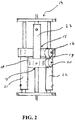
- Fig. 2 shows the drive unit, indicated in general with 14.
- Drive unit 14 comprises two gripping/moving systems that are arranged to alternatingly grip the rod and move it along its longitudinal axis over a predefined length and thus essentially are moving in opposite directions.
- the gripping/moving systems each comprise a gripper, which are not visible in fig. 2 but their respective positions are indicated by reference numerals 15 and 17.
- the first gripper 15 and second gripper 17 are each embedded in a gripper travel resp. 16 and 18.
- Opening and closing of each gripper is driven by a clamp cylinder, first gripper 15 is opened and closed by clamp cylinder 19 and the second gripper 17 is opened and closed by clamp cylinder 20.
- the two assemblies, each formed by a gripper 15, 17, a gripper travel 16, 18 and a clamp cylinder 19; 20 are each being moved up and down by two feed cylinders.
- the assembly comprising the first gripper 15 is moved by feed cylinders 21 and 22, whereas from the assembly comprising the second gripper 17, only one feed cylinder 23 is visible in fig. 2 .
- the two grippers 15, 17 alternatingly are making a 'work stroke' in the desired direction of movement of the rod and a 'return stroke'.
- Fig. 3 shows a geotechnical apparatus 1 with the unit 2 unit with coil holder and bending/straightening device and drive unit 14, as described above, being combined in a frame 7.
Landscapes
- Engineering & Computer Science (AREA)
- Life Sciences & Earth Sciences (AREA)
- Geology (AREA)
- Mining & Mineral Resources (AREA)
- Physics & Mathematics (AREA)
- General Life Sciences & Earth Sciences (AREA)
- Fluid Mechanics (AREA)
- Environmental & Geological Engineering (AREA)
- Mechanical Engineering (AREA)
- Geochemistry & Mineralogy (AREA)
- Analytical Chemistry (AREA)
- Chemical & Material Sciences (AREA)
- Health & Medical Sciences (AREA)
- Biochemistry (AREA)
- General Health & Medical Sciences (AREA)
- General Physics & Mathematics (AREA)
- Immunology (AREA)
- Pathology (AREA)
- Wire Processing (AREA)
Applications Claiming Priority (1)
| Application Number | Priority Date | Filing Date | Title |
|---|---|---|---|
| NL2017585A NL2017585B1 (en) | 2016-10-06 | 2016-10-06 | Geotechnical apparatus |
Publications (2)
| Publication Number | Publication Date |
|---|---|
| EP3306032A1 true EP3306032A1 (fr) | 2018-04-11 |
| EP3306032B1 EP3306032B1 (fr) | 2020-03-25 |
Family
ID=57460575
Family Applications (1)
| Application Number | Title | Priority Date | Filing Date |
|---|---|---|---|
| EP17194339.2A Active EP3306032B1 (fr) | 2016-10-06 | 2017-10-02 | Dispositif géotechnique |
Country Status (4)
| Country | Link |
|---|---|
| US (1) | US10527532B2 (fr) |
| EP (1) | EP3306032B1 (fr) |
| DK (1) | DK3306032T3 (fr) |
| NL (1) | NL2017585B1 (fr) |
Cited By (1)
| Publication number | Priority date | Publication date | Assignee | Title |
|---|---|---|---|---|
| WO2022167344A1 (fr) | 2021-02-02 | 2022-08-11 | Fnv Ip B.V. | Système de mesure souterrain commandé à distance |
Families Citing this family (2)
| Publication number | Priority date | Publication date | Assignee | Title |
|---|---|---|---|---|
| NL2015850B1 (en) | 2015-11-25 | 2017-06-13 | Fugro Eng B V | Geotechnical apparatus comprising at least one rod provided with a probe. |
| NL2031778B1 (en) * | 2022-05-04 | 2023-11-14 | Kormee B V | Directional drilling device |
Citations (7)
| Publication number | Priority date | Publication date | Assignee | Title |
|---|---|---|---|---|
| CA890228A (en) * | 1967-11-09 | 1972-01-11 | Palynchuk Alexander | Apparatus and method for running and pulling a continuous metal member into and out of a well |
| EP0803638A2 (fr) * | 1996-04-25 | 1997-10-29 | Halliburton Energy Services, Inc. | Méthode pour tester un tubage enroulé |
| US20030010505A1 (en) * | 2001-07-11 | 2003-01-16 | Coiled Tubing Solutions, Inc. | Oil well tubing injection system |
| US6527055B1 (en) * | 2001-09-28 | 2003-03-04 | Coiled Tubing Solutions, Inc. | Thrust enhancement device for coiled tubing injectors |
| US20050133228A1 (en) * | 2003-12-19 | 2005-06-23 | Shampine Rod W. | Tubular injector apparatus and method of use |
| US20110154908A1 (en) * | 2009-12-30 | 2011-06-30 | Mckee L Michael | Life monitor for a well access line |
| US20110289994A1 (en) * | 2010-05-27 | 2011-12-01 | Smith David P | System and method for straightening tubing |
Family Cites Families (6)
| Publication number | Priority date | Publication date | Assignee | Title |
|---|---|---|---|---|
| CA890288A (en) | 1972-01-11 | Esso Production Research Company | Drilling riser | |
| US3379052A (en) | 1965-09-20 | 1968-04-23 | Earle A. Howard | Soil penetrometer |
| US4499954A (en) | 1983-07-12 | 1985-02-19 | Diggle Dennis A | Geotechnical cone lubrication apparatus and method |
| US6923273B2 (en) * | 1997-10-27 | 2005-08-02 | Halliburton Energy Services, Inc. | Well system |
| DE69928666D1 (de) | 1998-06-22 | 2006-01-05 | Henry A Bernat Shreveport | Einführungsvorrichtung für rohrstrang mit oszillator |
| NL2015850B1 (en) * | 2015-11-25 | 2017-06-13 | Fugro Eng B V | Geotechnical apparatus comprising at least one rod provided with a probe. |
-
2016
- 2016-10-06 NL NL2017585A patent/NL2017585B1/nl not_active IP Right Cessation
-
2017
- 2017-10-02 EP EP17194339.2A patent/EP3306032B1/fr active Active
- 2017-10-02 DK DK17194339.2T patent/DK3306032T3/da active
- 2017-10-04 US US15/724,524 patent/US10527532B2/en active Active
Patent Citations (8)
| Publication number | Priority date | Publication date | Assignee | Title |
|---|---|---|---|---|
| CA890228A (en) * | 1967-11-09 | 1972-01-11 | Palynchuk Alexander | Apparatus and method for running and pulling a continuous metal member into and out of a well |
| EP0803638A2 (fr) * | 1996-04-25 | 1997-10-29 | Halliburton Energy Services, Inc. | Méthode pour tester un tubage enroulé |
| US20030010505A1 (en) * | 2001-07-11 | 2003-01-16 | Coiled Tubing Solutions, Inc. | Oil well tubing injection system |
| US6527055B1 (en) * | 2001-09-28 | 2003-03-04 | Coiled Tubing Solutions, Inc. | Thrust enhancement device for coiled tubing injectors |
| US20050133228A1 (en) * | 2003-12-19 | 2005-06-23 | Shampine Rod W. | Tubular injector apparatus and method of use |
| WO2005061842A1 (fr) * | 2003-12-19 | 2005-07-07 | Schlumberger Canada Limited | Appareil injecteur de tubulaires et son procede d'utilisation |
| US20110154908A1 (en) * | 2009-12-30 | 2011-06-30 | Mckee L Michael | Life monitor for a well access line |
| US20110289994A1 (en) * | 2010-05-27 | 2011-12-01 | Smith David P | System and method for straightening tubing |
Cited By (2)
| Publication number | Priority date | Publication date | Assignee | Title |
|---|---|---|---|---|
| WO2022167344A1 (fr) | 2021-02-02 | 2022-08-11 | Fnv Ip B.V. | Système de mesure souterrain commandé à distance |
| NL2027477B1 (en) | 2021-02-02 | 2022-09-05 | Fnv Ip Bv | System for remotely operated subsurface measurements |
Also Published As
| Publication number | Publication date |
|---|---|
| US10527532B2 (en) | 2020-01-07 |
| DK3306032T3 (da) | 2020-05-25 |
| NL2017585B1 (en) | 2018-04-13 |
| EP3306032B1 (fr) | 2020-03-25 |
| US20180156704A1 (en) | 2018-06-07 |
Similar Documents
| Publication | Publication Date | Title |
|---|---|---|
| EP3306032B1 (fr) | Dispositif géotechnique | |
| GB1419992A (en) | Electro-erosion machining | |
| US20100083721A1 (en) | Decoiler for wire and rod | |
| DE2141424A1 (de) | Ausfahrbare und einziehbare Auslegeranordnung | |
| CN104929545B (zh) | 铁钻工自动找中方法 | |
| US8414035B2 (en) | System and method for providing knot tying | |
| DE102009037515B4 (de) | Vorrichtung und Verfahren zum Führen von Versorgungsleitungen an einem Gelenkroboter | |
| EP3263243A1 (fr) | Dispositif de fabrication de ressort hélicoïdal et procédé de fabrication de ressort hélicoïdal | |
| DE102010004822A1 (de) | Rohrmanipulator | |
| US4462529A (en) | Linear accelerator system for axially advancing an elongate workpiece | |
| US10875739B2 (en) | Detachable line guide | |
| CN102502441A (zh) | 一种绞车排绳器 | |
| DE3612805C2 (de) | Verfahren und Vorrichtung zum Herstellen eines im Querschnitt hohlzylinderförmigen langgestreckten Gutes | |
| JPS62112899A (ja) | ワイヤ案内方法及び装置 | |
| JPH11314850A (ja) | リ―ルに巻回された材料のための力可変繰出し機構 | |
| EP3173531A1 (fr) | Apparatus pour l'investigation d'un sol | |
| CN109775595B (zh) | 一种多径缆自适应绞车导缆机构 | |
| US20200017339A1 (en) | Resealable Line Guide | |
| US3010568A (en) | Means for gripping rods | |
| JP5211709B2 (ja) | ワイヤ張力付与装置 | |
| DE1091645B (de) | Geraet zum Einschieben einer biegsamen Stahldrahtspirale fuer ein Einfuehren von Draehten in elektrische Leitungsrohre | |
| CN111313312B (zh) | 一种电力施工过程中线缆外皮保护装置及保护方法 | |
| CN118877647B (zh) | 一种电力施工牵引装置 | |
| EP0621437A1 (fr) | Tuyau de propulsion pour un dispositif d'inspection des tubes | |
| DE102004058330A1 (de) | Spuler |
Legal Events
| Date | Code | Title | Description |
|---|---|---|---|
| PUAI | Public reference made under article 153(3) epc to a published international application that has entered the european phase |
Free format text: ORIGINAL CODE: 0009012 |
|
| STAA | Information on the status of an ep patent application or granted ep patent |
Free format text: STATUS: THE APPLICATION HAS BEEN PUBLISHED |
|
| AK | Designated contracting states |
Kind code of ref document: A1 Designated state(s): AL AT BE BG CH CY CZ DE DK EE ES FI FR GB GR HR HU IE IS IT LI LT LU LV MC MK MT NL NO PL PT RO RS SE SI SK SM TR |
|
| AX | Request for extension of the european patent |
Extension state: BA ME |
|
| STAA | Information on the status of an ep patent application or granted ep patent |
Free format text: STATUS: REQUEST FOR EXAMINATION WAS MADE |
|
| 17P | Request for examination filed |
Effective date: 20180820 |
|
| RBV | Designated contracting states (corrected) |
Designated state(s): AL AT BE BG CH CY CZ DE DK EE ES FI FR GB GR HR HU IE IS IT LI LT LU LV MC MK MT NL NO PL PT RO RS SE SI SK SM TR |
|
| STAA | Information on the status of an ep patent application or granted ep patent |
Free format text: STATUS: EXAMINATION IS IN PROGRESS |
|
| 17Q | First examination report despatched |
Effective date: 20181218 |
|
| GRAP | Despatch of communication of intention to grant a patent |
Free format text: ORIGINAL CODE: EPIDOSNIGR1 |
|
| STAA | Information on the status of an ep patent application or granted ep patent |
Free format text: STATUS: GRANT OF PATENT IS INTENDED |
|
| INTG | Intention to grant announced |
Effective date: 20191211 |
|
| GRAS | Grant fee paid |
Free format text: ORIGINAL CODE: EPIDOSNIGR3 |
|
| GRAA | (expected) grant |
Free format text: ORIGINAL CODE: 0009210 |
|
| STAA | Information on the status of an ep patent application or granted ep patent |
Free format text: STATUS: THE PATENT HAS BEEN GRANTED |
|
| AK | Designated contracting states |
Kind code of ref document: B1 Designated state(s): AL AT BE BG CH CY CZ DE DK EE ES FI FR GB GR HR HU IE IS IT LI LT LU LV MC MK MT NL NO PL PT RO RS SE SI SK SM TR |
|
| REG | Reference to a national code |
Ref country code: GB Ref legal event code: FG4D |
|
| REG | Reference to a national code |
Ref country code: AT Ref legal event code: REF Ref document number: 1248774 Country of ref document: AT Kind code of ref document: T Effective date: 20200415 Ref country code: IE Ref legal event code: FG4D |
|
| REG | Reference to a national code |
Ref country code: DE Ref legal event code: R096 Ref document number: 602017013531 Country of ref document: DE |
|
| REG | Reference to a national code |
Ref country code: NL Ref legal event code: FP |
|
| REG | Reference to a national code |
Ref country code: DK Ref legal event code: T3 Effective date: 20200520 |
|
| PG25 | Lapsed in a contracting state [announced via postgrant information from national office to epo] |
Ref country code: RS Free format text: LAPSE BECAUSE OF FAILURE TO SUBMIT A TRANSLATION OF THE DESCRIPTION OR TO PAY THE FEE WITHIN THE PRESCRIBED TIME-LIMIT Effective date: 20200325 Ref country code: FI Free format text: LAPSE BECAUSE OF FAILURE TO SUBMIT A TRANSLATION OF THE DESCRIPTION OR TO PAY THE FEE WITHIN THE PRESCRIBED TIME-LIMIT Effective date: 20200325 |
|
| REG | Reference to a national code |
Ref country code: NO Ref legal event code: T2 Effective date: 20200325 |
|
| PG25 | Lapsed in a contracting state [announced via postgrant information from national office to epo] |
Ref country code: HR Free format text: LAPSE BECAUSE OF FAILURE TO SUBMIT A TRANSLATION OF THE DESCRIPTION OR TO PAY THE FEE WITHIN THE PRESCRIBED TIME-LIMIT Effective date: 20200325 Ref country code: BG Free format text: LAPSE BECAUSE OF FAILURE TO SUBMIT A TRANSLATION OF THE DESCRIPTION OR TO PAY THE FEE WITHIN THE PRESCRIBED TIME-LIMIT Effective date: 20200625 Ref country code: GR Free format text: LAPSE BECAUSE OF FAILURE TO SUBMIT A TRANSLATION OF THE DESCRIPTION OR TO PAY THE FEE WITHIN THE PRESCRIBED TIME-LIMIT Effective date: 20200626 Ref country code: SE Free format text: LAPSE BECAUSE OF FAILURE TO SUBMIT A TRANSLATION OF THE DESCRIPTION OR TO PAY THE FEE WITHIN THE PRESCRIBED TIME-LIMIT Effective date: 20200325 Ref country code: LV Free format text: LAPSE BECAUSE OF FAILURE TO SUBMIT A TRANSLATION OF THE DESCRIPTION OR TO PAY THE FEE WITHIN THE PRESCRIBED TIME-LIMIT Effective date: 20200325 |
|
| REG | Reference to a national code |
Ref country code: LT Ref legal event code: MG4D |
|
| PG25 | Lapsed in a contracting state [announced via postgrant information from national office to epo] |
Ref country code: CZ Free format text: LAPSE BECAUSE OF FAILURE TO SUBMIT A TRANSLATION OF THE DESCRIPTION OR TO PAY THE FEE WITHIN THE PRESCRIBED TIME-LIMIT Effective date: 20200325 Ref country code: SK Free format text: LAPSE BECAUSE OF FAILURE TO SUBMIT A TRANSLATION OF THE DESCRIPTION OR TO PAY THE FEE WITHIN THE PRESCRIBED TIME-LIMIT Effective date: 20200325 Ref country code: RO Free format text: LAPSE BECAUSE OF FAILURE TO SUBMIT A TRANSLATION OF THE DESCRIPTION OR TO PAY THE FEE WITHIN THE PRESCRIBED TIME-LIMIT Effective date: 20200325 Ref country code: IS Free format text: LAPSE BECAUSE OF FAILURE TO SUBMIT A TRANSLATION OF THE DESCRIPTION OR TO PAY THE FEE WITHIN THE PRESCRIBED TIME-LIMIT Effective date: 20200725 Ref country code: SM Free format text: LAPSE BECAUSE OF FAILURE TO SUBMIT A TRANSLATION OF THE DESCRIPTION OR TO PAY THE FEE WITHIN THE PRESCRIBED TIME-LIMIT Effective date: 20200325 Ref country code: EE Free format text: LAPSE BECAUSE OF FAILURE TO SUBMIT A TRANSLATION OF THE DESCRIPTION OR TO PAY THE FEE WITHIN THE PRESCRIBED TIME-LIMIT Effective date: 20200325 Ref country code: PT Free format text: LAPSE BECAUSE OF FAILURE TO SUBMIT A TRANSLATION OF THE DESCRIPTION OR TO PAY THE FEE WITHIN THE PRESCRIBED TIME-LIMIT Effective date: 20200818 Ref country code: LT Free format text: LAPSE BECAUSE OF FAILURE TO SUBMIT A TRANSLATION OF THE DESCRIPTION OR TO PAY THE FEE WITHIN THE PRESCRIBED TIME-LIMIT Effective date: 20200325 |
|
| REG | Reference to a national code |
Ref country code: AT Ref legal event code: MK05 Ref document number: 1248774 Country of ref document: AT Kind code of ref document: T Effective date: 20200325 |
|
| REG | Reference to a national code |
Ref country code: NL Ref legal event code: HC Owner name: FUGRO NETHERLANDS MARINE B.V.; NL Free format text: DETAILS ASSIGNMENT: CHANGE OF OWNER(S), CHANGE OF OWNER(S) NAME; FORMER OWNER NAME: FUGRO ENGINEERS B.V. Effective date: 20201221 Ref country code: NL Ref legal event code: RC Free format text: DETAILS LICENCE OR PLEDGE: RIGHT OF PLEDGE, ESTABLISHED Name of requester: COOEPERATIEVE RABOBANK U.A. Effective date: 20201221 |
|
| REG | Reference to a national code |
Ref country code: DE Ref legal event code: R097 Ref document number: 602017013531 Country of ref document: DE |
|
| PG25 | Lapsed in a contracting state [announced via postgrant information from national office to epo] |
Ref country code: AT Free format text: LAPSE BECAUSE OF FAILURE TO SUBMIT A TRANSLATION OF THE DESCRIPTION OR TO PAY THE FEE WITHIN THE PRESCRIBED TIME-LIMIT Effective date: 20200325 Ref country code: ES Free format text: LAPSE BECAUSE OF FAILURE TO SUBMIT A TRANSLATION OF THE DESCRIPTION OR TO PAY THE FEE WITHIN THE PRESCRIBED TIME-LIMIT Effective date: 20200325 Ref country code: IT Free format text: LAPSE BECAUSE OF FAILURE TO SUBMIT A TRANSLATION OF THE DESCRIPTION OR TO PAY THE FEE WITHIN THE PRESCRIBED TIME-LIMIT Effective date: 20200325 |
|
| REG | Reference to a national code |
Ref country code: NL Ref legal event code: RC Free format text: DETAILS LICENCE OR PLEDGE: RIGHT OF PLEDGE, ESTABLISHED Name of requester: COOEPERATIEVE RABOBANK U.A. Effective date: 20210118 |
|
| PLBE | No opposition filed within time limit |
Free format text: ORIGINAL CODE: 0009261 |
|
| STAA | Information on the status of an ep patent application or granted ep patent |
Free format text: STATUS: NO OPPOSITION FILED WITHIN TIME LIMIT |
|
| PG25 | Lapsed in a contracting state [announced via postgrant information from national office to epo] |
Ref country code: PL Free format text: LAPSE BECAUSE OF FAILURE TO SUBMIT A TRANSLATION OF THE DESCRIPTION OR TO PAY THE FEE WITHIN THE PRESCRIBED TIME-LIMIT Effective date: 20200325 |
|
| 26N | No opposition filed |
Effective date: 20210112 |
|
| PG25 | Lapsed in a contracting state [announced via postgrant information from national office to epo] |
Ref country code: SI Free format text: LAPSE BECAUSE OF FAILURE TO SUBMIT A TRANSLATION OF THE DESCRIPTION OR TO PAY THE FEE WITHIN THE PRESCRIBED TIME-LIMIT Effective date: 20200325 |
|
| REG | Reference to a national code |
Ref country code: CH Ref legal event code: PL |
|
| PG25 | Lapsed in a contracting state [announced via postgrant information from national office to epo] |
Ref country code: LU Free format text: LAPSE BECAUSE OF NON-PAYMENT OF DUE FEES Effective date: 20201002 Ref country code: MC Free format text: LAPSE BECAUSE OF FAILURE TO SUBMIT A TRANSLATION OF THE DESCRIPTION OR TO PAY THE FEE WITHIN THE PRESCRIBED TIME-LIMIT Effective date: 20200325 |
|
| REG | Reference to a national code |
Ref country code: BE Ref legal event code: MM Effective date: 20201031 |
|
| PG25 | Lapsed in a contracting state [announced via postgrant information from national office to epo] |
Ref country code: FR Free format text: LAPSE BECAUSE OF NON-PAYMENT OF DUE FEES Effective date: 20201031 |
|
| PG25 | Lapsed in a contracting state [announced via postgrant information from national office to epo] |
Ref country code: LI Free format text: LAPSE BECAUSE OF NON-PAYMENT OF DUE FEES Effective date: 20201031 Ref country code: BE Free format text: LAPSE BECAUSE OF NON-PAYMENT OF DUE FEES Effective date: 20201031 Ref country code: CH Free format text: LAPSE BECAUSE OF NON-PAYMENT OF DUE FEES Effective date: 20201031 |
|
| PG25 | Lapsed in a contracting state [announced via postgrant information from national office to epo] |
Ref country code: IE Free format text: LAPSE BECAUSE OF NON-PAYMENT OF DUE FEES Effective date: 20201002 |
|
| PG25 | Lapsed in a contracting state [announced via postgrant information from national office to epo] |
Ref country code: TR Free format text: LAPSE BECAUSE OF FAILURE TO SUBMIT A TRANSLATION OF THE DESCRIPTION OR TO PAY THE FEE WITHIN THE PRESCRIBED TIME-LIMIT Effective date: 20200325 Ref country code: MT Free format text: LAPSE BECAUSE OF FAILURE TO SUBMIT A TRANSLATION OF THE DESCRIPTION OR TO PAY THE FEE WITHIN THE PRESCRIBED TIME-LIMIT Effective date: 20200325 Ref country code: CY Free format text: LAPSE BECAUSE OF FAILURE TO SUBMIT A TRANSLATION OF THE DESCRIPTION OR TO PAY THE FEE WITHIN THE PRESCRIBED TIME-LIMIT Effective date: 20200325 |
|
| PG25 | Lapsed in a contracting state [announced via postgrant information from national office to epo] |
Ref country code: MK Free format text: LAPSE BECAUSE OF FAILURE TO SUBMIT A TRANSLATION OF THE DESCRIPTION OR TO PAY THE FEE WITHIN THE PRESCRIBED TIME-LIMIT Effective date: 20200325 Ref country code: AL Free format text: LAPSE BECAUSE OF FAILURE TO SUBMIT A TRANSLATION OF THE DESCRIPTION OR TO PAY THE FEE WITHIN THE PRESCRIBED TIME-LIMIT Effective date: 20200325 |
|
| P01 | Opt-out of the competence of the unified patent court (upc) registered |
Effective date: 20230519 |
|
| PGFP | Annual fee paid to national office [announced via postgrant information from national office to epo] |
Ref country code: NL Payment date: 20251023 Year of fee payment: 9 |
|
| PGFP | Annual fee paid to national office [announced via postgrant information from national office to epo] |
Ref country code: DE Payment date: 20251020 Year of fee payment: 9 |
|
| PGFP | Annual fee paid to national office [announced via postgrant information from national office to epo] |
Ref country code: GB Payment date: 20251024 Year of fee payment: 9 |
|
| PGFP | Annual fee paid to national office [announced via postgrant information from national office to epo] |
Ref country code: NO Payment date: 20251022 Year of fee payment: 9 |
|
| PGFP | Annual fee paid to national office [announced via postgrant information from national office to epo] |
Ref country code: DK Payment date: 20251023 Year of fee payment: 9 |