EP3306174A1 - Contenant de gaz haute pression - Google Patents
Contenant de gaz haute pression Download PDFInfo
- Publication number
- EP3306174A1 EP3306174A1 EP15893299.6A EP15893299A EP3306174A1 EP 3306174 A1 EP3306174 A1 EP 3306174A1 EP 15893299 A EP15893299 A EP 15893299A EP 3306174 A1 EP3306174 A1 EP 3306174A1
- Authority
- EP
- European Patent Office
- Prior art keywords
- gas
- inner layer
- outer layer
- pressure gas
- gas container
- Prior art date
- Legal status (The legal status is an assumption and is not a legal conclusion. Google has not performed a legal analysis and makes no representation as to the accuracy of the status listed.)
- Granted
Links
- 238000009423 ventilation Methods 0.000 claims abstract description 92
- 239000000463 material Substances 0.000 claims description 55
- 238000004804 winding Methods 0.000 claims description 47
- 239000002657 fibrous material Substances 0.000 claims description 38
- 229920005989 resin Polymers 0.000 claims description 35
- 239000011347 resin Substances 0.000 claims description 35
- 239000005871 repellent Substances 0.000 claims description 12
- 239000012510 hollow fiber Substances 0.000 claims description 11
- 239000012528 membrane Substances 0.000 claims description 11
- 230000035699 permeability Effects 0.000 claims description 11
- 239000007788 liquid Substances 0.000 claims description 9
- 230000004888 barrier function Effects 0.000 abstract description 5
- 239000007789 gas Substances 0.000 description 218
- 229920000049 Carbon (fiber) Polymers 0.000 description 36
- 239000004917 carbon fiber Substances 0.000 description 36
- VNWKTOKETHGBQD-UHFFFAOYSA-N methane Chemical compound C VNWKTOKETHGBQD-UHFFFAOYSA-N 0.000 description 36
- 230000002093 peripheral effect Effects 0.000 description 33
- 238000010586 diagram Methods 0.000 description 12
- 230000000694 effects Effects 0.000 description 10
- 230000003014 reinforcing effect Effects 0.000 description 10
- 238000000034 method Methods 0.000 description 8
- 239000000446 fuel Substances 0.000 description 6
- 238000004519 manufacturing process Methods 0.000 description 6
- UFHFLCQGNIYNRP-UHFFFAOYSA-N Hydrogen Chemical compound [H][H] UFHFLCQGNIYNRP-UHFFFAOYSA-N 0.000 description 5
- 238000007599 discharging Methods 0.000 description 4
- 125000006850 spacer group Chemical group 0.000 description 4
- 230000001771 impaired effect Effects 0.000 description 3
- 230000035515 penetration Effects 0.000 description 3
- -1 polypropylene Polymers 0.000 description 3
- 229920001343 polytetrafluoroethylene Polymers 0.000 description 3
- 239000004810 polytetrafluoroethylene Substances 0.000 description 3
- 230000008569 process Effects 0.000 description 3
- 230000009467 reduction Effects 0.000 description 3
- XLYOFNOQVPJJNP-UHFFFAOYSA-N water Substances O XLYOFNOQVPJJNP-UHFFFAOYSA-N 0.000 description 3
- 230000000903 blocking effect Effects 0.000 description 2
- 239000004918 carbon fiber reinforced polymer Substances 0.000 description 2
- 239000003822 epoxy resin Substances 0.000 description 2
- 239000002737 fuel gas Substances 0.000 description 2
- 229910052739 hydrogen Inorganic materials 0.000 description 2
- 239000001257 hydrogen Substances 0.000 description 2
- 229920000647 polyepoxide Polymers 0.000 description 2
- 229920002635 polyurethane Polymers 0.000 description 2
- 239000004814 polyurethane Substances 0.000 description 2
- 230000002940 repellent Effects 0.000 description 2
- 230000007704 transition Effects 0.000 description 2
- 229920000544 Gore-Tex Polymers 0.000 description 1
- 239000004698 Polyethylene Substances 0.000 description 1
- 239000004743 Polypropylene Substances 0.000 description 1
- 230000009471 action Effects 0.000 description 1
- 229910052782 aluminium Inorganic materials 0.000 description 1
- XAGFODPZIPBFFR-UHFFFAOYSA-N aluminium Chemical compound [Al] XAGFODPZIPBFFR-UHFFFAOYSA-N 0.000 description 1
- 230000015572 biosynthetic process Effects 0.000 description 1
- 238000000071 blow moulding Methods 0.000 description 1
- 238000013329 compounding Methods 0.000 description 1
- 230000005494 condensation Effects 0.000 description 1
- 238000009833 condensation Methods 0.000 description 1
- 230000032798 delamination Effects 0.000 description 1
- 238000009730 filament winding Methods 0.000 description 1
- 238000005470 impregnation Methods 0.000 description 1
- 239000007769 metal material Substances 0.000 description 1
- 238000000465 moulding Methods 0.000 description 1
- 230000000149 penetrating effect Effects 0.000 description 1
- 239000012466 permeate Substances 0.000 description 1
- 229920000573 polyethylene Polymers 0.000 description 1
- 229920013716 polyethylene resin Polymers 0.000 description 1
- 229920000642 polymer Polymers 0.000 description 1
- 229920005597 polymer membrane Polymers 0.000 description 1
- 229920001155 polypropylene Polymers 0.000 description 1
- 239000011148 porous material Substances 0.000 description 1
- 230000002787 reinforcement Effects 0.000 description 1
- 229910001220 stainless steel Inorganic materials 0.000 description 1
- 239000010935 stainless steel Substances 0.000 description 1
Images




Classifications
-
- F—MECHANICAL ENGINEERING; LIGHTING; HEATING; WEAPONS; BLASTING
- F17—STORING OR DISTRIBUTING GASES OR LIQUIDS
- F17C—VESSELS FOR CONTAINING OR STORING COMPRESSED, LIQUEFIED OR SOLIDIFIED GASES; FIXED-CAPACITY GAS-HOLDERS; FILLING VESSELS WITH, OR DISCHARGING FROM VESSELS, COMPRESSED, LIQUEFIED, OR SOLIDIFIED GASES
- F17C1/00—Pressure vessels, e.g. gas cylinder, gas tank, replaceable cartridge
- F17C1/02—Pressure vessels, e.g. gas cylinder, gas tank, replaceable cartridge involving reinforcing arrangements
- F17C1/04—Protecting sheathings
- F17C1/06—Protecting sheathings built-up from wound-on bands or filamentary material, e.g. wires
-
- F—MECHANICAL ENGINEERING; LIGHTING; HEATING; WEAPONS; BLASTING
- F17—STORING OR DISTRIBUTING GASES OR LIQUIDS
- F17C—VESSELS FOR CONTAINING OR STORING COMPRESSED, LIQUEFIED OR SOLIDIFIED GASES; FIXED-CAPACITY GAS-HOLDERS; FILLING VESSELS WITH, OR DISCHARGING FROM VESSELS, COMPRESSED, LIQUEFIED, OR SOLIDIFIED GASES
- F17C13/00—Details of vessels or of the filling or discharging of vessels
-
- F—MECHANICAL ENGINEERING; LIGHTING; HEATING; WEAPONS; BLASTING
- F17—STORING OR DISTRIBUTING GASES OR LIQUIDS
- F17C—VESSELS FOR CONTAINING OR STORING COMPRESSED, LIQUEFIED OR SOLIDIFIED GASES; FIXED-CAPACITY GAS-HOLDERS; FILLING VESSELS WITH, OR DISCHARGING FROM VESSELS, COMPRESSED, LIQUEFIED, OR SOLIDIFIED GASES
- F17C1/00—Pressure vessels, e.g. gas cylinder, gas tank, replaceable cartridge
- F17C1/16—Pressure vessels, e.g. gas cylinder, gas tank, replaceable cartridge constructed of plastics materials
-
- F—MECHANICAL ENGINEERING; LIGHTING; HEATING; WEAPONS; BLASTING
- F17—STORING OR DISTRIBUTING GASES OR LIQUIDS
- F17C—VESSELS FOR CONTAINING OR STORING COMPRESSED, LIQUEFIED OR SOLIDIFIED GASES; FIXED-CAPACITY GAS-HOLDERS; FILLING VESSELS WITH, OR DISCHARGING FROM VESSELS, COMPRESSED, LIQUEFIED, OR SOLIDIFIED GASES
- F17C2201/00—Vessel construction, in particular geometry, arrangement or size
- F17C2201/01—Shape
- F17C2201/0104—Shape cylindrical
- F17C2201/0109—Shape cylindrical with exteriorly curved end-piece
-
- F—MECHANICAL ENGINEERING; LIGHTING; HEATING; WEAPONS; BLASTING
- F17—STORING OR DISTRIBUTING GASES OR LIQUIDS
- F17C—VESSELS FOR CONTAINING OR STORING COMPRESSED, LIQUEFIED OR SOLIDIFIED GASES; FIXED-CAPACITY GAS-HOLDERS; FILLING VESSELS WITH, OR DISCHARGING FROM VESSELS, COMPRESSED, LIQUEFIED, OR SOLIDIFIED GASES
- F17C2201/00—Vessel construction, in particular geometry, arrangement or size
- F17C2201/05—Size
- F17C2201/054—Size medium (>1 m3)
-
- F—MECHANICAL ENGINEERING; LIGHTING; HEATING; WEAPONS; BLASTING
- F17—STORING OR DISTRIBUTING GASES OR LIQUIDS
- F17C—VESSELS FOR CONTAINING OR STORING COMPRESSED, LIQUEFIED OR SOLIDIFIED GASES; FIXED-CAPACITY GAS-HOLDERS; FILLING VESSELS WITH, OR DISCHARGING FROM VESSELS, COMPRESSED, LIQUEFIED, OR SOLIDIFIED GASES
- F17C2203/00—Vessel construction, in particular walls or details thereof
- F17C2203/01—Reinforcing or suspension means
- F17C2203/011—Reinforcing means
- F17C2203/012—Reinforcing means on or in the wall, e.g. ribs
-
- F—MECHANICAL ENGINEERING; LIGHTING; HEATING; WEAPONS; BLASTING
- F17—STORING OR DISTRIBUTING GASES OR LIQUIDS
- F17C—VESSELS FOR CONTAINING OR STORING COMPRESSED, LIQUEFIED OR SOLIDIFIED GASES; FIXED-CAPACITY GAS-HOLDERS; FILLING VESSELS WITH, OR DISCHARGING FROM VESSELS, COMPRESSED, LIQUEFIED, OR SOLIDIFIED GASES
- F17C2203/00—Vessel construction, in particular walls or details thereof
- F17C2203/01—Reinforcing or suspension means
- F17C2203/014—Suspension means
-
- F—MECHANICAL ENGINEERING; LIGHTING; HEATING; WEAPONS; BLASTING
- F17—STORING OR DISTRIBUTING GASES OR LIQUIDS
- F17C—VESSELS FOR CONTAINING OR STORING COMPRESSED, LIQUEFIED OR SOLIDIFIED GASES; FIXED-CAPACITY GAS-HOLDERS; FILLING VESSELS WITH, OR DISCHARGING FROM VESSELS, COMPRESSED, LIQUEFIED, OR SOLIDIFIED GASES
- F17C2203/00—Vessel construction, in particular walls or details thereof
- F17C2203/06—Materials for walls or layers thereof; Properties or structures of walls or their materials
- F17C2203/0602—Wall structures; Special features thereof
- F17C2203/0604—Liners
-
- F—MECHANICAL ENGINEERING; LIGHTING; HEATING; WEAPONS; BLASTING
- F17—STORING OR DISTRIBUTING GASES OR LIQUIDS
- F17C—VESSELS FOR CONTAINING OR STORING COMPRESSED, LIQUEFIED OR SOLIDIFIED GASES; FIXED-CAPACITY GAS-HOLDERS; FILLING VESSELS WITH, OR DISCHARGING FROM VESSELS, COMPRESSED, LIQUEFIED, OR SOLIDIFIED GASES
- F17C2203/00—Vessel construction, in particular walls or details thereof
- F17C2203/06—Materials for walls or layers thereof; Properties or structures of walls or their materials
- F17C2203/0602—Wall structures; Special features thereof
- F17C2203/0612—Wall structures
- F17C2203/0614—Single wall
- F17C2203/0621—Single wall with three layers
-
- F—MECHANICAL ENGINEERING; LIGHTING; HEATING; WEAPONS; BLASTING
- F17—STORING OR DISTRIBUTING GASES OR LIQUIDS
- F17C—VESSELS FOR CONTAINING OR STORING COMPRESSED, LIQUEFIED OR SOLIDIFIED GASES; FIXED-CAPACITY GAS-HOLDERS; FILLING VESSELS WITH, OR DISCHARGING FROM VESSELS, COMPRESSED, LIQUEFIED, OR SOLIDIFIED GASES
- F17C2203/00—Vessel construction, in particular walls or details thereof
- F17C2203/06—Materials for walls or layers thereof; Properties or structures of walls or their materials
- F17C2203/0602—Wall structures; Special features thereof
- F17C2203/0612—Wall structures
- F17C2203/0626—Multiple walls
- F17C2203/0629—Two walls
-
- F—MECHANICAL ENGINEERING; LIGHTING; HEATING; WEAPONS; BLASTING
- F17—STORING OR DISTRIBUTING GASES OR LIQUIDS
- F17C—VESSELS FOR CONTAINING OR STORING COMPRESSED, LIQUEFIED OR SOLIDIFIED GASES; FIXED-CAPACITY GAS-HOLDERS; FILLING VESSELS WITH, OR DISCHARGING FROM VESSELS, COMPRESSED, LIQUEFIED, OR SOLIDIFIED GASES
- F17C2203/00—Vessel construction, in particular walls or details thereof
- F17C2203/06—Materials for walls or layers thereof; Properties or structures of walls or their materials
- F17C2203/0634—Materials for walls or layers thereof
- F17C2203/0658—Synthetics
- F17C2203/0663—Synthetics in form of fibers or filaments
- F17C2203/067—Synthetics in form of fibers or filaments helically wound
-
- F—MECHANICAL ENGINEERING; LIGHTING; HEATING; WEAPONS; BLASTING
- F17—STORING OR DISTRIBUTING GASES OR LIQUIDS
- F17C—VESSELS FOR CONTAINING OR STORING COMPRESSED, LIQUEFIED OR SOLIDIFIED GASES; FIXED-CAPACITY GAS-HOLDERS; FILLING VESSELS WITH, OR DISCHARGING FROM VESSELS, COMPRESSED, LIQUEFIED, OR SOLIDIFIED GASES
- F17C2203/00—Vessel construction, in particular walls or details thereof
- F17C2203/06—Materials for walls or layers thereof; Properties or structures of walls or their materials
- F17C2203/068—Special properties of materials for vessel walls
- F17C2203/0682—Special properties of materials for vessel walls with liquid or gas layer
-
- F—MECHANICAL ENGINEERING; LIGHTING; HEATING; WEAPONS; BLASTING
- F17—STORING OR DISTRIBUTING GASES OR LIQUIDS
- F17C—VESSELS FOR CONTAINING OR STORING COMPRESSED, LIQUEFIED OR SOLIDIFIED GASES; FIXED-CAPACITY GAS-HOLDERS; FILLING VESSELS WITH, OR DISCHARGING FROM VESSELS, COMPRESSED, LIQUEFIED, OR SOLIDIFIED GASES
- F17C2205/00—Vessel construction, in particular mounting arrangements, attachments or identifications means
- F17C2205/03—Fluid connections, filters, valves, closure means or other attachments
- F17C2205/0302—Fittings, valves, filters, or components in connection with the gas storage device
- F17C2205/0305—Bosses, e.g. boss collars
-
- F—MECHANICAL ENGINEERING; LIGHTING; HEATING; WEAPONS; BLASTING
- F17—STORING OR DISTRIBUTING GASES OR LIQUIDS
- F17C—VESSELS FOR CONTAINING OR STORING COMPRESSED, LIQUEFIED OR SOLIDIFIED GASES; FIXED-CAPACITY GAS-HOLDERS; FILLING VESSELS WITH, OR DISCHARGING FROM VESSELS, COMPRESSED, LIQUEFIED, OR SOLIDIFIED GASES
- F17C2205/00—Vessel construction, in particular mounting arrangements, attachments or identifications means
- F17C2205/03—Fluid connections, filters, valves, closure means or other attachments
- F17C2205/0302—Fittings, valves, filters, or components in connection with the gas storage device
- F17C2205/0311—Closure means
- F17C2205/0317—Closure means fusing or melting
-
- F—MECHANICAL ENGINEERING; LIGHTING; HEATING; WEAPONS; BLASTING
- F17—STORING OR DISTRIBUTING GASES OR LIQUIDS
- F17C—VESSELS FOR CONTAINING OR STORING COMPRESSED, LIQUEFIED OR SOLIDIFIED GASES; FIXED-CAPACITY GAS-HOLDERS; FILLING VESSELS WITH, OR DISCHARGING FROM VESSELS, COMPRESSED, LIQUEFIED, OR SOLIDIFIED GASES
- F17C2205/00—Vessel construction, in particular mounting arrangements, attachments or identifications means
- F17C2205/03—Fluid connections, filters, valves, closure means or other attachments
- F17C2205/0302—Fittings, valves, filters, or components in connection with the gas storage device
- F17C2205/0323—Valves
-
- F—MECHANICAL ENGINEERING; LIGHTING; HEATING; WEAPONS; BLASTING
- F17—STORING OR DISTRIBUTING GASES OR LIQUIDS
- F17C—VESSELS FOR CONTAINING OR STORING COMPRESSED, LIQUEFIED OR SOLIDIFIED GASES; FIXED-CAPACITY GAS-HOLDERS; FILLING VESSELS WITH, OR DISCHARGING FROM VESSELS, COMPRESSED, LIQUEFIED, OR SOLIDIFIED GASES
- F17C2209/00—Vessel construction, in particular methods of manufacturing
- F17C2209/21—Shaping processes
- F17C2209/2109—Moulding
-
- F—MECHANICAL ENGINEERING; LIGHTING; HEATING; WEAPONS; BLASTING
- F17—STORING OR DISTRIBUTING GASES OR LIQUIDS
- F17C—VESSELS FOR CONTAINING OR STORING COMPRESSED, LIQUEFIED OR SOLIDIFIED GASES; FIXED-CAPACITY GAS-HOLDERS; FILLING VESSELS WITH, OR DISCHARGING FROM VESSELS, COMPRESSED, LIQUEFIED, OR SOLIDIFIED GASES
- F17C2209/00—Vessel construction, in particular methods of manufacturing
- F17C2209/21—Shaping processes
- F17C2209/2109—Moulding
- F17C2209/2127—Moulding by blowing
-
- F—MECHANICAL ENGINEERING; LIGHTING; HEATING; WEAPONS; BLASTING
- F17—STORING OR DISTRIBUTING GASES OR LIQUIDS
- F17C—VESSELS FOR CONTAINING OR STORING COMPRESSED, LIQUEFIED OR SOLIDIFIED GASES; FIXED-CAPACITY GAS-HOLDERS; FILLING VESSELS WITH, OR DISCHARGING FROM VESSELS, COMPRESSED, LIQUEFIED, OR SOLIDIFIED GASES
- F17C2209/00—Vessel construction, in particular methods of manufacturing
- F17C2209/21—Shaping processes
- F17C2209/2154—Winding
-
- F—MECHANICAL ENGINEERING; LIGHTING; HEATING; WEAPONS; BLASTING
- F17—STORING OR DISTRIBUTING GASES OR LIQUIDS
- F17C—VESSELS FOR CONTAINING OR STORING COMPRESSED, LIQUEFIED OR SOLIDIFIED GASES; FIXED-CAPACITY GAS-HOLDERS; FILLING VESSELS WITH, OR DISCHARGING FROM VESSELS, COMPRESSED, LIQUEFIED, OR SOLIDIFIED GASES
- F17C2209/00—Vessel construction, in particular methods of manufacturing
- F17C2209/23—Manufacturing of particular parts or at special locations
- F17C2209/232—Manufacturing of particular parts or at special locations of walls
-
- F—MECHANICAL ENGINEERING; LIGHTING; HEATING; WEAPONS; BLASTING
- F17—STORING OR DISTRIBUTING GASES OR LIQUIDS
- F17C—VESSELS FOR CONTAINING OR STORING COMPRESSED, LIQUEFIED OR SOLIDIFIED GASES; FIXED-CAPACITY GAS-HOLDERS; FILLING VESSELS WITH, OR DISCHARGING FROM VESSELS, COMPRESSED, LIQUEFIED, OR SOLIDIFIED GASES
- F17C2209/00—Vessel construction, in particular methods of manufacturing
- F17C2209/23—Manufacturing of particular parts or at special locations
- F17C2209/234—Manufacturing of particular parts or at special locations of closing end pieces, e.g. caps
-
- F—MECHANICAL ENGINEERING; LIGHTING; HEATING; WEAPONS; BLASTING
- F17—STORING OR DISTRIBUTING GASES OR LIQUIDS
- F17C—VESSELS FOR CONTAINING OR STORING COMPRESSED, LIQUEFIED OR SOLIDIFIED GASES; FIXED-CAPACITY GAS-HOLDERS; FILLING VESSELS WITH, OR DISCHARGING FROM VESSELS, COMPRESSED, LIQUEFIED, OR SOLIDIFIED GASES
- F17C2221/00—Handled fluid, in particular type of fluid
- F17C2221/01—Pure fluids
- F17C2221/012—Hydrogen
-
- F—MECHANICAL ENGINEERING; LIGHTING; HEATING; WEAPONS; BLASTING
- F17—STORING OR DISTRIBUTING GASES OR LIQUIDS
- F17C—VESSELS FOR CONTAINING OR STORING COMPRESSED, LIQUEFIED OR SOLIDIFIED GASES; FIXED-CAPACITY GAS-HOLDERS; FILLING VESSELS WITH, OR DISCHARGING FROM VESSELS, COMPRESSED, LIQUEFIED, OR SOLIDIFIED GASES
- F17C2223/00—Handled fluid before transfer, i.e. state of fluid when stored in the vessel or before transfer from the vessel
- F17C2223/01—Handled fluid before transfer, i.e. state of fluid when stored in the vessel or before transfer from the vessel characterised by the phase
- F17C2223/0107—Single phase
- F17C2223/0123—Single phase gaseous, e.g. CNG, GNC
-
- F—MECHANICAL ENGINEERING; LIGHTING; HEATING; WEAPONS; BLASTING
- F17—STORING OR DISTRIBUTING GASES OR LIQUIDS
- F17C—VESSELS FOR CONTAINING OR STORING COMPRESSED, LIQUEFIED OR SOLIDIFIED GASES; FIXED-CAPACITY GAS-HOLDERS; FILLING VESSELS WITH, OR DISCHARGING FROM VESSELS, COMPRESSED, LIQUEFIED, OR SOLIDIFIED GASES
- F17C2223/00—Handled fluid before transfer, i.e. state of fluid when stored in the vessel or before transfer from the vessel
- F17C2223/03—Handled fluid before transfer, i.e. state of fluid when stored in the vessel or before transfer from the vessel characterised by the pressure level
- F17C2223/036—Very high pressure (>80 bar)
-
- F—MECHANICAL ENGINEERING; LIGHTING; HEATING; WEAPONS; BLASTING
- F17—STORING OR DISTRIBUTING GASES OR LIQUIDS
- F17C—VESSELS FOR CONTAINING OR STORING COMPRESSED, LIQUEFIED OR SOLIDIFIED GASES; FIXED-CAPACITY GAS-HOLDERS; FILLING VESSELS WITH, OR DISCHARGING FROM VESSELS, COMPRESSED, LIQUEFIED, OR SOLIDIFIED GASES
- F17C2260/00—Purposes of gas storage and gas handling
- F17C2260/03—Dealing with losses
- F17C2260/035—Dealing with losses of fluid
- F17C2260/037—Handling leaked fluid
-
- F—MECHANICAL ENGINEERING; LIGHTING; HEATING; WEAPONS; BLASTING
- F17—STORING OR DISTRIBUTING GASES OR LIQUIDS
- F17C—VESSELS FOR CONTAINING OR STORING COMPRESSED, LIQUEFIED OR SOLIDIFIED GASES; FIXED-CAPACITY GAS-HOLDERS; FILLING VESSELS WITH, OR DISCHARGING FROM VESSELS, COMPRESSED, LIQUEFIED, OR SOLIDIFIED GASES
- F17C2270/00—Applications
- F17C2270/01—Applications for fluid transport or storage
- F17C2270/0165—Applications for fluid transport or storage on the road
- F17C2270/0168—Applications for fluid transport or storage on the road by vehicles
-
- F—MECHANICAL ENGINEERING; LIGHTING; HEATING; WEAPONS; BLASTING
- F17—STORING OR DISTRIBUTING GASES OR LIQUIDS
- F17C—VESSELS FOR CONTAINING OR STORING COMPRESSED, LIQUEFIED OR SOLIDIFIED GASES; FIXED-CAPACITY GAS-HOLDERS; FILLING VESSELS WITH, OR DISCHARGING FROM VESSELS, COMPRESSED, LIQUEFIED, OR SOLIDIFIED GASES
- F17C2270/00—Applications
- F17C2270/01—Applications for fluid transport or storage
- F17C2270/0165—Applications for fluid transport or storage on the road
- F17C2270/0184—Fuel cells
-
- Y—GENERAL TAGGING OF NEW TECHNOLOGICAL DEVELOPMENTS; GENERAL TAGGING OF CROSS-SECTIONAL TECHNOLOGIES SPANNING OVER SEVERAL SECTIONS OF THE IPC; TECHNICAL SUBJECTS COVERED BY FORMER USPC CROSS-REFERENCE ART COLLECTIONS [XRACs] AND DIGESTS
- Y02—TECHNOLOGIES OR APPLICATIONS FOR MITIGATION OR ADAPTATION AGAINST CLIMATE CHANGE
- Y02E—REDUCTION OF GREENHOUSE GAS [GHG] EMISSIONS, RELATED TO ENERGY GENERATION, TRANSMISSION OR DISTRIBUTION
- Y02E60/00—Enabling technologies; Technologies with a potential or indirect contribution to GHG emissions mitigation
- Y02E60/30—Hydrogen technology
- Y02E60/32—Hydrogen storage
Definitions
- the present invention relates to a high-pressure gas container with an inner layer configured such that high-pressure gas is filled inside, a boss part provided at least at one position of the inner layer and configured to cause the gas to flow in and out, and a highly permeable outer layer configured to cover the outer periphery of the inner layer to reinforce the inner layer.
- a high-pressure gas container which is for storing gas such as hydrogen in a high-pressure state and formed by winding an outer layer formed of carbon fiber on an inner layer liner formed of resin or the like for reinforcement or the like.
- a hollow boss part configured to cause the gas to flow in and out is formed on one end or each of both ends of this high-pressure gas container.
- the stored gas may permeate through the inner layer liner according to permeation ability determined by factors such as the size of molecules of stored gas components.
- the gas having permeated through the inner layer liner in this way is blocked by the outer layer having a higher gas permeability than the inner layer liner, thereby remaining between the inner layer liner and the outer layer.
- the inner layer liner may be compressed and deformed by a pressure of the remaining gas.
- JP2008-190699A discloses a fuel gas tank in which a plurality of openings penetrating in a thickness direction are formed in a reinforcing layer (outer layer) having a lower gas permeability than a resin layer serving as an inner layer. According to this fuel gas tank, gas remaining between the resin layer and the reinforcing layer is discharged to outside through the plurality of openings.
- the present invention aims to provide a high-pressure gas container capable of discharging gas permeating through an inner layer to outside without causing a strength reduction of an outer layer.
- a high-pressure gas container including an inner layer and an outer layer having a lower permeability than the inner layer.
- a boss part is provided at least at one position of the inner layer.
- a gas ventilation part is formed between the inner layer and the outer layer and a gas discharge port is formed between the boss part and the outer layer.
- FIG. 1 is a schematic vertical sectional view showing a high-pressure gas container according to a first embodiment of the present invention.
- Gas is stored in a high-pressure state of 35 Mpa or 70 Mpa inside this high-pressure gas container 100.
- gases can be supposed for this gas.
- hydrogen gas is particularly supposed and the high-pressure gas container 100 storing this hydrogen gas is installed, for example, in a fuel cell vehicle.
- the high-pressure gas container 100 of the present embodiment includes an inner layer liner 11 serving as an inner layer configured such that high-pressure gas is filled inside and an outer layer 12 having a lower permeability than the inner layer liner 11.
- Boss parts 13-1, 13-2 are respectively formed on both end parts 11a-1, 11a-2 of the inner layer liner 11 in a longitudinal direction (direction along an X axis of FIG. 1 ).
- a gas ventilation part 14 for ventilating the gas permeating through the inner layer liner 11 is formed between the inner layer liner 11 and the outer layer 12.
- gas discharge ports 15-1, 15-2 communicating with the gas ventilation part 14 are formed between the boss parts 13-1, 13-2 and the outer layer 12.
- the inner layer liner 11 is formed of a material having a relatively high gas barrier property such as polyethylene resin or polypropylene resin and has a substantially cylindrical shape. Further, outer peripheral surfaces 13a-1, 13a-2 (also rewritten as boss outer peripheral surfaces 13a-1, 13a-2 below) of the boss parts 13-1, 13-2 are respectively connected to the both end parts 11a-1, 11a-2 of the inner layer liner 11. It should be noted that the inner layer liner 11 and the boss parts 13-1, 13-2 are connected, for example, by setting the boss parts 13-1, 13-2 in a mold for molding the inner layer liner 11 in advance and performing blow molding or the like.
- the both end parts 11a-1, 11a-2 of the inner layer liner 11 are formed to extend toward connected parts to the boss parts 13-1, 13-2.
- the both end parts 11a-1, 11a-2 of the inner layer liner 11 are substantially perpendicular to the boss outer peripheral surfaces 13a-1, 13a-2.
- the outer layer 12 mainly functions to reinforce the inner layer liner 11 and is constituted of carbon fiber reinforced plastic (CFRP) formed by impregnating a carbon fiber material with resin such as epoxy resin.
- CFRP carbon fiber reinforced plastic
- the outer layer 12 is formed by winding a strip-like carbon fiber material impregnated with resin on an outer peripheral surface 11c (hereinafter, also written as the inner layer outer peripheral surface 11c) of the inner layer liner 11 utilizing a filament winding method.
- helical winding having a relatively large winding angle of the carbon fiber material is used as an example of this winding.
- the outer layer 12 thus configured has a lower permeability than the inner layer liner 11.
- the outer layer 12 has a higher gas barrier property than the inner layer liner 11.
- the gas ventilation part 14 is configured as a cavity formed between the inner layer liner 11 and the outer layer 12. Note that, in configuring such a cavity-shaped gas ventilation part 14, for example, several spacers are arranged on the outer peripheral surface of the inner layer liner 11 and the carbon fiber material constituting the outer layer 12 is wound on the inner layer liner 11 having these spacers arranged thereon.
- the spacers can hold the cavity serving as the gas ventilation part 14 between the inner layer liner 11 and the outer layer 12.
- the number and size of the spacers arranged on the outer peripheral surface of the inner layer liner 11 are preferably adjusted so that the tension of the carbon fiber material wound to configure the outer layer 12 can be maintained.
- the outer layer 12 is formed with open parts 12a-1, 12a-2 on both end parts in a longitudinal direction (direction along the X axis of FIG. 1 ) thereof.
- a diameter R1 of the open parts 12a-1, 12a-2 is larger than an outer diameter r1 of the boss parts 13-1, 13-2.
- the boss parts 13-1, 13-2 having the relatively small outer diameter r1 are inserted into the open parts 12a-1, 12a-2 having the relatively large diameter R1 with axial centers thereof aligned. In this way, spaces are formed between the boss outer peripheral surfaces 13a-1, 13a-2 and edge parts of the open parts 12a-1, 12a-2.
- this gas discharge port 15-1, 15-2 has a substantially circular ring shape defined by the boss outer peripheral surface 13a-1, 13a-2 and the edge part of the open part 12a-1, 12a-2 in a front view of the container, i.e. when the high-pressure gas container 100 is viewed along an X-axis direction of FIG. 1 .
- the open parts 12a-1, 12a-2 may be configured by processing after the resin-impregnated carbon fiber material constituting the outer layer 12 is wound. However, it is preferable to form the open parts 12a-1, 12a-2 by winding the resin-impregnated carbon fiber material in such a manner as to be separated from the boss parts 13-1, 13-2 in advance. This eliminates the need for processing the outer layer 12 to form the open parts 12a-1, 12a-2.
- both end parts of the outer layer 12 are also substantially perpendicular to the boss outer peripheral surfaces 13a-1, 13a-2 similarly to the both end parts 11a-1, 11a-2 of the inner layer liner 11.
- boss parts 13-1, 13-2 are hollow cylindrical members having hole parts 13b-1, 13b-2 formed along the axial centers thereof.
- the boss parts 13-1, 13-2 are, for example, formed of a metal material such as stainless steel or aluminum.
- hole parts 13b-1, 13b-2 are formed and open in the both boss parts 13-1, 13-2 in FIG. 1 .
- the form of the boss parts 13-1, 13-2, particularly of the hole parts 13b-1, 13b-2 is not particularly limited to this.
- the hole part 13b-1 of one boss part 13-1 may be closed by a predetermined lid member and a main stop valve or a fusible plug valve may be provided in the hole part 13b-2 of the other boss part 13-2.
- a main stop valve or a fusible plug valve may be provided in the hole part 13b-2 of the other boss part 13-2.
- the other boss part 13-2 functions as a gas inflow/outflow port while the one boss part 13-1 is closed to enhance airtightness in the container.
- the boss parts 13-1, 13-2 provided on the both ends of the inner layer liner 11.
- a boss part may be provided only on one end of the inner layer liner 11 or boss part(s) may be provided in part(s) of the inner layer liner 11 other than the end parts.
- the high-pressure gas container 100 of the present embodiment includes the inner layer liner 11 serving as the inner layer configured such that the high-pressure gas is filled inside, the boss parts 13-1, 13-2 provided on the both ends of the inner layer liner 11 and configured to cause the gas to flow in and out, and the outer layer 12 configured to cover the outer peripheral surface 11c of the inner layer liner 11 to reinforce the inner layer liner 11 and having a higher permeability than the inner layer liner 11.
- the gas discharge ports 15-1, 15-2 are provided between the boss parts 13-1, 13-2 and the outer layer 12 and the gas ventilation part 14 is formed between the inner layer liner 11 and the outer layer 12 such that the gas having permeated from the inner layer liner 11 to the outer layer 12 is discharged into atmosphere through the gas discharge ports 15-1, 15-2.
- the gas permeating through the inner layer liner 11 is guided to the inner layer liner 11 and the outer layer 12 without permeating through the outer layer 12 having a high gas barrier property and moves toward the boss part 13-1 or 13-2 in the gas ventilation part 14.
- the gas moving in the gas ventilation part 14 in this way is discharged to outside from the gas discharge port 15-1 (or gas discharge port 15-2) provided between the boss part 13-1, 13-2 and the outer layer 12.
- the gas can be suitably discharged to outside without remaining in the gas ventilation part 14 in the high-pressure gas container 100 of the present embodiment.
- processing causing a strength reduction of the outer layer 12 such as the provision of a plurality of openings for discharging the gas over the entire outer layer 12 as before is not necessary in the present embodiment.
- the gas permeating through the inner layer liner 11 can be discharged to outside without reducing the strength of the outer layer 12.
- the outer layer 12 is preferably configured by winding the fiber material (resin-impregnated carbon fiber material) constituting the outer layer 12 such that the open parts 12a-1, 12a-2 having the diameter R1 larger than the outer diameter r1 of the boss parts 13-1, 13-2 are formed on the both end parts of the outer layer 12.
- the gas discharge ports 15-1, 15-2 for discharging the gas to outside can be realized by an easy process of winding the fiber material such that the open parts 12a-1, 12a-2 are formed on the both end parts of the outer layer 12 without performing special processing.
- the open parts 12a-1, 12a-2 are formed only by preventing the fiber material constituting the outer layer 12 from being wound in areas around the boss parts 13-1, 13-2, with the result that the gas discharge ports 15-1, 15-2 defined by the open parts 12a-1, 12a-2 and the boss parts 13-1, 13-2 are also easily formed.
- both end parts 11a-1, 11a-2 of the inner layer liner 11 and the boss outer peripheral surfaces 13a-1, 13a-2 are substantially perpendicular, and the both end parts of the outer layer 12 and the boss outer peripheral surfaces 13a-1, 13a-2 are also substantially perpendicular.
- the gas in the gas ventilation part 14 moves toward the boss parts 13-1, 13-2 in the gas ventilation part 14, is guided in an extending direction of the boss outer peripheral surfaces 13a-1, 13a-2 (direction along the X axis of FIG. 1 ) by the boss outer peripheral surfaces 13a-1, 13a-2 and discharged from the gas discharge ports 15-1, 15-2. In this way, the gas in the gas ventilation part 14 can be effectively discharged to outside.
- FIG. 2A is a schematic vertical sectional view of a high-pressure gas container 100 according to the present embodiment
- FIG. 2B is a sectional view along line A-A in FIG. 2A
- a gas ventilation part 14 is particularly configured as a layer of a porous resin material serving as a porous body.
- porous polyethylene and porous polyurethane formed with a plurality of hole parts having a radius of, for example, about several ⁇ m to several mm can be used as the porous resin material. Specifically, with these materials, a ventilation function necessary as the gas ventilation part 14 is ensured by the plurality of hole parts.
- boss outer peripheral surfaces 13a-1, 13a-2 are connected to both end parts of the gas ventilation part 14.
- the gas ventilation part 14 entirely covers an inner layer outer peripheral surface 11c.
- an outer layer 12 is formed by winding a carbon fiber material constituting the outer layer 12 on an outer peripheral surface 14c of the gas ventilation part 14 entirely covering the inner layer outer peripheral surface 11c in this way.
- the gas ventilation part 14 is constituted of the porous material serving as the porous body.
- the tension (winding force) of the fiber material (constituting the outer layer 12) wound on this gas ventilation part 14 serving as the porous body can be supported by the gas ventilation part 14 while gas permeability in the gas ventilation part 14 is ensured. Specifically, a loss of tension of the outer layer 12 is prevented.
- FIG. 3 is a diagram showing a state where a gas ventilation part is provided in an inner layer liner in the present embodiment.
- a gas ventilation part 14 serving as a porous body is formed by winding a carbon fiber material P1 on an inner layer outer peripheral surface 11c at a winding density lower than that of a carbon fiber material P2 constituting an outer layer 12.
- winding density means the number of windings of the fiber material wound per unit surface area in a winding target such as the inner layer outer peripheral surface 11c.
- the same material as the carbon fiber material P2 constituting the outer layer 12 is used as the carbon fiber material P1 constituting the gas ventilation part 14. As shown in FIG. 3 , the carbon fiber material P1 is wound at the winding density lower than the carbon fiber material P2 constituting the outer layer 12. It should be noted that, in FIG. 3 , a state of winding the carbon fiber material P2 constituting the outer layer 12 is schematically shown by broken lines for reference.
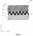
- FIG. 4 is a schematic vertical section of an essential part of a high-pressure gas container 100 of the present embodiment. As is understood from FIG. 4 , clearances 16 are formed between parts of the carbon fiber material P1 wound at the relatively low winding density as described above.
- the carbon fiber material P1 is wound to overlap in two stages in a container radial direction (Y-axis direction) and slightly offset in the positions of the carbon fiber material P1 in the upper stage and the carbon fiber material P1 in the lower stage in a container axial direction (X-axis direction).
- the clearances 16 are formed between parts of the carbon fiber material P1 adjacent to each other in both upper and lower stages. It should be noted that the number and size of these clearances 16 can be arbitrarily set such as by adjusting the winding density of the carbon fiber material P1.
- gas permeated into the gas ventilation part 14 through an inner layer liner 11 moves to a gas discharge port 15-1 or 15-2 and is discharged to outside with the aforementioned clearances 16 formed between the parts of the carbon fiber material P1 serving as a path (see a bent arrow B of FIG. 4 ).
- the outer layer 12 of the present embodiment is wound on the inner layer liner 11 from above the roughly wound carbon fiber material P1. It should be noted that since the outer layer 12 is required to have a high gas barrier property, the winding density of the carbon fiber material P2 in the outer layer 12 is higher than that of the carbon fiber material P1 of the gas ventilation part 14 as described above.
- the gas ventilation part 14 serving as the porous body is formed by winding the fiber material P1 on the inner layer liner 11 at the winding density lower than the winding density of the fiber material constituting the outer layer 12.
- the gas ventilation part 14 is formed by winding the fiber material P1 on the inner layer liner 11 such that a number of the clearances 16 of a size to ensure the gas permeability of the gas ventilation part 14 are formed.
- the gas ventilation part 14 serving as the porous body can be configured by a simple method of relatively roughly winding the fiber material P1 without using a cumbersome manufacturing process or an expensive material.
- the same carbon fiber material as the fiber material P2 constituting the outer layer 12 is used as the fiber material P1 constituting the gas ventilation part 14.
- a process for configuring the gas ventilation part 14 and a process for configuring the outer layer 12 follow the same steps except the number of windings of the fiber material.
- a transition can be made from a step of winding the fiber material P1 to configure the gas ventilation part 14 to a step of winding the fiber material P2 to configure the outer layer 12 as one of a series of steps.
- a manufacturing process of the entire high-pressure gas container 100 configured with the gas ventilation part 14 is more simplified.
- FIG. 5 is a schematic configuration diagram of a high-pressure gas container according to the fourth embodiment of the present invention, particularly a schematic vertical sectional view of an essential part of a high-pressure gas container 100 of the present embodiment.
- a gas ventilation part 14 serving as a porous body is constituted of a hollow fiber membrane.
- the hollow fiber membrane is a polymer membrane constituted of a pipe-like member having a plurality of fine hole parts (e.g. having a diameter of 1 ⁇ m or shorter) formed in a side wall.
- the gas ventilation part 14 formed of the hollow fiber membrane entirely covers an inner layer outer peripheral surface 11c as in the second embodiment.
- an outer layer 12 is formed by being wound on an outer peripheral surface 14c of the gas ventilation part 14 formed of the hollow fiber membrane entirely covering the inner layer outer peripheral surface 11c in this way.
- the gas ventilation part 14 serving as the porous body is constituted of the hollow fiber membrane.
- the interior of the hollow fiber membrane and the fine hole parts formed in the side wall of the hollow fiber membrane can serve as paths for allowing gas permeating through the inner layer liner 11 to move to a gas discharge port 15-1 or 15-2.
- a gas ventilation function in the gas ventilation part 14 can be more reliably exhibited.
- the hollow fiber membrane can be applied to the inner layer liner 11 by being wound using a predetermined winding device or the like.
- a hollow fiber membrane can be wound using a facility and a method for winding a carbon fiber material constituting the outer layer 12 or similar facility and method.
- FIG. 6 is a schematic configuration diagram of a high-pressure gas container 100 according to the fifth embodiment of the present invention, particularly a schematic vertical sectional view of an essential part of the high-pressure gas container 100 of the present embodiment.
- a gas ventilation part 14 serving as a porous body is constituted of a water-repellent resin material.
- the gas ventilation part 14 constituted of the water-repellent resin material entirely covers an inner layer outer peripheral surface 11c as in the second embodiment.
- an outer layer 12 is formed by winding a carbon fiber P2 impregnated with resin on an outer peripheral surface 14c of the gas ventilation part 14 entirely covering the inner layer outer peripheral surface 11c in this way.
- the water-repellent resin material in the present embodiment is, for example, a material formed by compounding an e-PTFE film formed by drawing polytetrafluoroethylene (PTFE) and polyurethane polymer.
- This material has, for example, about 1.4 ⁇ 10 8 fine hole parts (e.g. having a diameter of less than 1 ⁇ m) per cm 2 .
- the above hole parts are formed to have a diameter capable of blocking the passage of resin components and water of liquid while allowing the passage of hydrogen supposed as gas in the present embodiment.
- An example of such a material is Goretex (registered trademark).
- the gas ventilation part 14 a water repellent function of blocking liquid such as moisture is realized while a function of causing the gas having permeated through the inner layer liner 11 to pass and move to a gas discharge port 15-1 or 15-2 is ensured.
- the gas ventilation part 14 is configured to prevent the permeation of liquid while allowing the permeation of the gas.
- the gas ventilation part 14 is constituted of the water-repellent material. In this way, it is possible to prevent the penetration of, for example, the resin impregnated in the outer layer 12 or moisture produced by dew condensation or the like into the gas ventilation part 14 while ensuring a ventilation function in the gas ventilation part 14.
- the water-repellent material according to the present embodiment is a material formed with a plurality of fine hole parts having such a diameter as to block the liquid while allowing the passage of the gas, the penetration of the resin and moisture described above is blocked and the clogging of the hole parts is prevented. By preventing the clogging of the hole parts in this way, an original function of the gas ventilation part 14 to allow the passage of the gas can be reliably exhibited without being impaired.
- the outer layer 12 is formed by winding the carbon fiber P2 impregnated with resin on the gas ventilation part 14 in the present embodiment, it is supposed that tension is applied to the resin-impregnated carbon fiber and the liquid resin impregnated therein is squeezed toward the gas ventilation part 14 during a winding operation.
- the liquid resin moves toward the gas ventilation part 14 as just described, the liquid resin is suitably blocked by a part of the outer peripheral surface 14c of the gas ventilation part 14 by the action of the above water-repellent material.
- a phenomenon so-called splashing in which moisture splashed during travel reaches the high-pressure gas container 100 may occur when this vehicle travels such as in rainy weather.
- water-repellent material according to the present embodiment is illustrative and other arbitrary materials having a similar water repellent function can be used besides this water-repellent material.
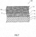
- FIG. 7 is a schematic configuration diagram of a high-pressure gas container 100 according to the sixth embodiment of the present invention, particularly a schematic vertical sectional view of an essential part of the high-pressure gas container 100 of the present embodiment.
- a gas ventilation part 14 between an inner layer liner 11 and an outer layer 12 is constituted of a fiber material P1 not impregnated with resin.
- the fiber material P1 constituting the gas ventilation part 14 is the same type of carbon fiber material as a fiber material P2 constituting the outer layer 12.
- the fiber material P1 constituting the gas ventilation part 14 is not impregnated with liquid resin such as epoxy resin unlike the outer layer 12.
- the gas ventilation part 14 is configured by winding the fiber material P1 not impregnated with resin on the inner layer liner 11.
- the gas ventilation part 14 configured by winding the fiber material P1 not impregnated with resin in this way has a lower airtightness than the outer layer 12 configured by winding the fiber material P2 impregnated with resin. Specifically, the gas ventilation part 14 has a higher ventilation performance than the outer layer 12.
- the outer layer 12 is formed of the fiber material P2 impregnated with resin and the gas ventilation part 14 is formed of the fiber material P1 not impregnated with resin.
- a ventilation function of the gas ventilation part 14 can be ensured by an easy method of using the fiber material P1 not impregnated with resin without using a cumbersome manufacturing process or an expensive material.
- the outer layer 12 and the gas ventilation part 14 are constituted of the same type of carbon fiber materials although these materials differ in resin impregnation. Thus, it is sufficient to perform the same manufacturing process (winding operation) in configuring the outer layer 12 and the gas ventilation part 14, wherefore a manufacturing process is simplified.
- the permeability of the gas ventilation part 14 is ensured in the present embodiment since the fiber material P1 constituting the gas ventilation part 14 is not impregnated with resin.
- a winding density of the fiber material P1 is preferably adjusted to be not too high in terms of ensuring a certain level of ventilation performance of the gas ventilation part 14 or higher.
- the winding density of the fiber material P1 constituting the gas ventilation part 14 is preferably lower than that of the fiber material P2 constituting the outer layer 12 as in the third embodiment. Coupled with the fact that the fiber material P1 constituting the gas ventilation part 14 is not impregnated with resin, this can more satisfactorily ensure the ventilation performance of the gas ventilation part 14.
- the permeability of the gas ventilation part 14 is ensured by not impregnating the fiber material P1 with resin as described above in the present embodiment, it is also possible to set a certain high winding density.
- a function of supporting the tension of the outer layer 12 may be further enhanced by setting a certain high winding density of the fiber material P1 to maximally prevent the formation of clearances between the inner layer liner 11 and the outer layer 12.
- a seventh embodiment is described below.
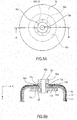
- FIG. 8A is a schematic plan view of a high-pressure gas container 100 according to the seventh embodiment of the present invention
- FIG. 8B is a schematic vertical sectional view along line B-B of FIG. 8A near one boss part 13 of the high-pressure gas container 100.
- hyphenated signs such as "boss parts 13-1, 13-2" used in the first to sixth embodiments are omitted and signs are unified into those such as "boss parts 13" without distinguishing the components.
- a basic configuration of a container body composed of an inner layer liner 11, an outer layer 12 and a gas ventilation part 14 is similar to that of the high-pressure gas container 100 according to the second embodiment described above.
- the boss part 13 includes an annular part 13c on a base end side part thereof, and a plurality of (eight in FIG. 8A ) radially arranged rib parts 13d are provided in a circumferential direction of the boss part 13 on the upper surface of this annular part 13c.
- An end part 11d of the inner layer liner 11 on the side of the boss part 13 and an end part 14d of the gas ventilation part 14 on the side of the boss part 13 are in contact with tip parts of the rib parts 13d.
- the outer layer 12 is formed to cover partial areas, i.e. about 3/4 areas in the present embodiment, of the upper surfaces of the rib parts 13d.
- gas permeating through the inner layer liner 11 and moving to the boss part 13 through the gas ventilation part 14 is introduced into the spaces 20 between the plurality of arranged rib parts 13d, move into the above clearance communicating with these spaces 20 and is finally discharged to the outside of the container.
- a gas discharge port 15 is formed by the above clearance and the spaces 20.
- a ratio of the outer layer 12 covering an upper surface area of the rib part 13d can be arbitrarily adjusted as long as the open part 12a is ensured.
- the ratio of the outer layer 12 covering the upper surface area of the rib part 13d can be set at 0 to 95 % to the entire upper surface area. Particularly, this ratio preferably exceeds 50 %.
- a relatively thick part 13e is formed on a tip side part of the boss part 13. This causes a gas passage area to be narrowed by being surrounded by an edge part of the open part 12a of the outer layer 12, the boss outer peripheral surface 13a and the thick part 13e. In this way, the discharge of the gas from the gas discharge part 15 is promoted by a so-called venturi effect.
- the boss part 13 is formed with the rib parts 13d arranged at each predetermined interval along the circumferential direction of the boss part 13. In this way, strength around the boss part 13 is improved. Particularly, since the rib parts 13d are arranged at each predetermined interval along the circumferential direction of the boss part 13, the spaces 20 formed between the rib parts 13d adjacent in this circumferential direction can be utilized as parts of the gas discharge port 15.
- the outer layer 12 is formed to partially cover the upper surface areas of the rib parts 13d. In this way, by extending the outer layer 12 fulfilling a function of reinforcing the inner layer liner 11 to partially cover the upper surface areas of the rib parts 13d, this reinforcing function can be more suitably exhibited.
- the edge part of the open part 12a of the outer layer 12, the end part 11d of the inner layer liner 11 on the side of the boss part and the end part 14d of the gas ventilation part 14 on the side of the boss part may be, for example, formed to be flush with each other so that the outer layer 12 does not cover the upper surface areas of the rib parts 13d at all. In this way, the number of windings of the carbon fiber constituting the outer layer 12 can be reduced.
- the number of the rib parts 13d is not limited to eight and can be appropriately adjusted in consideration of levels of the gas discharge performance in the gas discharge port 15 and the reinforcing function by the rib parts 13d. Further, it is also possible to adjust a width of the rib parts 13d.
- the above embodiments are merely an illustration of some application examples of the present invention and not intended to limit the technical scope of the present invention to the specific configurations of the above embodiments.
- a container configured to store the hydrogen gas and to be installed in the fuel cell vehicle is supposed as the high-pressure gas container 100 in the above embodiments, there is no limitation to this and the configuration of the present invention may be applied to high-pressure gas containers for storing other types of gases and high-pressure gas containers used in applications other than fuel cell vehicles.
- the configuration of the gas ventilation part 14 is not limited to those of the above first to seventh embodiments.
- the gas ventilation part 14 may be configured by projections provided at each predetermined interval on the outer peripheral surface 11c of the inner layer liner 11. In this case, the gas ventilation function is ensured by clearances between adjacent ones of the projections while the tension of the outer layer 12 is maintained by these projections.
- the inner layer liner 11 may be molded to integrally include the above projections.
Landscapes
- Engineering & Computer Science (AREA)
- Mechanical Engineering (AREA)
- General Engineering & Computer Science (AREA)
- Filling Or Discharging Of Gas Storage Vessels (AREA)
- Pressure Vessels And Lids Thereof (AREA)
Priority Applications (1)
| Application Number | Priority Date | Filing Date | Title |
|---|---|---|---|
| EP18192009.1A EP3447357A1 (fr) | 2015-05-26 | 2015-05-26 | Récipient de gaz à haute pression |
Applications Claiming Priority (1)
| Application Number | Priority Date | Filing Date | Title |
|---|---|---|---|
| PCT/JP2015/065128 WO2016189664A1 (fr) | 2015-05-26 | 2015-05-26 | Contenant de gaz haute pression |
Related Child Applications (2)
| Application Number | Title | Priority Date | Filing Date |
|---|---|---|---|
| EP18192009.1A Division-Into EP3447357A1 (fr) | 2015-05-26 | 2015-05-26 | Récipient de gaz à haute pression |
| EP18192009.1A Division EP3447357A1 (fr) | 2015-05-26 | 2015-05-26 | Récipient de gaz à haute pression |
Publications (3)
| Publication Number | Publication Date |
|---|---|
| EP3306174A1 true EP3306174A1 (fr) | 2018-04-11 |
| EP3306174A4 EP3306174A4 (fr) | 2018-04-11 |
| EP3306174B1 EP3306174B1 (fr) | 2019-11-27 |
Family
ID=57393853
Family Applications (2)
| Application Number | Title | Priority Date | Filing Date |
|---|---|---|---|
| EP15893299.6A Active EP3306174B1 (fr) | 2015-05-26 | 2015-05-26 | Contenant de gaz haute pression |
| EP18192009.1A Withdrawn EP3447357A1 (fr) | 2015-05-26 | 2015-05-26 | Récipient de gaz à haute pression |
Family Applications After (1)
| Application Number | Title | Priority Date | Filing Date |
|---|---|---|---|
| EP18192009.1A Withdrawn EP3447357A1 (fr) | 2015-05-26 | 2015-05-26 | Récipient de gaz à haute pression |
Country Status (7)
| Country | Link |
|---|---|
| US (1) | US10415753B2 (fr) |
| EP (2) | EP3306174B1 (fr) |
| JP (1) | JP6458865B2 (fr) |
| KR (2) | KR102116268B1 (fr) |
| CN (1) | CN107614961A (fr) |
| CA (1) | CA2987106C (fr) |
| WO (1) | WO2016189664A1 (fr) |
Cited By (2)
| Publication number | Priority date | Publication date | Assignee | Title |
|---|---|---|---|---|
| KR20210073600A (ko) * | 2018-11-30 | 2021-06-18 | 플라스틱 옴니엄 어드벤스드 이노베이션 앤드 리서치 | 자동차용 가압 유체 저장 탱크용 내부 인클로저 |
| EP4012247A4 (fr) * | 2019-08-07 | 2022-10-05 | Iljin Hysolus Co., Ltd. | Récipient sous pression et son procédé de fabrication |
Families Citing this family (22)
| Publication number | Priority date | Publication date | Assignee | Title |
|---|---|---|---|---|
| DE102014016023B3 (de) * | 2014-10-29 | 2016-03-24 | Daimler Ag | Druckgasbehälter |
| EP3306174B1 (fr) * | 2015-05-26 | 2019-11-27 | Nissan Motor Co., Ltd. | Contenant de gaz haute pression |
| AU2017246380A1 (en) * | 2016-04-06 | 2018-10-04 | Hexagon Technology As | Pressure vessel vented boss with sintered metal plug |
| US10088110B2 (en) | 2016-05-17 | 2018-10-02 | Hexagon Technology As | Pressure vessel liner venting via nanotextured surface |
| DE102016220995A1 (de) | 2016-10-25 | 2018-04-26 | Bayerische Motoren Werke Aktiengesellschaft | Druckbehälter mit einem Auslass für zwischen einem Liner und einer faserverstärkten Schicht angesammelten Brennstoff |
| JP6503394B2 (ja) * | 2017-03-17 | 2019-04-17 | 本田技研工業株式会社 | 高圧タンク |
| JP6599393B2 (ja) * | 2017-03-17 | 2019-10-30 | 本田技研工業株式会社 | 高圧タンク |
| DE102018206345A1 (de) * | 2018-04-25 | 2019-10-31 | Robert Bosch Gmbh | Schmelzsicherung, Gasbehälter und Verfahren zum Zusammenbauen einer Schmelzsicherung und zum Einbauen derselben in einen Gasbehälter |
| JP7197400B2 (ja) * | 2019-02-21 | 2022-12-27 | トヨタ自動車株式会社 | 高圧ガスタンクおよび高圧ガスタンクの製造方法 |
| US11559964B2 (en) * | 2019-06-06 | 2023-01-24 | Northrop Grumman Systems Corporation | Composite structures, composite storage tanks, vehicles including such composite storage tanks, and related systems and methods |
| JP6896800B2 (ja) * | 2019-06-28 | 2021-06-30 | 本田技研工業株式会社 | 高圧ガス容器 |
| EP3990819B1 (fr) * | 2019-06-28 | 2024-03-13 | Linamar Corporation | Atténuation d'affaissement de doublure pour récipients sous pression adaptables de type iv |
| JP6941648B2 (ja) * | 2019-08-23 | 2021-09-29 | 本田技研工業株式会社 | 高圧タンク |
| US11299036B2 (en) * | 2019-11-06 | 2022-04-12 | GM Global Technology Operations LLC | Hydrogen storage tank having a nanoporous breather layer |
| JP7226346B2 (ja) * | 2020-01-09 | 2023-02-21 | トヨタ自動車株式会社 | 高圧タンクの製造方法およびその製造装置 |
| JP7334641B2 (ja) * | 2020-02-10 | 2023-08-29 | トヨタ自動車株式会社 | 高圧タンクの製造方法 |
| KR102869087B1 (ko) * | 2020-03-16 | 2025-10-13 | 현대자동차주식회사 | 압력용기 및 그 제조방법 |
| KR102387017B1 (ko) * | 2020-07-30 | 2022-04-14 | 재단법인 중소조선연구원 | 수소탱크 일체형 선박 |
| CN112303230A (zh) * | 2020-10-13 | 2021-02-02 | 大连理工大学 | 一种新型薄壁高压压力容器 |
| FR3128153A1 (fr) * | 2021-10-18 | 2023-04-21 | Airbus | Structure composite pourvue d’un dispositif de protection thermique à fibres creuses, en particulier pour un réservoir à hydrogène liquide. |
| FR3129386A1 (fr) * | 2021-11-25 | 2023-05-26 | Airbus | Réservoir à hydrogène pourvu d’un système de capture d’hydrogène gazeux. |
| TW202413787A (zh) * | 2022-08-01 | 2024-04-01 | 日商東洋工程股份有限公司 | 壓縮空氣儲存容器、壓縮空氣儲存裝置、壓縮空氣儲存裝置之使用方法、發電裝置、發電方法 |
Family Cites Families (17)
| Publication number | Priority date | Publication date | Assignee | Title |
|---|---|---|---|---|
| JPWO2005022026A1 (ja) * | 2003-08-28 | 2006-10-26 | 三菱レイヨン株式会社 | 高性能圧力容器および圧力容器用炭素繊維 |
| JP2008190699A (ja) | 2007-02-07 | 2008-08-21 | Toyota Motor Corp | 燃料電池システム及び燃料ガスタンク |
| JP2009174700A (ja) * | 2007-06-14 | 2009-08-06 | Toyota Motor Corp | ガスタンク |
| US7870971B2 (en) * | 2007-08-29 | 2011-01-18 | GM Global Technology Operations LLC | Diffusion layer for pressure vessels |
| JP4580994B2 (ja) * | 2008-02-07 | 2010-11-17 | 本田技研工業株式会社 | 高圧タンク |
| JP5071801B2 (ja) * | 2008-03-31 | 2012-11-14 | トヨタ自動車株式会社 | 高圧タンクとその製造方法 |
| JP5168677B2 (ja) | 2008-11-18 | 2013-03-21 | トヨタ自動車株式会社 | 高圧タンク |
| WO2010091062A1 (fr) * | 2009-02-06 | 2010-08-12 | Lincoln Composites, Inc. | Évents longitudinaux pour récipient sous pression |
| FR2956185B1 (fr) * | 2010-02-11 | 2012-05-04 | Air Liquide | Reservoir composite et ensemble comprenant un tel reservoir et un organe receveur et/ou distributeur de gaz |
| WO2012074815A2 (fr) * | 2010-11-29 | 2012-06-07 | Mark Leavitt | Couche respirante pour évacuer un perméat à partir de récipients sous pression |
| JP2012127467A (ja) | 2010-12-17 | 2012-07-05 | Nagoya Oil Chem Co Ltd | 高圧ガス容器 |
| JP2012180892A (ja) | 2011-03-01 | 2012-09-20 | Toyota Motor Corp | ガスタンク及びガスタンクの製造方法 |
| DE102011103424A1 (de) * | 2011-06-07 | 2012-12-13 | Hydac Technology Gmbh | Druckbehälter |
| JP2014081014A (ja) | 2012-10-15 | 2014-05-08 | Honda Motor Co Ltd | 圧力ガス容器およびこれを備える車両 |
| KR20150121730A (ko) | 2014-03-26 | 2015-10-30 | 현대자동차주식회사 | 연료가스 저장탱크 및 제조방법 |
| EP3306174B1 (fr) * | 2015-05-26 | 2019-11-27 | Nissan Motor Co., Ltd. | Contenant de gaz haute pression |
| WO2017161085A1 (fr) * | 2016-03-16 | 2017-09-21 | Brian Yeggy | Raccord ventilé pour bossage de récipient sous pression |
-
2015
- 2015-05-26 EP EP15893299.6A patent/EP3306174B1/fr active Active
- 2015-05-26 JP JP2017520132A patent/JP6458865B2/ja not_active Expired - Fee Related
- 2015-05-26 KR KR1020197007081A patent/KR102116268B1/ko not_active Expired - Fee Related
- 2015-05-26 WO PCT/JP2015/065128 patent/WO2016189664A1/fr not_active Ceased
- 2015-05-26 EP EP18192009.1A patent/EP3447357A1/fr not_active Withdrawn
- 2015-05-26 CN CN201580080359.7A patent/CN107614961A/zh active Pending
- 2015-05-26 KR KR1020177036041A patent/KR20180004273A/ko not_active Ceased
- 2015-05-26 CA CA2987106A patent/CA2987106C/fr not_active Expired - Fee Related
- 2015-05-26 US US15/576,504 patent/US10415753B2/en not_active Expired - Fee Related
Cited By (3)
| Publication number | Priority date | Publication date | Assignee | Title |
|---|---|---|---|---|
| KR20210073600A (ko) * | 2018-11-30 | 2021-06-18 | 플라스틱 옴니엄 어드벤스드 이노베이션 앤드 리서치 | 자동차용 가압 유체 저장 탱크용 내부 인클로저 |
| KR102381103B1 (ko) | 2018-11-30 | 2022-03-31 | 플라스틱 옴니엄 뉴 에너지스 프랑스 | 자동차용 가압 유체 저장 탱크용 내부 인클로저 |
| EP4012247A4 (fr) * | 2019-08-07 | 2022-10-05 | Iljin Hysolus Co., Ltd. | Récipient sous pression et son procédé de fabrication |
Also Published As
| Publication number | Publication date |
|---|---|
| CA2987106C (fr) | 2019-07-02 |
| KR102116268B1 (ko) | 2020-05-29 |
| KR20190028576A (ko) | 2019-03-18 |
| EP3306174B1 (fr) | 2019-11-27 |
| JPWO2016189664A1 (ja) | 2018-04-26 |
| US20180172207A1 (en) | 2018-06-21 |
| CA2987106A1 (fr) | 2016-12-01 |
| JP6458865B2 (ja) | 2019-02-06 |
| WO2016189664A1 (fr) | 2016-12-01 |
| CN107614961A (zh) | 2018-01-19 |
| US10415753B2 (en) | 2019-09-17 |
| EP3306174A4 (fr) | 2018-04-11 |
| EP3447357A1 (fr) | 2019-02-27 |
| KR20180004273A (ko) | 2018-01-10 |
Similar Documents
| Publication | Publication Date | Title |
|---|---|---|
| EP3306174B1 (fr) | Contenant de gaz haute pression | |
| US9261239B2 (en) | Pressure gas container and vehicle including the same | |
| CN108779894B (zh) | 用于压力容器凸台的排放配件 | |
| US11761589B2 (en) | Pressure vessel longitudinal vents | |
| JP5071801B2 (ja) | 高圧タンクとその製造方法 | |
| EP1970258A1 (fr) | Element de ventilateur et structure de ventilateur | |
| US10627048B2 (en) | Pressure vessel dome vents | |
| CN111231374A (zh) | 制造高压容器的方法 | |
| KR102364916B1 (ko) | 일체형 배플을 갖는 탱크 보강물 | |
| US20190257473A1 (en) | High pressure tank and method of manufacturing same | |
| KR20160131038A (ko) | 통기성 용기용 덮개, 통기성 용기 및 통기성 용기용 덮개의 제조 방법 | |
| CN107921863B (zh) | 包括被紧固的构件的液体车辆储箱 | |
| JPH02144135A (ja) | 送風装置 | |
| US20190329202A1 (en) | Pressure vessel | |
| JP2009082602A (ja) | 収容容器 | |
| KR102598547B1 (ko) | 압력 용기 및 압력 용기의 제조 방법 | |
| JP2020118288A (ja) | 水素タンク | |
| EP0706954A1 (fr) | Procédé de fabrication d'un capuchon d'évacuation d'air et capuchon obtenu par ce procédé | |
| JP2021167653A (ja) | 高圧タンクの製造方法 | |
| JP5637780B2 (ja) | Frp製品の真空含浸成形方法及びその製造装置 | |
| JP2017145920A (ja) | タンク搭載構造 | |
| KR20130134925A (ko) | 필름 권취용 코어 |
Legal Events
| Date | Code | Title | Description |
|---|---|---|---|
| STAA | Information on the status of an ep patent application or granted ep patent |
Free format text: STATUS: THE INTERNATIONAL PUBLICATION HAS BEEN MADE |
|
| PUAI | Public reference made under article 153(3) epc to a published international application that has entered the european phase |
Free format text: ORIGINAL CODE: 0009012 |
|
| STAA | Information on the status of an ep patent application or granted ep patent |
Free format text: STATUS: REQUEST FOR EXAMINATION WAS MADE |
|
| 17P | Request for examination filed |
Effective date: 20171215 |
|
| A4 | Supplementary search report drawn up and despatched |
Effective date: 20180302 |
|
| AK | Designated contracting states |
Kind code of ref document: A1 Designated state(s): AL AT BE BG CH CY CZ DE DK EE ES FI FR GB GR HR HU IE IS IT LI LT LU LV MC MK MT NL NO PL PT RO RS SE SI SK SM TR |
|
| AX | Request for extension of the european patent |
Extension state: BA ME |
|
| DAV | Request for validation of the european patent (deleted) | ||
| DAX | Request for extension of the european patent (deleted) | ||
| STAA | Information on the status of an ep patent application or granted ep patent |
Free format text: STATUS: EXAMINATION IS IN PROGRESS |
|
| 17Q | First examination report despatched |
Effective date: 20190102 |
|
| GRAP | Despatch of communication of intention to grant a patent |
Free format text: ORIGINAL CODE: EPIDOSNIGR1 |
|
| STAA | Information on the status of an ep patent application or granted ep patent |
Free format text: STATUS: GRANT OF PATENT IS INTENDED |
|
| INTG | Intention to grant announced |
Effective date: 20190819 |
|
| GRAS | Grant fee paid |
Free format text: ORIGINAL CODE: EPIDOSNIGR3 |
|
| GRAA | (expected) grant |
Free format text: ORIGINAL CODE: 0009210 |
|
| STAA | Information on the status of an ep patent application or granted ep patent |
Free format text: STATUS: THE PATENT HAS BEEN GRANTED |
|
| AK | Designated contracting states |
Kind code of ref document: B1 Designated state(s): AL AT BE BG CH CY CZ DE DK EE ES FI FR GB GR HR HU IE IS IT LI LT LU LV MC MK MT NL NO PL PT RO RS SE SI SK SM TR |
|
| REG | Reference to a national code |
Ref country code: GB Ref legal event code: FG4D |
|
| RIN1 | Information on inventor provided before grant (corrected) |
Inventor name: TAKEMOTO, SHINICHIRO Inventor name: UEHARA, SHIGETAKA Inventor name: UCHIDA, HIROSHI |
|
| REG | Reference to a national code |
Ref country code: CH Ref legal event code: EP |
|
| REG | Reference to a national code |
Ref country code: AT Ref legal event code: REF Ref document number: 1207066 Country of ref document: AT Kind code of ref document: T Effective date: 20191215 |
|
| REG | Reference to a national code |
Ref country code: DE Ref legal event code: R096 Ref document number: 602015042757 Country of ref document: DE |
|
| REG | Reference to a national code |
Ref country code: IE Ref legal event code: FG4D |
|
| REG | Reference to a national code |
Ref country code: NL Ref legal event code: MP Effective date: 20191127 |
|
| REG | Reference to a national code |
Ref country code: LT Ref legal event code: MG4D |
|
| PG25 | Lapsed in a contracting state [announced via postgrant information from national office to epo] |
Ref country code: LT Free format text: LAPSE BECAUSE OF FAILURE TO SUBMIT A TRANSLATION OF THE DESCRIPTION OR TO PAY THE FEE WITHIN THE PRESCRIBED TIME-LIMIT Effective date: 20191127 Ref country code: GR Free format text: LAPSE BECAUSE OF FAILURE TO SUBMIT A TRANSLATION OF THE DESCRIPTION OR TO PAY THE FEE WITHIN THE PRESCRIBED TIME-LIMIT Effective date: 20200228 Ref country code: NO Free format text: LAPSE BECAUSE OF FAILURE TO SUBMIT A TRANSLATION OF THE DESCRIPTION OR TO PAY THE FEE WITHIN THE PRESCRIBED TIME-LIMIT Effective date: 20200227 Ref country code: NL Free format text: LAPSE BECAUSE OF FAILURE TO SUBMIT A TRANSLATION OF THE DESCRIPTION OR TO PAY THE FEE WITHIN THE PRESCRIBED TIME-LIMIT Effective date: 20191127 Ref country code: LV Free format text: LAPSE BECAUSE OF FAILURE TO SUBMIT A TRANSLATION OF THE DESCRIPTION OR TO PAY THE FEE WITHIN THE PRESCRIBED TIME-LIMIT Effective date: 20191127 Ref country code: SE Free format text: LAPSE BECAUSE OF FAILURE TO SUBMIT A TRANSLATION OF THE DESCRIPTION OR TO PAY THE FEE WITHIN THE PRESCRIBED TIME-LIMIT Effective date: 20191127 Ref country code: BG Free format text: LAPSE BECAUSE OF FAILURE TO SUBMIT A TRANSLATION OF THE DESCRIPTION OR TO PAY THE FEE WITHIN THE PRESCRIBED TIME-LIMIT Effective date: 20200227 Ref country code: FI Free format text: LAPSE BECAUSE OF FAILURE TO SUBMIT A TRANSLATION OF THE DESCRIPTION OR TO PAY THE FEE WITHIN THE PRESCRIBED TIME-LIMIT Effective date: 20191127 |
|
| PG25 | Lapsed in a contracting state [announced via postgrant information from national office to epo] |
Ref country code: IS Free format text: LAPSE BECAUSE OF FAILURE TO SUBMIT A TRANSLATION OF THE DESCRIPTION OR TO PAY THE FEE WITHIN THE PRESCRIBED TIME-LIMIT Effective date: 20200327 Ref country code: RS Free format text: LAPSE BECAUSE OF FAILURE TO SUBMIT A TRANSLATION OF THE DESCRIPTION OR TO PAY THE FEE WITHIN THE PRESCRIBED TIME-LIMIT Effective date: 20191127 Ref country code: HR Free format text: LAPSE BECAUSE OF FAILURE TO SUBMIT A TRANSLATION OF THE DESCRIPTION OR TO PAY THE FEE WITHIN THE PRESCRIBED TIME-LIMIT Effective date: 20191127 |
|
| PG25 | Lapsed in a contracting state [announced via postgrant information from national office to epo] |
Ref country code: AL Free format text: LAPSE BECAUSE OF FAILURE TO SUBMIT A TRANSLATION OF THE DESCRIPTION OR TO PAY THE FEE WITHIN THE PRESCRIBED TIME-LIMIT Effective date: 20191127 |
|
| PG25 | Lapsed in a contracting state [announced via postgrant information from national office to epo] |
Ref country code: ES Free format text: LAPSE BECAUSE OF FAILURE TO SUBMIT A TRANSLATION OF THE DESCRIPTION OR TO PAY THE FEE WITHIN THE PRESCRIBED TIME-LIMIT Effective date: 20191127 Ref country code: PT Free format text: LAPSE BECAUSE OF FAILURE TO SUBMIT A TRANSLATION OF THE DESCRIPTION OR TO PAY THE FEE WITHIN THE PRESCRIBED TIME-LIMIT Effective date: 20200419 Ref country code: EE Free format text: LAPSE BECAUSE OF FAILURE TO SUBMIT A TRANSLATION OF THE DESCRIPTION OR TO PAY THE FEE WITHIN THE PRESCRIBED TIME-LIMIT Effective date: 20191127 Ref country code: DK Free format text: LAPSE BECAUSE OF FAILURE TO SUBMIT A TRANSLATION OF THE DESCRIPTION OR TO PAY THE FEE WITHIN THE PRESCRIBED TIME-LIMIT Effective date: 20191127 Ref country code: RO Free format text: LAPSE BECAUSE OF FAILURE TO SUBMIT A TRANSLATION OF THE DESCRIPTION OR TO PAY THE FEE WITHIN THE PRESCRIBED TIME-LIMIT Effective date: 20191127 Ref country code: CZ Free format text: LAPSE BECAUSE OF FAILURE TO SUBMIT A TRANSLATION OF THE DESCRIPTION OR TO PAY THE FEE WITHIN THE PRESCRIBED TIME-LIMIT Effective date: 20191127 |
|
| REG | Reference to a national code |
Ref country code: DE Ref legal event code: R097 Ref document number: 602015042757 Country of ref document: DE |
|
| PG25 | Lapsed in a contracting state [announced via postgrant information from national office to epo] |
Ref country code: SK Free format text: LAPSE BECAUSE OF FAILURE TO SUBMIT A TRANSLATION OF THE DESCRIPTION OR TO PAY THE FEE WITHIN THE PRESCRIBED TIME-LIMIT Effective date: 20191127 Ref country code: SM Free format text: LAPSE BECAUSE OF FAILURE TO SUBMIT A TRANSLATION OF THE DESCRIPTION OR TO PAY THE FEE WITHIN THE PRESCRIBED TIME-LIMIT Effective date: 20191127 |
|
| REG | Reference to a national code |
Ref country code: AT Ref legal event code: MK05 Ref document number: 1207066 Country of ref document: AT Kind code of ref document: T Effective date: 20191127 |
|
| PLBE | No opposition filed within time limit |
Free format text: ORIGINAL CODE: 0009261 |
|
| STAA | Information on the status of an ep patent application or granted ep patent |
Free format text: STATUS: NO OPPOSITION FILED WITHIN TIME LIMIT |
|
| 26N | No opposition filed |
Effective date: 20200828 |
|
| PG25 | Lapsed in a contracting state [announced via postgrant information from national office to epo] |
Ref country code: SI Free format text: LAPSE BECAUSE OF FAILURE TO SUBMIT A TRANSLATION OF THE DESCRIPTION OR TO PAY THE FEE WITHIN THE PRESCRIBED TIME-LIMIT Effective date: 20191127 Ref country code: PL Free format text: LAPSE BECAUSE OF FAILURE TO SUBMIT A TRANSLATION OF THE DESCRIPTION OR TO PAY THE FEE WITHIN THE PRESCRIBED TIME-LIMIT Effective date: 20191127 Ref country code: AT Free format text: LAPSE BECAUSE OF FAILURE TO SUBMIT A TRANSLATION OF THE DESCRIPTION OR TO PAY THE FEE WITHIN THE PRESCRIBED TIME-LIMIT Effective date: 20191127 |
|
| PG25 | Lapsed in a contracting state [announced via postgrant information from national office to epo] |
Ref country code: LI Free format text: LAPSE BECAUSE OF NON-PAYMENT OF DUE FEES Effective date: 20200531 Ref country code: IT Free format text: LAPSE BECAUSE OF FAILURE TO SUBMIT A TRANSLATION OF THE DESCRIPTION OR TO PAY THE FEE WITHIN THE PRESCRIBED TIME-LIMIT Effective date: 20191127 Ref country code: CH Free format text: LAPSE BECAUSE OF NON-PAYMENT OF DUE FEES Effective date: 20200531 Ref country code: MC Free format text: LAPSE BECAUSE OF FAILURE TO SUBMIT A TRANSLATION OF THE DESCRIPTION OR TO PAY THE FEE WITHIN THE PRESCRIBED TIME-LIMIT Effective date: 20191127 |
|
| REG | Reference to a national code |
Ref country code: BE Ref legal event code: MM Effective date: 20200531 |
|
| PG25 | Lapsed in a contracting state [announced via postgrant information from national office to epo] |
Ref country code: LU Free format text: LAPSE BECAUSE OF NON-PAYMENT OF DUE FEES Effective date: 20200526 |
|
| PG25 | Lapsed in a contracting state [announced via postgrant information from national office to epo] |
Ref country code: IE Free format text: LAPSE BECAUSE OF NON-PAYMENT OF DUE FEES Effective date: 20200526 |
|
| PG25 | Lapsed in a contracting state [announced via postgrant information from national office to epo] |
Ref country code: BE Free format text: LAPSE BECAUSE OF NON-PAYMENT OF DUE FEES Effective date: 20200531 |
|
| PGFP | Annual fee paid to national office [announced via postgrant information from national office to epo] |
Ref country code: FR Payment date: 20210412 Year of fee payment: 7 Ref country code: DE Payment date: 20210427 Year of fee payment: 7 |
|
| PGFP | Annual fee paid to national office [announced via postgrant information from national office to epo] |
Ref country code: GB Payment date: 20210428 Year of fee payment: 7 |
|
| PG25 | Lapsed in a contracting state [announced via postgrant information from national office to epo] |
Ref country code: TR Free format text: LAPSE BECAUSE OF FAILURE TO SUBMIT A TRANSLATION OF THE DESCRIPTION OR TO PAY THE FEE WITHIN THE PRESCRIBED TIME-LIMIT Effective date: 20191127 Ref country code: MT Free format text: LAPSE BECAUSE OF FAILURE TO SUBMIT A TRANSLATION OF THE DESCRIPTION OR TO PAY THE FEE WITHIN THE PRESCRIBED TIME-LIMIT Effective date: 20191127 Ref country code: CY Free format text: LAPSE BECAUSE OF FAILURE TO SUBMIT A TRANSLATION OF THE DESCRIPTION OR TO PAY THE FEE WITHIN THE PRESCRIBED TIME-LIMIT Effective date: 20191127 |
|
| PG25 | Lapsed in a contracting state [announced via postgrant information from national office to epo] |
Ref country code: MK Free format text: LAPSE BECAUSE OF FAILURE TO SUBMIT A TRANSLATION OF THE DESCRIPTION OR TO PAY THE FEE WITHIN THE PRESCRIBED TIME-LIMIT Effective date: 20191127 |
|
| REG | Reference to a national code |
Ref country code: DE Ref legal event code: R119 Ref document number: 602015042757 Country of ref document: DE |
|
| GBPC | Gb: european patent ceased through non-payment of renewal fee |
Effective date: 20220526 |
|
| PG25 | Lapsed in a contracting state [announced via postgrant information from national office to epo] |
Ref country code: FR Free format text: LAPSE BECAUSE OF NON-PAYMENT OF DUE FEES Effective date: 20220531 |
|
| PG25 | Lapsed in a contracting state [announced via postgrant information from national office to epo] |
Ref country code: DE Free format text: LAPSE BECAUSE OF NON-PAYMENT OF DUE FEES Effective date: 20221201 Ref country code: GB Free format text: LAPSE BECAUSE OF NON-PAYMENT OF DUE FEES Effective date: 20220526 |