EP3306263A1 - Capteur confocal à codage chromatique de distance - Google Patents
Capteur confocal à codage chromatique de distance Download PDFInfo
- Publication number
- EP3306263A1 EP3306263A1 EP17191964.0A EP17191964A EP3306263A1 EP 3306263 A1 EP3306263 A1 EP 3306263A1 EP 17191964 A EP17191964 A EP 17191964A EP 3306263 A1 EP3306263 A1 EP 3306263A1
- Authority
- EP
- European Patent Office
- Prior art keywords
- beam splitter
- light
- pinhole
- distance sensor
- sensor according
- Prior art date
- Legal status (The legal status is an assumption and is not a legal conclusion. Google has not performed a legal analysis and makes no representation as to the accuracy of the status listed.)
- Granted
Links
Images

Classifications
-
- G—PHYSICS
- G01—MEASURING; TESTING
- G01J—MEASUREMENT OF INTENSITY, VELOCITY, SPECTRAL CONTENT, POLARISATION, PHASE OR PULSE CHARACTERISTICS OF INFRARED, VISIBLE OR ULTRAVIOLET LIGHT; COLORIMETRY; RADIATION PYROMETRY
- G01J3/00—Spectrometry; Spectrophotometry; Monochromators; Measuring colours
- G01J3/02—Details
- G01J3/0256—Compact construction
-
- G—PHYSICS
- G01—MEASURING; TESTING
- G01B—MEASURING LENGTH, THICKNESS OR SIMILAR LINEAR DIMENSIONS; MEASURING ANGLES; MEASURING AREAS; MEASURING IRREGULARITIES OF SURFACES OR CONTOURS
- G01B11/00—Measuring arrangements characterised by the use of optical techniques
- G01B11/002—Measuring arrangements characterised by the use of optical techniques for measuring two or more coordinates
- G01B11/005—Measuring arrangements characterised by the use of optical techniques for measuring two or more coordinates coordinate measuring machines
-
- G—PHYSICS
- G01—MEASURING; TESTING
- G01B—MEASURING LENGTH, THICKNESS OR SIMILAR LINEAR DIMENSIONS; MEASURING ANGLES; MEASURING AREAS; MEASURING IRREGULARITIES OF SURFACES OR CONTOURS
- G01B11/00—Measuring arrangements characterised by the use of optical techniques
- G01B11/02—Measuring arrangements characterised by the use of optical techniques for measuring length, width or thickness
- G01B11/026—Measuring arrangements characterised by the use of optical techniques for measuring length, width or thickness by measuring distance between sensor and object
-
- G—PHYSICS
- G01—MEASURING; TESTING
- G01J—MEASUREMENT OF INTENSITY, VELOCITY, SPECTRAL CONTENT, POLARISATION, PHASE OR PULSE CHARACTERISTICS OF INFRARED, VISIBLE OR ULTRAVIOLET LIGHT; COLORIMETRY; RADIATION PYROMETRY
- G01J3/00—Spectrometry; Spectrophotometry; Monochromators; Measuring colours
- G01J3/02—Details
- G01J3/0202—Mechanical elements; Supports for optical elements
-
- G—PHYSICS
- G01—MEASURING; TESTING
- G01J—MEASUREMENT OF INTENSITY, VELOCITY, SPECTRAL CONTENT, POLARISATION, PHASE OR PULSE CHARACTERISTICS OF INFRARED, VISIBLE OR ULTRAVIOLET LIGHT; COLORIMETRY; RADIATION PYROMETRY
- G01J3/00—Spectrometry; Spectrophotometry; Monochromators; Measuring colours
- G01J3/02—Details
- G01J3/0286—Constructional arrangements for compensating for fluctuations caused by temperature, humidity or pressure, or using cooling or temperature stabilization of parts of the device; Controlling the atmosphere inside a spectrometer, e.g. vacuum
-
- G—PHYSICS
- G01—MEASURING; TESTING
- G01J—MEASUREMENT OF INTENSITY, VELOCITY, SPECTRAL CONTENT, POLARISATION, PHASE OR PULSE CHARACTERISTICS OF INFRARED, VISIBLE OR ULTRAVIOLET LIGHT; COLORIMETRY; RADIATION PYROMETRY
- G01J3/00—Spectrometry; Spectrophotometry; Monochromators; Measuring colours
- G01J3/02—Details
- G01J3/0291—Housings; Spectrometer accessories; Spatial arrangement of elements, e.g. folded path arrangements
-
- G—PHYSICS
- G01—MEASURING; TESTING
- G01B—MEASURING LENGTH, THICKNESS OR SIMILAR LINEAR DIMENSIONS; MEASURING ANGLES; MEASURING AREAS; MEASURING IRREGULARITIES OF SURFACES OR CONTOURS
- G01B2210/00—Aspects not specifically covered by any group under G01B, e.g. of wheel alignment, caliper-like sensors
- G01B2210/50—Using chromatic effects to achieve wavelength-dependent depth resolution
Definitions
- the invention relates to a chromatic-confocal distance sensor in which the light source, the imaging optics and the spectrometer are arranged in the same housing.
- a distance sensor may have such small dimensions and be so light that it can be attached to a holder of a coordinate measuring machine (CMM, CMM).
- CMM coordinate measuring machine
- Chromatic confocal distance sensors have been used in industrial metrology for many years, when distances to object surfaces are to be measured without contact and with high accuracy. In the case of transparent objects, it is also possible to measure wall thicknesses or other thicknesses since, as a rule, a distance can be determined for each optical interface and the thickness results as the difference between the measured distances.
- Chromatic confocal distance sensors contain a light source that generates polychromatic measuring light and directs it to a pinhole.
- a pinhole is understood to mean any small opening from which light can exit and, if necessary, also reenter.
- the pinhole is imaged by an imaging optics on the surface to be measured. At least part of the imaging optics has a significant longitudinal chromatic aberration. Different-colored images of the pinhole are therefore arranged one behind the other on the optical axis of the imaging optics. Only the spectral portion of the measuring light, in which the image of the pinhole is exactly on the surface to be measured, is reflected back from this so that it in the same pinhole or an optically konjugiert arranged aperture can occur.
- the wavelength of this spectral component is detected by means of a spectrometer. Each wavelength is assigned a certain distance from the imaging optics. Although the other spectral components are also partially reflected by the object surface, they can not be focused by the imaging optics into the same or an optically conjugated pinhole and therefore do not contribute significantly to the part of the measurement light which is spectrally analyzed by the spectrometer.
- a chromatic-confocal distance sensor is known, which can be attached via an automatic change coupling to a holder of a coordinate measuring machine (CMM).
- CCM coordinate measuring machine
- the spatial coordinates of an object can be determined with high accuracy.
- coordinate measuring machines comprise a tactile measuring head, which is delivered to the object to be measured with the aid of a positioning system.
- the traverse paths are recorded with high accuracy by means of displacement and angle sensors.
- optical distance sensors have the advantage, among other things, that the measurement takes place without contact and therefore even very sensitive or soiled surfaces can be measured easily.
- a chromatic-confocal distance sensor In order to be interchangeable with a coordinate measuring machine, a chromatic-confocal distance sensor must meet some requirements that are not present in conventional sensors of this type. Thus, such a distance sensor must be very small and light so that it can be worn by the designed for the attachment of tactile sensors mounts the coordinate measuring machine.
- the entire volume of the distance sensor should ideally be less than about 350 cm 3 and the weight is less than about 500 g to be (conventional tactile sensors have in comparison, often only a volume of less than 20 cm 3 and a weight of less than 100 g).
- the small space also brings problems in terms of thermal management with it. Since a greater part of the electrical power consumed by the light source and the spectrometer is converted into heat within the housing, thermally induced deformations can impair measurement accuracy.
- the spectrometer, the imaging optics and the light source should be arranged in the same housing, so that the measuring light does not have to be guided over an additional optical fiber to outside the housing arranged assemblies. Namely, such a fiber would have to be guided over the automatic change coupling of the coordinate measuring machine, for which this is not established by default.
- the distance sensor which from the above-mentioned EP 2 667 152 B1 is known, meets these conditions only conditionally. Since the measuring light is guided in optical fibers, which can not be curved arbitrarily (especially in the area of fiber couplers), the distance sensor is so large and heavy that it can not be coupled to all coordinate measuring machines.
- Chromatic confocal distance sensors are known in which the measuring light passes through a beam splitter as a free jet.
- a free jet is understood to mean a light beam which is not guided in an optical fiber or another optical waveguide.
- the light source and the spectrometer are connected in these known distance sensors via optical fibers with a measuring head containing the free-jet beam splitter and the imaging optics. As a result, these distance sensors can not be automatically coupled to coordinate measuring machines.
- the object of the invention is to provide a chromatic-confocal distance sensor which has a high accuracy of measurement, but is so small and light that it can be attached to the holder of a coordinate measuring machine when needed.
- a chromatic-confocal distance sensor having a housing.
- a light source is arranged, which is adapted to produce polychromatic measuring light.
- an imaging optics having a longitudinal chromatic aberration, a spectrometer and a plane beam splitter surface arranged in the light path of the measuring light between the light source and the imaging optics and also in the light path of the measuring light, which reflects after passing through the imaging optics of a measured object has been, is arranged between the imaging optics and the spectrometer.
- first pinhole which is arranged in the light path between the light source and the beam splitter surface
- second pinhole which is arranged in the light path between the beam splitter surface and the spectrometer.
- the first pinhole and the second pinhole are arranged mirror-symmetrically with respect to the beam splitter surface. According to the measuring light propagates within the housing as a free jet.
- the beam splitter surface, the first pinhole and the second pinhole are also mounted together on a carrier having an isotropic coefficient of thermal expansion.
- the measuring light is guided at least partially in optical fibers, spreads in the distance sensor according to the invention, the measuring light within the housing completely as a free jet.
- the measuring light can be folded several times in all spatial directions with the help of reflecting surfaces, so that very small housing dimensions (for example 65 x 45 x 110 mm) and a correspondingly low weight of less than 400 g can be realized.
- the first pinhole and the second pinhole are mounted together on a carrier having an isotropic coefficient of thermal expansion. If it comes to a deformation of the carrier due to a change in temperature, the mirror-symmetrical arrangement of the pinhole on the common carrier because of its isotropic thermal expansion coefficient causes the optical paths between the beam splitter surface and the apertured always change uniformly. The optical conjugation between the pinholes is thus almost completely independent of the temperature. Consequently, temperature changes that are not completely avoidable as a result of the compact design can no longer lead to a significant impairment of the measurement accuracy.
- the beam splitter surface is the surface of a beam splitter, at which an incident light beam is separated into two sub-beams.
- the division takes place in terms of intensity; in the However, principle also a division according to polarization states into consideration.
- the beam splitter surface is one of the adjacent hypotenuse faces of the prisms carrying a metallic or dielectric coating. This coating determines the intensity ratio between the transmitted and the reflected beam.
- the beam splitter surface is the outer surface of the plate where the light is incident and partially reflected.
- Beam splitter cubes are preferred in comparison to beam splitter plates, because multiple reflections, additional astigmatism and coma can occur with beam splitter plates when exposed to a divergent beam.
- film dividers which consist of a membrane a few micrometers thick, which forms the beam splitter surface.
- the membrane can, for. B. made of nitrocellulose and is usually clamped in a support frame plan.
- the prisms, glass plates or support frames of such beam splitters are then also to be regarded as part of the carrier on which the pinhole diaphragms are arranged, and must therefore also have an at least approximately isotropic thermal expansion coefficient.
- the carrier is a z. B. plate-shaped support member, on which a beam splitter surface comprehensive beam splitter, the first pinhole and the second pinhole are attached.
- This support element can also be constructed in several parts.
- Each of the apertured diaphragms can be an opaque disk which has an aperture. Since such a diaphragm opening has a non-negligible axial extent, it may be advantageous if the first and the second pinhole each have a plate which carries a light-absorbing or reflective coating having an aperture.
- the aperture is very small and typically has a diameter between 10 microns and 50 microns.
- the coating may for example consist of chrome and be very thin.
- the plates are secured to support members, which in turn are secured to the support member.
- the support elements should be made of the same material.
- the support element, the support elements and the plates attached thereto are all made of the same material or of different materials, but have the same thermal expansion coefficient.
- the beam splitter and the pinholes can be omitted if the beam splitter is designed as a beam splitter cube.
- the prisms, which make up the beam splitter cube themselves form a carrier which ensures the desired spacing of the pinholes from the beam splitter surface.
- the pinhole diaphragms are then supported directly by outer surfaces of the two prisms.
- the respective outer surfaces of the prisms, with the exception of the aperture, can be coated in an absorbent or reflective manner.
- the measurement light impinges as a divergent beam on the beam splitter surface, because in this way less stray light enters the spectrometer and thereby the measurement accuracy is improved at least for those objects that reflect only a small measurement light due to a low reflection coefficient or an oblique object surface.
- the imaging optics comprise an objective which is interchangeably fixed to a part of the housing, wherein the measuring light coming from the direction of the light source enters the objective as a collimated beam.
- An interchangeable lens makes it possible to use lenses with different focal lengths and thereby adapt the measuring distance to the specific measuring task. Since the measuring light coming from the beam splitter enters the objective as a collimated beam, the precision requirements for coupling the objective to the rest of the housing are reduced.
- the spectrometer includes a detector array, a reflective diffraction grating, and spectrometer optics which image the second aperture on the detector array.
- the spectrometer optics is arranged in the light path of the measuring light in such a way that it is passed by the measuring light before and after reflection at the diffraction grating.
- a high-quality and multi-lens spectrometer optics can be used, which images the second pinhole sharp on the detector line and thus ensures high signal strengths.
- the housing has an automatic change coupling, with which the housing is automatically fastened to a holder of a coordinate measuring machine.
- the advantages of the very small and lightweight distance sensor can then be used for use in a coordinate measuring machine.
- the small and lightweight distance sensor can be used independently of coordinate measuring machines advantageous for all measurement tasks, where it depends on a small size and a small weight of the distance sensor.
- the FIG. 1 shows in a simplified meridional section the beam path of a distance sensor according to the invention and designated overall by S according to a first exemplary embodiment.
- the numeral 10 denotes a light source which is adapted to generate polychromatic measuring light ML.
- Polychromatic refers to light that is not monochromatic and thus does not consist only of light of a single wavelength.
- the spectrum of the polychromatic measuring light ML can be continuous or discrete.
- a white light LED is used as the light source 10, which generates a continuous spectrum between about 400 nm and 720 nm.
- the white-light LED emits the measuring light ML evenly over its entire plane light-emitting surface.
- the white light LED can be mounted on a special thermal bridge, which dissipates the heat loss from the back of the LED to an adjacent housing wall.
- an aperture stop 12 is arranged, with which the angle of the measuring light cone is limited.
- the aperture stop 12 prevents measurement light from entering the subsequent beam path, which can not be focused on the measurement object 14 to be measured, but without aperture stop 12 as a result of scattering or undesired multiple reflections, would lead to disturbing light which impairs the measurement accuracy.
- an interference light beam 16 is shown as an example, whose propagation through the aperture 12 is prevented.
- the measurement light ML passes through a first pinhole 18 whose structure is described below with reference to FIGS FIG. 2 is explained in more detail.
- the measuring light ML passing through the aperture 18 falls divergently onto a beam splitter cube 20, which in a manner known per se consists of two prisms 22, 24 which are cemented to one another along their hypotenuse surfaces by means of a resin layer.
- the beam splitter cube 20 causes in comparison to that in the FIG. 5 shown beam splitter plate no problems such as multiple reflections, additional Astigmatism and coma with divergent beam.
- the beam splitter cube 20 is designed so that the largest part of the measurement light ML without reflection passes through the beam splitter surface 26 and strikes an imaging optics 28, which consists of four lenses in the illustrated embodiment.
- a first lens 30 has positive refractive power and collimates the incident divergent measuring light ML.
- a second lens 32 has a negative refractive power and expands the measurement light ML.
- a third lens 34 again has positive refractive power and collimates the incident measuring light ML.
- a fourth lens 36 focuses the incident collimated measuring light ML in its focal plane.
- the lenses 30 and 32 have a negligible longitudinal chromatic aberration, and are preferably aspherical, a large dispersion material has been chosen for the third lens 34 and the fourth lens 36 so that these two lenses 34, 36 have a large longitudinal chromatic aberration.
- the lenses 34 and 36 may be formed as diffractive lenses, such as from the EP 2 500 685 A1 is known.
- the imaging optics 28 is optimized so that in each case a sharp and small focus is produced for all wavelengths within a larger wavelength range, wherein the focal points along the optical axis are arranged one behind the other.
- sharp and small foci are usually obtained only for a small wavelength range, while the light of other wavelengths is focused only into larger fuzzy spots.
- the second, third and fourth lenses 32, 34 and 36 are combined in a lens 38 which is interchangeably fixed by a screw thread on a housing part of the distance sensor S.
- a lens 38 which is interchangeably fixed by a screw thread on a housing part of the distance sensor S.
- an exchange lens 38 'indicated by dashed lines which can be exchanged for the lens 38.
- the fourth lens 36 'of the exchange objective 38' has a higher refractive power than the fourth lens 36 of the objective 38.
- the replacement objective 38 ' has a shorter focal length than the objective 38.
- the working distance can thus be changed by replacing the objective 38 in which the measurement object 14 is to be arranged relative to the objective 38 (or vice versa), are adapted to the respective measurement task. Because the measuring light ML collimated enters the lens 38, a slight transverse offset does not significantly affect the optical image. This reduces the requirements for the accuracy of the connection flange, with which the lens 38 is attached to the rest of the housing.
- Measuring light ML reflected by a surface 42 of the measuring object 14 is picked up by the imaging optics 28 and directed back onto the beam splitter cube 20.
- the reflected measurement light ML is partially reflected at the beam splitter surface 26.
- the reflected portion passes through a second pinhole 40 which is in an optically conjugate position to the surface 42 of the DUT 14.
- the imaging optics 28 thus form the first apertured diaphragm 18 via an intermediate image on the surface 42 of the test object 14 onto the second apertured diaphragm 40.
- the two pinhole apertures 18, 40 are optically conjugate.
- the measuring light ML passing through the pinhole aperture 40 passes via a folding mirror 43 into a spectrometer 44, which comprises a spectrometer optics 46, which is indicated here only with a lens, a reflexive diffraction grating 48 and a detector row 50 of light-sensitive detector pixels.
- the second pinhole 40 and the detector row 50 are located in the focal plane of the spectrometer optics 46, so that the measurement light ML after the first passage through the spectrometer optics 46 falls on the reflexive diffraction grating 48 in a collimated manner. After again passing through the spectrometer optics 46, the measuring light ML diffracted by the reflexive diffraction grating 48 is focused by the spectrometer optics 46 onto the detector row 50. Thus, the spectrometer optics 46 images the second aperture 40 onto the detector row 50.
- the measurement light ML enters the beam splitter cube 20 as a divergent beam.
- This is advantageous because it reduces the amount of disturbing light entering the spectrometer 44.
- a small portion (typically around 1%) of the incident measurement light ML is always reflected at the rear surface, ie, facing the measurement object 14.
- This measuring light reflected in the beam splitter cube 20 is reflected by the beam splitter surface 26 in the direction of the spectrometer 44 as stray light. In the case of an axis-parallel beam path, this disturbing light could be completely transmitted through the then required collecting lens second pinhole 40 enter the spectrometer and interfere with its measurement.
- the measurement light enters the beam splitter cube 20 as a divergent beam, only a very small part of this interference light is directed by the beam splitter surface 26 onto the opening of the second aperture 40; the rest of the stray light is blocked by the second pinhole 40.
- the reflected light beam reflected in the direction of the spectrometer 44 is greatly expanded when it hits the second aperture plate 40. Therefore, only a very small part of this disturbing light can enter the spectrometer and contribute to a disturbing noise floor.
- the distance measurement is carried out according to the known per se confocal chromatic measurement principle. Only measuring light ML of a specific wavelength is focused by the imaging optics 28 in a plane in which the surface 42 of the measuring object 14 is located. A portion of this measuring light is reflected by the surface 42 and focused by the imaging optics 28 on the second pinhole 40 so that it can be passed. Although light of other wavelengths is likewise reflected on the surface 42 of the measurement object 14, it can pass through the second pinhole aperture 40 only to a very small extent since it is not focused by the imaging optics 28 into the second aperture diaphragm 40.
- measuring light ML which has a specific wavelength
- the other wavelengths decrease in intensity significantly. Since the diffraction angle at the diffractive reflection grating 48 depends on the wavelength, the measuring light of this wavelength is deflected in a certain direction and focused by the spectrometer optics 46 at a point P which lies on the detector line 50.
- the considerably weaker remaining portions of the measuring light ML are diffracted in other directions and focused by the spectrometer optics 46 at other locations on the detector row 50, as shown in FIG FIG. 1 is indicated by dashed and dash-dotted lines.
- the distance to the surface 42 of the measurement object can be derived directly from the detected wavelengths.
- distance sensor S whose individual optical elements without sockets and brackets are shown.
- the optical elements are spatially very densely arranged, so that heat, which is generated in particular by the light source 10 and the detector row 50, can easily pass over to the sockets and holders of the optical elements.
- the arrangement of the two apertured apertures 18, 40 is particularly critical in this context. Since the apertures in the apertured apertures 18, 40 must be very small for a high lateral measuring resolution (the diameter is preferably between 10 .mu.m and 50 .mu.m), even the smallest temperature-induced relative displacements between the apertured apertures 18, 40 to the fact that the imaging optics 28, the first pinhole 18 can not accurately reflect on the second pinhole 40.
- the beam splitter cube 20 is fixed together with the pinhole apertures 18, 40 on a common plate-shaped support member 52, as shown in the perspective view of FIG. 2 is shown.
- the support element 52 has an isotropic coefficient of thermal expansion and, together with the components carried therefrom, forms a pinhole module 51 which, for adjustment purposes, preferably has a multi-part construction and can be fastened to or integrated in a housing wall of the distance sensor S.
- the first pinhole 18 comprises a transparent cuboid plate 54, which carries a light-absorbing coating 56.
- the coating 56 has a diaphragm opening 58, through which the measuring light can pass through the pinhole diaphragm 18.
- the plate 54 is fixed to a likewise cuboid support member 60 which is fixed to a surface of the support member 52. Since the light absorbing coating 56 is very thin, the aperture 58 has a negligible axial extent, so that the aperture effect does not depend on the angle of incidence of the incident light.
- the plates 54 are adhered to the support members 60 by means of a UV curing adhesive and were carefully adjusted to each other prior to bonding.
- the optical axes defined by the apertures 58 of the apertured apertures 18, 40 must intersect in the beam splitter cube 20 at a point on the beam splitter surface 26 so that the imaging optics 28 can precisely image the apertures 58 of the apertured apertures 18, 40.
- the second pinhole 40 is constructed identically.
- the diaphragm plane of the second pinhole, in which the absorbent coating 56 extends and which is aligned perpendicular to the optical axis, is aligned at right angles to the diaphragm plane of the first pinhole diaphragm 18.
- the beam splitter cube 20 is attached to a corner of the support member 52.
- pinhole apertures 18, 40 are arranged mirror-symmetrically with respect to the beam splitter surface 26.
- All components of the pinhole module 51 with the exception of the light-absorbing coatings 56 consist in the illustrated embodiment of quartz glass.
- Zerodur® which has an almost negligible coefficient of thermal expansion at the operating temperature of 20 ° C. usual for high-precision measurements, is also suitable. Since the light source 10 and the detector line 50 have a total power consumption in the range of a few watts, but so large temperature increases may occur that in the FIG. 2 thermally expand shown optical elements and especially their sockets and mounts.
- the pinhole apertures 18, 40 are arranged mirror-symmetrically to the beam splitter surface 26 of the beam splitter cube 20 on the carrier element 52, the relative arrangement between the pinhole apertures 18, 40 and the beam splitter surface 20 does not change with a thermally induced linear expansion. With such an extent, the image of the first pinhole diaphragm 18 therefore continues to lie exactly on the optical axis of the second pinhole diaphragm 40 and is only slightly shifted along the optical axis, but this is unproblematic because of the small numerical aperture of the measuring light ML and the associated great depth of field.
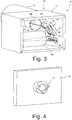
- FIG. 3 shows the distance sensor S according to the invention in a perspective and highly simplified representation. All in the Figures 1 and 2 shown optical elements are accommodated in a housing 70, the one in the FIG. 3 recognizable main body portion 72, the lens 38 receiving a removable housing part 74 and a only in the FIG. 4 shown housing rear wall 76 includes.
- the latter carries an automatic change coupling 78 for coupling the distance sensor S to a holder of a coordinate measuring machine, not shown.
- the pinhole diaphragm module 51, the first lens 30 of the imaging optics 28, a housing 80 of the spectrometer optics 46, the folding mirror 43 and the detector row 50 can be seen in the first housing part 72.
- a cutout 79 can be seen, through which the measuring light ML leaves the main housing part 72 in order to enter the exchangeable lens 38.
- Other parts such as an evaluation or a power supply are in the interests of clarity in the FIG. 3 not shown.
- here also versions and other mounts for the optical elements have been omitted.
- FIG. 3 In the perspective view of FIG. 3 a single axial measuring light beam ML is shown. It can be seen that the folding mirror 43 deflects the measuring light ML, after it has passed through the second pinhole 40 on the pinhole module 51, out of the beam plane in such a way that it propagates approximately parallel to the longitudinal direction of the housing 70. By interaction of the beam splitter surface 26 and the folding mirror 43, the measuring light ML reflected by the measuring object 14 is thus folded in three spatial directions, which allows an extremely compact construction.
- the distance sensor S is in the FIG. 3 reproduced approximately in the scale 1: 1, so that the dimensions shown there approximately correspond to the actual dimensions of the distance sensor S.
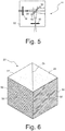
- the FIG. 5 shows a section of the beam path for another embodiment of a distance sensor according to the invention S.
- a beam splitter plate 90 is used as a beam splitter.
- the in the FIG. 5 The first plane surface of the beam splitter plate 90 pointing to the left forms the beam splitter surface 26, on which incident measuring light ML is partially reflected and with respect to which the apertured diaphragms 18, 40 are arranged in mirror symmetry. Usually, this plane surface is provided with a dielectric coating, with which the ratio between transmitted and reflected light can be determined.
- the in the FIG. 5 right-facing second plane surface 92 is provided with an antireflection coating, so that measurement light ML, which can pass through the first plane surface, is not reflected on the second plane surface.
- the FIG. 6 shows a perspective view of a beam splitter cube 20 'according to a third embodiment.
- the beam splitter cube 20 ' is basically the same as that in the FIG. 2 shown beam splitter cube 20 and thus also includes two interconnected prisms 22, 24, between which the beam splitter surface 26 extends.
- the light-absorbing coatings 56 provided with apertures 58 which form the apertured apertures 18, 40 are not supported by separate plates, but directly by outer surfaces of the beam splitter cube 20 '.
- the prisms 22, 24 of the beam splitter cube itself form a support for the pinhole apertures 18, 40, which has an isotropic thermal expansion coefficient.
Landscapes
- Physics & Mathematics (AREA)
- Spectroscopy & Molecular Physics (AREA)
- General Physics & Mathematics (AREA)
- Length Measuring Devices By Optical Means (AREA)
Applications Claiming Priority (1)
| Application Number | Priority Date | Filing Date | Title |
|---|---|---|---|
| US15/284,983 US10260941B2 (en) | 2016-10-04 | 2016-10-04 | Chromatic confocal distance sensor |
Publications (2)
| Publication Number | Publication Date |
|---|---|
| EP3306263A1 true EP3306263A1 (fr) | 2018-04-11 |
| EP3306263B1 EP3306263B1 (fr) | 2019-11-20 |
Family
ID=59914403
Family Applications (1)
| Application Number | Title | Priority Date | Filing Date |
|---|---|---|---|
| EP17191964.0A Active EP3306263B1 (fr) | 2016-10-04 | 2017-09-19 | Capteur confocal à codage chromatique de distance |
Country Status (4)
| Country | Link |
|---|---|
| US (1) | US10260941B2 (fr) |
| EP (1) | EP3306263B1 (fr) |
| JP (1) | JP6966285B2 (fr) |
| CN (1) | CN107894208B (fr) |
Cited By (2)
| Publication number | Priority date | Publication date | Assignee | Title |
|---|---|---|---|---|
| DE102021111892B3 (de) | 2021-05-06 | 2022-08-25 | 4D Photonics GmbH | Vorrichtung zur spektral aufgelösten Erfassung optischer Strahlung |
| WO2024133387A1 (fr) * | 2022-12-20 | 2024-06-27 | Precitec Optronik Gmbh | Dispositif de mesure confocal chromatique |
Families Citing this family (6)
| Publication number | Priority date | Publication date | Assignee | Title |
|---|---|---|---|---|
| DE102015217637C5 (de) * | 2015-09-15 | 2023-06-01 | Carl Zeiss Industrielle Messtechnik Gmbh | Betreiben eines konfokalen Weißlichtsensors an einem Koordinatenmessgerät und Anordnung |
| WO2019217735A1 (fr) * | 2018-05-11 | 2019-11-14 | Arizona Board Of Regents On Behalf Of The University Of Arizona | Module confocal chromatique compact à bas coût |
| US11293799B2 (en) | 2019-12-30 | 2022-04-05 | Palo Alto Research Center Incorporated | Chromatic confocal sensor |
| US12492889B2 (en) * | 2021-07-29 | 2025-12-09 | Mitutoyo Corporation | Chromatic range sensor system including camera |
| CN113686439A (zh) * | 2021-08-24 | 2021-11-23 | 熵智科技(深圳)有限公司 | 一种线光谱共焦传感器 |
| DE102021211046A1 (de) | 2021-09-30 | 2023-03-30 | Micro-Epsilon Optronic Gmbh | Spektrometer, Abstandsmesssystem sowie Verfahren zum Betreiben eines Spektrometers |
Citations (8)
| Publication number | Priority date | Publication date | Assignee | Title |
|---|---|---|---|---|
| JPH047502A (ja) * | 1990-04-25 | 1992-01-10 | Seiko Epson Corp | 光学素子及びホログラム露光方法 |
| US20020044287A1 (en) * | 2000-02-17 | 2002-04-18 | Nikon Corporation | Point diffraction interferometer, manufacturing method for reflecting mirror, and projection exposure apparatus |
| EP1398597A1 (fr) * | 2002-09-12 | 2004-03-17 | Siemens Aktiengesellschaft | Capteur confocal de mesure de distance |
| FR2930334A1 (fr) | 2008-04-22 | 2009-10-23 | Nanotec Solution Soc Civ Ile | Dispositif et procede d'analyse optique, appareil et procede de mesure chromatique associes |
| US20100296106A1 (en) * | 2007-10-11 | 2010-11-25 | Gates Brian J | Chromatic confocal sensor |
| FR2950441A1 (fr) | 2009-09-23 | 2011-03-25 | Sabban Youssef Cohen | Capteur optique dote de champ lateral pour la numerisation 3d |
| EP2500685A1 (fr) | 2011-03-14 | 2012-09-19 | Omron Corporation | Dispositif de mesure confocale |
| EP2667152B1 (fr) | 2012-05-25 | 2015-04-15 | Mitutoyo Corporation | Sonde de capteur de variation chromatique interchangeable pour machine de mesure de coordonnées |
Family Cites Families (30)
| Publication number | Priority date | Publication date | Assignee | Title |
|---|---|---|---|---|
| US3013467A (en) * | 1957-11-07 | 1961-12-19 | Minsky Marvin | Microscopy apparatus |
| US5223693A (en) * | 1990-04-28 | 1993-06-29 | Mitsubishi Denki Kabushiki Kaisha | Optical machining apparatus |
| US5537247A (en) * | 1994-03-15 | 1996-07-16 | Technical Instrument Company | Single aperture confocal imaging system |
| US7071477B2 (en) * | 1994-07-15 | 2006-07-04 | Baer Stephen C | Superresolution in microlithography and fluorescence microscopy |
| US6856457B2 (en) * | 2001-03-27 | 2005-02-15 | Prairie Technologies, Inc. | Single and multi-aperture, translationally-coupled confocal microscope |
| DE10137158B4 (de) * | 2001-07-30 | 2005-08-04 | Leica Microsystems Heidelberg Gmbh | Verfahren zur Scanmikroskopie und Scanmikroskop |
| US6657216B1 (en) * | 2002-06-17 | 2003-12-02 | Nanometrics Incorporated | Dual spot confocal displacement sensor |
| DE10231776B4 (de) * | 2002-07-13 | 2021-07-22 | Leica Microsystems Cms Gmbh | Verfahren zur Scanmikroskopie und Scanmikroskop |
| US7042556B1 (en) * | 2003-12-05 | 2006-05-09 | The United States Of America As Represented By The United States Department Of Energy | Device and nondestructive method to determine subsurface micro-structure in dense materials |
| US7102746B2 (en) * | 2003-12-16 | 2006-09-05 | New Chromex, Inc. | Raman spectroscope |
| EP1626571A1 (fr) * | 2004-08-13 | 2006-02-15 | STMicroelectronics Limited | Assemblage pour la formation d' images |
| US7684048B2 (en) * | 2005-11-15 | 2010-03-23 | Applied Materials Israel, Ltd. | Scanning microscopy |
| US7791712B2 (en) * | 2007-03-27 | 2010-09-07 | Mitutoyo Corporation | Chromatic confocal sensor fiber interface |
| ES2599902T3 (es) * | 2007-06-15 | 2017-02-06 | Novartis Ag | Sistema y método de microscopio para obtener datos de muestra normalizados |
| JP4935914B2 (ja) * | 2009-03-05 | 2012-05-23 | 横河電機株式会社 | 成分測定装置 |
| US8982455B2 (en) * | 2009-09-22 | 2015-03-17 | Intelligent Imaging Innovations, Inc. | Modular design of a scanning microscope attachment and accessories |
| US9791684B2 (en) * | 2010-01-06 | 2017-10-17 | Ecole polytechnique fédérale de Lausanne (EPFL) | Optical coherence microscopy system having a filter for suppressing a specular light contribution |
| JP5466569B2 (ja) * | 2010-04-26 | 2014-04-09 | 富士フイルム株式会社 | 撮像レンズおよび撮像装置 |
| WO2012035170A1 (fr) * | 2010-09-17 | 2012-03-22 | Lltech Inc. | Sectionnement de tissu optique au moyen d'une tomographie par cohérence optique plein champ |
| JP5518667B2 (ja) * | 2010-10-12 | 2014-06-11 | 浜松ホトニクス株式会社 | 距離センサ及び距離画像センサ |
| US8797529B2 (en) * | 2011-01-25 | 2014-08-05 | Ocean Optics, Inc. | Spectrometer design for aberration correction, simplified manufacture, and compact footprint |
| WO2013090738A1 (fr) * | 2011-12-15 | 2013-06-20 | Brown University | Dispositif et système pour mesure mécanique de biomatière |
| US20130321906A1 (en) * | 2012-05-29 | 2013-12-05 | Peter KRIOFSKE | Annulus to create distinct illumination and imaging apertures for an imaging system |
| JP6061542B2 (ja) * | 2012-08-06 | 2017-01-18 | 浜松ホトニクス株式会社 | 分光器 |
| JP6181189B2 (ja) * | 2012-09-27 | 2017-08-16 | マッパー・リソグラフィー・アイピー・ビー.ブイ. | 多軸微分干渉計 |
| TWI465683B (zh) * | 2013-08-20 | 2014-12-21 | Univ Nat Taiwan | 差動濾波式彩色共焦量測系統 |
| CN203572578U (zh) * | 2013-11-15 | 2014-04-30 | 四川威斯派克科技有限公司 | 便携式傅立叶近红外光谱仪 |
| FI126791B (en) * | 2014-12-29 | 2017-05-31 | Teknologian Tutkimuskeskus Vtt Oy | Mirror plate for optical interferometer, method for making the mirror plate and optical interferometer |
| US9612207B2 (en) * | 2015-07-09 | 2017-04-04 | Lam Research Corporation | Smart window for semiconductor processing tool |
| US10075636B2 (en) * | 2016-04-26 | 2018-09-11 | Omnivision Technologies, Inc. | Ultra-small camera module with wide field of view, and associate lens systems and methods |
-
2016
- 2016-10-04 US US15/284,983 patent/US10260941B2/en active Active
-
2017
- 2017-09-19 EP EP17191964.0A patent/EP3306263B1/fr active Active
- 2017-09-29 CN CN201710903643.0A patent/CN107894208B/zh active Active
- 2017-10-02 JP JP2017192597A patent/JP6966285B2/ja active Active
Patent Citations (8)
| Publication number | Priority date | Publication date | Assignee | Title |
|---|---|---|---|---|
| JPH047502A (ja) * | 1990-04-25 | 1992-01-10 | Seiko Epson Corp | 光学素子及びホログラム露光方法 |
| US20020044287A1 (en) * | 2000-02-17 | 2002-04-18 | Nikon Corporation | Point diffraction interferometer, manufacturing method for reflecting mirror, and projection exposure apparatus |
| EP1398597A1 (fr) * | 2002-09-12 | 2004-03-17 | Siemens Aktiengesellschaft | Capteur confocal de mesure de distance |
| US20100296106A1 (en) * | 2007-10-11 | 2010-11-25 | Gates Brian J | Chromatic confocal sensor |
| FR2930334A1 (fr) | 2008-04-22 | 2009-10-23 | Nanotec Solution Soc Civ Ile | Dispositif et procede d'analyse optique, appareil et procede de mesure chromatique associes |
| FR2950441A1 (fr) | 2009-09-23 | 2011-03-25 | Sabban Youssef Cohen | Capteur optique dote de champ lateral pour la numerisation 3d |
| EP2500685A1 (fr) | 2011-03-14 | 2012-09-19 | Omron Corporation | Dispositif de mesure confocale |
| EP2667152B1 (fr) | 2012-05-25 | 2015-04-15 | Mitutoyo Corporation | Sonde de capteur de variation chromatique interchangeable pour machine de mesure de coordonnées |
Cited By (3)
| Publication number | Priority date | Publication date | Assignee | Title |
|---|---|---|---|---|
| DE102021111892B3 (de) | 2021-05-06 | 2022-08-25 | 4D Photonics GmbH | Vorrichtung zur spektral aufgelösten Erfassung optischer Strahlung |
| WO2022233363A1 (fr) | 2021-05-06 | 2022-11-10 | 4D Photonics GmbH | Dispositif de détection à résolution spectrale d'un rayonnement optique |
| WO2024133387A1 (fr) * | 2022-12-20 | 2024-06-27 | Precitec Optronik Gmbh | Dispositif de mesure confocal chromatique |
Also Published As
| Publication number | Publication date |
|---|---|
| JP6966285B2 (ja) | 2021-11-10 |
| EP3306263B1 (fr) | 2019-11-20 |
| CN107894208B (zh) | 2021-09-14 |
| JP2018081083A (ja) | 2018-05-24 |
| US10260941B2 (en) | 2019-04-16 |
| US20180094975A1 (en) | 2018-04-05 |
| CN107894208A (zh) | 2018-04-10 |
Similar Documents
| Publication | Publication Date | Title |
|---|---|---|
| EP3306263B1 (fr) | Capteur confocal à codage chromatique de distance | |
| DE102015001421B4 (de) | Vorrichtung und Verfahren zur Strahldiagnose an Laserbearbeitungs-Optiken (PRl-2015-001) | |
| EP2458363B1 (fr) | Mesure des positions de centres de courbures de surfaces optiques d'un système optique à plusieurs lentilles | |
| EP1152236B1 (fr) | Dispositif de mesure optique avec un ellipsomètre | |
| DE2518047A1 (de) | Interferometer | |
| DE102017131224A1 (de) | Verfahren und Vorrichtung zur Erfassung einer Fokuslage eines Laserstrahls | |
| DE102014201779B4 (de) | Strahlpropagationskamera und Verfahren zur Lichtstrahlanalyse | |
| DE102015008969A1 (de) | Dickenmessgerät, Dickenmessverfahen und Computerprogrammprodukt hierfür | |
| DE102018209299A1 (de) | Konfokaler Verschiebungssensor | |
| EP3555557B1 (fr) | Agencement et procédé pour réaliser une interférométrie robuste à interférogramme unique | |
| EP3140628B1 (fr) | Système et procédé d'analyse d'un faisceau lumineux guidé par une optique de guidage de faisceau | |
| WO2014023344A1 (fr) | Capteur chromatique amélioré et procédé | |
| DE102021205425A1 (de) | Optikvorrichtung, Verfahren zur Einstellung einer Soll-Deformation und Lithografiesystem | |
| DE2323593C3 (de) | Laser-Doppler-Anemometer | |
| DE19520305C2 (de) | Verfahren und Meßvorrichtung zur interferometrischen Abstandsmessung | |
| EP2600099B1 (fr) | Microsonde à correction optique pour interférométrie en lumière blanche | |
| DE10308016A1 (de) | Verschiebungsmessgerät mit Interferenzgitter | |
| DE102012106779B4 (de) | Optik für Strahlvermessung | |
| DE2936267C2 (fr) | ||
| DE102018105319A1 (de) | Vorrichtung zur Bestimmung einer Fokuslage in einem Laserbearbeitungssystem, Laserbearbeitungssystem mit derselben und Verfahren zur Bestimmung einer Fokuslage in einem Laserbearbeitungssystem | |
| DE102022205227A1 (de) | Optikvorrichtung, Verfahren zur Ermittlung einer Ist-Deformation, Verfahren zur Einstellung einer Solldeformation und Lithografiesystem | |
| DE19510034A1 (de) | Vorrichtung zur Bestimmung von Partikelgrößen und/oder Partikelgrößenverteilungen mittels Lichtbeugung | |
| WO2014023346A1 (fr) | Dispositif doté d'une référence optique interne | |
| DE102011053003A1 (de) | Verfahren und Vorrichtungen zur Weitfeld-Mikroskopie | |
| WO2024022822A1 (fr) | Réflectomètre euv et procédé de mesure |
Legal Events
| Date | Code | Title | Description |
|---|---|---|---|
| PUAI | Public reference made under article 153(3) epc to a published international application that has entered the european phase |
Free format text: ORIGINAL CODE: 0009012 |
|
| STAA | Information on the status of an ep patent application or granted ep patent |
Free format text: STATUS: THE APPLICATION HAS BEEN PUBLISHED |
|
| AK | Designated contracting states |
Kind code of ref document: A1 Designated state(s): AL AT BE BG CH CY CZ DE DK EE ES FI FR GB GR HR HU IE IS IT LI LT LU LV MC MK MT NL NO PL PT RO RS SE SI SK SM TR |
|
| AX | Request for extension of the european patent |
Extension state: BA ME |
|
| STAA | Information on the status of an ep patent application or granted ep patent |
Free format text: STATUS: REQUEST FOR EXAMINATION WAS MADE |
|
| 17P | Request for examination filed |
Effective date: 20181011 |
|
| RBV | Designated contracting states (corrected) |
Designated state(s): AL AT BE BG CH CY CZ DE DK EE ES FI FR GB GR HR HU IE IS IT LI LT LU LV MC MK MT NL NO PL PT RO RS SE SI SK SM TR |
|
| STAA | Information on the status of an ep patent application or granted ep patent |
Free format text: STATUS: EXAMINATION IS IN PROGRESS |
|
| 17Q | First examination report despatched |
Effective date: 20190114 |
|
| GRAP | Despatch of communication of intention to grant a patent |
Free format text: ORIGINAL CODE: EPIDOSNIGR1 |
|
| INTG | Intention to grant announced |
Effective date: 20190614 |
|
| STAA | Information on the status of an ep patent application or granted ep patent |
Free format text: STATUS: GRANT OF PATENT IS INTENDED |
|
| GRAS | Grant fee paid |
Free format text: ORIGINAL CODE: EPIDOSNIGR3 |
|
| GRAA | (expected) grant |
Free format text: ORIGINAL CODE: 0009210 |
|
| STAA | Information on the status of an ep patent application or granted ep patent |
Free format text: STATUS: THE PATENT HAS BEEN GRANTED |
|
| AK | Designated contracting states |
Kind code of ref document: B1 Designated state(s): AL AT BE BG CH CY CZ DE DK EE ES FI FR GB GR HR HU IE IS IT LI LT LU LV MC MK MT NL NO PL PT RO RS SE SI SK SM TR |
|
| REG | Reference to a national code |
Ref country code: GB Ref legal event code: FG4D Free format text: NOT ENGLISH |
|
| REG | Reference to a national code |
Ref country code: CH Ref legal event code: EP |
|
| REG | Reference to a national code |
Ref country code: DE Ref legal event code: R096 Ref document number: 502017002911 Country of ref document: DE |
|
| REG | Reference to a national code |
Ref country code: IE Ref legal event code: FG4D Free format text: LANGUAGE OF EP DOCUMENT: GERMAN |
|
| REG | Reference to a national code |
Ref country code: AT Ref legal event code: REF Ref document number: 1204672 Country of ref document: AT Kind code of ref document: T Effective date: 20191215 |
|
| REG | Reference to a national code |
Ref country code: NL Ref legal event code: MP Effective date: 20191120 |
|
| REG | Reference to a national code |
Ref country code: LT Ref legal event code: MG4D |
|
| PG25 | Lapsed in a contracting state [announced via postgrant information from national office to epo] |
Ref country code: NL Free format text: LAPSE BECAUSE OF FAILURE TO SUBMIT A TRANSLATION OF THE DESCRIPTION OR TO PAY THE FEE WITHIN THE PRESCRIBED TIME-LIMIT Effective date: 20191120 Ref country code: NO Free format text: LAPSE BECAUSE OF FAILURE TO SUBMIT A TRANSLATION OF THE DESCRIPTION OR TO PAY THE FEE WITHIN THE PRESCRIBED TIME-LIMIT Effective date: 20200220 Ref country code: BG Free format text: LAPSE BECAUSE OF FAILURE TO SUBMIT A TRANSLATION OF THE DESCRIPTION OR TO PAY THE FEE WITHIN THE PRESCRIBED TIME-LIMIT Effective date: 20200220 Ref country code: GR Free format text: LAPSE BECAUSE OF FAILURE TO SUBMIT A TRANSLATION OF THE DESCRIPTION OR TO PAY THE FEE WITHIN THE PRESCRIBED TIME-LIMIT Effective date: 20200221 Ref country code: LT Free format text: LAPSE BECAUSE OF FAILURE TO SUBMIT A TRANSLATION OF THE DESCRIPTION OR TO PAY THE FEE WITHIN THE PRESCRIBED TIME-LIMIT Effective date: 20191120 Ref country code: FI Free format text: LAPSE BECAUSE OF FAILURE TO SUBMIT A TRANSLATION OF THE DESCRIPTION OR TO PAY THE FEE WITHIN THE PRESCRIBED TIME-LIMIT Effective date: 20191120 Ref country code: SE Free format text: LAPSE BECAUSE OF FAILURE TO SUBMIT A TRANSLATION OF THE DESCRIPTION OR TO PAY THE FEE WITHIN THE PRESCRIBED TIME-LIMIT Effective date: 20191120 Ref country code: LV Free format text: LAPSE BECAUSE OF FAILURE TO SUBMIT A TRANSLATION OF THE DESCRIPTION OR TO PAY THE FEE WITHIN THE PRESCRIBED TIME-LIMIT Effective date: 20191120 |
|
| PG25 | Lapsed in a contracting state [announced via postgrant information from national office to epo] |
Ref country code: HR Free format text: LAPSE BECAUSE OF FAILURE TO SUBMIT A TRANSLATION OF THE DESCRIPTION OR TO PAY THE FEE WITHIN THE PRESCRIBED TIME-LIMIT Effective date: 20191120 Ref country code: RS Free format text: LAPSE BECAUSE OF FAILURE TO SUBMIT A TRANSLATION OF THE DESCRIPTION OR TO PAY THE FEE WITHIN THE PRESCRIBED TIME-LIMIT Effective date: 20191120 Ref country code: IS Free format text: LAPSE BECAUSE OF FAILURE TO SUBMIT A TRANSLATION OF THE DESCRIPTION OR TO PAY THE FEE WITHIN THE PRESCRIBED TIME-LIMIT Effective date: 20200320 |
|
| PG25 | Lapsed in a contracting state [announced via postgrant information from national office to epo] |
Ref country code: AL Free format text: LAPSE BECAUSE OF FAILURE TO SUBMIT A TRANSLATION OF THE DESCRIPTION OR TO PAY THE FEE WITHIN THE PRESCRIBED TIME-LIMIT Effective date: 20191120 |
|
| PG25 | Lapsed in a contracting state [announced via postgrant information from national office to epo] |
Ref country code: RO Free format text: LAPSE BECAUSE OF FAILURE TO SUBMIT A TRANSLATION OF THE DESCRIPTION OR TO PAY THE FEE WITHIN THE PRESCRIBED TIME-LIMIT Effective date: 20191120 Ref country code: CZ Free format text: LAPSE BECAUSE OF FAILURE TO SUBMIT A TRANSLATION OF THE DESCRIPTION OR TO PAY THE FEE WITHIN THE PRESCRIBED TIME-LIMIT Effective date: 20191120 Ref country code: ES Free format text: LAPSE BECAUSE OF FAILURE TO SUBMIT A TRANSLATION OF THE DESCRIPTION OR TO PAY THE FEE WITHIN THE PRESCRIBED TIME-LIMIT Effective date: 20191120 Ref country code: DK Free format text: LAPSE BECAUSE OF FAILURE TO SUBMIT A TRANSLATION OF THE DESCRIPTION OR TO PAY THE FEE WITHIN THE PRESCRIBED TIME-LIMIT Effective date: 20191120 Ref country code: PT Free format text: LAPSE BECAUSE OF FAILURE TO SUBMIT A TRANSLATION OF THE DESCRIPTION OR TO PAY THE FEE WITHIN THE PRESCRIBED TIME-LIMIT Effective date: 20200412 Ref country code: EE Free format text: LAPSE BECAUSE OF FAILURE TO SUBMIT A TRANSLATION OF THE DESCRIPTION OR TO PAY THE FEE WITHIN THE PRESCRIBED TIME-LIMIT Effective date: 20191120 |
|
| REG | Reference to a national code |
Ref country code: DE Ref legal event code: R097 Ref document number: 502017002911 Country of ref document: DE |
|
| PG25 | Lapsed in a contracting state [announced via postgrant information from national office to epo] |
Ref country code: SK Free format text: LAPSE BECAUSE OF FAILURE TO SUBMIT A TRANSLATION OF THE DESCRIPTION OR TO PAY THE FEE WITHIN THE PRESCRIBED TIME-LIMIT Effective date: 20191120 Ref country code: SM Free format text: LAPSE BECAUSE OF FAILURE TO SUBMIT A TRANSLATION OF THE DESCRIPTION OR TO PAY THE FEE WITHIN THE PRESCRIBED TIME-LIMIT Effective date: 20191120 |
|
| PLBE | No opposition filed within time limit |
Free format text: ORIGINAL CODE: 0009261 |
|
| STAA | Information on the status of an ep patent application or granted ep patent |
Free format text: STATUS: NO OPPOSITION FILED WITHIN TIME LIMIT |
|
| 26N | No opposition filed |
Effective date: 20200821 |
|
| PG25 | Lapsed in a contracting state [announced via postgrant information from national office to epo] |
Ref country code: SI Free format text: LAPSE BECAUSE OF FAILURE TO SUBMIT A TRANSLATION OF THE DESCRIPTION OR TO PAY THE FEE WITHIN THE PRESCRIBED TIME-LIMIT Effective date: 20191120 Ref country code: PL Free format text: LAPSE BECAUSE OF FAILURE TO SUBMIT A TRANSLATION OF THE DESCRIPTION OR TO PAY THE FEE WITHIN THE PRESCRIBED TIME-LIMIT Effective date: 20191120 |
|
| REG | Reference to a national code |
Ref country code: CH Ref legal event code: PL |
|
| REG | Reference to a national code |
Ref country code: BE Ref legal event code: MM Effective date: 20200930 |
|
| PG25 | Lapsed in a contracting state [announced via postgrant information from national office to epo] |
Ref country code: LU Free format text: LAPSE BECAUSE OF NON-PAYMENT OF DUE FEES Effective date: 20200919 |
|
| PG25 | Lapsed in a contracting state [announced via postgrant information from national office to epo] |
Ref country code: LI Free format text: LAPSE BECAUSE OF NON-PAYMENT OF DUE FEES Effective date: 20200930 Ref country code: IE Free format text: LAPSE BECAUSE OF NON-PAYMENT OF DUE FEES Effective date: 20200919 Ref country code: BE Free format text: LAPSE BECAUSE OF NON-PAYMENT OF DUE FEES Effective date: 20200930 Ref country code: CH Free format text: LAPSE BECAUSE OF NON-PAYMENT OF DUE FEES Effective date: 20200930 |
|
| GBPC | Gb: european patent ceased through non-payment of renewal fee |
Effective date: 20210919 |
|
| PG25 | Lapsed in a contracting state [announced via postgrant information from national office to epo] |
Ref country code: TR Free format text: LAPSE BECAUSE OF FAILURE TO SUBMIT A TRANSLATION OF THE DESCRIPTION OR TO PAY THE FEE WITHIN THE PRESCRIBED TIME-LIMIT Effective date: 20191120 Ref country code: MT Free format text: LAPSE BECAUSE OF FAILURE TO SUBMIT A TRANSLATION OF THE DESCRIPTION OR TO PAY THE FEE WITHIN THE PRESCRIBED TIME-LIMIT Effective date: 20191120 Ref country code: CY Free format text: LAPSE BECAUSE OF FAILURE TO SUBMIT A TRANSLATION OF THE DESCRIPTION OR TO PAY THE FEE WITHIN THE PRESCRIBED TIME-LIMIT Effective date: 20191120 |
|
| PG25 | Lapsed in a contracting state [announced via postgrant information from national office to epo] |
Ref country code: MK Free format text: LAPSE BECAUSE OF FAILURE TO SUBMIT A TRANSLATION OF THE DESCRIPTION OR TO PAY THE FEE WITHIN THE PRESCRIBED TIME-LIMIT Effective date: 20191120 Ref country code: MC Free format text: LAPSE BECAUSE OF FAILURE TO SUBMIT A TRANSLATION OF THE DESCRIPTION OR TO PAY THE FEE WITHIN THE PRESCRIBED TIME-LIMIT Effective date: 20191120 |
|
| PG25 | Lapsed in a contracting state [announced via postgrant information from national office to epo] |
Ref country code: GB Free format text: LAPSE BECAUSE OF NON-PAYMENT OF DUE FEES Effective date: 20210919 |
|
| GRAP | Despatch of communication of intention to grant a patent |
Free format text: ORIGINAL CODE: EPIDOSNIGR1 |
|
| P01 | Opt-out of the competence of the unified patent court (upc) registered |
Effective date: 20230513 |
|
| REG | Reference to a national code |
Ref country code: AT Ref legal event code: MM01 Ref document number: 1204672 Country of ref document: AT Kind code of ref document: T Effective date: 20220919 |
|
| PG25 | Lapsed in a contracting state [announced via postgrant information from national office to epo] |
Ref country code: AT Free format text: LAPSE BECAUSE OF NON-PAYMENT OF DUE FEES Effective date: 20220919 |
|
| PGFP | Annual fee paid to national office [announced via postgrant information from national office to epo] |
Ref country code: DE Payment date: 20250919 Year of fee payment: 9 |
|
| PGFP | Annual fee paid to national office [announced via postgrant information from national office to epo] |
Ref country code: FR Payment date: 20250924 Year of fee payment: 9 |
|
| PGFP | Annual fee paid to national office [announced via postgrant information from national office to epo] |
Ref country code: IT Payment date: 20250930 Year of fee payment: 9 |