EP3307595B1 - Verfahren zum regeln von bremsen in einem anhängefahrzeug - Google Patents
Verfahren zum regeln von bremsen in einem anhängefahrzeug Download PDFInfo
- Publication number
- EP3307595B1 EP3307595B1 EP16729489.1A EP16729489A EP3307595B1 EP 3307595 B1 EP3307595 B1 EP 3307595B1 EP 16729489 A EP16729489 A EP 16729489A EP 3307595 B1 EP3307595 B1 EP 3307595B1
- Authority
- EP
- European Patent Office
- Prior art keywords
- brake system
- pressure
- trailer vehicle
- control
- valve
- Prior art date
- Legal status (The legal status is an assumption and is not a legal conclusion. Google has not performed a legal analysis and makes no representation as to the accuracy of the status listed.)
- Active
Links
Images






Classifications
-
- B—PERFORMING OPERATIONS; TRANSPORTING
- B60—VEHICLES IN GENERAL
- B60T—VEHICLE BRAKE CONTROL SYSTEMS OR PARTS THEREOF; BRAKE CONTROL SYSTEMS OR PARTS THEREOF, IN GENERAL; ARRANGEMENT OF BRAKING ELEMENTS ON VEHICLES IN GENERAL; PORTABLE DEVICES FOR PREVENTING UNWANTED MOVEMENT OF VEHICLES; VEHICLE MODIFICATIONS TO FACILITATE COOLING OF BRAKES
- B60T8/00—Arrangements for adjusting wheel-braking force to meet varying vehicular or ground-surface conditions, e.g. limiting or varying distribution of braking force
- B60T8/32—Arrangements for adjusting wheel-braking force to meet varying vehicular or ground-surface conditions, e.g. limiting or varying distribution of braking force responsive to a speed condition, e.g. acceleration or deceleration
- B60T8/321—Arrangements for adjusting wheel-braking force to meet varying vehicular or ground-surface conditions, e.g. limiting or varying distribution of braking force responsive to a speed condition, e.g. acceleration or deceleration deceleration
- B60T8/3255—Systems in which the braking action is dependent on brake pedal data
- B60T8/327—Pneumatic systems
-
- B—PERFORMING OPERATIONS; TRANSPORTING
- B60—VEHICLES IN GENERAL
- B60T—VEHICLE BRAKE CONTROL SYSTEMS OR PARTS THEREOF; BRAKE CONTROL SYSTEMS OR PARTS THEREOF, IN GENERAL; ARRANGEMENT OF BRAKING ELEMENTS ON VEHICLES IN GENERAL; PORTABLE DEVICES FOR PREVENTING UNWANTED MOVEMENT OF VEHICLES; VEHICLE MODIFICATIONS TO FACILITATE COOLING OF BRAKES
- B60T13/00—Transmitting braking action from initiating means to ultimate brake actuator with power assistance or drive; Brake systems incorporating such transmitting means, e.g. air-pressure brake systems
- B60T13/10—Transmitting braking action from initiating means to ultimate brake actuator with power assistance or drive; Brake systems incorporating such transmitting means, e.g. air-pressure brake systems with fluid assistance, drive, or release
- B60T13/24—Transmitting braking action from initiating means to ultimate brake actuator with power assistance or drive; Brake systems incorporating such transmitting means, e.g. air-pressure brake systems with fluid assistance, drive, or release the fluid being gaseous
- B60T13/26—Compressed-air systems
- B60T13/38—Brakes applied by springs or weights and released by compressed air
-
- B—PERFORMING OPERATIONS; TRANSPORTING
- B60—VEHICLES IN GENERAL
- B60T—VEHICLE BRAKE CONTROL SYSTEMS OR PARTS THEREOF; BRAKE CONTROL SYSTEMS OR PARTS THEREOF, IN GENERAL; ARRANGEMENT OF BRAKING ELEMENTS ON VEHICLES IN GENERAL; PORTABLE DEVICES FOR PREVENTING UNWANTED MOVEMENT OF VEHICLES; VEHICLE MODIFICATIONS TO FACILITATE COOLING OF BRAKES
- B60T13/00—Transmitting braking action from initiating means to ultimate brake actuator with power assistance or drive; Brake systems incorporating such transmitting means, e.g. air-pressure brake systems
- B60T13/10—Transmitting braking action from initiating means to ultimate brake actuator with power assistance or drive; Brake systems incorporating such transmitting means, e.g. air-pressure brake systems with fluid assistance, drive, or release
- B60T13/24—Transmitting braking action from initiating means to ultimate brake actuator with power assistance or drive; Brake systems incorporating such transmitting means, e.g. air-pressure brake systems with fluid assistance, drive, or release the fluid being gaseous
- B60T13/26—Compressed-air systems
- B60T13/38—Brakes applied by springs or weights and released by compressed air
- B60T13/385—Control arrangements therefor
-
- B—PERFORMING OPERATIONS; TRANSPORTING
- B60—VEHICLES IN GENERAL
- B60T—VEHICLE BRAKE CONTROL SYSTEMS OR PARTS THEREOF; BRAKE CONTROL SYSTEMS OR PARTS THEREOF, IN GENERAL; ARRANGEMENT OF BRAKING ELEMENTS ON VEHICLES IN GENERAL; PORTABLE DEVICES FOR PREVENTING UNWANTED MOVEMENT OF VEHICLES; VEHICLE MODIFICATIONS TO FACILITATE COOLING OF BRAKES
- B60T13/00—Transmitting braking action from initiating means to ultimate brake actuator with power assistance or drive; Brake systems incorporating such transmitting means, e.g. air-pressure brake systems
- B60T13/10—Transmitting braking action from initiating means to ultimate brake actuator with power assistance or drive; Brake systems incorporating such transmitting means, e.g. air-pressure brake systems with fluid assistance, drive, or release
- B60T13/66—Electrical control in fluid-pressure brake systems
-
- B—PERFORMING OPERATIONS; TRANSPORTING
- B60—VEHICLES IN GENERAL
- B60T—VEHICLE BRAKE CONTROL SYSTEMS OR PARTS THEREOF; BRAKE CONTROL SYSTEMS OR PARTS THEREOF, IN GENERAL; ARRANGEMENT OF BRAKING ELEMENTS ON VEHICLES IN GENERAL; PORTABLE DEVICES FOR PREVENTING UNWANTED MOVEMENT OF VEHICLES; VEHICLE MODIFICATIONS TO FACILITATE COOLING OF BRAKES
- B60T13/00—Transmitting braking action from initiating means to ultimate brake actuator with power assistance or drive; Brake systems incorporating such transmitting means, e.g. air-pressure brake systems
- B60T13/10—Transmitting braking action from initiating means to ultimate brake actuator with power assistance or drive; Brake systems incorporating such transmitting means, e.g. air-pressure brake systems with fluid assistance, drive, or release
- B60T13/66—Electrical control in fluid-pressure brake systems
- B60T13/662—Electrical control in fluid-pressure brake systems characterised by specified functions of the control system components
-
- B—PERFORMING OPERATIONS; TRANSPORTING
- B60—VEHICLES IN GENERAL
- B60T—VEHICLE BRAKE CONTROL SYSTEMS OR PARTS THEREOF; BRAKE CONTROL SYSTEMS OR PARTS THEREOF, IN GENERAL; ARRANGEMENT OF BRAKING ELEMENTS ON VEHICLES IN GENERAL; PORTABLE DEVICES FOR PREVENTING UNWANTED MOVEMENT OF VEHICLES; VEHICLE MODIFICATIONS TO FACILITATE COOLING OF BRAKES
- B60T13/00—Transmitting braking action from initiating means to ultimate brake actuator with power assistance or drive; Brake systems incorporating such transmitting means, e.g. air-pressure brake systems
- B60T13/10—Transmitting braking action from initiating means to ultimate brake actuator with power assistance or drive; Brake systems incorporating such transmitting means, e.g. air-pressure brake systems with fluid assistance, drive, or release
- B60T13/66—Electrical control in fluid-pressure brake systems
- B60T13/68—Electrical control in fluid-pressure brake systems by electrically-controlled valves
-
- B—PERFORMING OPERATIONS; TRANSPORTING
- B60—VEHICLES IN GENERAL
- B60T—VEHICLE BRAKE CONTROL SYSTEMS OR PARTS THEREOF; BRAKE CONTROL SYSTEMS OR PARTS THEREOF, IN GENERAL; ARRANGEMENT OF BRAKING ELEMENTS ON VEHICLES IN GENERAL; PORTABLE DEVICES FOR PREVENTING UNWANTED MOVEMENT OF VEHICLES; VEHICLE MODIFICATIONS TO FACILITATE COOLING OF BRAKES
- B60T13/00—Transmitting braking action from initiating means to ultimate brake actuator with power assistance or drive; Brake systems incorporating such transmitting means, e.g. air-pressure brake systems
- B60T13/10—Transmitting braking action from initiating means to ultimate brake actuator with power assistance or drive; Brake systems incorporating such transmitting means, e.g. air-pressure brake systems with fluid assistance, drive, or release
- B60T13/66—Electrical control in fluid-pressure brake systems
- B60T13/68—Electrical control in fluid-pressure brake systems by electrically-controlled valves
- B60T13/683—Electrical control in fluid-pressure brake systems by electrically-controlled valves in pneumatic systems or parts thereof
-
- B—PERFORMING OPERATIONS; TRANSPORTING
- B60—VEHICLES IN GENERAL
- B60T—VEHICLE BRAKE CONTROL SYSTEMS OR PARTS THEREOF; BRAKE CONTROL SYSTEMS OR PARTS THEREOF, IN GENERAL; ARRANGEMENT OF BRAKING ELEMENTS ON VEHICLES IN GENERAL; PORTABLE DEVICES FOR PREVENTING UNWANTED MOVEMENT OF VEHICLES; VEHICLE MODIFICATIONS TO FACILITATE COOLING OF BRAKES
- B60T17/00—Component parts, details, or accessories of power brake systems not covered by groups B60T8/00, B60T13/00 or B60T15/00, or presenting other characteristic features
- B60T17/18—Safety devices; Monitoring
-
- B—PERFORMING OPERATIONS; TRANSPORTING
- B60—VEHICLES IN GENERAL
- B60T—VEHICLE BRAKE CONTROL SYSTEMS OR PARTS THEREOF; BRAKE CONTROL SYSTEMS OR PARTS THEREOF, IN GENERAL; ARRANGEMENT OF BRAKING ELEMENTS ON VEHICLES IN GENERAL; PORTABLE DEVICES FOR PREVENTING UNWANTED MOVEMENT OF VEHICLES; VEHICLE MODIFICATIONS TO FACILITATE COOLING OF BRAKES
- B60T8/00—Arrangements for adjusting wheel-braking force to meet varying vehicular or ground-surface conditions, e.g. limiting or varying distribution of braking force
- B60T8/17—Using electrical or electronic regulation means to control braking
- B60T8/1701—Braking or traction control means specially adapted for particular types of vehicles
- B60T8/1708—Braking or traction control means specially adapted for particular types of vehicles for lorries or tractor-trailer combinations
-
- B—PERFORMING OPERATIONS; TRANSPORTING
- B60—VEHICLES IN GENERAL
- B60T—VEHICLE BRAKE CONTROL SYSTEMS OR PARTS THEREOF; BRAKE CONTROL SYSTEMS OR PARTS THEREOF, IN GENERAL; ARRANGEMENT OF BRAKING ELEMENTS ON VEHICLES IN GENERAL; PORTABLE DEVICES FOR PREVENTING UNWANTED MOVEMENT OF VEHICLES; VEHICLE MODIFICATIONS TO FACILITATE COOLING OF BRAKES
- B60T8/00—Arrangements for adjusting wheel-braking force to meet varying vehicular or ground-surface conditions, e.g. limiting or varying distribution of braking force
- B60T8/32—Arrangements for adjusting wheel-braking force to meet varying vehicular or ground-surface conditions, e.g. limiting or varying distribution of braking force responsive to a speed condition, e.g. acceleration or deceleration
- B60T8/321—Arrangements for adjusting wheel-braking force to meet varying vehicular or ground-surface conditions, e.g. limiting or varying distribution of braking force responsive to a speed condition, e.g. acceleration or deceleration deceleration
- B60T8/323—Systems specially adapted for tractor-trailer combinations
Definitions
- the invention relates to a method for controlling brakes in a trailer vehicle with a pneumatic brake system, service brakes and electronic brake system with anti-lock control, at least one axle of the trailer vehicle being equipped with spring-loaded brakes and speed sensors, and the pneumatic brake system in particular having a reservoir with reservoir pressure.
- Modern commercial vehicles - towing vehicles and trailers - are equipped with a pneumatic brake system over which an electronic brake system is superordinate.
- an anti-lock control is provided with which the wheels are prevented from locking when braking.
- the brake cylinders of the service brakes are ventilated and vented via electronically controlled solenoid valves in accordance with the intended regulation.
- the solenoid valves are controlled by an electronic control unit, which receives all the data required to operate the brakes, including the operation of a brake pedal by the driver and the data from speed sensors (also known as ABS sensors) on the wheels of the vehicle.
- the trailer vehicle is connected to the towing vehicle via a supply pressure line, a control pressure line and an electrical line. Data is also transmitted over the electrical line.
- the trailer vehicle has so-called spring-loaded brakes. As soon as the reservoir pressure falls below a limit value, the brake cylinders of the spring-loaded brakes are automatically vented and the trailer vehicle is braked. The wheels can lock.
- the trailer vehicle is equipped with an additional emergency braking function. If the supply pressure line between the towing vehicle and the trailer vehicle breaks, the brake cylinders of the spring-loaded brakes are also automatically vented so that the trailer vehicle is braked. The wheels can also lock.
- the trailer vehicle typically has its own electronic control unit for the brakes, which also receives digital brake signals from the towing vehicle via the electrical line.
- the writings EP 2 058 186 A2 , DE 199 42 533 A1 , DE 10 2012 101 871 A1 and DE 603 00 470 T2 disclose pneumatic braking systems for vehicles.
- the object of the present invention is to create a method with which the wheels on both sides of the trailer vehicle can be braked in the event of automatic braking by means of spring-loaded brakes with anti-lock control.
- the speed sensors are used to record the current speed of the wheels and transmit it to the brake control unit. This data is evaluated in the control unit and, if necessary, it is determined whether the wheels are locking.
- the driver's braking request is also recognized in the control unit, since the driver's actuation of the brake pedal is transmitted from the towing vehicle to the control unit in the trailer via the electrical line (electrical brake line according to ISO 11992).
- solenoid valves provided for this purpose are activated to pressurize the spring-loaded brake cylinders.
- the trailer vehicle is braked by the service brakes (or their service brake cylinders).
- solenoid valves are activated by the control unit.
- the braking is preferably carried out at a maximum and using the anti-lock control.
- the spring-loaded brakes or spring-loaded brake cylinders
- the supply pressure in the supply pressure line can be monitored by a corresponding sensor.
- Spring-loaded brake cylinders and service brake cylinders are ventilated with air from the trailer vehicle's reservoir.
- the air supply in the storage tank is so large that some emergency braking is possible.
- a pneumatically controlled valve unit to ventilate the spring-loaded brakes with the reservoir pressure when a pressure above a limit value is applied to a control input of the pneumatically controlled valve unit, and to trigger the ventilation of the spring-loaded brakes the reservoir pressure is fed to the control input of the valve unit.
- the reservoir pressure has a double function: on the one hand, the reservoir pressure is required directly to ventilate the spring-loaded brake cylinder; on the other hand, the reservoir pressure is also used as the pressure for the control input.
- the supply of the reservoir pressure to the control input of the pneumatically controlled valve unit is initiated by a solenoid valve, which normally supplies the control input of the brake system to the control input. However, if the conditions mentioned in claim 1 are met, the solenoid valve switches over so that the reservoir pressure is then fed to the control input of the valve unit.
- the trailer vehicle is advantageously braked to a standstill. After the standstill has been detected by means of the speed sensors or in some other way, the spring-loaded brakes can also be specifically vented again (triggered by the control unit).
- a longitudinal deceleration of the trailer vehicle is monitored and that the spring-loaded brakes are only ventilated and the trailer vehicle is automatically braked when the longitudinal deceleration exceeds a limit value.
- the data from a deceleration sensor are fed to the control unit. With this additionally queried condition, the method can be carried out even more reliably.
- the invention also relates to a valve arrangement with the features of claim 5.
- the valve arrangement is provided for a pneumatic brake system of a trailer vehicle, in particular in connection with an electronic brake system, the pneumatic brake system having a reservoir with reservoir pressure, with a pneumatically controlled valve unit for ventilation of spring-loaded brakes with reservoir pressure, provided that a pressure above a limit value is applied to a control input of the valve unit, and with a solenoid valve, which is connected on the one hand to a control pressure of the pneumatic brake system and to the reservoir pressure and can be switched between control pressure and reservoir pressure, and which on the other hand can be is connected to the control input of the valve unit, so that control pressure or reservoir pressure are present at the control input of the valve unit, depending on the position of the solenoid valve.
- Control pressure and reservoir pressure are applied to the solenoid valve.
- control pressure or reservoir pressure is fed to the control input of the pneumatically controlled valve unit.
- the spring-loaded brake cylinders are pressurized.
- the reservoir pressure is normally above the limit value. Ventilation of the spring-loaded brake cylinder can thus be achieved quickly by switching the solenoid valve to reservoir pressure.
- the invention also relates to a trailer vehicle having the features of claim 6 with a pneumatic brake system, electronic brake system and a valve arrangement according to claim 5.
- the subject matter of the invention is also an electronic control device (brake control device) for carrying out the method according to one of claims 1 to 4, for controlling a valve arrangement according to claim 5 and / or for a trailer vehicle according to claim 6 the switchover from control pressure to reservoir pressure and back.
- brake control device for carrying out the method according to one of claims 1 to 4, for controlling a valve arrangement according to claim 5 and / or for a trailer vehicle according to claim 6 the switchover from control pressure to reservoir pressure and back.
- a control pressure line 20 leads to a trailer brake module 21.
- a supply pressure line 22 leads to a parking release valve 23 and from there via a storage container 24 to the trailer brake module 21.
- the control pressure line 20 has a yellow coupling head 25 for a control connection and the supply pressure line 22 has one red coupling head 26 for a supply connection.
- the trailer brake module 21 is constructed in a known manner, namely with two solenoid valves 27, 28 and one relay valve 29 on each side of the vehicle.
- the supply of the control pressure to the relay valves 29 is regulated via the solenoid valves 27, 28.
- the latter are at the same time at the reservoir pressure via a line 30 with branches connected from the reservoir 24 and emit modulated service brake pressure to service brake cylinders 31, 32.
- a redundancy valve 33 as a solenoid valve, with which the connection between the control pressure line 20 and a line 34 can be separated and switched.
- the line 34 can alternatively be connected to the line 30 and the reservoir pressure from the reservoir 24.
- the line 34 also connects the solenoid valves 28 on both sides of the vehicle to one another via a branch 35.
- the line 34 (when the redundancy valve 33 is switched accordingly) connects the control pressure line 20 to a first control input 36 of a valve arrangement 37.
- the valve arrangement 37 in particular has the function of overload protection and for this purpose also has a second control input 38 and a first connection 39, a second connection 40 and a third connection 41, see also Figs. 1 to 3 .
- the second control input 38 is connected to the supply pressure line 22 via a line 42a and the parking release valve 23.
- the first connection 39 is connected to the storage container 24 via a line 42b, a check valve 43 and the trailer brake module 21.
- the second connection 40 is connected to spring-loaded brake cylinders 44, 45 on both sides of the vehicle via a line 42c and branches.
- the third connection 41 is a ventilation connection.
- the service brake cylinders 31, 32 are components of so-called combination cylinders, namely with integrated spring-loaded brake cylinders 44, 45, the forces acting on the same brake pistons 46, 47 when the service brake is actuated on the one hand and spring-loaded cylinders on the other.
- the valve arrangement 37 includes a valve unit 48 in the manner of a double piston valve, see Fig. 1-3 , here with a housing 49 in which two pistons 50, 51 can be moved coaxially to control the valve functions.
- the first piston 50 In an upper, first cylinder chamber 52, the first piston 50 is fed in via the control input 36 Control pressure can be moved downward in the direction of the second piston 51.
- the first piston 50 has a downwardly directed extension 53 with a reduced diameter, so that a second cylinder space 54 is formed around the extension 53 and below it.
- the second control input 38 leads into the second cylinder space 54 between the two pistons 50, 51. Due to the extension 53, the two pistons 50, 51 are always at a minimum distance from one another, so that the second control input 38 cannot be closed by the pistons 50, 51 .
- the second piston 51 is stepped with a wide head 55 with a seal 56 and a narrower extension 57 with a seal 58.
- the edge of the head 55 rests against a compression spring 59 which presses the second piston 51 in the direction of the first piston 50.
- the extension 57 of the second piston 51 is hollow and is provided with an opening 60 at the bottom and also with an opening 61 at the side near the head 55.
- the two openings 60, 61 are closed off from one another or separated from one another on the outside by the seal 58.
- an annular space 61a is formed around the extension 57, which in addition to the opening 61 also has the third connection 41 as an opening and is otherwise closed by the seals 56, 58.
- the housing 49 In its lower region, the housing 49 has a wider, lowest, annular cylinder space 62 and, above it, a somewhat narrower, annular cylinder space 63.
- the second connection 40 is at the same time an opening of the cylinder space 63 and the first connection 39 is an opening of the cylinder space 62.
- an inner circumferential edge 64 is formed, against which an auxiliary piston 65 held in the lowermost cylinder chamber 62 presses upwards by means of a compression spring 66.
- the compression spring 66 is relatively weak and only has the effect that the auxiliary piston 65, unless further forces act, rests against the circumferential edge 64 and closes off the lowermost cylinder chamber 62 there.
- the auxiliary piston 65 is preferably open at both axial ends and guided on the inside on a seal 67.
- the first piston 50 has a circumferential seal 68 on the outside.
- the extension 57 of the second piston 51 is guided in the cylinder space 63 with the seal 58 on the outside.
- the directions “up” and “down” relate to the orientation of the valve unit 48 in the figures.
- the valve unit 48 can assume a different position, so that the directional information must be adapted.
- the valve unit 48 is designed here as a 3/2-way valve, with an upper switch position in the Figures 2 , 5 , 6th and a lower switch position in the Fig. 1 , 3 , 4th , 7th . Due to the construction of the valve unit 48, the functions of the in Fig. 4 visible valve arrangement 37 combined in one housing (in housing 49). The functions of the valve arrangement 37 are described below with reference to FIG Figures 4-7 explained: In driving position according to Fig. 4 the pneumatic braking system is ready.
- the spring-loaded brake cylinders 44, 45 are ventilated by reservoir pressure from the reservoir 24.
- the first connection 39 is connected to the second connection 40 via the valve arrangement 37.
- the valve arrangement 37 is in an actively switched, second switching position. This second switching position is triggered by the supply pressure of at least 2.5 bar applied to the second control input 38 on the supply pressure line 22.
- the supply pressure is fed from the supply pressure line 22 through the parking release valve 23 and through the line 42a to the second control input 38.
- the supply pressure applied there acts on the second piston 51, so that the valve unit 48 is in the driving position according to FIG Fig. 1 occupies.
- There is no pressure at the first control input 36 the first piston 50 is not acted upon and is in its upper position. Since there is also no control pressure from the control pressure line 20, the brake cylinders 30, 31, 32 are also not ventilated.
- Fig. 5 shows the components of the pneumatic brake system after an automatic braking of the trailer vehicle due to loss of the supply pressure in the supply pressure line 22, for example due to the red coupling head being torn off.
- the second control input 38 is then also depressurized, as is the first control input 36 without actuation of the service brakes.
- both cylinder spaces 52, 54 are vented and both pistons 50, 51 are moved upwards by the pressure of spring 59, see also Fig. 2 .
- Fig. 4 is located in Fig. 5 the valve arrangement 37 in an upper switching position.
- the first connection 39 is blocked.
- the second connection 40 is connected to the third connection 41 for venting the spring-loaded brake cylinders 44, 45.
- the spring-loaded brake cylinders 44, 45 are vented and the trailer vehicle is braked or braked.
- the service brakes are inactive.
- a parking position of the pneumatic brake system is shown.
- the valve arrangement 37 assumes the same switching position as in FIG Fig. 5 during automatic braking after loss of supply pressure in supply pressure line 22.
- the supply pressure can still be present in the supply pressure line 22.
- the pressure loss at the second control input 38 is instead achieved by switching over the parking release valve 23.
- This includes at least two valves, namely a parking valve 69 and a release valve 70.
- the release valve 70 is in the same switching position in all the states shown here.
- the parking valve 69 is in the Fig. 4 and 5 in one driving position and only in Fig. 6 in a parking position.
- the second control input 38 is connected to a vent 71 on the parking valve 69 and is therefore pressureless.
- the service brake is inactive.
- the first control input 36 is also depressurized.
- the cylinder spaces 52, 54 are vented.
- the valve arrangement assumes the same position as in automatic braking in Fig. 5 .
- the second connection 40 is connected to the third connection 41 for venting the spring-loaded brake cylinder. The vehicle is braked.
- Fig. 7 the function of the valve arrangement 37 as overload protection can be seen.
- a double load within the service brake cylinders 30, 31 and 32 due to the actuation of the service brake on the one hand and the force of the vented spring-loaded brake cylinders 44, 45 on the other hand should be avoided.
- the parking position is assumed in accordance with Fig. 6 with switched parking valve 69.
- control pressure is also present in control pressure line 20. This regulates the supply of the reservoir pressure via the solenoid valves 27, 28 and relay valves 29 from the reservoir 24 to the service brake cylinders 31, 32. The more control pressure is applied, the higher the additional mechanical forces within the service brake cylinders 31, 32.
- the control pressure is also fed into the cylinder chamber 52 via the first control input 36, see Fig. 3 .
- the valve arrangement 37 switches from the park position according to Fig. 5 in the position according to Fig. 7 .
- the first connection 39 is connected to the second connection 40 and the spring-loaded brake cylinders 44, 45 are pressurized from the reservoir 24.
- the valve arrangement 37 switches to the position according to FIG Fig. 6 back and the spring-loaded brake cylinders 44, 45 are vented again.
- the ventilation and venting of the spring-loaded brake cylinders 44, 45 is not proportional to the change in the control pressure. Rather, the spring-loaded brake cylinders 44, 45 are vented or ventilated depending on whether a control pressure limit value is exceeded or not reached.
- the limit value here is 2.5 bar or more.
- the overload protection is also effective based on the in Fig. 5 (automatic braking) shown.
- the Figures 8-11 relate like that Figures 4-7 on the various driving position states ( Fig. 8 ), automatic braking ( Fig. 9 ), Parking position ( Fig. 10 ) and overload protection ( Fig. 11 ).
- the valve arrangement 37 is designed in a different way, namely not with a double piston valve, but with an additional select high valve 72 for controlling the two states of the valve arrangement 37 and the connection of the connections 39, 40, 41.
- the select high Valve 72 allows the higher of the pressure present at the two control inputs 36, 38 to pass through to a third control input 73.
- the valve arrangement 37 assumes the associated switching position.
- the select high valve 72 contains a non-return function between the control inputs 36, 38, so that the higher pressure applied in each case can only reach the control input 73 and cannot escape via the control input with the lower pressure.
- the sign of the pressure difference at the control inputs 36, 38 is in the Figures 8-11 recognizable from the position of a ball 74.
- Fig. 8 Driving position
- Fig. 9 automated braking
- the control input 38 is depressurized from the driving position by tearing off the supply pressure line 22, while the control input 36 is depressurized anyway.
- the ball 74 remains in front of the control input 36 until there is no longer any pressure at the control input 38 either.
- Fig. 10 (Parking position) is also the driving position according to Fig. 8 Starting point for the considerations.
- the driving position the full supply pressure is applied to control input 38 (as in Fig. 8 ).
- the vehicle is braked by means of the service brakes by regulating the control pressure.
- the service brakes are generally not actuated, that is, there is no longer any pressure at the control input 36 and at the same time the control input 38 is vented via the parking valve 69.
- the ball 74 remains in the position according to FIG Fig. 10 , so left.
- the spring-loaded brake cylinders 44, 45 are vented, the spring-loaded brakes hold the trailer vehicle.
- Fig. 11 (Overload protection) when the service brake is actuated during the parking position. It is then effective at the control input 36 control pressure.
- the ball 74 migrates to the right position according to FIG Fig. 11 and the control pressure reaches the control input 73 for switching over the valve arrangement 37.
- FIG. 12 Another special feature shows Fig. 12 .
- Automatic braking is assumed ( Fig. 5 and 9 ).
- the second control input 38 is depressurized because the supply pressure line 22 is torn off.
- the trailer vehicle is strongly braked by the spring-loaded brake cylinders 44, 45.
- the wheels can lock.
- the anti-lock control that is usually present for the service brake is not effective.
- the redundancy valve 33 switches from the position of the Figures 4-11 in the position according to Fig. 12 .
- the control pressure no longer reaches the first control input 36 via the redundancy valve 33, but rather the supply container pressure from the supply container 24 via the line 30.
- the valve arrangement 37 accordingly switches to the position shown in FIG Fig.
- the trailer vehicle can now be braked using its own service brakes (service brake cylinders 31, 32) with reservoir pressure from the reservoir 24.
- the anti-lock braking control usually present in the trailer brake module 21 is effective here.
- An electronic brake system is assigned to the pneumatic brake system.
- a component of the electronic brake system is a brake control device, which is not shown here and which is integrated into the trailer brake module 21 or can also be present.
- the brake control device receives status information in a manner known per se via sensors on the pneumatic brake system and controls the functions of the trailer brake module 21. For example, control pressure and supply pressure are monitored, here preferably also the position of the valve arrangement 37 Pressure in the reservoir 24, the brake control device can switch the redundancy valve 33 into the position according to Fig. 12 and at the same time initiate emergency braking with anti-lock protection via the trailer brake module 21 with regulation of the valves 27, 28. Only if the If the reservoir 24 no longer has sufficient pressure, the redundancy valve 33 is not activated to switch over, so that automatic braking by the spring-loaded brake cylinders 44, 45 takes place.
- a longitudinal deceleration sensor 76 is connected to the brake control device in the trailer brake module 21 via a line 75. Its signals are processed in the brake control unit.
- the redundancy valve 33 preferably only switches to the position shown in FIG Fig. 12 when the longitudinal deceleration exceeds a limit value.
- the longitudinal deceleration sensor 76 can also be integrated into the brake control device or into the trailer brake module 21.
- FIG. 13 the details of the trailer brake module 21, the valve arrangement 37 and the parking release valve 23 that are visible in the other figures are not shown. Instead, other details of the trailer's pneumatic braking system are visible: Three axles (not shown in more detail) each carry two wheels 77, 78, 79. The wheels 78, 79 of the two rear axles are each assigned speed sensors 80, 81. Their signals are fed to the trailer brake module 21 via signal lines 82 and processed in the control unit integrated there.
- the trailer vehicle and the towing vehicle are connected to one another via an electrical line.
- an electrical interface 83 is provided parallel to the coupling heads 25, 26.
- An electrical line 84 leads from this to the trailer brake module 21.
- an electrical brake line according to ISO-11992 is Integrated into the electrical line 84, with which a braking request by the driver is transmitted from the towing vehicle to the trailer vehicle.
- the control unit in the trailer brake module 21 uses the signals sent via the electrical brake line on the one hand and the signals from the wheel speed sensors 80, 81 on the one hand to determine whether there is a braking request and / or at least one wheel is blocked when the trailer vehicle is moving. If there is no braking request and at least one wheel blocks while driving, the control unit regulates the pneumatic brake system in such a way that the spring-loaded brake cylinders 44, 45 are ventilated and the service brakes with anti-lock control are automatically activated to perform full braking. Since the control unit carries out the braking and the driver is not involved, the braking can also be carried out according to a program stored in the control unit with less braking force than with full braking.
Landscapes
- Engineering & Computer Science (AREA)
- Transportation (AREA)
- Mechanical Engineering (AREA)
- Regulating Braking Force (AREA)
- Braking Systems And Boosters (AREA)
- Valves And Accessory Devices For Braking Systems (AREA)
Description
- Die Erfindung betrifft ein Verfahren zum Regeln von Bremsen in einem Anhängefahrzeug mit pneumatischer Bremsanlage, Betriebsbremsen und elektronischem Bremssystem mit Antiblockier-Regelung, wobei mindestens eine Achse des Anhängefahrzeugs mit Federspeicherbremsen und Drehzahlsensoren bestückt ist, und wobei die pneumatische Bremsanlage insbesondere einen Vorratsbehälter mit Vorratsbehälterdruck aufweist.
- Moderne Nutzfahrzeuge - Zugfahrzeuge und Anhängefahrzeuge - sind mit einer pneumatischen Bremsanlage ausgestattet, der ein elektronisches Bremssystem übergeordnet ist. Außerdem ist eine Antiblockier-Regelung vorgesehen, mit der ein Blockieren der Räder beim Bremsen verhindert wird. Hierzu werden Bremszylinder der Betriebsbremsen über elektronisch angesteuerte Magnetventile nach Maßgabe der vorgesehenen Regelung belüftet und entlüftet. Angesteuert werden die Magnetventile über ein elektronisches Steuergerät, welches alle für die Betätigung der Bremsen erforderlichen Daten erhält, einschließlich der Betätigung eines Bremspedals durch den Fahrer und der Daten von Drehzahlsensoren (auch als ABS-Sensoren bezeichnet) an Rädern des Fahrzeugs.
- Das Anhängefahrzeug ist mit dem Zugfahrzeug über eine Vorratsdruckleitung, eine Steuerdruckleitung und eine elektrische Leitung verbunden. Über die elektrische Leitung werden auch Daten übertragen.
- Im Anhängefahrzeug ist ein Vorratsbehälter mit Vorratsbehälterdruck vorhanden, so dass auch nach dem Trennen der Vorratsdruckleitung ein Druckluftvorrat für die Betätigung der Bremsen des Anhängefahrzeugs zur Verfügung steht.
- Das Anhängefahrzeug weist sogenannte Federspeicher-Bremsen auf. Sobald der Vorratsbehälterdruck unter einen Grenzwert fällt, werden Bremszylinder der Federspeicher-Bremsen automatisch entlüftet und das Anhängefahrzeug wird gebremst. Dabei können die Räder blockieren.
- Das Anhängefahrzeug ist mit einer weiteren Notbremsfunktion ausgestattet. Bei Abriss der Vorratsdruckleitung zwischen Zugfahrzeug und Anhängefahrzeug werden die Bremszylinder der Federspeicher-Bremsen ebenfalls automatisch entlüftet, so dass das Anhängefahrzeug gebremst wird. Auch dabei können die Räder blockieren.
- Typischerweise weist das Anhängefahrzeug ein eigenes elektronisches Steuergerät für die Bremsen auf, welches über die elektrische Leitung auch digitale Bremssignale vom Zugfahrzeug erhält.
- In der
EP 1 538 054 ist ein Bremssystem eines Anhängefahrzeugs dargestellt, mit dem für den Fall einer automatischen Bremsung über Federspeicher die Räder einer Seite blockieren, während für die Räder der anderen Seite eine Antiblockier-Regelung wirksam ist. - Die Schriften
EP 2 058 186 A2 ,DE 199 42 533 A1 ,DE 10 2012 101 871 A1 undDE 603 00 470 T2 offenbaren pneumatische Bremssysteme für Fahrzeuge. - Aufgabe der vorliegenden Erfindung ist die Schaffung eines Verfahrens, mit dem die Räder beider Seiten des Anhängefahrzeugs für den Fall einer automatischen Bremsung über Federspeicher-Bremsen mit einer Antiblockier-Regelung gebremst werden können.
- Zur Lösung der Aufgabe weist das erfindungsgemäße Verfahren die Merkmale des Anspruchs 1 auf, insbesondere folgende Merkmale:
- a) das elektronische Bremssystem überwacht, ob ein Bremswunsch vorliegt,
- b) das elektronische Bremssystem überwacht, ob mindestens ein Rad der mindestens einen Achse blockiert,
- c) wenn kein Bremswunsch vorliegt und mindestens ein Rad der mindestens einen Achse bei Fahrt blockiert, regelt das elektronische Bremssystem die pneumatische Bremsanlage derart, dass die Federspeicher-Bremsen belüftet werden und das Anhängefahrzeug durch die Betriebsbremsen automatisch und mit Antiblockier-Regelung gebremst wird,
- d) eine pneumatisch angesteuerte Ventileinheit (48) belüftet die Federspeicher-Bremsen mit dem Vorratsbehälterdruck, wenn an einem Steuereingang der Ventileinheit (48) ein Steuerdruck oberhalb eines Grenzwerts anliegt, und
- e) zum Auslösen der Belüftung der Federspeicher-Bremsen wird dem Steuereingang der Ventileinheit (48) der Vorratsbehälterdruck zugeführt.
- Mittels der Drehzahlsensoren wird die aktuelle Drehzahl der Räder erfasst und an das Steuergerät der Bremsen übermittelt. Im Steuergerät werden diese Daten ausgewertet und gegebenenfalls festgestellt, ob Räder blockieren. Der Bremswunsch des Fahrers wird ebenfalls im Steuergerät erkannt, da die Betätigung des Bremspedals durch den Fahrer über die elektrische Leitung (elektrische Bremsleitung nach ISO 11992) vom Zugfahrzeug zum Steuergerät im Anhängefahrzeug übermittelt wird. Sofern die genannten Bedingungen vorliegen, werden hierfür vorgesehene Magnetventile zum Belüften der Federspeicher-Bremszylinder angesteuert. Außerdem wird das Anhängefahrzeug durch die Betriebsbremsen (bzw. deren Betriebsbremszylinder) gebremst. Auch hierzu werden Magnetventile vom Steuergerät angesteuert. Die Bremsung erfolgt vorzugsweise maximal und unter Nutzung der Antiblockier-Regelung.
- Aus dem Umstand, dass mindestens ein Rad des Anhängefahrzeugs blockiert, wird geschlossen, dass die Federspeicher-Bremsen (bzw. Federspeicher-Bremszylinder) entlüftet sind und die Vorratsdruckleitung abgerissen ist oder ein ähnlich wirksamer Defekt vorliegt. Zusätzlich kann der Vorratsdruck in der Vorratsdruckleitung durch einen entsprechenden Sensor überwacht werden.
- Federspeicher-Bremszylinder und Betriebsbremszylinder werden mit Luft aus dem Vorratsbehälter des Anhängefahrzeugs belüftet. Typischerweise ist der Luftvorrat im Vorratsbehälter so groß, dass einige Vollbremsungen möglich sind.
- Es ist vorgesehen, dass eine pneumatisch angesteuerte Ventileinheit die Federspeicher-Bremsen mit dem Vorratsbehälterdruck belüftet, wenn an einem Steuereingang der pneumatisch angesteuerten Ventileinheit ein Druck oberhalb eines Grenzwerts anliegt, und dass zum Auslösen der Belüftung der Federspeicher-Bremsen dem Steuereingang der Ventileinheit der Vorratsbehälterdruck zugeführt wird. Der Vorratsbehälterdruck hat in diesem Fall eine doppelte Funktion: Einerseits wird der Vorratsbehälterdruck unmittelbar zur Belüftung der Federspeicher-bremszylinder benötigt; andererseits wird der Vorratsbehälterdruck zugleich als Druck für den Steuereingang verwendet. Die Zufuhr des Vorratsbehälterdrucks zum Steuereingang der pneumatisch angesteuerten Ventileinheit wird durch ein Magnetventil eingeleitet, welches im Normalfall dem Steuereingang den Steuerdruck der Bremsanlage zuführt. Wenn jedoch die im Anspruch 1 genannten Bedingungen erfüllt sind, schaltet das Magnetventil um, so dass dann dem Steuereingang der Ventileinheit der Vorratsbehälterdruck zugeführt wird.
- Nach einem weiteren Gedanken der Erfindung wird davon ausgegangen, dass ein Bremswunsch vorliegt, wenn in einer pneumatischen Steuerdruckleitung im Anhängefahrzeug oder in einem Zugfahrzeug des Anhängefahrzeugs ein Druck oberhalb eines Grenzwerts gemessen wird oder wenn auf einer elektrischen Bremsleitung ein Signal zur Betätigung der Betriebsbremsen übermittelt wird. Der Druck in der pneumatischen Steuerdruckleitung wird detektiert und steht im Steuergerät zur Verfügung, ebenso das auf der elektrischen Bremsleitung übermittelte Signal.
- Vorteilhafterweise wird das Anhängefahrzeug bis zum Stillstand abgebremst. Nach Erkennung des Stillstands mittels der Drehzahlsensoren oder auf andere Weise können auch die Federspeicher-Bremsen gezielt wieder (ausgelöst durch das Steuergerät) entlüftet werden.
- Nach einem weiteren Gedanken der Erfindung ist vorgesehen, dass eine Längsverzögerung des Anhängefahrzeugs überwacht wird und dass nur dann die Federspeicher-Bremsen belüftet werden und das Anhängefahrzeug automatisch gebremst wird, wenn die Längsverzögerung einen Grenzwert überschreitet. Hierzu werden die Daten eines Verzögerungssensors dem Steuergerät zugeführt. Durch diese zusätzlich abgefragte Bedingung kann das Verfahren noch zuverlässiger ausgeführt werden.
- Gegenstand der Erfindung ist auch eine Ventilanordnung mit den Merkmalen des Anspruchs 5. Die Ventilanordnung ist für eine pneumatische Bremsanlage eines Anhängefahrzeugs vorgesehen, insbesondere in Verbindung mit einem elektronischen Bremssystem, wobei die pneumatische Bremsanlage einen Vorratsbehälter mit Vorratsbehälterdruck aufweist, mit einer pneumatisch angesteuerten Ventileinheit zum Belüften von Federspeicher-Bremsen mit Vorratsbehälterdruck, sofern an einem Steuereingang der Ventileinheit ein Druck oberhalb eines Grenzwerts anliegt, und mit einem Magnetventil, welches einerseits an einen Steuerdruck der pneumatischen Bremsanlage und an den Vorratsbehälterdruck angeschlossen und zwischen Steuerdruck und Vorratsbehälterdruck umschaltbar ist, und welches andererseits mit dem Steuereingang der Ventileinheit verbunden ist, so dass am Steuereingang der Ventileinheit, je nach Stellung des Magnetventils, Steuerdruck oder Vorratsbehälterdruck anliegen. Unterschieden wird demnach zwischen einem Magnetventil und der pneumatisch angesteuerten Ventileinheit mit Steuereingang. Am Magnetventil liegen Steuerdruck und Vorratsbehälterdruck an. Je nach Stellung des Magnetventils werden Steuerdruck oder Vorratsbehälterdruck dem Steuereingang der pneumatisch angesteuerten Ventileinheit zugeführt. Sobald der Druck am Steuereingang der Ventileinheit einen Grenzwert überschreitet, werden die Federspeicher-Bremszylinder belüftet. Der Vorratsbehälterdruck liegt im Normalfall über dem Grenzwert. Somit kann durch Umschaltung des Magnetventils auf Vorratsbehälterdruck schnell eine Belüftung der Federspeicher-Bremszylinder erzielt werden.
- Gegenstand der Erfindung ist auch ein Anhängefahrzeug mit den Merkmalen des Anspruchs 6 mit pneumatischer Bremsanlage, elektronischem Bremssystem und einer Ventilanordnung nach Anspruch 5.
- Schließlich ist Gegenstand der Erfindung auch ein elektronisches Steuergerät (Bremsensteuergerät) zur Durchführung des Verfahrens nach einem der Ansprüche 1 bis 4, zur Steuerung einer Ventilanordnung nach Anspruch 5 und/oder für ein Anhängefahrzeug nach Anspruch 6. Das Steuergerät regelt insbesondere den Schaltzustand des Magnetventils bzw. die Umschaltung von Steuerdruck auf Vorratsbehälterdruck und zurück.
- Weitere Merkmale der Erfindung ergeben sich aus der Beschreibung im Übrigen und aus den Ansprüchen. Vorteilhafte Ausführungsformen der Erfindung werden nachfolgend anhand von Zeichnungen näher erläutert. Es zeigen:
-
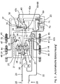
Fig. 1 ein Doppelkolben-Ventil für eine pneumatische Bremsanlage eines Anhängefahrzeugs in Fahrtstellung, -
Fig. 2 das Doppelkolben-Ventil in der Stellung für eine automatische Einbremsung, -
Fig. 3 das Doppelkolben-Ventil in der Stellung für einen Überlastschutz, -
Fig. 4 die pneumatische Bremsanlage eines Anhängefahrzeugs mit dem Doppelkolben-Ventil in Fahrtstellung, -
Fig. 5 die pneumatische Bremsanlage mit dem Doppelkolben-Ventil in der Stellung für eine automatische Einbremsung, -
Fig. 6 die pneumatische Bremsanlage mit dem Doppelkolben-Ventil in Parkstellung, -
Fig. 7 die pneumatische Bremsanlage mit dem Doppelkolben-Ventil in der Stellung für einen Überlastschutz, -
Fig. 8 die pneumatische Bremsanlage mit einem Select-High-Ventil in Fahrtstellung, -
Fig. 9 die pneumatische Bremsanlage mit dem Select-High-Ventil in der Stellung für eine automatische Einbremsung, -
Fig. 10 die pneumatische Bremsanlage mit Select-High-Ventil in Parkstellung, -
Fig. 11 die pneumatische Bremsanlage mit dem Select-High-Ventil in der Stellung für einen Überlastschutz, -
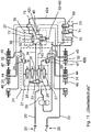
Fig. 12 die pneumatische Bremsanlage mit dem Doppelkolben-Ventil und einem eingeschalteten Blockierschutz, -
Fig. 13 die pneumatische Bremsanlage des Anhängefahrzeugs in teilweise vereinfachter Darstellung und mit weiteren Details. - Es wird zunächst Bezug genommen auf
Fig. 4 mit der Darstellung einer pneumatischen Bremsanlage für ein Anhängefahrzeug. Eine Steuerdruckleitung 20 führt zu einem Anhängerbremsmodul 21. Eine Vorratsdruckleitung 22 führt zu einem Parklöseventil 23 und von diesem weiter über einen Vorratsbehälter 24 zum Anhängerbremsmodul 21. Entsprechend der gesetzlichen Vorschriften weist die Steuerdruckleitung 20 einen gelben Kupplungskopf 25 für einen Steueranschluss auf und die Vorratsdruckleitung 22 einen roten Kupplungskopf 26 für einen Versorgungsanschluss. - Das Anhängerbremsmodul 21 ist in bekannter Weise aufgebaut, nämlich je Fahrzeugseite mit zwei Magnetventilen 27, 28 und einem Relaisventil 29. Über die Magnetventile 27, 28 wird die Zufuhr des Steuerdrucks zu den Relaisventilen 29 geregelt. Letztere sind über eine Leitung 30 mit Verzweigungen zugleich an Vorratsbehälterdruck aus dem Vorratsbehälter 24 angeschlossen und geben ausgesteuerten Betriebsbremsdruck an Betriebsbremszylinder 31, 32 ab.
- Weiterer Bestandteil des Anhängerbremsmoduls 21 ist ein Redundanzventil 33 als Magnetventil, mit dem die Verbindung zwischen der Steuerdruckleitung 20 und einer Leitung 34 trennbar und umstellbar ist. Auf diese Weise kann die Leitung 34 alternativ mit der Leitung 30 und dem Vorratsbehälterdruck aus dem Vorratsbehälter 24 verbunden werden. Die Leitung 34 verbindet außerdem über einen Abzweig 35 die Magnetventile 28 beider Fahrzeugseiten miteinander.
- Weiterhin verbindet die Leitung 34 (bei entsprechend geschaltetem Redundanzventil 33) die Steuerdruckleitung 20 mit einem ersten Steuereingang 36 einer Ventilanordnung 37. Die Ventilanordnung 37 hat insbesondere die Funktion eines Überlastschutzes und weist hierzu noch einen zweiten Steuereingang 38 sowie einen ersten Anschluss 39, einen zweiten Anschluss 40 und einen dritten Anschluss 41 auf, siehe auch
Fig. 1 bis 3 . - Der zweite Steuereingang 38 ist über eine Leitung 42a und das Parklöseventil 23 an die Vorratsdruckleitung 22 angeschlossen. Der erste Anschluss 39 ist über eine Leitung 42b, ein Rückschlagventil 43 und das Anhängerbremsmodul 21 mit dem Vorratsbehälter 24 verbunden. Der zweite Anschluss 40 ist über eine Leitung 42c und Verzweigungen mit Federspeicher-Bremszylindern 44, 45 beider Fahrzeugseiten verbunden. Der dritte Anschluss 41 ist ein Entlüftungsanschluss.
- In der gezeigten Bremsanlage sind die Betriebsbremszylinder 31, 32 Bestandteile sogenannter Kombizylinder, nämlich mit integrierten Federspeicher-Bremszylindern 44, 45, wobei die Kräfte beim Betätigen der Betriebsbremse einerseits und von Federspeichern andererseits auf denselben Bremskolben 46, 47 wirken.
- Die Ventilanordnung 37 beinhaltet eine Ventileinheit 48 nach Art eines Doppelkolben-Ventils, siehe
Fig. 1-3 , hier mit einem Gehäuse 49, in dem zum Steuern der Ventilfunktionen zwei Kolben 50, 51 koaxial bewegbar sind. In einem oberen, ersten Zylinderraum 52 ist der erste Kolben 50 durch über den Steuereingang 36 zugeführten Steuerdruck abwärts in Richtung auf den zweiten Kolben 51 bewegbar. Dabei weist der erste Kolben 50 einen abwärtsgerichteten Fortsatz 53 mit verringertem Durchmesser auf, so dass um den Fortsatz 53 und darunter ein zweiter Zylinderraum 54 gebildet ist. Der zweite Steuereingang 38 führt in den zweiten Zylinderraum 54 zwischen den beiden Kolben 50, 51. Durch den Fortsatz 53 weisen die beiden Kolben 50, 51 stets einen Mindestabstand zueinander auf, so dass der zweite Steuereingang 38 durch die Kolben 50, 51 nicht verschließbar ist. - Der zweite Kolben 51 ist gestuft ausgebildet, mit einem breiten Kopf 55 mit Dichtung 56 und einem schmaleren Fortsatz 57 mit Dichtung 58. Der Kopf 55 liegt randseitig an einer Druckfeder 59 an, die den zweiten Kolben 51 in Richtung auf den ersten Kolben 50 drückt.
- Der Fortsatz 57 des zweiten Kolbens 51 ist hohl und nach unten mit einer Öffnung 60 sowie nahe dem Kopf 55 auch seitlich mit einer Öffnung 61 versehen. Die beiden Öffnungen 60, 61 sind au ßenseitig durch die Dichtung 58 gegeneinander abgeschlossen bzw. voneinander getrennt. Im Bereich der Öffnung 61 ist um den Fortsatz 57 herum ein Ringraum 61a gebildet, welcher zusätzlich zur Öffnung 61 noch den dritten Anschluss 41 als Öffnung aufweist und im Übrigen durch die Dichtungen 56, 58 abgeschlossen ist.
- Das Gehäuse 49 weist in seinem unteren Bereich einen breiteren untersten, ringförmigen Zylinderraum 62 und darüber einen etwas schmaleren, ringförmigen Zylinderraum 63 auf. Der zweite Anschluss 40 ist zugleich eine Öffnung des Zylinderraums 63 und der erste Anschluss 39 ist eine Öffnung des Zylinderraums 62.
- An einem Übergang zwischen den beiden Zylinderräumen 62, 63 ist eine innen umlaufende Kante 64 gebildet, gegen die ein im untersten Zylinderraum 62 gehaltener Hilfskolben 65 mittels einer Druckfeder 66 aufwärts drückt. Die Druckfeder 66 ist relativ schwach ausgebildet und bewirkt lediglich, dass der Hilfskolben 65, sofern nicht weitere Kräfte wirken, an der umlaufenden Kante 64 anliegt und dort den untersten Zylinderraum 62 abschließt. Der Hilfskolben 65 ist vorzugsweise an beiden axialen Enden offen und innenseitig auf einer Dichtung 67 geführt.
- Der erste Kolben 50 weist außenseitig eine umlaufende Dichtung 68 auf. Der Fortsatz 57 des zweiten Kolbens 51 ist im Zylinderraum 63 mit der au ßenseitigen Dichtung 58 geführt.
- Die Richtungsangaben "oben" und "unten" beziehen sich auf die Ausrichtung der Ventileinheit 48 in den Figuren. In der Praxis kann die Ventileinheit 48 eine andere Lage einnehmen, so dass die Richtungsangaben anzupassen sind. Die Ventileinheit 48 ist hier als 3/2-Wegeventil ausgeführt, mit einer oberen Schaltstellung in den
Figuren 2 ,5 ,6 und einer unteren Schaltstellung in denFig. 1 ,3 ,4 ,7 . Durch die Konstruktion der Ventileinheit 48 sind die Funktionen der inFig. 4 sichtbaren Ventilanordnung 37 in einem Gehäuse (im Gehäuse 49) vereint. Nachfolgend werden die Funktionen der Ventilanordnung 37 anhand derFig. 4 - 7 erläutert:
In Fahrtstellung gemäßFig. 4 ist die pneumatische Bremsanlage in Bereitschaft. Das heißt, die Federspeicher-Bremszylinder 44, 45 sind durch Vorratsbehälterdruck aus dem Vorratsbehälter 24 belüftet. Hierzu ist der erste Anschluss 39 mit dem zweiten Anschluss 40 über die Ventilanordnung 37 verbunden. Die Ventilanordnung 37 befindet sich in einer aktiv geschalteten, zweiten Schaltstellung. Ausgelöst ist diese zweite Schaltstellung durch den am zweiten Steuereingang 38 anliegenden Vorratsdruck von mindestens 2,5 bar auf der Vorratsdruckleitung 22. Der Vorratsdruck wird hierzu von der Vorratsdruckleitung 22 durch das Parklöseventil 23 und durch die Leitung 42a bis zum zweiten Steuereingang 38 geführt. Der dort anliegende Vorratsdruck beaufschlagt den zweiten Kolben 51, so dass die Ventileinheit 48 die Fahrtstellung gemäßFig. 1 einnimmt. Dabei liegt am ersten Steuereingang 36 kein Druck an, der erste Kolben 50 wird nicht beaufschlagt und befindet sich in seiner oberen Stellung. Da außerdem kein Steuerdruck aus der Steuerdruck-Leitung 20 anliegt, sind auch die Bremszylinder 30, 31, 32 unbelüftet. -
Fig. 5 zeigt die Bestandteile der pneumatischen Bremsanlage nach einer automatischen Einbremsung des Anhängefahrzeugs durch Verlust des Vorratsdrucks in der Vorratsdruckleitung 22, etwa durch Abriss des roten Kupplungskopfes 26. - Drucklos ist dann auch der zweite Steuereingang 38, ebenso der erste Steuereingang 36 ohne Betätigung der Betriebsbremsen. Entsprechend sind beide Zylinderräume 52, 54 entlüftet und beide Kolben 50, 51 durch Druck der Feder 59 nach oben bewegt, siehe auch
Fig. 2 . Im Gegensatz zuFig. 4 befindet sich inFig. 5 die Ventilanordnung 37 in einer oberen Schaltstellung. Der erste Anschluss 39 ist abgesperrt. Der zweite Anschluss 40 ist zur Entlüftung der Federspeicher-Bremszylinder 44, 45 mit dem dritten Anschluss 41 verbunden. Die Federspeicher-Bremszylinder 44, 45 sind entlüftet und das Anhängefahrzeug wird abgebremst oder ist eingebremst. Die Betriebsbremsen sind inaktiv. - In
Fig. 6 ist eine Parkstellung der pneumatischen Bremsanlage gezeigt. Die Ventilanordnung 37 nimmt dieselbe Schaltstellung ein wie inFig. 5 beim automatischen Einbremsen nach Verlust des Vorratsdrucks in der Vorratsdruckleitung 22. InFig. 6 kann der Vorratsdruck jedoch weiterhin in der Vorratsdruckleitung 22 vorhanden sein. Der Druckverlust am zweiten Steuereingang 38 wird stattdessen erzielt durch Umschaltung des Parklöseventils 23. Dieses beinhaltet zumindest zwei Ventile, nämlich ein Parkventil 69 und ein Löseventil 70. Das Löseventil 70 befindet sich in allen hier dargestellten Zuständen in der gleichen Schaltposition. Demgegenüber befindet sich das Parkventil 69 in denFig. 4 und5 in einer Fahrtstellung und nur inFig. 6 in einer Parkstellung. Dadurch ist der zweite Steuereingang 38 mit einer Entlüftung 71 am Parkventil 69 verbunden und somit drucklos. Die Betriebsbremse ist inaktiv. Der erste Steuereingang 36 ist ebenfalls drucklos. Die Zylinderräume 52, 54 sind entlüftet. Die Ventilanordnung nimmt dieselbe Stellung ein wie beim automatischen Einbremsen inFig. 5 . Dadurch ist der zweite Anschluss 40 mit dem dritten Anschluss 41 zur Entlüftung der Federspeicher-Bremszylinder verbunden. Das Fahrzeug ist gebremst. - In
Fig. 7 ist die Funktion der Ventilanordnung 37 als Überlastschutz erkennbar. Vermieden werden soll eine Doppelbelastung innerhalb der Betriebsbremszylinder 30, 31 und 32 durch Betätigung der Betriebsbremse einerseits und durch die Kraft der entlüfteten Federspeicher-Bremszylinder 44, 45 andererseits. Ausgegangen wird von der Parkstellung gemäßFig. 6 mit geschaltetem Parkventil 69. GemäßFig. 7 liegt zusätzlich Steuerdruck in der Steuerdruck-Leitung 20 an. Dieser regelt über die Magnetventile 27, 28 und Relaisventile 29 die Zufuhr des Vorratsbehälterdrucks aus dem Vorratsbehälter 24 zu den Betriebsbremszylindern 31, 32. Je mehr Steuerdruck eingesteuert wird, umso höher sind die zusätzlichen mechanischen Kräfte innerhalb der Betriebsbremszylinder 31, 32. Da die Federspeicher-Bremszylinder 44, 45 bereits entlüftet sind, können die Kräfte insgesamt zu stark werden. Der Steuerdruck wird außerdem über den ersten Steuereingang 36 in den Zylinderraum 52 geführt, sieheFig. 3 . Je nach Härte und Kennlinie der Druckfeder 59 (und der Druckfeder 66) schaltet die Ventilanordnung 37 aus der Parkstellung gemäßFig. 5 in die Stellung gemäßFig. 7 . Dadurch wird der erste Anschluss 39 mit dem zweiten Anschluss 40 verbunden und die Federspeicher-Bremszylinder 44, 45 werden mit Druck aus dem Vorratsbehälter 24 belüftet. Im Ergebnis sind nur noch die Betriebsbremsen wirksam. Sobald der Steuerdruck wieder nachlässt, schaltet die Ventilanordnung 37 in die Stellung gemäßFig. 6 zurück und die Federspeicher-Bremszylinder 44,45 werden wieder entlüftet. - Bei dem anhand der
Fig. 7 dargestellten Überlastschutz erfolgt die Belüftung und Entlüftung der Federspeicher-Bremszylinder 44, 45 nicht proportional zur Veränderung des Steuerdrucks. Vielmehr werden die Federspeicher-Bremszylinder 44, 45 in Abhängigkeit von der Überschreitung oder Unterschreitung eines Steuerdruck-Grenzwerts entlüftet oder belüftet. Der Grenzwert beträgt hier 2,5 bar oder mehr. Der Überlastschutz ist auch wirksam ausgehend vom inFig. 5 (automatische Einbremsung) gezeigten Zustand. - Die
Fig. 8 - 11 beziehen sich wie dieFig. 4 - 7 auf die verschiedenen Zustände Fahrtstellung (Fig. 8 ), automatische Einbremsung (Fig. 9 ), Parkstellung (Fig. 10 ) und Überlastschutz (Fig. 11 ). Im Unterschied zu denFig. 4 - 7 ist die Ventilanordnung 37 in anderer Weise ausgebildet, nämlich nicht mit einem Doppelkolben-Ventil, sondern mit einem zusätzlichen Select-High-Ventil 72 zur Steuerung der beiden Zustände der Ventilanordnung 37 und der Verbindung der Anschlüsse 39, 40, 41. Das Select-High-Ventil 72 lässt den höheren der an den beiden Steuereingängen 36, 38 anliegenden Druck zu einem dritten Steuereingang 73 durch. In Abhängigkeit von dem hier anliegenden Druck nimmt die Ventilanordnung 37 die zugehörige Schaltstellung ein. Eine Umsetzung in die Praxis ist möglich als 3/2-Wegeventil und durch Abwandlung der Ventileinheit 48 in denFig. 1 - 3 . Der erste Kolben 50 entfällt, der Steuereingang 38 bleibt geschlossen und der Steuereingang 36 wird ersetzt durch den dritten Steuereingang 73. Dieser wird gespeist aus dem Select-High-Ventil 72. - Das Select-High-Ventil 72 enthält zwischen den Steuereingängen 36, 38 eine Rückschlagfunktion, so dass der jeweils anliegende höhere Druck nur in den Steuereingang 73 gelangen und nicht über den Steuereingang mit dem niedrigeren Druck entweichen kann. Das Vorzeichen der Druckdifferenz an den Steuereingängen 36, 38 ist in den
Fig. 8 - 11 anhand der Position einer Kugel 74 erkennbar. InFig. 8 (Fahrtstellung) liegt am Steuereingang 38 Vorratsdruck an, während am Steuereingang 36 ein geringerer oder kein Steuerdruck anliegt. InFig. 9 (automatische Einbremsung) wird der Steuereingang 38 aus der Fahrtstellung heraus durch Abriss der Vorratsdruckleitung 22 drucklos, während der Steuereingang 36 ohnehin drucklos ist. Die Kugel 74 bleibt vor dem Steuereingang 36, bis auch am Steuereingang 38 kein Druck mehr anliegt. - In
Fig. 10 (Parkstellung) ist ebenfalls die Fahrtstellung gemäßFig. 8 Ausgangspunkt der Überlegungen. In Fahrtstellung liegt am Steuereingang 38 der volle Vorratsdruck an (wie inFig. 8 ). Das Fahrzeug wird mittels der Betriebsbremsen durch Regelung des Steuerdrucks gebremst. In Parkstellung werden die Betriebsbremsen grundsätzlich nicht betätigt, d. h. am Steuereingang 36 liegt kein Druck mehr an und zugleich ist der Steuereingang 38 über das Parkventil 69 entlüftet. Bis zur endgültigen Entlüftung des Steuereingangs 38 bleibt die Kugel 74 in der Position gemäßFig. 10 , also links. Die Federspeicher-Bremszylinder 44,45 sind entlüftet, die Federspeicherbremsen halten das Anhängefahrzeug. - Ausgehend von der Parkstellung gemäß
Fig. 10 ergibt sich die Stellung gemäßFig. 11 (Überlastschutz) bei Betätigung der Betriebsbremse während der Parkstellung. Es ist dann am Steuereingang 36 Steuerdruck wirksam. Die Kugel 74 wandert in die rechte Position gemäßFig. 11 und der Steuerdruck gelangt in den Steuereingang 73 zum Umschalten der Ventilanordnung 37. - Der Überlastschutz wurde bisher nur ausgehend von der Parkstellung gemäß den
Fig. 6 und10 erläutert. Ein Überlastschutz besteht auch ausgehend von einer automatischen Einbremsung (Fig. 5 und9 ). Wenn nämlich nach automatischer Einbremsung die Betriebsbremse betätigt wird, gelangt Steuerdruck zum ersten Steuereingang 36. Der zweite Steuereingang 38 kann dabei drucklos bleiben. Die Ventilanordnung 37 schaltet um in die in denFig. 7 und11 gezeigte Stellung mit Belüftung der Federspeicher-Bremszylinder 44, 45. - Eine weitere Besonderheit zeigt
Fig. 12 . Ausgegangen wird von einer automatischen Einbremsung (Fig. 5 und9 ). Der zweite Steuereingang 38 ist drucklos durch Abriss der Vorratsdruckleitung 22. Das Anhängefahrzeug wird durch die Federspeicher-Bremszylinder 44, 45 stark abgebremst. Die Räder können blockieren. Die üblicherweise vorhandene Antiblockierregelung für die Betriebsbremse ist nicht wirksam. Um nun eine Antiblockierregelung über das Anhängerbremsmodul 21 zu ermöglichen, schaltet das Redundanzventil 33 aus der Position derFig. 4 -11 in die Position gemäßFig. 12 . Dadurch gelangt nicht mehr der Steuerdruck über das Redundanzventil 33 zum ersten Steuereingang 36, sondern über die Leitung 30 Vorratsbehälterdruck aus dem Vorratsbehälter 24. Entsprechend schaltet die Ventilanordnung 37 in die Stellung gemäßFig. 12 , so dass der Vorratsbehälterdruck auch zum zweiten Anschluss 40 gelangt und die Federspeicher-Bremszylinder 44, 45 belüften kann. Das Anhängefahrzeug kann nun über die eigenen Betriebsbremsen (Betriebsbremszylinder 31, 32) mit Vorratsbehälterdruck aus dem Vorratsbehälter 24 eingebremst werden. Dabei ist die im Anhängerbremsmodul 21 üblicherweise vorhandene Antiblockierregelung wirksam. - Der pneumatischen Bremsanlage ist ein elektronisches Bremssystem zugeordnet. Bestandteil des elektronischen Bremssystems ist ein Bremsensteuergerät, welches hier nicht gezeigt ist und welches in das Anhängerbremsmodul 21 integriert ist oder zusätzlich vorhanden sein kann. Das Bremsensteuergerät erhält Zustandsinformationen in an sich bekannter Weise über Sensoren an der pneumatischen Bremsanlage und steuert die Funktionen des Anhängerbremsmoduls 21. Beispielsweise werden Steuerdruck und Vorratsdruck überwacht, hier vorzugsweise auch die Stellung der Ventilanordnung 37. Bei plötzlichem Verlust des Drucks in der Vorratsdruckleitung 22 und ausreichendem Druck im Vorratsbehälter 24 kann das Bremsensteuergerät das Redundanzventil 33 umschalten in die Position gemäß
Fig. 12 und zugleich eine Notbremsung mit Blockierschutz über das Anhängerbremsmodul 21 mit Regelung der Ventile 27, 28 veranlassen. Nur wenn der Vorratsbehälter 24 nicht mehr ausreichenden Druck aufweist, wird das Redundanzventil 33 nicht zum Umschalten angesteuert, so dass eine automatische Bremsung durch die Federspeicher-Bremszylinder 44, 45 stattfindet. - An das Bremsensteuergerät im Anhängerbremsmodul 21 ist über eine Leitung 75 ein Längsverzögerungssensor 76 angeschlossen. Dessen Signale werden im Bremsensteuergerät verarbeitet. Vorzugsweise schaltet das Redundanzventil 33 nur in die Position gemäß
Fig. 12 um, wenn die Längsverzögerung einen Grenzwert überschreitet. Der Längsverzögerungssensor 76 kann auch in das Bremsensteuergerät bzw. in das Anhängerbremsmodul 21 integriert sein. - In
Fig. 13 sind die in den übrigen Figuren sichtbaren Details des Anhängerbremsmoduls 21, der Ventilanordnung 37 und des Parklöseventils 23 nicht eingezeichnet. Stattdessen sind andere Details der pneumatischen Bremsanlage des Anhängefahrzeugs sichtbar:
Drei nicht näher gezeigte Achsen tragen je zwei Räder 77, 78, 79. Den Rädern 78, 79 der beiden hinteren Achsen sind jeweils Drehzahlsensoren 80, 81 zugeordnet. Deren Signale werden über Signalleitungen 82 dem Anhängerbremsmodul 21 zugeführt und im dort integrierten Steuergerät verarbeitet. - Anhängefahrzeug und Zugfahrzeug sind über eine elektrische Leitung miteinander verbunden. Hierzu ist parallel zu den Kupplungsköpfen 25, 26 eine elektrische Schnittstelle 83 vorgesehen. Von dieser führt eine elektrische Leitung 84 zum Anhängerbremsmodul 21. Integriert in die elektrische Leitung 84 ist eine elektrische Bremsleitung nach ISO-11992, mit der ein Bremswunsch des Fahrers vom Zugfahrzeug zum Anhängefahrzeug übermittelt wird.
- Das Steuergerät im Anhängerbremsmodul 21 ermittelt aufgrund der über die elektrische Bremsleitung übersandten Signale einerseits und die Signale der Raddrehzahlsensoren 80, 81 einerseits, ob ein Bremswunsch vorliegt und/oder mindestens ein Rad bei Fahrt des Anhängefahrzeugs blockiert. Wenn kein Bremswunsch vorliegt und mindestens ein Rad bei Fahrt blockiert, regelt das Steuergerät die pneumatische Bremsanlage derart, dass die Federspeicher-Bremszylinder 44, 45 belüftet werden und automatisch die Betriebsbremsen mit Antiblockierregelung zur Ausführung einer Vollbremsung aktiviert werden. Da das Steuergerät die Bremsung ausführt und der Fahrer nicht beteiligt ist, kann die Bremsung auch nach einem im Steuergerät hinterlegten Programm mit geringerer Bremskraft als bei einer Vollbremsung ausgeführt werden.
Claims (7)
- Verfahren zum Regeln von Bremsen in einem Anhängefahrzeug mit pneumatischer Bremsanlage, Betriebsbremsen und elektronischem Bremssystem mit Antiblockier-Regelung,
wobei mindestens eine Achse des Anhängefahrzeugs mit Federspeicher-Bremsen und Drehzahlsensoren bestückt ist, und wobei die pneumatische Bremsanlage insbesondere einen Vorratsbehälter (24) mit Vorratsbehälterdruck aufweist, wobeia) das elektronische Bremssystem überwacht, ob ein Bremswunsch vorliegt,b) das elektronische Bremssystem überwacht, ob mindestens ein Rad (78, 79) der mindestens einen Achse blockiert,c) wenn kein Bremswunsch vorliegt und mindestens ein Rad (78, 79) der mindestens einen Achse bei Fahrt blockiert, regelt das elektronische Bremssystem die pneumatische Bremsanlage derart, dass die Federspeicher-Bremsen belüftet werden und das Anhängefahrzeug durch die Betriebsbremsen automatisch und mit Antiblockierregelung gebremst wird, dadurch gekennzeichnet, dass eine pneumatisch angesteuerte Ventileinheit (48) die Federspeicher-Bremsen mit dem Vorratsbehälterdruck belüftet, wenn an einem Steuereingang der Ventileinheit (48) ein Steuerdruck oberhalb eines Grenzwerts anliegt, und dass zum Auslösen der Belüftung der Federspeicher-Bremsen dem Steuereingang der Ventileinheit (48) der Vorratsbehälterdruck zugeführt wird. - Verfahren nach Anspruch 1, dadurch gekennzeichnet, dass ein Bremswunsch vorliegt, wenn in einer pneumatischen Steuerdruckleitung (22) im Anhängefahrzeug oder in einem Zugfahrzeug des Anhängefahrzeugs ein Druck oberhalb eines Grenzwerts gemessen wird oder wenn auf einer elektrischen Bremsleitung ein Signal zur Betätigung der Betriebsbremse übermittelt wird.
- Verfahren nach Anspruch 1 oder 2, dadurch gekennzeichnet, dass das Anhängefahrzeug bis zum Stillstand abgebremst wird.
- Verfahren nach Anspruch 1 oder einem der weiteren Ansprüche, dadurch gekennzeichnet, dass eine Längsverzögerung des Anhängefahrzeugs überwacht wird und dass nur dann das Anhängefahrzeug automatisch gebremst wird und die Federspeicher-Bremsen belüftet werden, wenn die Längsverzögerung einen Grenzwert überschreitet.
- Ventilanordnung (37) für eine pneumatische Bremsanlage eines Anhängefahrzeugs, insbesondere in Verbindung mit einem elektronischen Bremssystem, wobei die pneumatische Bremsanlage einen Vorratsbehälter (24) mit Vorratsbehälterdruck aufweist,
mit einer pneumatisch angesteuerten Ventileinheit (48) zum Belüften von Federspeicherbremsen mit Vorratsbehälterdruck, sofern an einem Steuereingang (36) der Ventileinheit (48) ein Druck oberhalb eines Grenzwerts anliegt, und mit einem Magnetventil (33), welches einerseits an einen Steuerdruck der pneumatischen Bremsanlage und an den Vorratsbehälterdruck angeschlossen und zwischen Steuerdruck und Vorratsbehälterdruck umschaltbar ist, und welches andererseits mit dem Steuereingang (36) der Ventileinheit (48) verbunden ist, so dass am Steuereingang (36) der Ventileinheit (48), je nach Stellung des Magnetventils, Steuerdruck oder Vorratsbehälterdruck anliegen. - Anhängefahrzeug mit pneumatischer Bremsanlage, elektronischem Bremssystem und einer Ventilanordnung (37) nach Anspruch 5.
- Elektronisches Steuergerät zur Durchführung des Verfahrens nach einem der Ansprüche 1 bis 4, zur Steuerung einer Ventilanordnung (37) nach Anspruch 5 und/oder für ein Anhängefahrzeug nach Anspruch 6.
Applications Claiming Priority (2)
| Application Number | Priority Date | Filing Date | Title |
|---|---|---|---|
| DE102015007384.2A DE102015007384A1 (de) | 2015-06-10 | 2015-06-10 | Verfahren zum Regeln von Bremsen in einem Anhängefahrzeug |
| PCT/EP2016/000920 WO2016198152A1 (de) | 2015-06-10 | 2016-06-04 | Verfahren zum regeln von bremsen in einem anhängefahrzeug |
Publications (3)
| Publication Number | Publication Date |
|---|---|
| EP3307595A1 EP3307595A1 (de) | 2018-04-18 |
| EP3307595B1 true EP3307595B1 (de) | 2021-03-17 |
| EP3307595B8 EP3307595B8 (de) | 2021-06-02 |
Family
ID=56132880
Family Applications (1)
| Application Number | Title | Priority Date | Filing Date |
|---|---|---|---|
| EP16729489.1A Active EP3307595B8 (de) | 2015-06-10 | 2016-06-04 | Verfahren zum regeln von bremsen in einem anhängefahrzeug |
Country Status (5)
| Country | Link |
|---|---|
| US (1) | US10717423B2 (de) |
| EP (1) | EP3307595B8 (de) |
| CN (1) | CN107531222B (de) |
| DE (1) | DE102015007384A1 (de) |
| WO (1) | WO2016198152A1 (de) |
Families Citing this family (9)
| Publication number | Priority date | Publication date | Assignee | Title |
|---|---|---|---|---|
| DE102015007383A1 (de) * | 2015-06-10 | 2016-12-15 | Wabco Gmbh | Pneumatische Bremsanlage für ein Anhängefahrzeug |
| DE102016010639A1 (de) | 2016-09-02 | 2018-03-08 | Wabco Gmbh | Pneumatische Bremsanlage für ein Anhängerfahrzeug |
| US20180201144A1 (en) * | 2017-01-13 | 2018-07-19 | NextEv USA, Inc. | Authentication using electromagnet signal detection |
| DE102018108005A1 (de) | 2018-04-05 | 2019-10-10 | Knorr-Bremse Systeme für Nutzfahrzeuge GmbH | Steuereinrichtung für eine Parkbremseinrichtung eines Fahrzeugs |
| US10780872B2 (en) * | 2018-04-17 | 2020-09-22 | Bendix Commercial Vehicle Systems Llc | Apparatus and method for trailer service brake control |
| CN116215476A (zh) * | 2023-03-31 | 2023-06-06 | 北京福田戴姆勒汽车有限公司 | 车辆防抱死制动系统及其控制方法和车辆 |
| DE102023120278A1 (de) | 2023-07-31 | 2025-02-06 | Zf Cv Systems Global Gmbh | Verfahren zur Prüfung eines pneumatischen Bremssystems, Bremssystem, Steuermodul und Fahrzeug |
| GB202413708D0 (en) * | 2024-09-17 | 2024-10-30 | Knorr Bremse Ag | Trailer braking system |
| DE102025103493A1 (de) * | 2025-01-30 | 2026-07-30 | Zf Cv Systems Global Gmbh | Verfahren zur Erkennung einer selbsttätigen Federspeicherentlüftung, Fahrzeug, Steuereinheit und Computerprogramm |
Family Cites Families (20)
| Publication number | Priority date | Publication date | Assignee | Title |
|---|---|---|---|---|
| DE3544356A1 (de) * | 1985-12-14 | 1987-06-19 | Wabco Westinghouse Fahrzeug | Druckmittelbetaetigte bremsanlage |
| DE19942533A1 (de) | 1999-09-07 | 2000-11-30 | Daimler Chrysler Ag | Bremsvorrichtung für Fahrzeuge, insbesondere für druckluftgebremste Nutzfahrzeuge |
| EP1188634B2 (de) * | 2000-09-14 | 2011-12-21 | WABCO GmbH | Anhängerbremsventil für Anhängefahrzeuge mit elektronischer Bremsregelung und erweiterter Sicherheit des geparkten Anhängers |
| US7784879B2 (en) * | 2002-07-16 | 2010-08-31 | Haldex Brake Corporation | Electronic control air management with parking brake and trailer supply control |
| DE10233018A1 (de) * | 2002-07-20 | 2004-01-29 | Iveco Magirus Ag | Verfahren und Bremsvorrichtung zur Feststell-Bremsung von Fahrzeugen , insbesondere Lastkraftwagen |
| DE10356672B4 (de) | 2003-12-04 | 2006-10-19 | Knorr-Bremse Systeme für Nutzfahrzeuge GmbH | Bremsanlage in einem Fahrzeug |
| US7971942B2 (en) * | 2006-09-19 | 2011-07-05 | Wabco Gmbh | Trailer brake system |
| DE102007021646A1 (de) * | 2007-05-09 | 2008-11-13 | Wabco Gmbh | Modulator |
| DE102007053764B4 (de) * | 2007-11-12 | 2009-08-20 | Haldex Brake Products Gmbh | Bremsanlage für einen Anhänger eines Kraftfahrzeuges |
| DE102008009882A1 (de) | 2008-02-19 | 2009-08-20 | Wabco Gmbh | Feststellbremse für ein Fahrzeug und Verfahren zum Betrieb der Feststellbremse |
| DE102009031851B4 (de) | 2009-07-03 | 2021-02-11 | Dipl. Ing. Tietjen Gmbh | Verfahren zur Abbremsung einer Zugfahrzeug-Anhänger-Kombination und Einrichtung |
| DE102009031785A1 (de) * | 2009-07-06 | 2011-01-13 | Wabco Gmbh | Pneumatische Bremsanlage für ein Anhängefahrzeug und Bremssteuermodulator |
| GB2490925B (en) * | 2011-05-18 | 2017-05-10 | Haldex Brake Prod Ab | Vehicle braking system |
| GB2492124B (en) * | 2011-06-22 | 2017-08-09 | Haldex Brake Prod Ab | Vehicle braking system |
| DE102012101871B4 (de) * | 2012-03-06 | 2013-12-12 | Haldex Brake Products Gmbh | Parkbremsventileinrichtung und pneumatische Anhänger-Druckluftbremsanlage |
| CN202541518U (zh) * | 2012-04-26 | 2012-11-21 | 青岛四方车辆研究所有限公司 | 城轨车辆停放制动控制单元的强迫缓解阀 |
| DE102013100538B4 (de) * | 2013-01-18 | 2016-06-02 | Haldex Brake Products Gmbh | Druckluftanlage eines Anhängers eines Nutzfahrzeugs |
| DE102013106260B4 (de) * | 2013-06-17 | 2022-05-25 | Haldex Brake Products Aktiebolag | Elektropneumatische Bremsanlage |
| DE102013017875A1 (de) * | 2013-10-26 | 2015-05-21 | Wabco Gmbh | Relaisventil, Ventileinrichtung sowie Fahrzeug damit |
| CN104149769B (zh) * | 2014-08-05 | 2016-09-28 | 常州南车铁马科技实业有限公司 | 轨道车辆基础制动装置的防叠加阀 |
-
2015
- 2015-06-10 DE DE102015007384.2A patent/DE102015007384A1/de not_active Withdrawn
-
2016
- 2016-06-04 EP EP16729489.1A patent/EP3307595B8/de active Active
- 2016-06-04 WO PCT/EP2016/000920 patent/WO2016198152A1/de not_active Ceased
- 2016-06-04 US US15/580,807 patent/US10717423B2/en active Active
- 2016-06-04 CN CN201680025370.8A patent/CN107531222B/zh active Active
Non-Patent Citations (1)
| Title |
|---|
| None * |
Also Published As
| Publication number | Publication date |
|---|---|
| EP3307595B8 (de) | 2021-06-02 |
| US10717423B2 (en) | 2020-07-21 |
| EP3307595A1 (de) | 2018-04-18 |
| DE102015007384A1 (de) | 2016-12-15 |
| CN107531222B (zh) | 2021-06-08 |
| US20180222463A1 (en) | 2018-08-09 |
| WO2016198152A1 (de) | 2016-12-15 |
| CN107531222A (zh) | 2018-01-02 |
Similar Documents
| Publication | Publication Date | Title |
|---|---|---|
| EP3600991B1 (de) | Elektro-pneumatische handbremse (eph) mit integrierten tcv (skandinavische ansteuerung) | |
| EP2567874B1 (de) | Ventilbaugruppe für eine Anhängerbremsanlage | |
| DE102007038472B4 (de) | Ventilanordnung zur Steuerung einer Bremsanlage eines Anhängerfahrzeugs | |
| EP3247596B2 (de) | Elektronisches bremssystem für eine druckluftbremsanlage eines nutzfahrzeugs | |
| WO2016198152A1 (de) | Verfahren zum regeln von bremsen in einem anhängefahrzeug | |
| EP2650183B1 (de) | Parkbremsventileinrichtung und pneumatische Anhänger-Druckluftbremsanlage | |
| DE102017006356A1 (de) | Elektro-Pneumatische Handbremse (EPH) mit integriertem TCV (Europäische Ansteuerung) | |
| EP3307594B2 (de) | Pneumatische bremsanlage für ein anhängefahrzeug | |
| EP2631131B1 (de) | Landwirtschaftliches Zugfahrzeug | |
| EP3112230A1 (de) | Feststellbremsmodul, bremsanlage und fahrzeug damit sowie verfahren zum betreiben einer feststellbremseinrichtung mit einem solchen modul | |
| EP3190014B1 (de) | Bremsanlage eines traktors | |
| DE102013007881A1 (de) | Verfahren zur Abbremsung einer Zugfahrzeug-Anhängerkombination mit reduzierter Anhängerbremskraft abhängig vom Ansprechen des Zugfahrzeug-ABS | |
| EP2426021A1 (de) | Parkventil für einen Nutzfahrzeug-Anhänger | |
| DE102022114280A1 (de) | Verfahren und Vorrichtung zum sicheren Bremsen eines Anhängers | |
| EP4366994B1 (de) | Elektropneumatische ventilanordnung mit selbsthaltendem sicherheitsventil | |
| EP2082935B1 (de) | Bremseinrichtung eines wenigstens zweiachsigen, eine gelenkte Vorderachse aufweisenden Anhängerfahrzeugs einer Zugfahrzeug-Anhängerkombination | |
| EP3507148B1 (de) | Pneumatische bremsanlage für ein anhängefahrzeug | |
| EP3724044A1 (de) | Pneumatische ventilanordnung für ein anhängefahrzeug | |
| EP2239172B1 (de) | Verfahren zum Betreiben einer Bremseinrichtung eines Haltestellen anfahrenden Kraftfahrzeugs | |
| DE102014116732B4 (de) | Bremseinrichtung eines Fahrzeugs mit elektrischer und durch eine pneumatische Notzuspanneinrichtung zuspannbarer Feststellbremse sowie Fahrzeug mit einer solchen Bremseinrichtung | |
| EP4304904A1 (de) | Verfahren zum betreiben eines elektropneumatischen feststellbremssystems und elektropneumatisches feststellbremssystem | |
| DE102020106426A1 (de) | Achsmodulator eines Kraftfahrzeugs | |
| DE102023134202B3 (de) | Bremsanlage eines Fahrzeugs mit redundanter Parkbremsfunktion | |
| DE102019130761A1 (de) | Ventileinheit für eine pneumatische Bremsanlage eines Anhängefahrzeugs |
Legal Events
| Date | Code | Title | Description |
|---|---|---|---|
| STAA | Information on the status of an ep patent application or granted ep patent |
Free format text: STATUS: THE INTERNATIONAL PUBLICATION HAS BEEN MADE |
|
| PUAI | Public reference made under article 153(3) epc to a published international application that has entered the european phase |
Free format text: ORIGINAL CODE: 0009012 |
|
| STAA | Information on the status of an ep patent application or granted ep patent |
Free format text: STATUS: REQUEST FOR EXAMINATION WAS MADE |
|
| 17P | Request for examination filed |
Effective date: 20180110 |
|
| AK | Designated contracting states |
Kind code of ref document: A1 Designated state(s): AL AT BE BG CH CY CZ DE DK EE ES FI FR GB GR HR HU IE IS IT LI LT LU LV MC MK MT NL NO PL PT RO RS SE SI SK SM TR |
|
| AX | Request for extension of the european patent |
Extension state: BA ME |
|
| DAV | Request for validation of the european patent (deleted) | ||
| DAX | Request for extension of the european patent (deleted) | ||
| GRAP | Despatch of communication of intention to grant a patent |
Free format text: ORIGINAL CODE: EPIDOSNIGR1 |
|
| STAA | Information on the status of an ep patent application or granted ep patent |
Free format text: STATUS: GRANT OF PATENT IS INTENDED |
|
| GRAJ | Information related to disapproval of communication of intention to grant by the applicant or resumption of examination proceedings by the epo deleted |
Free format text: ORIGINAL CODE: EPIDOSDIGR1 |
|
| STAA | Information on the status of an ep patent application or granted ep patent |
Free format text: STATUS: REQUEST FOR EXAMINATION WAS MADE |
|
| INTG | Intention to grant announced |
Effective date: 20201120 |
|
| INTC | Intention to grant announced (deleted) | ||
| GRAP | Despatch of communication of intention to grant a patent |
Free format text: ORIGINAL CODE: EPIDOSNIGR1 |
|
| STAA | Information on the status of an ep patent application or granted ep patent |
Free format text: STATUS: GRANT OF PATENT IS INTENDED |
|
| INTG | Intention to grant announced |
Effective date: 20210114 |
|
| GRAS | Grant fee paid |
Free format text: ORIGINAL CODE: EPIDOSNIGR3 |
|
| GRAA | (expected) grant |
Free format text: ORIGINAL CODE: 0009210 |
|
| STAA | Information on the status of an ep patent application or granted ep patent |
Free format text: STATUS: THE PATENT HAS BEEN GRANTED |
|
| AK | Designated contracting states |
Kind code of ref document: B1 Designated state(s): AL AT BE BG CH CY CZ DE DK EE ES FI FR GB GR HR HU IE IS IT LI LT LU LV MC MK MT NL NO PL PT RO RS SE SI SK SM TR |
|
| REG | Reference to a national code |
Ref country code: GB Ref legal event code: FG4D Free format text: NOT ENGLISH |
|
| REG | Reference to a national code |
Ref country code: CH Ref legal event code: EP |
|
| REG | Reference to a national code |
Ref country code: DE Ref legal event code: R096 Ref document number: 502016012607 Country of ref document: DE |
|
| REG | Reference to a national code |
Ref country code: IE Ref legal event code: FG4D Free format text: LANGUAGE OF EP DOCUMENT: GERMAN |
|
| REG | Reference to a national code |
Ref country code: AT Ref legal event code: REF Ref document number: 1371965 Country of ref document: AT Kind code of ref document: T Effective date: 20210415 |
|
| REG | Reference to a national code |
Ref country code: DE Ref legal event code: R081 Ref document number: 502016012607 Country of ref document: DE Owner name: ZF CV SYSTEMS EUROPE BV, BE Free format text: FORMER OWNER: WABCO GMBH, 30453 HANNOVER, DE Ref country code: CH Ref legal event code: PK Free format text: BERICHTIGUNG B8 |
|
| RAP4 | Party data changed (patent owner data changed or rights of a patent transferred) |
Owner name: ZF CV SYSTEMS HANNOVER GMBH |
|
| REG | Reference to a national code |
Ref country code: LT Ref legal event code: MG9D |
|
| PG25 | Lapsed in a contracting state [announced via postgrant information from national office to epo] |
Ref country code: BG Free format text: LAPSE BECAUSE OF FAILURE TO SUBMIT A TRANSLATION OF THE DESCRIPTION OR TO PAY THE FEE WITHIN THE PRESCRIBED TIME-LIMIT Effective date: 20210617 Ref country code: GR Free format text: LAPSE BECAUSE OF FAILURE TO SUBMIT A TRANSLATION OF THE DESCRIPTION OR TO PAY THE FEE WITHIN THE PRESCRIBED TIME-LIMIT Effective date: 20210618 Ref country code: HR Free format text: LAPSE BECAUSE OF FAILURE TO SUBMIT A TRANSLATION OF THE DESCRIPTION OR TO PAY THE FEE WITHIN THE PRESCRIBED TIME-LIMIT Effective date: 20210317 Ref country code: FI Free format text: LAPSE BECAUSE OF FAILURE TO SUBMIT A TRANSLATION OF THE DESCRIPTION OR TO PAY THE FEE WITHIN THE PRESCRIBED TIME-LIMIT Effective date: 20210317 Ref country code: NO Free format text: LAPSE BECAUSE OF FAILURE TO SUBMIT A TRANSLATION OF THE DESCRIPTION OR TO PAY THE FEE WITHIN THE PRESCRIBED TIME-LIMIT Effective date: 20210617 |
|
| REG | Reference to a national code |
Ref country code: NL Ref legal event code: MP Effective date: 20210317 |
|
| PG25 | Lapsed in a contracting state [announced via postgrant information from national office to epo] |
Ref country code: SE Free format text: LAPSE BECAUSE OF FAILURE TO SUBMIT A TRANSLATION OF THE DESCRIPTION OR TO PAY THE FEE WITHIN THE PRESCRIBED TIME-LIMIT Effective date: 20210317 Ref country code: RS Free format text: LAPSE BECAUSE OF FAILURE TO SUBMIT A TRANSLATION OF THE DESCRIPTION OR TO PAY THE FEE WITHIN THE PRESCRIBED TIME-LIMIT Effective date: 20210317 Ref country code: LV Free format text: LAPSE BECAUSE OF FAILURE TO SUBMIT A TRANSLATION OF THE DESCRIPTION OR TO PAY THE FEE WITHIN THE PRESCRIBED TIME-LIMIT Effective date: 20210317 |
|
| PG25 | Lapsed in a contracting state [announced via postgrant information from national office to epo] |
Ref country code: NL Free format text: LAPSE BECAUSE OF FAILURE TO SUBMIT A TRANSLATION OF THE DESCRIPTION OR TO PAY THE FEE WITHIN THE PRESCRIBED TIME-LIMIT Effective date: 20210317 |
|
| PG25 | Lapsed in a contracting state [announced via postgrant information from national office to epo] |
Ref country code: EE Free format text: LAPSE BECAUSE OF FAILURE TO SUBMIT A TRANSLATION OF THE DESCRIPTION OR TO PAY THE FEE WITHIN THE PRESCRIBED TIME-LIMIT Effective date: 20210317 Ref country code: CZ Free format text: LAPSE BECAUSE OF FAILURE TO SUBMIT A TRANSLATION OF THE DESCRIPTION OR TO PAY THE FEE WITHIN THE PRESCRIBED TIME-LIMIT Effective date: 20210317 Ref country code: LT Free format text: LAPSE BECAUSE OF FAILURE TO SUBMIT A TRANSLATION OF THE DESCRIPTION OR TO PAY THE FEE WITHIN THE PRESCRIBED TIME-LIMIT Effective date: 20210317 Ref country code: SM Free format text: LAPSE BECAUSE OF FAILURE TO SUBMIT A TRANSLATION OF THE DESCRIPTION OR TO PAY THE FEE WITHIN THE PRESCRIBED TIME-LIMIT Effective date: 20210317 |
|
| PG25 | Lapsed in a contracting state [announced via postgrant information from national office to epo] |
Ref country code: IS Free format text: LAPSE BECAUSE OF FAILURE TO SUBMIT A TRANSLATION OF THE DESCRIPTION OR TO PAY THE FEE WITHIN THE PRESCRIBED TIME-LIMIT Effective date: 20210717 Ref country code: PL Free format text: LAPSE BECAUSE OF FAILURE TO SUBMIT A TRANSLATION OF THE DESCRIPTION OR TO PAY THE FEE WITHIN THE PRESCRIBED TIME-LIMIT Effective date: 20210317 Ref country code: PT Free format text: LAPSE BECAUSE OF FAILURE TO SUBMIT A TRANSLATION OF THE DESCRIPTION OR TO PAY THE FEE WITHIN THE PRESCRIBED TIME-LIMIT Effective date: 20210719 Ref country code: SK Free format text: LAPSE BECAUSE OF FAILURE TO SUBMIT A TRANSLATION OF THE DESCRIPTION OR TO PAY THE FEE WITHIN THE PRESCRIBED TIME-LIMIT Effective date: 20210317 Ref country code: RO Free format text: LAPSE BECAUSE OF FAILURE TO SUBMIT A TRANSLATION OF THE DESCRIPTION OR TO PAY THE FEE WITHIN THE PRESCRIBED TIME-LIMIT Effective date: 20210317 |
|
| REG | Reference to a national code |
Ref country code: DE Ref legal event code: R097 Ref document number: 502016012607 Country of ref document: DE |
|
| PLBE | No opposition filed within time limit |
Free format text: ORIGINAL CODE: 0009261 |
|
| STAA | Information on the status of an ep patent application or granted ep patent |
Free format text: STATUS: NO OPPOSITION FILED WITHIN TIME LIMIT |
|
| PG25 | Lapsed in a contracting state [announced via postgrant information from national office to epo] |
Ref country code: MC Free format text: LAPSE BECAUSE OF FAILURE TO SUBMIT A TRANSLATION OF THE DESCRIPTION OR TO PAY THE FEE WITHIN THE PRESCRIBED TIME-LIMIT Effective date: 20210317 Ref country code: AL Free format text: LAPSE BECAUSE OF FAILURE TO SUBMIT A TRANSLATION OF THE DESCRIPTION OR TO PAY THE FEE WITHIN THE PRESCRIBED TIME-LIMIT Effective date: 20210317 Ref country code: ES Free format text: LAPSE BECAUSE OF FAILURE TO SUBMIT A TRANSLATION OF THE DESCRIPTION OR TO PAY THE FEE WITHIN THE PRESCRIBED TIME-LIMIT Effective date: 20210317 Ref country code: DK Free format text: LAPSE BECAUSE OF FAILURE TO SUBMIT A TRANSLATION OF THE DESCRIPTION OR TO PAY THE FEE WITHIN THE PRESCRIBED TIME-LIMIT Effective date: 20210317 |
|
| REG | Reference to a national code |
Ref country code: CH Ref legal event code: PL |
|
| 26N | No opposition filed |
Effective date: 20211220 |
|
| PG25 | Lapsed in a contracting state [announced via postgrant information from national office to epo] |
Ref country code: SI Free format text: LAPSE BECAUSE OF FAILURE TO SUBMIT A TRANSLATION OF THE DESCRIPTION OR TO PAY THE FEE WITHIN THE PRESCRIBED TIME-LIMIT Effective date: 20210317 |
|
| REG | Reference to a national code |
Ref country code: BE Ref legal event code: MM Effective date: 20210630 |
|
| REG | Reference to a national code |
Ref country code: DE Ref legal event code: R081 Ref document number: 502016012607 Country of ref document: DE Owner name: ZF CV SYSTEMS EUROPE BV, BE Free format text: FORMER OWNER: ZF CV SYSTEMS HANNOVER GMBH, 30453 HANNOVER, DE |
|
| PG25 | Lapsed in a contracting state [announced via postgrant information from national office to epo] |
Ref country code: LU Free format text: LAPSE BECAUSE OF NON-PAYMENT OF DUE FEES Effective date: 20210604 |
|
| PG25 | Lapsed in a contracting state [announced via postgrant information from national office to epo] |
Ref country code: LI Free format text: LAPSE BECAUSE OF NON-PAYMENT OF DUE FEES Effective date: 20210630 Ref country code: IT Free format text: LAPSE BECAUSE OF FAILURE TO SUBMIT A TRANSLATION OF THE DESCRIPTION OR TO PAY THE FEE WITHIN THE PRESCRIBED TIME-LIMIT Effective date: 20210317 Ref country code: IE Free format text: LAPSE BECAUSE OF NON-PAYMENT OF DUE FEES Effective date: 20210604 Ref country code: CH Free format text: LAPSE BECAUSE OF NON-PAYMENT OF DUE FEES Effective date: 20210630 |
|
| PG25 | Lapsed in a contracting state [announced via postgrant information from national office to epo] |
Ref country code: IS Free format text: LAPSE BECAUSE OF FAILURE TO SUBMIT A TRANSLATION OF THE DESCRIPTION OR TO PAY THE FEE WITHIN THE PRESCRIBED TIME-LIMIT Effective date: 20210717 |
|
| PG25 | Lapsed in a contracting state [announced via postgrant information from national office to epo] |
Ref country code: BE Free format text: LAPSE BECAUSE OF NON-PAYMENT OF DUE FEES Effective date: 20210630 |
|
| REG | Reference to a national code |
Ref country code: AT Ref legal event code: MM01 Ref document number: 1371965 Country of ref document: AT Kind code of ref document: T Effective date: 20210604 |
|
| PG25 | Lapsed in a contracting state [announced via postgrant information from national office to epo] |
Ref country code: AT Free format text: LAPSE BECAUSE OF NON-PAYMENT OF DUE FEES Effective date: 20210604 |
|
| PG25 | Lapsed in a contracting state [announced via postgrant information from national office to epo] |
Ref country code: CY Free format text: LAPSE BECAUSE OF FAILURE TO SUBMIT A TRANSLATION OF THE DESCRIPTION OR TO PAY THE FEE WITHIN THE PRESCRIBED TIME-LIMIT Effective date: 20210317 |
|
| P01 | Opt-out of the competence of the unified patent court (upc) registered |
Effective date: 20230528 |
|
| PG25 | Lapsed in a contracting state [announced via postgrant information from national office to epo] |
Ref country code: HU Free format text: LAPSE BECAUSE OF FAILURE TO SUBMIT A TRANSLATION OF THE DESCRIPTION OR TO PAY THE FEE WITHIN THE PRESCRIBED TIME-LIMIT; INVALID AB INITIO Effective date: 20160604 |
|
| PG25 | Lapsed in a contracting state [announced via postgrant information from national office to epo] |
Ref country code: MK Free format text: LAPSE BECAUSE OF FAILURE TO SUBMIT A TRANSLATION OF THE DESCRIPTION OR TO PAY THE FEE WITHIN THE PRESCRIBED TIME-LIMIT Effective date: 20210317 |
|
| PGFP | Annual fee paid to national office [announced via postgrant information from national office to epo] |
Ref country code: FR Payment date: 20240328 Year of fee payment: 9 |
|
| PG25 | Lapsed in a contracting state [announced via postgrant information from national office to epo] |
Ref country code: TR Free format text: LAPSE BECAUSE OF FAILURE TO SUBMIT A TRANSLATION OF THE DESCRIPTION OR TO PAY THE FEE WITHIN THE PRESCRIBED TIME-LIMIT Effective date: 20210317 |
|
| PG25 | Lapsed in a contracting state [announced via postgrant information from national office to epo] |
Ref country code: MT Free format text: LAPSE BECAUSE OF FAILURE TO SUBMIT A TRANSLATION OF THE DESCRIPTION OR TO PAY THE FEE WITHIN THE PRESCRIBED TIME-LIMIT Effective date: 20210317 |
|
| PG25 | Lapsed in a contracting state [announced via postgrant information from national office to epo] |
Ref country code: FR Free format text: LAPSE BECAUSE OF NON-PAYMENT OF DUE FEES Effective date: 20250630 |
|
| PGFP | Annual fee paid to national office [announced via postgrant information from national office to epo] |
Ref country code: GB Payment date: 20260409 Year of fee payment: 11 |
|
| PGFP | Annual fee paid to national office [announced via postgrant information from national office to epo] |
Ref country code: DE Payment date: 20260402 Year of fee payment: 11 |