EP3307595B1 - Procédé de commande de frein dans une remorque - Google Patents
Procédé de commande de frein dans une remorque Download PDFInfo
- Publication number
- EP3307595B1 EP3307595B1 EP16729489.1A EP16729489A EP3307595B1 EP 3307595 B1 EP3307595 B1 EP 3307595B1 EP 16729489 A EP16729489 A EP 16729489A EP 3307595 B1 EP3307595 B1 EP 3307595B1
- Authority
- EP
- European Patent Office
- Prior art keywords
- brake system
- pressure
- trailer vehicle
- control
- valve
- Prior art date
- Legal status (The legal status is an assumption and is not a legal conclusion. Google has not performed a legal analysis and makes no representation as to the accuracy of the status listed.)
- Active
Links
Images






Classifications
-
- B—PERFORMING OPERATIONS; TRANSPORTING
- B60—VEHICLES IN GENERAL
- B60T—VEHICLE BRAKE CONTROL SYSTEMS OR PARTS THEREOF; BRAKE CONTROL SYSTEMS OR PARTS THEREOF, IN GENERAL; ARRANGEMENT OF BRAKING ELEMENTS ON VEHICLES IN GENERAL; PORTABLE DEVICES FOR PREVENTING UNWANTED MOVEMENT OF VEHICLES; VEHICLE MODIFICATIONS TO FACILITATE COOLING OF BRAKES
- B60T8/00—Arrangements for adjusting wheel-braking force to meet varying vehicular or ground-surface conditions, e.g. limiting or varying distribution of braking force
- B60T8/32—Arrangements for adjusting wheel-braking force to meet varying vehicular or ground-surface conditions, e.g. limiting or varying distribution of braking force responsive to a speed condition, e.g. acceleration or deceleration
- B60T8/321—Arrangements for adjusting wheel-braking force to meet varying vehicular or ground-surface conditions, e.g. limiting or varying distribution of braking force responsive to a speed condition, e.g. acceleration or deceleration deceleration
- B60T8/3255—Systems in which the braking action is dependent on brake pedal data
- B60T8/327—Pneumatic systems
-
- B—PERFORMING OPERATIONS; TRANSPORTING
- B60—VEHICLES IN GENERAL
- B60T—VEHICLE BRAKE CONTROL SYSTEMS OR PARTS THEREOF; BRAKE CONTROL SYSTEMS OR PARTS THEREOF, IN GENERAL; ARRANGEMENT OF BRAKING ELEMENTS ON VEHICLES IN GENERAL; PORTABLE DEVICES FOR PREVENTING UNWANTED MOVEMENT OF VEHICLES; VEHICLE MODIFICATIONS TO FACILITATE COOLING OF BRAKES
- B60T13/00—Transmitting braking action from initiating means to ultimate brake actuator with power assistance or drive; Brake systems incorporating such transmitting means, e.g. air-pressure brake systems
- B60T13/10—Transmitting braking action from initiating means to ultimate brake actuator with power assistance or drive; Brake systems incorporating such transmitting means, e.g. air-pressure brake systems with fluid assistance, drive, or release
- B60T13/24—Transmitting braking action from initiating means to ultimate brake actuator with power assistance or drive; Brake systems incorporating such transmitting means, e.g. air-pressure brake systems with fluid assistance, drive, or release the fluid being gaseous
- B60T13/26—Compressed-air systems
- B60T13/38—Brakes applied by springs or weights and released by compressed air
-
- B—PERFORMING OPERATIONS; TRANSPORTING
- B60—VEHICLES IN GENERAL
- B60T—VEHICLE BRAKE CONTROL SYSTEMS OR PARTS THEREOF; BRAKE CONTROL SYSTEMS OR PARTS THEREOF, IN GENERAL; ARRANGEMENT OF BRAKING ELEMENTS ON VEHICLES IN GENERAL; PORTABLE DEVICES FOR PREVENTING UNWANTED MOVEMENT OF VEHICLES; VEHICLE MODIFICATIONS TO FACILITATE COOLING OF BRAKES
- B60T13/00—Transmitting braking action from initiating means to ultimate brake actuator with power assistance or drive; Brake systems incorporating such transmitting means, e.g. air-pressure brake systems
- B60T13/10—Transmitting braking action from initiating means to ultimate brake actuator with power assistance or drive; Brake systems incorporating such transmitting means, e.g. air-pressure brake systems with fluid assistance, drive, or release
- B60T13/24—Transmitting braking action from initiating means to ultimate brake actuator with power assistance or drive; Brake systems incorporating such transmitting means, e.g. air-pressure brake systems with fluid assistance, drive, or release the fluid being gaseous
- B60T13/26—Compressed-air systems
- B60T13/38—Brakes applied by springs or weights and released by compressed air
- B60T13/385—Control arrangements therefor
-
- B—PERFORMING OPERATIONS; TRANSPORTING
- B60—VEHICLES IN GENERAL
- B60T—VEHICLE BRAKE CONTROL SYSTEMS OR PARTS THEREOF; BRAKE CONTROL SYSTEMS OR PARTS THEREOF, IN GENERAL; ARRANGEMENT OF BRAKING ELEMENTS ON VEHICLES IN GENERAL; PORTABLE DEVICES FOR PREVENTING UNWANTED MOVEMENT OF VEHICLES; VEHICLE MODIFICATIONS TO FACILITATE COOLING OF BRAKES
- B60T13/00—Transmitting braking action from initiating means to ultimate brake actuator with power assistance or drive; Brake systems incorporating such transmitting means, e.g. air-pressure brake systems
- B60T13/10—Transmitting braking action from initiating means to ultimate brake actuator with power assistance or drive; Brake systems incorporating such transmitting means, e.g. air-pressure brake systems with fluid assistance, drive, or release
- B60T13/66—Electrical control in fluid-pressure brake systems
-
- B—PERFORMING OPERATIONS; TRANSPORTING
- B60—VEHICLES IN GENERAL
- B60T—VEHICLE BRAKE CONTROL SYSTEMS OR PARTS THEREOF; BRAKE CONTROL SYSTEMS OR PARTS THEREOF, IN GENERAL; ARRANGEMENT OF BRAKING ELEMENTS ON VEHICLES IN GENERAL; PORTABLE DEVICES FOR PREVENTING UNWANTED MOVEMENT OF VEHICLES; VEHICLE MODIFICATIONS TO FACILITATE COOLING OF BRAKES
- B60T13/00—Transmitting braking action from initiating means to ultimate brake actuator with power assistance or drive; Brake systems incorporating such transmitting means, e.g. air-pressure brake systems
- B60T13/10—Transmitting braking action from initiating means to ultimate brake actuator with power assistance or drive; Brake systems incorporating such transmitting means, e.g. air-pressure brake systems with fluid assistance, drive, or release
- B60T13/66—Electrical control in fluid-pressure brake systems
- B60T13/662—Electrical control in fluid-pressure brake systems characterised by specified functions of the control system components
-
- B—PERFORMING OPERATIONS; TRANSPORTING
- B60—VEHICLES IN GENERAL
- B60T—VEHICLE BRAKE CONTROL SYSTEMS OR PARTS THEREOF; BRAKE CONTROL SYSTEMS OR PARTS THEREOF, IN GENERAL; ARRANGEMENT OF BRAKING ELEMENTS ON VEHICLES IN GENERAL; PORTABLE DEVICES FOR PREVENTING UNWANTED MOVEMENT OF VEHICLES; VEHICLE MODIFICATIONS TO FACILITATE COOLING OF BRAKES
- B60T13/00—Transmitting braking action from initiating means to ultimate brake actuator with power assistance or drive; Brake systems incorporating such transmitting means, e.g. air-pressure brake systems
- B60T13/10—Transmitting braking action from initiating means to ultimate brake actuator with power assistance or drive; Brake systems incorporating such transmitting means, e.g. air-pressure brake systems with fluid assistance, drive, or release
- B60T13/66—Electrical control in fluid-pressure brake systems
- B60T13/68—Electrical control in fluid-pressure brake systems by electrically-controlled valves
-
- B—PERFORMING OPERATIONS; TRANSPORTING
- B60—VEHICLES IN GENERAL
- B60T—VEHICLE BRAKE CONTROL SYSTEMS OR PARTS THEREOF; BRAKE CONTROL SYSTEMS OR PARTS THEREOF, IN GENERAL; ARRANGEMENT OF BRAKING ELEMENTS ON VEHICLES IN GENERAL; PORTABLE DEVICES FOR PREVENTING UNWANTED MOVEMENT OF VEHICLES; VEHICLE MODIFICATIONS TO FACILITATE COOLING OF BRAKES
- B60T13/00—Transmitting braking action from initiating means to ultimate brake actuator with power assistance or drive; Brake systems incorporating such transmitting means, e.g. air-pressure brake systems
- B60T13/10—Transmitting braking action from initiating means to ultimate brake actuator with power assistance or drive; Brake systems incorporating such transmitting means, e.g. air-pressure brake systems with fluid assistance, drive, or release
- B60T13/66—Electrical control in fluid-pressure brake systems
- B60T13/68—Electrical control in fluid-pressure brake systems by electrically-controlled valves
- B60T13/683—Electrical control in fluid-pressure brake systems by electrically-controlled valves in pneumatic systems or parts thereof
-
- B—PERFORMING OPERATIONS; TRANSPORTING
- B60—VEHICLES IN GENERAL
- B60T—VEHICLE BRAKE CONTROL SYSTEMS OR PARTS THEREOF; BRAKE CONTROL SYSTEMS OR PARTS THEREOF, IN GENERAL; ARRANGEMENT OF BRAKING ELEMENTS ON VEHICLES IN GENERAL; PORTABLE DEVICES FOR PREVENTING UNWANTED MOVEMENT OF VEHICLES; VEHICLE MODIFICATIONS TO FACILITATE COOLING OF BRAKES
- B60T17/00—Component parts, details, or accessories of power brake systems not covered by groups B60T8/00, B60T13/00 or B60T15/00, or presenting other characteristic features
- B60T17/18—Safety devices; Monitoring
-
- B—PERFORMING OPERATIONS; TRANSPORTING
- B60—VEHICLES IN GENERAL
- B60T—VEHICLE BRAKE CONTROL SYSTEMS OR PARTS THEREOF; BRAKE CONTROL SYSTEMS OR PARTS THEREOF, IN GENERAL; ARRANGEMENT OF BRAKING ELEMENTS ON VEHICLES IN GENERAL; PORTABLE DEVICES FOR PREVENTING UNWANTED MOVEMENT OF VEHICLES; VEHICLE MODIFICATIONS TO FACILITATE COOLING OF BRAKES
- B60T8/00—Arrangements for adjusting wheel-braking force to meet varying vehicular or ground-surface conditions, e.g. limiting or varying distribution of braking force
- B60T8/17—Using electrical or electronic regulation means to control braking
- B60T8/1701—Braking or traction control means specially adapted for particular types of vehicles
- B60T8/1708—Braking or traction control means specially adapted for particular types of vehicles for lorries or tractor-trailer combinations
-
- B—PERFORMING OPERATIONS; TRANSPORTING
- B60—VEHICLES IN GENERAL
- B60T—VEHICLE BRAKE CONTROL SYSTEMS OR PARTS THEREOF; BRAKE CONTROL SYSTEMS OR PARTS THEREOF, IN GENERAL; ARRANGEMENT OF BRAKING ELEMENTS ON VEHICLES IN GENERAL; PORTABLE DEVICES FOR PREVENTING UNWANTED MOVEMENT OF VEHICLES; VEHICLE MODIFICATIONS TO FACILITATE COOLING OF BRAKES
- B60T8/00—Arrangements for adjusting wheel-braking force to meet varying vehicular or ground-surface conditions, e.g. limiting or varying distribution of braking force
- B60T8/32—Arrangements for adjusting wheel-braking force to meet varying vehicular or ground-surface conditions, e.g. limiting or varying distribution of braking force responsive to a speed condition, e.g. acceleration or deceleration
- B60T8/321—Arrangements for adjusting wheel-braking force to meet varying vehicular or ground-surface conditions, e.g. limiting or varying distribution of braking force responsive to a speed condition, e.g. acceleration or deceleration deceleration
- B60T8/323—Systems specially adapted for tractor-trailer combinations
Definitions
- the invention relates to a method for controlling brakes in a trailer vehicle with a pneumatic brake system, service brakes and electronic brake system with anti-lock control, at least one axle of the trailer vehicle being equipped with spring-loaded brakes and speed sensors, and the pneumatic brake system in particular having a reservoir with reservoir pressure.
- Modern commercial vehicles - towing vehicles and trailers - are equipped with a pneumatic brake system over which an electronic brake system is superordinate.
- an anti-lock control is provided with which the wheels are prevented from locking when braking.
- the brake cylinders of the service brakes are ventilated and vented via electronically controlled solenoid valves in accordance with the intended regulation.
- the solenoid valves are controlled by an electronic control unit, which receives all the data required to operate the brakes, including the operation of a brake pedal by the driver and the data from speed sensors (also known as ABS sensors) on the wheels of the vehicle.
- the trailer vehicle is connected to the towing vehicle via a supply pressure line, a control pressure line and an electrical line. Data is also transmitted over the electrical line.
- the trailer vehicle has so-called spring-loaded brakes. As soon as the reservoir pressure falls below a limit value, the brake cylinders of the spring-loaded brakes are automatically vented and the trailer vehicle is braked. The wheels can lock.
- the trailer vehicle is equipped with an additional emergency braking function. If the supply pressure line between the towing vehicle and the trailer vehicle breaks, the brake cylinders of the spring-loaded brakes are also automatically vented so that the trailer vehicle is braked. The wheels can also lock.
- the trailer vehicle typically has its own electronic control unit for the brakes, which also receives digital brake signals from the towing vehicle via the electrical line.
- the writings EP 2 058 186 A2 , DE 199 42 533 A1 , DE 10 2012 101 871 A1 and DE 603 00 470 T2 disclose pneumatic braking systems for vehicles.
- the object of the present invention is to create a method with which the wheels on both sides of the trailer vehicle can be braked in the event of automatic braking by means of spring-loaded brakes with anti-lock control.
- the speed sensors are used to record the current speed of the wheels and transmit it to the brake control unit. This data is evaluated in the control unit and, if necessary, it is determined whether the wheels are locking.
- the driver's braking request is also recognized in the control unit, since the driver's actuation of the brake pedal is transmitted from the towing vehicle to the control unit in the trailer via the electrical line (electrical brake line according to ISO 11992).
- solenoid valves provided for this purpose are activated to pressurize the spring-loaded brake cylinders.
- the trailer vehicle is braked by the service brakes (or their service brake cylinders).
- solenoid valves are activated by the control unit.
- the braking is preferably carried out at a maximum and using the anti-lock control.
- the spring-loaded brakes or spring-loaded brake cylinders
- the supply pressure in the supply pressure line can be monitored by a corresponding sensor.
- Spring-loaded brake cylinders and service brake cylinders are ventilated with air from the trailer vehicle's reservoir.
- the air supply in the storage tank is so large that some emergency braking is possible.
- a pneumatically controlled valve unit to ventilate the spring-loaded brakes with the reservoir pressure when a pressure above a limit value is applied to a control input of the pneumatically controlled valve unit, and to trigger the ventilation of the spring-loaded brakes the reservoir pressure is fed to the control input of the valve unit.
- the reservoir pressure has a double function: on the one hand, the reservoir pressure is required directly to ventilate the spring-loaded brake cylinder; on the other hand, the reservoir pressure is also used as the pressure for the control input.
- the supply of the reservoir pressure to the control input of the pneumatically controlled valve unit is initiated by a solenoid valve, which normally supplies the control input of the brake system to the control input. However, if the conditions mentioned in claim 1 are met, the solenoid valve switches over so that the reservoir pressure is then fed to the control input of the valve unit.
- the trailer vehicle is advantageously braked to a standstill. After the standstill has been detected by means of the speed sensors or in some other way, the spring-loaded brakes can also be specifically vented again (triggered by the control unit).
- a longitudinal deceleration of the trailer vehicle is monitored and that the spring-loaded brakes are only ventilated and the trailer vehicle is automatically braked when the longitudinal deceleration exceeds a limit value.
- the data from a deceleration sensor are fed to the control unit. With this additionally queried condition, the method can be carried out even more reliably.
- the invention also relates to a valve arrangement with the features of claim 5.
- the valve arrangement is provided for a pneumatic brake system of a trailer vehicle, in particular in connection with an electronic brake system, the pneumatic brake system having a reservoir with reservoir pressure, with a pneumatically controlled valve unit for ventilation of spring-loaded brakes with reservoir pressure, provided that a pressure above a limit value is applied to a control input of the valve unit, and with a solenoid valve, which is connected on the one hand to a control pressure of the pneumatic brake system and to the reservoir pressure and can be switched between control pressure and reservoir pressure, and which on the other hand can be is connected to the control input of the valve unit, so that control pressure or reservoir pressure are present at the control input of the valve unit, depending on the position of the solenoid valve.
- Control pressure and reservoir pressure are applied to the solenoid valve.
- control pressure or reservoir pressure is fed to the control input of the pneumatically controlled valve unit.
- the spring-loaded brake cylinders are pressurized.
- the reservoir pressure is normally above the limit value. Ventilation of the spring-loaded brake cylinder can thus be achieved quickly by switching the solenoid valve to reservoir pressure.
- the invention also relates to a trailer vehicle having the features of claim 6 with a pneumatic brake system, electronic brake system and a valve arrangement according to claim 5.
- the subject matter of the invention is also an electronic control device (brake control device) for carrying out the method according to one of claims 1 to 4, for controlling a valve arrangement according to claim 5 and / or for a trailer vehicle according to claim 6 the switchover from control pressure to reservoir pressure and back.
- brake control device for carrying out the method according to one of claims 1 to 4, for controlling a valve arrangement according to claim 5 and / or for a trailer vehicle according to claim 6 the switchover from control pressure to reservoir pressure and back.
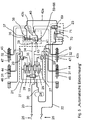
- a control pressure line 20 leads to a trailer brake module 21.
- a supply pressure line 22 leads to a parking release valve 23 and from there via a storage container 24 to the trailer brake module 21.
- the control pressure line 20 has a yellow coupling head 25 for a control connection and the supply pressure line 22 has one red coupling head 26 for a supply connection.
- the trailer brake module 21 is constructed in a known manner, namely with two solenoid valves 27, 28 and one relay valve 29 on each side of the vehicle.
- the supply of the control pressure to the relay valves 29 is regulated via the solenoid valves 27, 28.
- the latter are at the same time at the reservoir pressure via a line 30 with branches connected from the reservoir 24 and emit modulated service brake pressure to service brake cylinders 31, 32.
- a redundancy valve 33 as a solenoid valve, with which the connection between the control pressure line 20 and a line 34 can be separated and switched.
- the line 34 can alternatively be connected to the line 30 and the reservoir pressure from the reservoir 24.
- the line 34 also connects the solenoid valves 28 on both sides of the vehicle to one another via a branch 35.
- the line 34 (when the redundancy valve 33 is switched accordingly) connects the control pressure line 20 to a first control input 36 of a valve arrangement 37.
- the valve arrangement 37 in particular has the function of overload protection and for this purpose also has a second control input 38 and a first connection 39, a second connection 40 and a third connection 41, see also Figs. 1 to 3 .
- the second control input 38 is connected to the supply pressure line 22 via a line 42a and the parking release valve 23.
- the first connection 39 is connected to the storage container 24 via a line 42b, a check valve 43 and the trailer brake module 21.
- the second connection 40 is connected to spring-loaded brake cylinders 44, 45 on both sides of the vehicle via a line 42c and branches.
- the third connection 41 is a ventilation connection.
- the service brake cylinders 31, 32 are components of so-called combination cylinders, namely with integrated spring-loaded brake cylinders 44, 45, the forces acting on the same brake pistons 46, 47 when the service brake is actuated on the one hand and spring-loaded cylinders on the other.
- the valve arrangement 37 includes a valve unit 48 in the manner of a double piston valve, see Fig. 1-3 , here with a housing 49 in which two pistons 50, 51 can be moved coaxially to control the valve functions.
- the first piston 50 In an upper, first cylinder chamber 52, the first piston 50 is fed in via the control input 36 Control pressure can be moved downward in the direction of the second piston 51.
- the first piston 50 has a downwardly directed extension 53 with a reduced diameter, so that a second cylinder space 54 is formed around the extension 53 and below it.
- the second control input 38 leads into the second cylinder space 54 between the two pistons 50, 51. Due to the extension 53, the two pistons 50, 51 are always at a minimum distance from one another, so that the second control input 38 cannot be closed by the pistons 50, 51 .
- the second piston 51 is stepped with a wide head 55 with a seal 56 and a narrower extension 57 with a seal 58.
- the edge of the head 55 rests against a compression spring 59 which presses the second piston 51 in the direction of the first piston 50.
- the extension 57 of the second piston 51 is hollow and is provided with an opening 60 at the bottom and also with an opening 61 at the side near the head 55.
- the two openings 60, 61 are closed off from one another or separated from one another on the outside by the seal 58.
- an annular space 61a is formed around the extension 57, which in addition to the opening 61 also has the third connection 41 as an opening and is otherwise closed by the seals 56, 58.
- the housing 49 In its lower region, the housing 49 has a wider, lowest, annular cylinder space 62 and, above it, a somewhat narrower, annular cylinder space 63.
- the second connection 40 is at the same time an opening of the cylinder space 63 and the first connection 39 is an opening of the cylinder space 62.
- an inner circumferential edge 64 is formed, against which an auxiliary piston 65 held in the lowermost cylinder chamber 62 presses upwards by means of a compression spring 66.
- the compression spring 66 is relatively weak and only has the effect that the auxiliary piston 65, unless further forces act, rests against the circumferential edge 64 and closes off the lowermost cylinder chamber 62 there.
- the auxiliary piston 65 is preferably open at both axial ends and guided on the inside on a seal 67.
- the first piston 50 has a circumferential seal 68 on the outside.
- the extension 57 of the second piston 51 is guided in the cylinder space 63 with the seal 58 on the outside.
- the directions “up” and “down” relate to the orientation of the valve unit 48 in the figures.
- the valve unit 48 can assume a different position, so that the directional information must be adapted.
- the valve unit 48 is designed here as a 3/2-way valve, with an upper switch position in the Figures 2 , 5 , 6th and a lower switch position in the Fig. 1 , 3 , 4th , 7th . Due to the construction of the valve unit 48, the functions of the in Fig. 4 visible valve arrangement 37 combined in one housing (in housing 49). The functions of the valve arrangement 37 are described below with reference to FIG Figures 4-7 explained: In driving position according to Fig. 4 the pneumatic braking system is ready.
- the spring-loaded brake cylinders 44, 45 are ventilated by reservoir pressure from the reservoir 24.
- the first connection 39 is connected to the second connection 40 via the valve arrangement 37.
- the valve arrangement 37 is in an actively switched, second switching position. This second switching position is triggered by the supply pressure of at least 2.5 bar applied to the second control input 38 on the supply pressure line 22.
- the supply pressure is fed from the supply pressure line 22 through the parking release valve 23 and through the line 42a to the second control input 38.
- the supply pressure applied there acts on the second piston 51, so that the valve unit 48 is in the driving position according to FIG Fig. 1 occupies.
- There is no pressure at the first control input 36 the first piston 50 is not acted upon and is in its upper position. Since there is also no control pressure from the control pressure line 20, the brake cylinders 30, 31, 32 are also not ventilated.
- Fig. 5 shows the components of the pneumatic brake system after an automatic braking of the trailer vehicle due to loss of the supply pressure in the supply pressure line 22, for example due to the red coupling head being torn off.
- the second control input 38 is then also depressurized, as is the first control input 36 without actuation of the service brakes.
- both cylinder spaces 52, 54 are vented and both pistons 50, 51 are moved upwards by the pressure of spring 59, see also Fig. 2 .
- Fig. 4 is located in Fig. 5 the valve arrangement 37 in an upper switching position.
- the first connection 39 is blocked.
- the second connection 40 is connected to the third connection 41 for venting the spring-loaded brake cylinders 44, 45.
- the spring-loaded brake cylinders 44, 45 are vented and the trailer vehicle is braked or braked.
- the service brakes are inactive.
- a parking position of the pneumatic brake system is shown.
- the valve arrangement 37 assumes the same switching position as in FIG Fig. 5 during automatic braking after loss of supply pressure in supply pressure line 22.
- the supply pressure can still be present in the supply pressure line 22.
- the pressure loss at the second control input 38 is instead achieved by switching over the parking release valve 23.
- This includes at least two valves, namely a parking valve 69 and a release valve 70.
- the release valve 70 is in the same switching position in all the states shown here.
- the parking valve 69 is in the Fig. 4 and 5 in one driving position and only in Fig. 6 in a parking position.
- the second control input 38 is connected to a vent 71 on the parking valve 69 and is therefore pressureless.
- the service brake is inactive.
- the first control input 36 is also depressurized.
- the cylinder spaces 52, 54 are vented.
- the valve arrangement assumes the same position as in automatic braking in Fig. 5 .
- the second connection 40 is connected to the third connection 41 for venting the spring-loaded brake cylinder. The vehicle is braked.
- Fig. 7 the function of the valve arrangement 37 as overload protection can be seen.
- a double load within the service brake cylinders 30, 31 and 32 due to the actuation of the service brake on the one hand and the force of the vented spring-loaded brake cylinders 44, 45 on the other hand should be avoided.
- the parking position is assumed in accordance with Fig. 6 with switched parking valve 69.
- control pressure is also present in control pressure line 20. This regulates the supply of the reservoir pressure via the solenoid valves 27, 28 and relay valves 29 from the reservoir 24 to the service brake cylinders 31, 32. The more control pressure is applied, the higher the additional mechanical forces within the service brake cylinders 31, 32.
- the control pressure is also fed into the cylinder chamber 52 via the first control input 36, see Fig. 3 .
- the valve arrangement 37 switches from the park position according to Fig. 5 in the position according to Fig. 7 .
- the first connection 39 is connected to the second connection 40 and the spring-loaded brake cylinders 44, 45 are pressurized from the reservoir 24.
- the valve arrangement 37 switches to the position according to FIG Fig. 6 back and the spring-loaded brake cylinders 44, 45 are vented again.
- the ventilation and venting of the spring-loaded brake cylinders 44, 45 is not proportional to the change in the control pressure. Rather, the spring-loaded brake cylinders 44, 45 are vented or ventilated depending on whether a control pressure limit value is exceeded or not reached.
- the limit value here is 2.5 bar or more.
- the overload protection is also effective based on the in Fig. 5 (automatic braking) shown.
- the Figures 8-11 relate like that Figures 4-7 on the various driving position states ( Fig. 8 ), automatic braking ( Fig. 9 ), Parking position ( Fig. 10 ) and overload protection ( Fig. 11 ).
- the valve arrangement 37 is designed in a different way, namely not with a double piston valve, but with an additional select high valve 72 for controlling the two states of the valve arrangement 37 and the connection of the connections 39, 40, 41.
- the select high Valve 72 allows the higher of the pressure present at the two control inputs 36, 38 to pass through to a third control input 73.
- the valve arrangement 37 assumes the associated switching position.
- the select high valve 72 contains a non-return function between the control inputs 36, 38, so that the higher pressure applied in each case can only reach the control input 73 and cannot escape via the control input with the lower pressure.
- the sign of the pressure difference at the control inputs 36, 38 is in the Figures 8-11 recognizable from the position of a ball 74.
- Fig. 8 Driving position
- Fig. 9 automated braking
- the control input 38 is depressurized from the driving position by tearing off the supply pressure line 22, while the control input 36 is depressurized anyway.
- the ball 74 remains in front of the control input 36 until there is no longer any pressure at the control input 38 either.
- Fig. 10 (Parking position) is also the driving position according to Fig. 8 Starting point for the considerations.
- the driving position the full supply pressure is applied to control input 38 (as in Fig. 8 ).
- the vehicle is braked by means of the service brakes by regulating the control pressure.
- the service brakes are generally not actuated, that is, there is no longer any pressure at the control input 36 and at the same time the control input 38 is vented via the parking valve 69.
- the ball 74 remains in the position according to FIG Fig. 10 , so left.
- the spring-loaded brake cylinders 44, 45 are vented, the spring-loaded brakes hold the trailer vehicle.
- Fig. 11 (Overload protection) when the service brake is actuated during the parking position. It is then effective at the control input 36 control pressure.
- the ball 74 migrates to the right position according to FIG Fig. 11 and the control pressure reaches the control input 73 for switching over the valve arrangement 37.
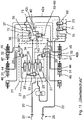
- FIG. 12 Another special feature shows Fig. 12 .
- Automatic braking is assumed ( Fig. 5 and 9 ).
- the second control input 38 is depressurized because the supply pressure line 22 is torn off.
- the trailer vehicle is strongly braked by the spring-loaded brake cylinders 44, 45.
- the wheels can lock.
- the anti-lock control that is usually present for the service brake is not effective.
- the redundancy valve 33 switches from the position of the Figures 4-11 in the position according to Fig. 12 .
- the control pressure no longer reaches the first control input 36 via the redundancy valve 33, but rather the supply container pressure from the supply container 24 via the line 30.
- the valve arrangement 37 accordingly switches to the position shown in FIG Fig.
- the trailer vehicle can now be braked using its own service brakes (service brake cylinders 31, 32) with reservoir pressure from the reservoir 24.
- the anti-lock braking control usually present in the trailer brake module 21 is effective here.
- An electronic brake system is assigned to the pneumatic brake system.
- a component of the electronic brake system is a brake control device, which is not shown here and which is integrated into the trailer brake module 21 or can also be present.
- the brake control device receives status information in a manner known per se via sensors on the pneumatic brake system and controls the functions of the trailer brake module 21. For example, control pressure and supply pressure are monitored, here preferably also the position of the valve arrangement 37 Pressure in the reservoir 24, the brake control device can switch the redundancy valve 33 into the position according to Fig. 12 and at the same time initiate emergency braking with anti-lock protection via the trailer brake module 21 with regulation of the valves 27, 28. Only if the If the reservoir 24 no longer has sufficient pressure, the redundancy valve 33 is not activated to switch over, so that automatic braking by the spring-loaded brake cylinders 44, 45 takes place.
- a longitudinal deceleration sensor 76 is connected to the brake control device in the trailer brake module 21 via a line 75. Its signals are processed in the brake control unit.
- the redundancy valve 33 preferably only switches to the position shown in FIG Fig. 12 when the longitudinal deceleration exceeds a limit value.
- the longitudinal deceleration sensor 76 can also be integrated into the brake control device or into the trailer brake module 21.
- FIG. 13 the details of the trailer brake module 21, the valve arrangement 37 and the parking release valve 23 that are visible in the other figures are not shown. Instead, other details of the trailer's pneumatic braking system are visible: Three axles (not shown in more detail) each carry two wheels 77, 78, 79. The wheels 78, 79 of the two rear axles are each assigned speed sensors 80, 81. Their signals are fed to the trailer brake module 21 via signal lines 82 and processed in the control unit integrated there.
- the trailer vehicle and the towing vehicle are connected to one another via an electrical line.
- an electrical interface 83 is provided parallel to the coupling heads 25, 26.
- An electrical line 84 leads from this to the trailer brake module 21.
- an electrical brake line according to ISO-11992 is Integrated into the electrical line 84, with which a braking request by the driver is transmitted from the towing vehicle to the trailer vehicle.
- the control unit in the trailer brake module 21 uses the signals sent via the electrical brake line on the one hand and the signals from the wheel speed sensors 80, 81 on the one hand to determine whether there is a braking request and / or at least one wheel is blocked when the trailer vehicle is moving. If there is no braking request and at least one wheel blocks while driving, the control unit regulates the pneumatic brake system in such a way that the spring-loaded brake cylinders 44, 45 are ventilated and the service brakes with anti-lock control are automatically activated to perform full braking. Since the control unit carries out the braking and the driver is not involved, the braking can also be carried out according to a program stored in the control unit with less braking force than with full braking.
Landscapes
- Engineering & Computer Science (AREA)
- Transportation (AREA)
- Mechanical Engineering (AREA)
- Regulating Braking Force (AREA)
- Braking Systems And Boosters (AREA)
- Valves And Accessory Devices For Braking Systems (AREA)
Claims (7)
- Procédé permettant la régulation de freins dans un véhicule tracté avec un système de freinage pneumatique, des freins de service et un système de freinage électronique à régulation antiblocage des roues,
dans lequel au moins un essieu du véhicule tracté est équipé de freins à ressort et de capteurs de vitesse de rotation, et dans lequel le système de freinage pneumatique présente en particulier un réservoir de stockage (24) avec une pression de réservoir de stockage, dans lequela) le système de freinage électronique surveille si un souhait de freinage est présent,b) le système de freinage électronique surveille si au moins une roue (78, 79) de l'au moins un essieu se bloque,c) si aucun souhait de freinage n'est présent et au moins une roue (78, 79) de l'au moins un essieu se bloque pendant la marche, le système de freinage électronique régule le système de freinage pneumatique de telle sorte que les freins à ressort sont aérés et le véhicule tracté est freiné automatiquement par les freins de service et avec régulation antiblocage des roues, caractérisé en ce qu'une unité soupape (48) à commande pneumatique aère les freins à ressort avec la pression de réservoir de stockage lorsqu'une pression de commande au-dessus d'une valeur limite s'applique contre une entrée de commande de l'unité soupape (48), et que, pour le déclenchement de l'aération des freins à ressort, la pression de réservoir de stockage est amenée à l'entrée de commande de l'unité soupape (48). - Procédé selon la revendication 1, caractérisé en ce qu'un souhait de freinage est présent lorsqu'une pression au-dessus d'une valeur limite est mesurée dans une conduite de pression de commande pneumatique (22) dans le véhicule tracté ou dans un véhicule tracteur du véhicule tracté ou lorsqu'un signal servant à actionner le frein de service est transmis à une conduite de freinage électrique.
- Procédé selon la revendication 1 ou 2, caractérisé en ce que le véhicule tracté est freiné jusqu'à l'arrêt.
- Procédé selon la revendication 1 ou l'une des autres revendications, caractérisé en ce qu'une décélération longitudinale du véhicule tracté est surveillée et que le véhicule tracté n'est freiné automatiquement et les freins à ressort ne sont aérés que lorsque la décélération longitudinale passe au-dessus d'une valeur limite.
- Ensemble soupape (37) pour un système de freinage pneumatique d'un véhicule tracté, en particulier en liaison avec un système de freinage électronique, dans lequel le système de freinage pneumatique présente un réservoir de stockage (24) avec une pression de réservoir de stockage,
avec une unité soupape (48) à commande pneumatique servant à aérer les freins de service avec une pression de réservoir de stockage, dans la mesure où une pression au-dessus d'une valeur limite s'applique contre une entrée de commande (36) de l'unité soupape (48), et avec une électrovanne (33), laquelle est d'une part raccordée à une pression de commande du système de freinage pneumatique et à la pression de réservoir de stockage et peut basculer entre la pression de commande et la pression de réservoir de stockage, et laquelle est d'autre part reliée à l'entrée de commande (36) de l'unité soupape (48), de sorte que la pression de commande ou pression de réservoir de stockage s'applique contre l'entrée de commande (36) de l'unité soupape (48), en fonction de la position de l'électrovanne. - Véhicule tracté avec un système de freinage pneumatique, un système de freinage électronique et un ensemble soupape (37) selon la revendication 5.
- Appareil de commande électronique permettant de mettre en œuvre le procédé selon l'une quelconque des revendications 1 à 4, pour la commande d'un ensemble soupape (37) selon la revendication 5 et/ou pour un véhicule tracté selon la revendication 6.
Applications Claiming Priority (2)
| Application Number | Priority Date | Filing Date | Title |
|---|---|---|---|
| DE102015007384.2A DE102015007384A1 (de) | 2015-06-10 | 2015-06-10 | Verfahren zum Regeln von Bremsen in einem Anhängefahrzeug |
| PCT/EP2016/000920 WO2016198152A1 (fr) | 2015-06-10 | 2016-06-04 | Procédé de commande de frein dans une remorque |
Publications (3)
| Publication Number | Publication Date |
|---|---|
| EP3307595A1 EP3307595A1 (fr) | 2018-04-18 |
| EP3307595B1 true EP3307595B1 (fr) | 2021-03-17 |
| EP3307595B8 EP3307595B8 (fr) | 2021-06-02 |
Family
ID=56132880
Family Applications (1)
| Application Number | Title | Priority Date | Filing Date |
|---|---|---|---|
| EP16729489.1A Active EP3307595B8 (fr) | 2015-06-10 | 2016-06-04 | Procédé de commande de frein dans une remorque |
Country Status (5)
| Country | Link |
|---|---|
| US (1) | US10717423B2 (fr) |
| EP (1) | EP3307595B8 (fr) |
| CN (1) | CN107531222B (fr) |
| DE (1) | DE102015007384A1 (fr) |
| WO (1) | WO2016198152A1 (fr) |
Families Citing this family (8)
| Publication number | Priority date | Publication date | Assignee | Title |
|---|---|---|---|---|
| DE102015007383A1 (de) * | 2015-06-10 | 2016-12-15 | Wabco Gmbh | Pneumatische Bremsanlage für ein Anhängefahrzeug |
| DE102016010639A1 (de) | 2016-09-02 | 2018-03-08 | Wabco Gmbh | Pneumatische Bremsanlage für ein Anhängerfahrzeug |
| US20180201144A1 (en) * | 2017-01-13 | 2018-07-19 | NextEv USA, Inc. | Authentication using electromagnet signal detection |
| DE102018108005A1 (de) | 2018-04-05 | 2019-10-10 | Knorr-Bremse Systeme für Nutzfahrzeuge GmbH | Steuereinrichtung für eine Parkbremseinrichtung eines Fahrzeugs |
| US10780872B2 (en) * | 2018-04-17 | 2020-09-22 | Bendix Commercial Vehicle Systems Llc | Apparatus and method for trailer service brake control |
| CN116215476A (zh) * | 2023-03-31 | 2023-06-06 | 北京福田戴姆勒汽车有限公司 | 车辆防抱死制动系统及其控制方法和车辆 |
| DE102023120278A1 (de) | 2023-07-31 | 2025-02-06 | Zf Cv Systems Global Gmbh | Verfahren zur Prüfung eines pneumatischen Bremssystems, Bremssystem, Steuermodul und Fahrzeug |
| GB202413708D0 (en) * | 2024-09-17 | 2024-10-30 | Knorr Bremse Ag | Trailer braking system |
Family Cites Families (20)
| Publication number | Priority date | Publication date | Assignee | Title |
|---|---|---|---|---|
| DE3544356A1 (de) | 1985-12-14 | 1987-06-19 | Wabco Westinghouse Fahrzeug | Druckmittelbetaetigte bremsanlage |
| DE19942533A1 (de) * | 1999-09-07 | 2000-11-30 | Daimler Chrysler Ag | Bremsvorrichtung für Fahrzeuge, insbesondere für druckluftgebremste Nutzfahrzeuge |
| EP1188634B2 (fr) * | 2000-09-14 | 2011-12-21 | WABCO GmbH | Soupape de frein de remorque pour remorques à commande de freinage électronique et à sécurité améliorée de remorque stationnée |
| US7784879B2 (en) * | 2002-07-16 | 2010-08-31 | Haldex Brake Corporation | Electronic control air management with parking brake and trailer supply control |
| DE10233018A1 (de) | 2002-07-20 | 2004-01-29 | Iveco Magirus Ag | Verfahren und Bremsvorrichtung zur Feststell-Bremsung von Fahrzeugen , insbesondere Lastkraftwagen |
| DE10356672B4 (de) | 2003-12-04 | 2006-10-19 | Knorr-Bremse Systeme für Nutzfahrzeuge GmbH | Bremsanlage in einem Fahrzeug |
| US7971942B2 (en) * | 2006-09-19 | 2011-07-05 | Wabco Gmbh | Trailer brake system |
| DE102007021646A1 (de) * | 2007-05-09 | 2008-11-13 | Wabco Gmbh | Modulator |
| DE102007053764B4 (de) * | 2007-11-12 | 2009-08-20 | Haldex Brake Products Gmbh | Bremsanlage für einen Anhänger eines Kraftfahrzeuges |
| DE102008009882A1 (de) * | 2008-02-19 | 2009-08-20 | Wabco Gmbh | Feststellbremse für ein Fahrzeug und Verfahren zum Betrieb der Feststellbremse |
| DE102009031851B4 (de) * | 2009-07-03 | 2021-02-11 | Dipl. Ing. Tietjen Gmbh | Verfahren zur Abbremsung einer Zugfahrzeug-Anhänger-Kombination und Einrichtung |
| DE102009031785A1 (de) * | 2009-07-06 | 2011-01-13 | Wabco Gmbh | Pneumatische Bremsanlage für ein Anhängefahrzeug und Bremssteuermodulator |
| GB2490925B (en) | 2011-05-18 | 2017-05-10 | Haldex Brake Prod Ab | Vehicle braking system |
| GB2492124B (en) | 2011-06-22 | 2017-08-09 | Haldex Brake Prod Ab | Vehicle braking system |
| DE102012101871B4 (de) * | 2012-03-06 | 2013-12-12 | Haldex Brake Products Gmbh | Parkbremsventileinrichtung und pneumatische Anhänger-Druckluftbremsanlage |
| CN202541518U (zh) * | 2012-04-26 | 2012-11-21 | 青岛四方车辆研究所有限公司 | 城轨车辆停放制动控制单元的强迫缓解阀 |
| DE102013100538B4 (de) * | 2013-01-18 | 2016-06-02 | Haldex Brake Products Gmbh | Druckluftanlage eines Anhängers eines Nutzfahrzeugs |
| DE102013106260B4 (de) | 2013-06-17 | 2022-05-25 | Haldex Brake Products Aktiebolag | Elektropneumatische Bremsanlage |
| DE102013017875A1 (de) * | 2013-10-26 | 2015-05-21 | Wabco Gmbh | Relaisventil, Ventileinrichtung sowie Fahrzeug damit |
| CN104149769B (zh) * | 2014-08-05 | 2016-09-28 | 常州南车铁马科技实业有限公司 | 轨道车辆基础制动装置的防叠加阀 |
-
2015
- 2015-06-10 DE DE102015007384.2A patent/DE102015007384A1/de not_active Withdrawn
-
2016
- 2016-06-04 WO PCT/EP2016/000920 patent/WO2016198152A1/fr not_active Ceased
- 2016-06-04 US US15/580,807 patent/US10717423B2/en active Active
- 2016-06-04 EP EP16729489.1A patent/EP3307595B8/fr active Active
- 2016-06-04 CN CN201680025370.8A patent/CN107531222B/zh active Active
Non-Patent Citations (1)
| Title |
|---|
| None * |
Also Published As
| Publication number | Publication date |
|---|---|
| CN107531222B (zh) | 2021-06-08 |
| WO2016198152A1 (fr) | 2016-12-15 |
| US10717423B2 (en) | 2020-07-21 |
| EP3307595A1 (fr) | 2018-04-18 |
| DE102015007384A1 (de) | 2016-12-15 |
| CN107531222A (zh) | 2018-01-02 |
| EP3307595B8 (fr) | 2021-06-02 |
| US20180222463A1 (en) | 2018-08-09 |
Similar Documents
| Publication | Publication Date | Title |
|---|---|---|
| EP3600991B1 (fr) | Frein à main électro-pneumatique avec tcv integré (commande scandinave) | |
| EP2567874B1 (fr) | Composant de soupape pour une installation de freinage d'une remorque | |
| EP3247596B2 (fr) | Système de freinage électronique pour vehicule | |
| DE102007038472B4 (de) | Ventilanordnung zur Steuerung einer Bremsanlage eines Anhängerfahrzeugs | |
| EP2650183B1 (fr) | Dispositif de soupape de frein de stationnement et installation de freinage à air comprimé pneumatique pour remorque | |
| WO2016198152A1 (fr) | Procédé de commande de frein dans une remorque | |
| DE102017006356A1 (de) | Elektro-Pneumatische Handbremse (EPH) mit integriertem TCV (Europäische Ansteuerung) | |
| EP2631131B1 (fr) | Véhicule de traction agricole | |
| EP3307594B2 (fr) | Système de frein pneumatique pour un véhicule tracté | |
| EP3112230A1 (fr) | Module de frein de stationnement, installation de freinage et vehicule ainsi equipe et procede de fonctionnement d'un dispositif de frein de stationnement avec un tel module | |
| DE102013007881A1 (de) | Verfahren zur Abbremsung einer Zugfahrzeug-Anhängerkombination mit reduzierter Anhängerbremskraft abhängig vom Ansprechen des Zugfahrzeug-ABS | |
| EP3190014B1 (fr) | Installation de freinage pour un tracteur | |
| EP2426021A1 (fr) | Soupape de stationnement pour une remorque de véhicule utilitaire | |
| EP3507148B1 (fr) | Système de freinage pneumatique pour un véhicule tracté | |
| DE102022114280A1 (de) | Verfahren und Vorrichtung zum sicheren Bremsen eines Anhängers | |
| EP4366994B1 (fr) | Ensemble soupape électropneumatique doté d'une soupape de sécurité à verrouillage automatique | |
| EP2082935B1 (fr) | Dispositif de freinage d'une remorque ayant au moins deux axes et comprenant un axe avant articulé d'une combinaison de remorque de véhicule de traction | |
| WO2019115030A1 (fr) | Dispositif de soupape pneumatique pour un véhicule remorque | |
| EP2239172B1 (fr) | Procédé de fonctionnement d'un dispositif de freinage d'un véhicule automobile pénétrant une zone de stationnement | |
| DE102014116732B4 (de) | Bremseinrichtung eines Fahrzeugs mit elektrischer und durch eine pneumatische Notzuspanneinrichtung zuspannbarer Feststellbremse sowie Fahrzeug mit einer solchen Bremseinrichtung | |
| EP4304904A1 (fr) | Procédé de fonctionnement d'un système de frein de stationnement électropneumatique et système de frein de stationnement électropneumatique | |
| DE102020106426A1 (de) | Achsmodulator eines Kraftfahrzeugs | |
| DE102023134202B3 (de) | Bremsanlage eines Fahrzeugs mit redundanter Parkbremsfunktion | |
| DE102019130761A1 (de) | Ventileinheit für eine pneumatische Bremsanlage eines Anhängefahrzeugs |
Legal Events
| Date | Code | Title | Description |
|---|---|---|---|
| STAA | Information on the status of an ep patent application or granted ep patent |
Free format text: STATUS: THE INTERNATIONAL PUBLICATION HAS BEEN MADE |
|
| PUAI | Public reference made under article 153(3) epc to a published international application that has entered the european phase |
Free format text: ORIGINAL CODE: 0009012 |
|
| STAA | Information on the status of an ep patent application or granted ep patent |
Free format text: STATUS: REQUEST FOR EXAMINATION WAS MADE |
|
| 17P | Request for examination filed |
Effective date: 20180110 |
|
| AK | Designated contracting states |
Kind code of ref document: A1 Designated state(s): AL AT BE BG CH CY CZ DE DK EE ES FI FR GB GR HR HU IE IS IT LI LT LU LV MC MK MT NL NO PL PT RO RS SE SI SK SM TR |
|
| AX | Request for extension of the european patent |
Extension state: BA ME |
|
| DAV | Request for validation of the european patent (deleted) | ||
| DAX | Request for extension of the european patent (deleted) | ||
| GRAP | Despatch of communication of intention to grant a patent |
Free format text: ORIGINAL CODE: EPIDOSNIGR1 |
|
| STAA | Information on the status of an ep patent application or granted ep patent |
Free format text: STATUS: GRANT OF PATENT IS INTENDED |
|
| GRAJ | Information related to disapproval of communication of intention to grant by the applicant or resumption of examination proceedings by the epo deleted |
Free format text: ORIGINAL CODE: EPIDOSDIGR1 |
|
| STAA | Information on the status of an ep patent application or granted ep patent |
Free format text: STATUS: REQUEST FOR EXAMINATION WAS MADE |
|
| INTG | Intention to grant announced |
Effective date: 20201120 |
|
| INTC | Intention to grant announced (deleted) | ||
| GRAP | Despatch of communication of intention to grant a patent |
Free format text: ORIGINAL CODE: EPIDOSNIGR1 |
|
| STAA | Information on the status of an ep patent application or granted ep patent |
Free format text: STATUS: GRANT OF PATENT IS INTENDED |
|
| INTG | Intention to grant announced |
Effective date: 20210114 |
|
| GRAS | Grant fee paid |
Free format text: ORIGINAL CODE: EPIDOSNIGR3 |
|
| GRAA | (expected) grant |
Free format text: ORIGINAL CODE: 0009210 |
|
| STAA | Information on the status of an ep patent application or granted ep patent |
Free format text: STATUS: THE PATENT HAS BEEN GRANTED |
|
| AK | Designated contracting states |
Kind code of ref document: B1 Designated state(s): AL AT BE BG CH CY CZ DE DK EE ES FI FR GB GR HR HU IE IS IT LI LT LU LV MC MK MT NL NO PL PT RO RS SE SI SK SM TR |
|
| REG | Reference to a national code |
Ref country code: GB Ref legal event code: FG4D Free format text: NOT ENGLISH |
|
| REG | Reference to a national code |
Ref country code: CH Ref legal event code: EP |
|
| REG | Reference to a national code |
Ref country code: DE Ref legal event code: R096 Ref document number: 502016012607 Country of ref document: DE |
|
| REG | Reference to a national code |
Ref country code: IE Ref legal event code: FG4D Free format text: LANGUAGE OF EP DOCUMENT: GERMAN |
|
| REG | Reference to a national code |
Ref country code: AT Ref legal event code: REF Ref document number: 1371965 Country of ref document: AT Kind code of ref document: T Effective date: 20210415 |
|
| REG | Reference to a national code |
Ref country code: DE Ref legal event code: R081 Ref document number: 502016012607 Country of ref document: DE Owner name: ZF CV SYSTEMS EUROPE BV, BE Free format text: FORMER OWNER: WABCO GMBH, 30453 HANNOVER, DE Ref country code: CH Ref legal event code: PK Free format text: BERICHTIGUNG B8 |
|
| RAP4 | Party data changed (patent owner data changed or rights of a patent transferred) |
Owner name: ZF CV SYSTEMS HANNOVER GMBH |
|
| REG | Reference to a national code |
Ref country code: LT Ref legal event code: MG9D |
|
| PG25 | Lapsed in a contracting state [announced via postgrant information from national office to epo] |
Ref country code: BG Free format text: LAPSE BECAUSE OF FAILURE TO SUBMIT A TRANSLATION OF THE DESCRIPTION OR TO PAY THE FEE WITHIN THE PRESCRIBED TIME-LIMIT Effective date: 20210617 Ref country code: GR Free format text: LAPSE BECAUSE OF FAILURE TO SUBMIT A TRANSLATION OF THE DESCRIPTION OR TO PAY THE FEE WITHIN THE PRESCRIBED TIME-LIMIT Effective date: 20210618 Ref country code: HR Free format text: LAPSE BECAUSE OF FAILURE TO SUBMIT A TRANSLATION OF THE DESCRIPTION OR TO PAY THE FEE WITHIN THE PRESCRIBED TIME-LIMIT Effective date: 20210317 Ref country code: FI Free format text: LAPSE BECAUSE OF FAILURE TO SUBMIT A TRANSLATION OF THE DESCRIPTION OR TO PAY THE FEE WITHIN THE PRESCRIBED TIME-LIMIT Effective date: 20210317 Ref country code: NO Free format text: LAPSE BECAUSE OF FAILURE TO SUBMIT A TRANSLATION OF THE DESCRIPTION OR TO PAY THE FEE WITHIN THE PRESCRIBED TIME-LIMIT Effective date: 20210617 |
|
| REG | Reference to a national code |
Ref country code: NL Ref legal event code: MP Effective date: 20210317 |
|
| PG25 | Lapsed in a contracting state [announced via postgrant information from national office to epo] |
Ref country code: SE Free format text: LAPSE BECAUSE OF FAILURE TO SUBMIT A TRANSLATION OF THE DESCRIPTION OR TO PAY THE FEE WITHIN THE PRESCRIBED TIME-LIMIT Effective date: 20210317 Ref country code: RS Free format text: LAPSE BECAUSE OF FAILURE TO SUBMIT A TRANSLATION OF THE DESCRIPTION OR TO PAY THE FEE WITHIN THE PRESCRIBED TIME-LIMIT Effective date: 20210317 Ref country code: LV Free format text: LAPSE BECAUSE OF FAILURE TO SUBMIT A TRANSLATION OF THE DESCRIPTION OR TO PAY THE FEE WITHIN THE PRESCRIBED TIME-LIMIT Effective date: 20210317 |
|
| PG25 | Lapsed in a contracting state [announced via postgrant information from national office to epo] |
Ref country code: NL Free format text: LAPSE BECAUSE OF FAILURE TO SUBMIT A TRANSLATION OF THE DESCRIPTION OR TO PAY THE FEE WITHIN THE PRESCRIBED TIME-LIMIT Effective date: 20210317 |
|
| PG25 | Lapsed in a contracting state [announced via postgrant information from national office to epo] |
Ref country code: EE Free format text: LAPSE BECAUSE OF FAILURE TO SUBMIT A TRANSLATION OF THE DESCRIPTION OR TO PAY THE FEE WITHIN THE PRESCRIBED TIME-LIMIT Effective date: 20210317 Ref country code: CZ Free format text: LAPSE BECAUSE OF FAILURE TO SUBMIT A TRANSLATION OF THE DESCRIPTION OR TO PAY THE FEE WITHIN THE PRESCRIBED TIME-LIMIT Effective date: 20210317 Ref country code: LT Free format text: LAPSE BECAUSE OF FAILURE TO SUBMIT A TRANSLATION OF THE DESCRIPTION OR TO PAY THE FEE WITHIN THE PRESCRIBED TIME-LIMIT Effective date: 20210317 Ref country code: SM Free format text: LAPSE BECAUSE OF FAILURE TO SUBMIT A TRANSLATION OF THE DESCRIPTION OR TO PAY THE FEE WITHIN THE PRESCRIBED TIME-LIMIT Effective date: 20210317 |
|
| PG25 | Lapsed in a contracting state [announced via postgrant information from national office to epo] |
Ref country code: IS Free format text: LAPSE BECAUSE OF FAILURE TO SUBMIT A TRANSLATION OF THE DESCRIPTION OR TO PAY THE FEE WITHIN THE PRESCRIBED TIME-LIMIT Effective date: 20210717 Ref country code: PL Free format text: LAPSE BECAUSE OF FAILURE TO SUBMIT A TRANSLATION OF THE DESCRIPTION OR TO PAY THE FEE WITHIN THE PRESCRIBED TIME-LIMIT Effective date: 20210317 Ref country code: PT Free format text: LAPSE BECAUSE OF FAILURE TO SUBMIT A TRANSLATION OF THE DESCRIPTION OR TO PAY THE FEE WITHIN THE PRESCRIBED TIME-LIMIT Effective date: 20210719 Ref country code: SK Free format text: LAPSE BECAUSE OF FAILURE TO SUBMIT A TRANSLATION OF THE DESCRIPTION OR TO PAY THE FEE WITHIN THE PRESCRIBED TIME-LIMIT Effective date: 20210317 Ref country code: RO Free format text: LAPSE BECAUSE OF FAILURE TO SUBMIT A TRANSLATION OF THE DESCRIPTION OR TO PAY THE FEE WITHIN THE PRESCRIBED TIME-LIMIT Effective date: 20210317 |
|
| REG | Reference to a national code |
Ref country code: DE Ref legal event code: R097 Ref document number: 502016012607 Country of ref document: DE |
|
| PLBE | No opposition filed within time limit |
Free format text: ORIGINAL CODE: 0009261 |
|
| STAA | Information on the status of an ep patent application or granted ep patent |
Free format text: STATUS: NO OPPOSITION FILED WITHIN TIME LIMIT |
|
| PG25 | Lapsed in a contracting state [announced via postgrant information from national office to epo] |
Ref country code: MC Free format text: LAPSE BECAUSE OF FAILURE TO SUBMIT A TRANSLATION OF THE DESCRIPTION OR TO PAY THE FEE WITHIN THE PRESCRIBED TIME-LIMIT Effective date: 20210317 Ref country code: AL Free format text: LAPSE BECAUSE OF FAILURE TO SUBMIT A TRANSLATION OF THE DESCRIPTION OR TO PAY THE FEE WITHIN THE PRESCRIBED TIME-LIMIT Effective date: 20210317 Ref country code: ES Free format text: LAPSE BECAUSE OF FAILURE TO SUBMIT A TRANSLATION OF THE DESCRIPTION OR TO PAY THE FEE WITHIN THE PRESCRIBED TIME-LIMIT Effective date: 20210317 Ref country code: DK Free format text: LAPSE BECAUSE OF FAILURE TO SUBMIT A TRANSLATION OF THE DESCRIPTION OR TO PAY THE FEE WITHIN THE PRESCRIBED TIME-LIMIT Effective date: 20210317 |
|
| REG | Reference to a national code |
Ref country code: CH Ref legal event code: PL |
|
| 26N | No opposition filed |
Effective date: 20211220 |
|
| PG25 | Lapsed in a contracting state [announced via postgrant information from national office to epo] |
Ref country code: SI Free format text: LAPSE BECAUSE OF FAILURE TO SUBMIT A TRANSLATION OF THE DESCRIPTION OR TO PAY THE FEE WITHIN THE PRESCRIBED TIME-LIMIT Effective date: 20210317 |
|
| REG | Reference to a national code |
Ref country code: BE Ref legal event code: MM Effective date: 20210630 |
|
| REG | Reference to a national code |
Ref country code: DE Ref legal event code: R081 Ref document number: 502016012607 Country of ref document: DE Owner name: ZF CV SYSTEMS EUROPE BV, BE Free format text: FORMER OWNER: ZF CV SYSTEMS HANNOVER GMBH, 30453 HANNOVER, DE |
|
| PG25 | Lapsed in a contracting state [announced via postgrant information from national office to epo] |
Ref country code: LU Free format text: LAPSE BECAUSE OF NON-PAYMENT OF DUE FEES Effective date: 20210604 |
|
| PG25 | Lapsed in a contracting state [announced via postgrant information from national office to epo] |
Ref country code: LI Free format text: LAPSE BECAUSE OF NON-PAYMENT OF DUE FEES Effective date: 20210630 Ref country code: IT Free format text: LAPSE BECAUSE OF FAILURE TO SUBMIT A TRANSLATION OF THE DESCRIPTION OR TO PAY THE FEE WITHIN THE PRESCRIBED TIME-LIMIT Effective date: 20210317 Ref country code: IE Free format text: LAPSE BECAUSE OF NON-PAYMENT OF DUE FEES Effective date: 20210604 Ref country code: CH Free format text: LAPSE BECAUSE OF NON-PAYMENT OF DUE FEES Effective date: 20210630 |
|
| PG25 | Lapsed in a contracting state [announced via postgrant information from national office to epo] |
Ref country code: IS Free format text: LAPSE BECAUSE OF FAILURE TO SUBMIT A TRANSLATION OF THE DESCRIPTION OR TO PAY THE FEE WITHIN THE PRESCRIBED TIME-LIMIT Effective date: 20210717 |
|
| PG25 | Lapsed in a contracting state [announced via postgrant information from national office to epo] |
Ref country code: BE Free format text: LAPSE BECAUSE OF NON-PAYMENT OF DUE FEES Effective date: 20210630 |
|
| REG | Reference to a national code |
Ref country code: AT Ref legal event code: MM01 Ref document number: 1371965 Country of ref document: AT Kind code of ref document: T Effective date: 20210604 |
|
| PG25 | Lapsed in a contracting state [announced via postgrant information from national office to epo] |
Ref country code: AT Free format text: LAPSE BECAUSE OF NON-PAYMENT OF DUE FEES Effective date: 20210604 |
|
| PG25 | Lapsed in a contracting state [announced via postgrant information from national office to epo] |
Ref country code: CY Free format text: LAPSE BECAUSE OF FAILURE TO SUBMIT A TRANSLATION OF THE DESCRIPTION OR TO PAY THE FEE WITHIN THE PRESCRIBED TIME-LIMIT Effective date: 20210317 |
|
| P01 | Opt-out of the competence of the unified patent court (upc) registered |
Effective date: 20230528 |
|
| PG25 | Lapsed in a contracting state [announced via postgrant information from national office to epo] |
Ref country code: HU Free format text: LAPSE BECAUSE OF FAILURE TO SUBMIT A TRANSLATION OF THE DESCRIPTION OR TO PAY THE FEE WITHIN THE PRESCRIBED TIME-LIMIT; INVALID AB INITIO Effective date: 20160604 |
|
| PG25 | Lapsed in a contracting state [announced via postgrant information from national office to epo] |
Ref country code: MK Free format text: LAPSE BECAUSE OF FAILURE TO SUBMIT A TRANSLATION OF THE DESCRIPTION OR TO PAY THE FEE WITHIN THE PRESCRIBED TIME-LIMIT Effective date: 20210317 |
|
| PGFP | Annual fee paid to national office [announced via postgrant information from national office to epo] |
Ref country code: FR Payment date: 20240328 Year of fee payment: 9 |
|
| PG25 | Lapsed in a contracting state [announced via postgrant information from national office to epo] |
Ref country code: TR Free format text: LAPSE BECAUSE OF FAILURE TO SUBMIT A TRANSLATION OF THE DESCRIPTION OR TO PAY THE FEE WITHIN THE PRESCRIBED TIME-LIMIT Effective date: 20210317 |
|
| PG25 | Lapsed in a contracting state [announced via postgrant information from national office to epo] |
Ref country code: MT Free format text: LAPSE BECAUSE OF FAILURE TO SUBMIT A TRANSLATION OF THE DESCRIPTION OR TO PAY THE FEE WITHIN THE PRESCRIBED TIME-LIMIT Effective date: 20210317 |
|
| PGFP | Annual fee paid to national office [announced via postgrant information from national office to epo] |
Ref country code: DE Payment date: 20250402 Year of fee payment: 10 |
|
| PGFP | Annual fee paid to national office [announced via postgrant information from national office to epo] |
Ref country code: GB Payment date: 20250401 Year of fee payment: 10 |
|
| PG25 | Lapsed in a contracting state [announced via postgrant information from national office to epo] |
Ref country code: FR Free format text: LAPSE BECAUSE OF NON-PAYMENT OF DUE FEES Effective date: 20250630 |