EP3308625B1 - Heuwerbungsmaschine - Google Patents
Heuwerbungsmaschine Download PDFInfo
- Publication number
- EP3308625B1 EP3308625B1 EP17200993.8A EP17200993A EP3308625B1 EP 3308625 B1 EP3308625 B1 EP 3308625B1 EP 17200993 A EP17200993 A EP 17200993A EP 3308625 B1 EP3308625 B1 EP 3308625B1
- Authority
- EP
- European Patent Office
- Prior art keywords
- sliding plate
- hay
- making machine
- rake
- accordance
- Prior art date
- Legal status (The legal status is an assumption and is not a legal conclusion. Google has not performed a legal analysis and makes no representation as to the accuracy of the status listed.)
- Active
Links
Images


Classifications
-
- A—HUMAN NECESSITIES
- A01—AGRICULTURE; FORESTRY; ANIMAL HUSBANDRY; HUNTING; TRAPPING; FISHING
- A01D—HARVESTING; MOWING
- A01D78/00—Haymakers with tines moving with respect to the machine
- A01D78/08—Haymakers with tines moving with respect to the machine with tine-carrying rotary heads or wheels
- A01D78/10—Haymakers with tines moving with respect to the machine with tine-carrying rotary heads or wheels the tines rotating about a substantially vertical axis
- A01D78/105—Ground support for rotors
Definitions
- the present invention relates to a haymaking machine, in particular in the form of a rotary swather, with at least one rake wheel which can be driven to rotate around an upright rake wheel axis and which is supported on the ground by a feeler trolley which has a sliding plate for flat support.
- Such a haymaking machine is from the DE 24 56 383 A1 known, in which a sliding plate is provided for surface support on the floor under the rake wheel.
- Rake tines described orbit can be arranged just behind the rake tines.
- the font DE 200 18 109 U1 shows a rotary swather with such an internal feeler wheel, while the writings DE 203 12 730 U1 or DE 10 2004 002 384 Show swathers with feeler wheels located outside the orbit.
- Such a single feeler wheel is problematic, however, if unevenness in the floor not only contains uniform transverse waves, but is formed non-uniformly over the working width of the rake top, for example in the form of bevels or longitudinal waves running more or less in the direction of travel. In this case, the feeler wheel runs in a depression and no longer has a lifting effect, while the rake tines penetrate a bottom crest that appears next to the lane of the feeler wheel.
- the script suggests DE 10 2004 002 384 A1 before arranging two feeler wheels spaced apart from one another transversely to the direction of travel in front of the gyro and let a third feeler wheel run in the center behind the gyroscope.
- a tactile trolley is again problematic with regard to collisions with harvested swaths that have already been put together, in particular in the case of swaths with a plurality of rake rotors, which optionally produce single swaths or multiple swaths.
- the present invention is therefore based on the object of creating an improved haymaking machine of the type mentioned at the outset which avoids the disadvantages of the prior art and advantageously develops the latter.
- an improved ground adaptation should also be achieved in the case of uneven ground irregularities transverse to the direction of travel, which better avoids pricking in of the rake tines without having to buy this with an increased tendency of the feeler chassis to tangle on the already swathed or still to be combined crop.
- the tactile trolley includes a sliding plate for flat support on the floor. With a sufficiently wide design of the sliding plate transversely to the direction of travel, a significantly improved adaptation to the ground and bridging of ground holes, trenches in the direction of travel and also trenches transversely to the direction of travel can be achieved, whereby even on soft soils the risk of punctual sinking, as is the case with individual sensing wheels, is avoided can be.
- the feeler undercarriage comprises at least one feeler wheel which projects downward beyond the contact surface of the sliding plate.
- the sliding plate mentioned can in principle be contoured differently, for example in the form of an arcuate contoured, in particular circular or semicircular plate, or else have a closed ring shape.
- the sliding plate mentioned extends in an arc around the rake wheel axis and / or has a sickle-shaped or U-shaped contour in plan view.
- the said sliding plate can extend in or over a sector which lies in front of the upright rake wheel axis and / or includes a straight line of travel running through the rake wheel axis.
- the said sliding plate has a width which corresponds to at least half of the inside diameter of the orbit described by the rake teeth of the rake wheel.
- Said rake wheel can usually have revolving support arms, on which not only a single rake tine but rather several spaced rake tines are arranged, so that the orbit described by the rake tines is a circular ring of a certain thickness.
- the farthest inside, ie closest to the rake wheel axis defines the inner diameter of the orbit, while the farthest outer rake, ie the most distant from the rake wheel axis defines the outer diameter of the orbit.
- the sliding divider mentioned is particularly internal, i.e. arranged within the orbit described by the rake teeth of the rake wheel. In this way, any collision with the crop to be raked or already swathed can be avoided, since the rake wheel in front of the sliding plate pulls the crop together or away before the sliding plate passes over the corresponding soil section.
- the width of the sliding plate transversely to the direction of travel can advantageously be approximately 75% to 99% of the aforementioned inner diameter of the orbit of the computing wheel described by the rake tines.
- the sliding plate can extend over the entire inner diameter of the orbit of the rake wheel tines while maintaining a sufficient collision tolerance.
- the sliding plate can extend over a sector of the computing wheel circle, which includes a straight line of travel passing through the computing wheel axis, in particular is symmetrical about this, and extends over at least 90 °, ie covers a forward-facing quarter circle sector.
- the said sliding plate can also extend over a larger sector, for example over more than 120 °, whereby the sliding plate can preferably also cover 180 ° around the rake wheel axis or an even larger sector.
- the sliding plate can have a contact area whose size is at least 20% of the inner circle area inscribed by the rake wheel.
- the inner circular area means the circular area whose diameter is defined by the orbit of the innermost rake. Depending on the contour of the sliding plate, its contact area can also be significantly larger.
- the underside of the sliding plate which forms the contact surface can in principle be designed differently, in an advantageous further development of the invention said underside can form a substantially flat contact surface which can advantageously be chamfered and / or bent on the edge side, in particular in the direction of the front edge sections, in order to glide smoothly over the floor and to avoid puncturing at the bottom contour edges.
- the sliding plate or its contact surface can in this case be formed in one piece, but may also be formed in several parts or comprise or be composed of several contact surface sections, in an advantageous further development of the invention such multiple contact surface pieces are advantageously arranged on the same level or in a common plane can lie.
- the sliding plate can be composed of two or more curved sliding plate sections, between which, for example, gap-shaped recesses can be provided.
- the underside of the sliding plate can also be provided with one or more wear elements, for example in the form of wear strips projecting downward from the rest of the contact surface and pointing in the direction of travel, for example made of plastic, which can advantageously be detached from, for example, a plate-shaped basic body of the sliding plate or can be attached interchangeably.
- a wear element can also be a plate-like wear element which is continuous or comprises several larger surface pieces and which can be applied to the underside of the base body of the sliding plate, in particular can be interchangeably attached, for example in the form of a plastic coating or plastic plate.
- the one or more feeler wheels can protrude downward from the underside of the sliding plate, for example be arranged in the area of sliding plate recesses, as is known, for example, in a similar manner in the case of water or amphibious aircraft or combined sliding-ski / wheel undercarriages on aircraft.
- the combined slide plate / feeler wheel chassis design only the feeler wheel or the several feeler wheels on the ground run on a level floor, while the slide plate has little or no contact with the ground. If, however, the feeler wheel travels into a hole or a longitudinal groove, the contact surface of the sliding plate sinks in or gets in contact with the ground and guides the rake wheel safely over the corresponding uneven ground.
- the above-mentioned sliding plate of the feeler undercarriage can be arranged or suspended rigidly with respect to the rake wheel or with respect to the rake wheel assembly - the rake wheel naturally rotates around - in order to scan unevenness in the floor without delay and to convert it into corresponding height movements of the rake wheel.
- the sliding plate mentioned can, however, also be resilient, in particular elastically suspended, for example by means of a rubber element bearing, so that impacts on the sliding plate can be absorbed and the haymaking machine runs smoothly overall.
- the suspension of the sliding plate can comprise several support points on the sliding plate, advantageously at least two support points to the right and left of the rake wheel axis and at least one support point in front of the rake wheel axis.
- the rotary swather 1 shown in the figures has a machine frame with which the rotary swather can be coupled to a tractor in a manner known per se, for example by means of a drawbar or a multi-point linkage, the machine frame being able to be supported on the ground, for example, by a rear-mounted running gear.
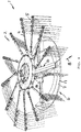
- a rake gyro 2 is mounted on the above-mentioned machine frame, for example by the in Fig. 2 Shown support arm, which can be pivoted on the above-mentioned machine frame about a lying axis, for example pointing in the direction of travel, in order to be able to lift the rake top 2 into a headland and transport position.
- the rake gyro 2 has a plurality of rake tines 5, which are fastened to support arms 19 which are arranged radially to an upright rake wheel axis 3, around which the said support arms 4 can be driven all round.
- the support arms 4 and thus the rake tines 5 attached thereto are cyclically rotated in their orbit around the rake wheel axis 3, so that the rake tines 5 rake over the ground in a predetermined sector and are pivoted away from the ground in the remaining part of the orbit.
- the rake tines 5 on the one hand, graze close to the ground to rake the crop, while on the other hand they fold up in the region of the swath that has already been merged, in order to deposit the crop in the swath.
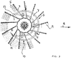
- a tactile undercarriage 6 on the ground which has a sliding plate 7 within the orbit 9 of the rake tines 5, which can support the rake gyroscope 2 over a large area on the ground.
- the sliding plate 7 can be curved, curved, in particular U-shaped or crescent-shaped, so that the sliding plate 7, viewed in the direction of travel 8 in front of the rake wheel axis 3, lies in the section of the inner diameter 7 of the rake wheel 2 about the rake wheel axis 3 extends around.
- Said sliding plate 7 can be formed in one piece or in several parts, for example composed of two quarter-circle pieces.
- the width 10 of the sliding plate 7 can substantially correspond to the inside diameter 11 of the orbit 9 of the rake tines 5 or be made slightly smaller in order to avoid collisions between the rake tines 5 and the sliding plate 7.
- the said sliding plate 7 can include an edge bend 17 or bevel on its edge, in particular its edge portion pointing forward in the direction of travel, but possibly also on its edge portion pointing rearward, in order to be able to slide more easily over uneven floors.
- the lower shell of the sliding plate 7 can be closed by a cover.
- the sliding plate can be designed cambered.
- the arcuate contoured sliding plate 7 extends over a sector 14 which includes a straight line 8 through the rake wheel axis 3 and extends over an angle 15 of approximately 240 °.
- a sector 14 which includes a straight line 8 through the rake wheel axis 3 and extends over an angle 15 of approximately 240 °.
- other shape-bound forms can also be provided here.
- the sliding plate 7 can be supported by means of a sliding plate suspension 16 on the central body of the computing circle 2, the said sliding plate suspension 16 advantageously being able to have several support points on the sliding plate 7, for example by means of support arms 18 which have 3 support points in front of and to the right and left of the computing wheel axis form the sliding plate 7.
- Said slide plate suspension 16 can be rigid, but possibly also flexible, in particular elastic, for example by using rubber bearing elements between said support arms 18 and slide plate 17 and / or between support arms 18 and the rotor body.
Landscapes
- Life Sciences & Earth Sciences (AREA)
- Environmental Sciences (AREA)
- Soil Working Implements (AREA)
Priority Applications (1)
| Application Number | Priority Date | Filing Date | Title |
|---|---|---|---|
| SI201331746T SI3308625T1 (sl) | 2012-11-09 | 2013-11-07 | Stroj za pripravo sena |
Applications Claiming Priority (2)
| Application Number | Priority Date | Filing Date | Title |
|---|---|---|---|
| DE202012010746.1U DE202012010746U1 (de) | 2012-11-09 | 2012-11-09 | Heuwerbungsmaschine |
| EP13005252.5A EP2735221B1 (de) | 2012-11-09 | 2013-11-07 | Heuwerbungsmaschine |
Related Parent Applications (2)
| Application Number | Title | Priority Date | Filing Date |
|---|---|---|---|
| EP13005252.5A Division EP2735221B1 (de) | 2012-11-09 | 2013-11-07 | Heuwerbungsmaschine |
| EP13005252.5A Division-Into EP2735221B1 (de) | 2012-11-09 | 2013-11-07 | Heuwerbungsmaschine |
Publications (2)
| Publication Number | Publication Date |
|---|---|
| EP3308625A1 EP3308625A1 (de) | 2018-04-18 |
| EP3308625B1 true EP3308625B1 (de) | 2020-04-22 |
Family
ID=49553993
Family Applications (2)
| Application Number | Title | Priority Date | Filing Date |
|---|---|---|---|
| EP17200993.8A Active EP3308625B1 (de) | 2012-11-09 | 2013-11-07 | Heuwerbungsmaschine |
| EP13005252.5A Active EP2735221B1 (de) | 2012-11-09 | 2013-11-07 | Heuwerbungsmaschine |
Family Applications After (1)
| Application Number | Title | Priority Date | Filing Date |
|---|---|---|---|
| EP13005252.5A Active EP2735221B1 (de) | 2012-11-09 | 2013-11-07 | Heuwerbungsmaschine |
Country Status (4)
| Country | Link |
|---|---|
| EP (2) | EP3308625B1 (da) |
| DE (1) | DE202012010746U1 (da) |
| DK (1) | DK3308625T3 (da) |
| SI (1) | SI3308625T1 (da) |
Families Citing this family (1)
| Publication number | Priority date | Publication date | Assignee | Title |
|---|---|---|---|---|
| CN108029348B (zh) * | 2017-11-08 | 2023-07-21 | 江苏省农业科学院 | 一种搂草机作业性能检测装置及检测方法 |
Family Cites Families (11)
| Publication number | Priority date | Publication date | Assignee | Title |
|---|---|---|---|---|
| NL144814B (nl) * | 1967-02-20 | 1975-02-17 | Lely Nv C Van Der | Inrichting voor het bewerken van op de grond liggend gewas. |
| NL169814C (nl) * | 1973-04-13 | 1985-07-16 | Lely Nv C Van Der | Inrichting voor het maaien respectievelijk harken of schudden van zich op de grond bevindend gewas. |
| NL176215B (nl) * | 1974-08-15 | 1984-10-16 | Expert Nv | Inrichting voor het bewerken van gemaaid op het veld liggend gewas. |
| DE3208246A1 (de) * | 1982-03-08 | 1983-09-15 | Klöckner-Humboldt-Deutz AG Zweigniederlassung Fahr, 7702 Gottmadingen | Landwirtschaftliche maschine mit im bodenbereich arbeitenden werkzeugen |
| DE3535887A1 (de) * | 1985-10-08 | 1987-04-09 | Weidtmann Rainer Dipl Ing Dipl | Heuwerbungsmaschine |
| DE3610545A1 (de) * | 1986-03-27 | 1987-10-01 | Claas Saulgau Gmbh | Trommelschwader |
| DE3831163A1 (de) * | 1988-06-15 | 1989-12-21 | Josef Lesslhumer | Heuwerbungsmaschine |
| DE20018109U1 (de) | 2000-10-23 | 2001-01-11 | Gebr. Pöttinger GmbH, 86899 Landsberg | Kreiselschwader |
| DE20312730U1 (de) | 2003-08-14 | 2003-10-30 | Gebr. Pöttinger GmbH, 86899 Landsberg | Schwadkreisel |
| DE102004002384A1 (de) | 2004-01-15 | 2005-08-18 | Claas Saulgau Gmbh | Kreiselschwader |
| DE202009003771U1 (de) | 2009-03-17 | 2010-08-05 | Alois Pöttinger Maschinenfabrik Gmbh | Heuwerbungsmaschine |
-
2012
- 2012-11-09 DE DE202012010746.1U patent/DE202012010746U1/de not_active Expired - Lifetime
-
2013
- 2013-11-07 DK DK17200993.8T patent/DK3308625T3/da active
- 2013-11-07 EP EP17200993.8A patent/EP3308625B1/de active Active
- 2013-11-07 EP EP13005252.5A patent/EP2735221B1/de active Active
- 2013-11-07 SI SI201331746T patent/SI3308625T1/sl unknown
Non-Patent Citations (1)
| Title |
|---|
| None * |
Also Published As
| Publication number | Publication date |
|---|---|
| EP2735221A1 (de) | 2014-05-28 |
| DE202012010746U1 (de) | 2014-02-14 |
| SI3308625T1 (sl) | 2020-08-31 |
| EP3308625A1 (de) | 2018-04-18 |
| EP2735221B1 (de) | 2017-12-27 |
| DK3308625T3 (da) | 2020-06-15 |
Similar Documents
| Publication | Publication Date | Title |
|---|---|---|
| DE1582294C3 (da) | ||
| DE202010010038U1 (de) | Erntemaschine | |
| DE102014107515A1 (de) | Pflug mit mehreren an einem Pflugbalken angebrachten Pflugkörpern | |
| EP2368418A1 (de) | Vorrichtung zum Aufrichten von Halmgut | |
| DE102009017400A1 (de) | Erntemaschine | |
| DE3343847A1 (de) | Bodenbearbeitungswalze | |
| EP3308625B1 (de) | Heuwerbungsmaschine | |
| DE1782544C2 (de) | Kreiselzettwender | |
| DE1800497C3 (de) | Heuwerbungsmaschine | |
| DE102006061010B4 (de) | Erntemaschine | |
| DE3448165C2 (da) | ||
| DE102015002209A1 (de) | Heuwerbungsmaschine | |
| DE7018452U (de) | Kreiselschwadrechen. | |
| CH642817A5 (de) | Heuwerbungsmaschine zum schwaden und zetten. | |
| DE2946023C2 (da) | ||
| EP1493321B1 (de) | Heuwerbungsmaschine | |
| EP3332628B1 (de) | Landwirtschaftliche arbeitsmaschine | |
| DE10055538C2 (de) | Kartoffelerntemaschine | |
| DE202010005499U1 (de) | Kreiselschwader | |
| DE1482147A1 (de) | Heuwerbungsmaschine | |
| AT206689B (de) | Vorrichtung zum seitlichen Versetzen von am Boden liegendem Gut | |
| DE1482074C (de) | Heuwender | |
| DE1154303B (de) | Heuwerbungsmaschine | |
| DE3205518A1 (de) | Bodenbearbeitungsmaschine | |
| DE1482175B2 (de) | Kreiselheuwerbungsmaschine |
Legal Events
| Date | Code | Title | Description |
|---|---|---|---|
| PUAI | Public reference made under article 153(3) epc to a published international application that has entered the european phase |
Free format text: ORIGINAL CODE: 0009012 |
|
| STAA | Information on the status of an ep patent application or granted ep patent |
Free format text: STATUS: THE APPLICATION HAS BEEN PUBLISHED |
|
| AC | Divisional application: reference to earlier application |
Ref document number: 2735221 Country of ref document: EP Kind code of ref document: P |
|
| AK | Designated contracting states |
Kind code of ref document: A1 Designated state(s): AL AT BE BG CH CY CZ DE DK EE ES FI FR GB GR HR HU IE IS IT LI LT LU LV MC MK MT NL NO PL PT RO RS SE SI SK SM TR |
|
| STAA | Information on the status of an ep patent application or granted ep patent |
Free format text: STATUS: REQUEST FOR EXAMINATION WAS MADE |
|
| 17P | Request for examination filed |
Effective date: 20180704 |
|
| RBV | Designated contracting states (corrected) |
Designated state(s): AL AT BE BG CH CY CZ DE DK EE ES FI FR GB GR HR HU IE IS IT LI LT LU LV MC MK MT NL NO PL PT RO RS SE SI SK SM TR |
|
| GRAP | Despatch of communication of intention to grant a patent |
Free format text: ORIGINAL CODE: EPIDOSNIGR1 |
|
| STAA | Information on the status of an ep patent application or granted ep patent |
Free format text: STATUS: GRANT OF PATENT IS INTENDED |
|
| INTG | Intention to grant announced |
Effective date: 20191126 |
|
| GRAS | Grant fee paid |
Free format text: ORIGINAL CODE: EPIDOSNIGR3 |
|
| GRAA | (expected) grant |
Free format text: ORIGINAL CODE: 0009210 |
|
| STAA | Information on the status of an ep patent application or granted ep patent |
Free format text: STATUS: THE PATENT HAS BEEN GRANTED |
|
| AC | Divisional application: reference to earlier application |
Ref document number: 2735221 Country of ref document: EP Kind code of ref document: P |
|
| AK | Designated contracting states |
Kind code of ref document: B1 Designated state(s): AL AT BE BG CH CY CZ DE DK EE ES FI FR GB GR HR HU IE IS IT LI LT LU LV MC MK MT NL NO PL PT RO RS SE SI SK SM TR |
|
| REG | Reference to a national code |
Ref country code: CH Ref legal event code: EP |
|
| REG | Reference to a national code |
Ref country code: DE Ref legal event code: R096 Ref document number: 502013014631 Country of ref document: DE |
|
| REG | Reference to a national code |
Ref country code: IE Ref legal event code: FG4D Free format text: LANGUAGE OF EP DOCUMENT: GERMAN |
|
| REG | Reference to a national code |
Ref country code: AT Ref legal event code: REF Ref document number: 1258832 Country of ref document: AT Kind code of ref document: T Effective date: 20200515 |
|
| REG | Reference to a national code |
Ref country code: DK Ref legal event code: T3 Effective date: 20200610 |
|
| REG | Reference to a national code |
Ref country code: LT Ref legal event code: MG4D |
|
| REG | Reference to a national code |
Ref country code: NL Ref legal event code: MP Effective date: 20200422 |
|
| PG25 | Lapsed in a contracting state [announced via postgrant information from national office to epo] |
Ref country code: NL Free format text: LAPSE BECAUSE OF FAILURE TO SUBMIT A TRANSLATION OF THE DESCRIPTION OR TO PAY THE FEE WITHIN THE PRESCRIBED TIME-LIMIT Effective date: 20200422 Ref country code: PT Free format text: LAPSE BECAUSE OF FAILURE TO SUBMIT A TRANSLATION OF THE DESCRIPTION OR TO PAY THE FEE WITHIN THE PRESCRIBED TIME-LIMIT Effective date: 20200824 Ref country code: FI Free format text: LAPSE BECAUSE OF FAILURE TO SUBMIT A TRANSLATION OF THE DESCRIPTION OR TO PAY THE FEE WITHIN THE PRESCRIBED TIME-LIMIT Effective date: 20200422 Ref country code: LT Free format text: LAPSE BECAUSE OF FAILURE TO SUBMIT A TRANSLATION OF THE DESCRIPTION OR TO PAY THE FEE WITHIN THE PRESCRIBED TIME-LIMIT Effective date: 20200422 Ref country code: SE Free format text: LAPSE BECAUSE OF FAILURE TO SUBMIT A TRANSLATION OF THE DESCRIPTION OR TO PAY THE FEE WITHIN THE PRESCRIBED TIME-LIMIT Effective date: 20200422 Ref country code: IS Free format text: LAPSE BECAUSE OF FAILURE TO SUBMIT A TRANSLATION OF THE DESCRIPTION OR TO PAY THE FEE WITHIN THE PRESCRIBED TIME-LIMIT Effective date: 20200822 Ref country code: NO Free format text: LAPSE BECAUSE OF FAILURE TO SUBMIT A TRANSLATION OF THE DESCRIPTION OR TO PAY THE FEE WITHIN THE PRESCRIBED TIME-LIMIT Effective date: 20200722 Ref country code: GR Free format text: LAPSE BECAUSE OF FAILURE TO SUBMIT A TRANSLATION OF THE DESCRIPTION OR TO PAY THE FEE WITHIN THE PRESCRIBED TIME-LIMIT Effective date: 20200723 |
|
| PG25 | Lapsed in a contracting state [announced via postgrant information from national office to epo] |
Ref country code: BG Free format text: LAPSE BECAUSE OF FAILURE TO SUBMIT A TRANSLATION OF THE DESCRIPTION OR TO PAY THE FEE WITHIN THE PRESCRIBED TIME-LIMIT Effective date: 20200722 Ref country code: RS Free format text: LAPSE BECAUSE OF FAILURE TO SUBMIT A TRANSLATION OF THE DESCRIPTION OR TO PAY THE FEE WITHIN THE PRESCRIBED TIME-LIMIT Effective date: 20200422 Ref country code: HR Free format text: LAPSE BECAUSE OF FAILURE TO SUBMIT A TRANSLATION OF THE DESCRIPTION OR TO PAY THE FEE WITHIN THE PRESCRIBED TIME-LIMIT Effective date: 20200422 Ref country code: LV Free format text: LAPSE BECAUSE OF FAILURE TO SUBMIT A TRANSLATION OF THE DESCRIPTION OR TO PAY THE FEE WITHIN THE PRESCRIBED TIME-LIMIT Effective date: 20200422 |
|
| PG25 | Lapsed in a contracting state [announced via postgrant information from national office to epo] |
Ref country code: AL Free format text: LAPSE BECAUSE OF FAILURE TO SUBMIT A TRANSLATION OF THE DESCRIPTION OR TO PAY THE FEE WITHIN THE PRESCRIBED TIME-LIMIT Effective date: 20200422 |
|
| REG | Reference to a national code |
Ref country code: DE Ref legal event code: R097 Ref document number: 502013014631 Country of ref document: DE |
|
| PG25 | Lapsed in a contracting state [announced via postgrant information from national office to epo] |
Ref country code: SM Free format text: LAPSE BECAUSE OF FAILURE TO SUBMIT A TRANSLATION OF THE DESCRIPTION OR TO PAY THE FEE WITHIN THE PRESCRIBED TIME-LIMIT Effective date: 20200422 Ref country code: EE Free format text: LAPSE BECAUSE OF FAILURE TO SUBMIT A TRANSLATION OF THE DESCRIPTION OR TO PAY THE FEE WITHIN THE PRESCRIBED TIME-LIMIT Effective date: 20200422 Ref country code: RO Free format text: LAPSE BECAUSE OF FAILURE TO SUBMIT A TRANSLATION OF THE DESCRIPTION OR TO PAY THE FEE WITHIN THE PRESCRIBED TIME-LIMIT Effective date: 20200422 Ref country code: IT Free format text: LAPSE BECAUSE OF FAILURE TO SUBMIT A TRANSLATION OF THE DESCRIPTION OR TO PAY THE FEE WITHIN THE PRESCRIBED TIME-LIMIT Effective date: 20200422 Ref country code: CZ Free format text: LAPSE BECAUSE OF FAILURE TO SUBMIT A TRANSLATION OF THE DESCRIPTION OR TO PAY THE FEE WITHIN THE PRESCRIBED TIME-LIMIT Effective date: 20200422 Ref country code: ES Free format text: LAPSE BECAUSE OF FAILURE TO SUBMIT A TRANSLATION OF THE DESCRIPTION OR TO PAY THE FEE WITHIN THE PRESCRIBED TIME-LIMIT Effective date: 20200422 |
|
| PG25 | Lapsed in a contracting state [announced via postgrant information from national office to epo] |
Ref country code: PL Free format text: LAPSE BECAUSE OF FAILURE TO SUBMIT A TRANSLATION OF THE DESCRIPTION OR TO PAY THE FEE WITHIN THE PRESCRIBED TIME-LIMIT Effective date: 20200422 Ref country code: SK Free format text: LAPSE BECAUSE OF FAILURE TO SUBMIT A TRANSLATION OF THE DESCRIPTION OR TO PAY THE FEE WITHIN THE PRESCRIBED TIME-LIMIT Effective date: 20200422 |
|
| PLBE | No opposition filed within time limit |
Free format text: ORIGINAL CODE: 0009261 |
|
| STAA | Information on the status of an ep patent application or granted ep patent |
Free format text: STATUS: NO OPPOSITION FILED WITHIN TIME LIMIT |
|
| 26N | No opposition filed |
Effective date: 20210125 |
|
| PG25 | Lapsed in a contracting state [announced via postgrant information from national office to epo] |
Ref country code: MC Free format text: LAPSE BECAUSE OF FAILURE TO SUBMIT A TRANSLATION OF THE DESCRIPTION OR TO PAY THE FEE WITHIN THE PRESCRIBED TIME-LIMIT Effective date: 20200422 |
|
| REG | Reference to a national code |
Ref country code: CH Ref legal event code: PL |
|
| GBPC | Gb: european patent ceased through non-payment of renewal fee |
Effective date: 20201107 |
|
| PG25 | Lapsed in a contracting state [announced via postgrant information from national office to epo] |
Ref country code: LU Free format text: LAPSE BECAUSE OF NON-PAYMENT OF DUE FEES Effective date: 20201107 |
|
| REG | Reference to a national code |
Ref country code: BE Ref legal event code: MM Effective date: 20201130 |
|
| PG25 | Lapsed in a contracting state [announced via postgrant information from national office to epo] |
Ref country code: LI Free format text: LAPSE BECAUSE OF NON-PAYMENT OF DUE FEES Effective date: 20201130 Ref country code: CH Free format text: LAPSE BECAUSE OF NON-PAYMENT OF DUE FEES Effective date: 20201130 |
|
| PG25 | Lapsed in a contracting state [announced via postgrant information from national office to epo] |
Ref country code: GB Free format text: LAPSE BECAUSE OF NON-PAYMENT OF DUE FEES Effective date: 20201107 |
|
| REG | Reference to a national code |
Ref country code: AT Ref legal event code: MM01 Ref document number: 1258832 Country of ref document: AT Kind code of ref document: T Effective date: 20201107 |
|
| PG25 | Lapsed in a contracting state [announced via postgrant information from national office to epo] |
Ref country code: AT Free format text: LAPSE BECAUSE OF NON-PAYMENT OF DUE FEES Effective date: 20201107 |
|
| PG25 | Lapsed in a contracting state [announced via postgrant information from national office to epo] |
Ref country code: TR Free format text: LAPSE BECAUSE OF FAILURE TO SUBMIT A TRANSLATION OF THE DESCRIPTION OR TO PAY THE FEE WITHIN THE PRESCRIBED TIME-LIMIT Effective date: 20200422 Ref country code: MT Free format text: LAPSE BECAUSE OF FAILURE TO SUBMIT A TRANSLATION OF THE DESCRIPTION OR TO PAY THE FEE WITHIN THE PRESCRIBED TIME-LIMIT Effective date: 20200422 Ref country code: CY Free format text: LAPSE BECAUSE OF FAILURE TO SUBMIT A TRANSLATION OF THE DESCRIPTION OR TO PAY THE FEE WITHIN THE PRESCRIBED TIME-LIMIT Effective date: 20200422 |
|
| PG25 | Lapsed in a contracting state [announced via postgrant information from national office to epo] |
Ref country code: MK Free format text: LAPSE BECAUSE OF FAILURE TO SUBMIT A TRANSLATION OF THE DESCRIPTION OR TO PAY THE FEE WITHIN THE PRESCRIBED TIME-LIMIT Effective date: 20200422 |
|
| PG25 | Lapsed in a contracting state [announced via postgrant information from national office to epo] |
Ref country code: BE Free format text: LAPSE BECAUSE OF NON-PAYMENT OF DUE FEES Effective date: 20201130 |
|
| P01 | Opt-out of the competence of the unified patent court (upc) registered |
Effective date: 20230613 |
|
| PG25 | Lapsed in a contracting state [announced via postgrant information from national office to epo] |
Ref country code: IS Free format text: LAPSE BECAUSE OF NON-PAYMENT OF DUE FEES Effective date: 20200822 |
|
| PGFP | Annual fee paid to national office [announced via postgrant information from national office to epo] |
Ref country code: DE Payment date: 20251118 Year of fee payment: 13 |
|
| PGFP | Annual fee paid to national office [announced via postgrant information from national office to epo] |
Ref country code: DK Payment date: 20251125 Year of fee payment: 13 |
|
| PGFP | Annual fee paid to national office [announced via postgrant information from national office to epo] |
Ref country code: FR Payment date: 20251126 Year of fee payment: 13 |
|
| PGFP | Annual fee paid to national office [announced via postgrant information from national office to epo] |
Ref country code: IE Payment date: 20251125 Year of fee payment: 13 |
|
| PGFP | Annual fee paid to national office [announced via postgrant information from national office to epo] |
Ref country code: SI Payment date: 20251028 Year of fee payment: 13 |