EP3308933A1 - Dispositif et procédé de fabrication d'une tête de tube ainsi que tête de tube - Google Patents
Dispositif et procédé de fabrication d'une tête de tube ainsi que tête de tube Download PDFInfo
- Publication number
- EP3308933A1 EP3308933A1 EP17202178.4A EP17202178A EP3308933A1 EP 3308933 A1 EP3308933 A1 EP 3308933A1 EP 17202178 A EP17202178 A EP 17202178A EP 3308933 A1 EP3308933 A1 EP 3308933A1
- Authority
- EP
- European Patent Office
- Prior art keywords
- valve needle
- tube
- head
- valve
- mold
- Prior art date
- Legal status (The legal status is an assumption and is not a legal conclusion. Google has not performed a legal analysis and makes no representation as to the accuracy of the status listed.)
- Granted
Links
- 238000004519 manufacturing process Methods 0.000 title claims abstract description 20
- 238000000034 method Methods 0.000 title claims description 25
- 239000000463 material Substances 0.000 claims abstract description 118
- 230000004888 barrier function Effects 0.000 claims abstract description 27
- 238000001746 injection moulding Methods 0.000 claims abstract description 26
- 241000680172 Platytroctidae Species 0.000 claims abstract description 22
- 229920000573 polyethylene Polymers 0.000 claims abstract description 12
- 239000004698 Polyethylene Substances 0.000 claims abstract description 11
- 239000004743 Polypropylene Substances 0.000 claims abstract description 11
- 238000000465 moulding Methods 0.000 claims abstract description 11
- 229920001155 polypropylene Polymers 0.000 claims abstract description 11
- -1 polyethylene Polymers 0.000 claims abstract description 10
- 229920002647 polyamide Polymers 0.000 claims abstract description 7
- 239000004952 Polyamide Substances 0.000 claims abstract description 6
- 229920001903 high density polyethylene Polymers 0.000 claims abstract description 6
- 239000004700 high-density polyethylene Substances 0.000 claims abstract description 6
- 230000007704 transition Effects 0.000 claims description 15
- 229920003023 plastic Polymers 0.000 claims description 10
- 239000004033 plastic Substances 0.000 claims description 10
- 239000012530 fluid Substances 0.000 abstract description 6
- 238000002347 injection Methods 0.000 description 8
- 239000007924 injection Substances 0.000 description 8
- 238000007789 sealing Methods 0.000 description 8
- 229920000219 Ethylene vinyl alcohol Polymers 0.000 description 4
- UFRKOOWSQGXVKV-UHFFFAOYSA-N ethene;ethenol Chemical compound C=C.OC=C UFRKOOWSQGXVKV-UHFFFAOYSA-N 0.000 description 4
- 239000004715 ethylene vinyl alcohol Substances 0.000 description 4
- 239000000155 melt Substances 0.000 description 3
- 229920001721 polyimide Polymers 0.000 description 3
- 239000004642 Polyimide Substances 0.000 description 2
- 230000015572 biosynthetic process Effects 0.000 description 2
- 238000010276 construction Methods 0.000 description 2
- 238000010438 heat treatment Methods 0.000 description 2
- 238000007142 ring opening reaction Methods 0.000 description 2
- 239000011324 bead Substances 0.000 description 1
- 238000004891 communication Methods 0.000 description 1
- 238000001816 cooling Methods 0.000 description 1
- 230000032798 delamination Effects 0.000 description 1
- 238000011161 development Methods 0.000 description 1
- 238000005553 drilling Methods 0.000 description 1
- 238000001125 extrusion Methods 0.000 description 1
- 230000009969 flowable effect Effects 0.000 description 1
- 238000003780 insertion Methods 0.000 description 1
- 230000037431 insertion Effects 0.000 description 1
- 238000009434 installation Methods 0.000 description 1
- 238000009413 insulation Methods 0.000 description 1
- 239000000203 mixture Substances 0.000 description 1
- 229920000642 polymer Polymers 0.000 description 1
- 230000008092 positive effect Effects 0.000 description 1
- 239000007921 spray Substances 0.000 description 1
- 238000005507 spraying Methods 0.000 description 1
- 238000012360 testing method Methods 0.000 description 1
- 238000012546 transfer Methods 0.000 description 1
Images




Classifications
-
- B—PERFORMING OPERATIONS; TRANSPORTING
- B29—WORKING OF PLASTICS; WORKING OF SUBSTANCES IN A PLASTIC STATE IN GENERAL
- B29C—SHAPING OR JOINING OF PLASTICS; SHAPING OF MATERIAL IN A PLASTIC STATE, NOT OTHERWISE PROVIDED FOR; AFTER-TREATMENT OF THE SHAPED PRODUCTS, e.g. REPAIRING
- B29C45/00—Injection moulding, i.e. forcing the required volume of moulding material through a nozzle into a closed mould; Apparatus therefor
- B29C45/0003—Injection moulding, i.e. forcing the required volume of moulding material through a nozzle into a closed mould; Apparatus therefor of successively moulded portions rigidly joined to each other
-
- B—PERFORMING OPERATIONS; TRANSPORTING
- B29—WORKING OF PLASTICS; WORKING OF SUBSTANCES IN A PLASTIC STATE IN GENERAL
- B29C—SHAPING OR JOINING OF PLASTICS; SHAPING OF MATERIAL IN A PLASTIC STATE, NOT OTHERWISE PROVIDED FOR; AFTER-TREATMENT OF THE SHAPED PRODUCTS, e.g. REPAIRING
- B29C45/00—Injection moulding, i.e. forcing the required volume of moulding material through a nozzle into a closed mould; Apparatus therefor
- B29C45/16—Making multilayered or multicoloured articles
- B29C45/1603—Multi-way nozzles specially adapted therefor
-
- B—PERFORMING OPERATIONS; TRANSPORTING
- B29—WORKING OF PLASTICS; WORKING OF SUBSTANCES IN A PLASTIC STATE IN GENERAL
- B29C—SHAPING OR JOINING OF PLASTICS; SHAPING OF MATERIAL IN A PLASTIC STATE, NOT OTHERWISE PROVIDED FOR; AFTER-TREATMENT OF THE SHAPED PRODUCTS, e.g. REPAIRING
- B29C45/00—Injection moulding, i.e. forcing the required volume of moulding material through a nozzle into a closed mould; Apparatus therefor
- B29C45/17—Component parts, details or accessories; Auxiliary operations
- B29C45/26—Moulds
- B29C45/27—Sprue channels ; Runner channels or runner nozzles
- B29C45/28—Closure devices therefor
- B29C45/2896—Closure devices therefor extending in or through the mould cavity, e.g. valves mounted opposite the sprue channel
-
- B—PERFORMING OPERATIONS; TRANSPORTING
- B65—CONVEYING; PACKING; STORING; HANDLING THIN OR FILAMENTARY MATERIAL
- B65D—CONTAINERS FOR STORAGE OR TRANSPORT OF ARTICLES OR MATERIALS, e.g. BAGS, BARRELS, BOTTLES, BOXES, CANS, CARTONS, CRATES, DRUMS, JARS, TANKS, HOPPERS, FORWARDING CONTAINERS; ACCESSORIES, CLOSURES, OR FITTINGS THEREFOR; PACKAGING ELEMENTS; PACKAGES
- B65D35/00—Pliable tubular containers adapted to be permanently or temporarily deformed to expel contents, e.g. collapsible tubes for toothpaste or other plastic or semi-liquid material; Holders therefor
- B65D35/02—Body construction
-
- B—PERFORMING OPERATIONS; TRANSPORTING
- B29—WORKING OF PLASTICS; WORKING OF SUBSTANCES IN A PLASTIC STATE IN GENERAL
- B29C—SHAPING OR JOINING OF PLASTICS; SHAPING OF MATERIAL IN A PLASTIC STATE, NOT OTHERWISE PROVIDED FOR; AFTER-TREATMENT OF THE SHAPED PRODUCTS, e.g. REPAIRING
- B29C45/00—Injection moulding, i.e. forcing the required volume of moulding material through a nozzle into a closed mould; Apparatus therefor
- B29C45/17—Component parts, details or accessories; Auxiliary operations
- B29C45/26—Moulds
- B29C45/27—Sprue channels ; Runner channels or runner nozzles
- B29C45/2701—Details not specific to hot or cold runner channels
- B29C45/2708—Gates
- B29C2045/2714—Gates elongated, e.g. film-like, annular
-
- B—PERFORMING OPERATIONS; TRANSPORTING
- B29—WORKING OF PLASTICS; WORKING OF SUBSTANCES IN A PLASTIC STATE IN GENERAL
- B29C—SHAPING OR JOINING OF PLASTICS; SHAPING OF MATERIAL IN A PLASTIC STATE, NOT OTHERWISE PROVIDED FOR; AFTER-TREATMENT OF THE SHAPED PRODUCTS, e.g. REPAIRING
- B29C45/00—Injection moulding, i.e. forcing the required volume of moulding material through a nozzle into a closed mould; Apparatus therefor
- B29C45/16—Making multilayered or multicoloured articles
- B29C45/1642—Making multilayered or multicoloured articles having a "sandwich" structure
-
- B—PERFORMING OPERATIONS; TRANSPORTING
- B29—WORKING OF PLASTICS; WORKING OF SUBSTANCES IN A PLASTIC STATE IN GENERAL
- B29C—SHAPING OR JOINING OF PLASTICS; SHAPING OF MATERIAL IN A PLASTIC STATE, NOT OTHERWISE PROVIDED FOR; AFTER-TREATMENT OF THE SHAPED PRODUCTS, e.g. REPAIRING
- B29C45/00—Injection moulding, i.e. forcing the required volume of moulding material through a nozzle into a closed mould; Apparatus therefor
- B29C45/17—Component parts, details or accessories; Auxiliary operations
- B29C45/26—Moulds
- B29C45/27—Sprue channels ; Runner channels or runner nozzles
- B29C45/30—Flow control means disposed within the sprue channel, e.g. "torpedo" construction
-
- B—PERFORMING OPERATIONS; TRANSPORTING
- B29—WORKING OF PLASTICS; WORKING OF SUBSTANCES IN A PLASTIC STATE IN GENERAL
- B29D—PRODUCING PARTICULAR ARTICLES FROM PLASTICS OR FROM SUBSTANCES IN A PLASTIC STATE
- B29D23/00—Producing tubular articles
- B29D23/001—Pipes; Pipe joints
-
- B—PERFORMING OPERATIONS; TRANSPORTING
- B29—WORKING OF PLASTICS; WORKING OF SUBSTANCES IN A PLASTIC STATE IN GENERAL
- B29L—INDEXING SCHEME ASSOCIATED WITH SUBCLASS B29C, RELATING TO PARTICULAR ARTICLES
- B29L2023/00—Tubular articles
- B29L2023/20—Flexible squeeze tubes, e.g. for cosmetics
-
- B—PERFORMING OPERATIONS; TRANSPORTING
- B29—WORKING OF PLASTICS; WORKING OF SUBSTANCES IN A PLASTIC STATE IN GENERAL
- B29L—INDEXING SCHEME ASSOCIATED WITH SUBCLASS B29C, RELATING TO PARTICULAR ARTICLES
- B29L2023/00—Tubular articles
- B29L2023/22—Tubes or pipes, i.e. rigid
Definitions
- the invention relates to a device and method for producing a tube head, as well as a tube head.
- the EP-A-1 033 318 discloses a method for producing a tube shoulder, in which a first material component is injected into a first cavity, this material component is removed from this first cavity on a carrier in a partially plastic state and released, such that upon insertion of the carrier and the first material component in a a cavity is formed with at least one surface, which serves as a mechanical stop of the first material component with respect to the second material component after spraying a second material component. This results in a positive connection between the first and the second material component.
- the claimed method has the advantage that the material consumption of a two-layered tube is reduced and the cycle time during production is shortened. On the other hand, it is disadvantageous that two different cavities are necessary for the production of the tube shoulder and that the tube shoulder has to be transported from one cavity to the next cavity during the production.
- a tube head which has a minimum of 3-layer structure.
- a barrier layer is enveloped by an inner and an outer layer, including at the ends of the tube head, where the inner and outer layer are combined into one layer. That is, the ends of the barrier layer are enveloped or encapsulated by the inner and outer layers.
- the production of the tube head takes place by means of coinjection.
- a structural material A is fed into a spray nozzle during a period of time T o . After a certain time of the feed of the structural material, a material stream of barrier material is co-injected for a short time.
- the injection of the structural material is continued for a certain time to stabilize the injected structure material amount.
- the described method is referred to as a co-injection method, in fact only during a very short period of time both materials become injected.
- a disadvantage of the method of WO 00/23340 is that the tube head still has to be reworked. The sprue pin, which inevitably results from the central opening of the injection nozzle, must be cut away and the mouth edges must be reworked.
- US Patent Application No. 2011/0233824 refers to a method for the production of rotationally symmetrical bodies, in which the molten plastic is not injected via a central injection point but an annular opening in the cavity.
- a device which consists of an outer, central channel having mold.
- the closing rod has at the front end a widened, rotationally symmetrical head whose largest circumference forms a valve in cooperation with the inner wall of the channel.
- the closing rod is moved out of the mold so that an annular outlet channel is formed between the channel and the closing rod.
- a core is provided, on whose front side a recess is provided. In this recess, the head engages when the valve is open.
- a injector molding apparatus comprising a valve pin capable of moving up and down in a nozzle to open and close a ring gate.
- An annular passage is created though the nozzle is unobstructed and without restriction at all points up to the ring gate, permitting the flow to the gate and, depending on the position of the valve pin, into the mold cavity.
- the valve pin has a head with a diameter larger than the valve pin shaft.
- the ring gate diameter is larger than the size of the channel.
- the invention relates to an injection molding apparatus for producing at least one tube head with a tube shoulder and neck formed thereon with an ejection opening.
- the device comprises on the one hand a molding tool which encloses a mold cavity corresponding to the tube head to be produced, and on the other hand a nozzle for injecting a plastic melt originating from an injection unit.
- the nozzle has a nozzle body, an optional valve sleeve and a valve needle, which are accommodated in the nozzle body axially movable (in the longitudinal axis of the valve needle).
- the valve needle and valve sleeve can be moved independently.
- the valve needle is surrounded by a first annular space, which serves as a first flow channel for a first material component.
- a nozzle opening is provided, which is closed in a retracted position of the valve needle by the valve needle head and released in an advanced position of the valve needle by the valve pin head.
- annular outlet opening is formed in the advanced position of the valve needle, which correlates with a serving as a gate opening annular gap of the mold or resp. produces a fluid connection between the at least one flow channel and the mold cavity.
- the annular outlet opening has the advantage that the melt stream can penetrate radially outward and directly into the mold cavity via the annular gap of the mold. That is, unlike the cited prior art, it is not injected into the mold via a central, substantially punctiform sprue opening, but via an annular gap which attaches directly to the neck of the tube.
- the mold has a mold insert with an inner contour, which essentially defines the outer shape of the tube head, and a core with an outer contour, which images the inner shape of the tube head.
- a cavity corresponding to the tube head is thus present between the mold insert and the core.
- the core has a frontal recess in the form of a hollow cylinder closed on one side for receiving the valve needle head.
- the valve needle is laterally guided even in the open position.
- the mold insert is multi-part and has two movable sliding parts in the neck region, which are movable in opposite directions between an open position and a closed position. The movable sliding parts allow the production of a tube neck with an external thread.
- the annular gap is provided between the core and the mold insert.
- This is a simple and convenient embodiment, which allows the direct production of a finished tube head.
- an axial cylindrical portion of the mold insert in cooperation with the needle head form a first valve.
- the valve pin head has a cylindrical body and a conical tip. Through the conical tip of the valve needle head can be safely inserted into the frontal recess of the core.
- the diameter of the valve needle head resp. of the cylindrical body is larger than the diameter of the valve needle shaft, so that space for the formation of a flow channel is present.
- a movable, the valve needle shaft surrounding valve sleeve is provided, wherein between the Valve needle shaft and the valve sleeve, a second annular space is present, which serves as a second flow channel for a second material component.
- This embodiment has the advantage that two material components can be injected simultaneously, when the valve needle and the valve sleeve are axially movable independently.
- the diameter of the valve needle head is greater than the diameter of the valve needle shaft, so that the valve needle head can serve as a valve seat for the valve sleeve.
- a conical transition region is provided between the valve needle shaft and the valve needle head.
- the end face of the valve sleeve can cooperate sealingly with the conical transition region.
- the transition area serves in this case as a valve seat for the movable valve sleeve.
- the conical transition region has a circumferential recess adjacent to the cylindrical body.
- the depression has the purpose of diverting the plastic melt, so that the annular gap of the mold of the plastic melt as little as possible opposes flow resistance.
- the present invention also relates to a method for producing at least one tube head with a tube shoulder and neck formed thereon with an ejection opening in an injection molding process. This is characterized in that one or more material components are injected through an annular gap in the mold cavity.
- the annular gap is expediently provided on the neck inner wall, preferably on the outer or outermost neck edge, so that no sprue pin or the like remains after injection molding.
- a first material component and a second material component can be injected simultaneously.
- the second material component can be injected with a time delay. This has the advantage that the first material component can surround the second component at least on the end side.
- the second material component is injected only when the mold cavity is filled by the first material component to at least 50%, preferably at least 65% and particularly preferably at least 75%.
- the second component is injected into the core of the first component.
- oul is meant in professional circles the interior of a layer. In the present case, the interior of the layer is still fluid during the injection of the second component, so that the second component can expand in the interior of the first component.
- the second material component is deposited for a certain period of time before the first material component
- the second material component usually a barrier material
- the time period mentioned is between 0.01 and 0.5 s, preferably between 0.05 and 0.3 s and particularly preferably between 0.1 and 0.2 s.
- an injection molding apparatus is preferably used, which has an annular outlet opening.
- Another object of the present invention is a tube head with a tube shoulder and a neck formed on the tube shoulder with an ejection opening made by the method as described in this document.
- the tube head produced by the method according to the invention has the advantage that a good bond of the two materials can be achieved by the simultaneous injection of the two material components during the entire duration of the working cycle.
- the outer material component has a greater shrinkage on cooling than the inner material component. This has the positive effect that the outer material component is virtually shrunk onto the inner component. It has been shown in tests that a shrinkage of at least 5%, preferably at least 10%, and particularly preferably at least 15%, of the external structural component is sufficient to obtain a good bond between the two layers. That is, if a second component has a 5% fade, then the first component should have at least a fade of 5.25%.
- the tube has at least two layers, namely an outer layer as a structural material and an inner layer made of a barrier material.
- Another advantageous embodiment provides that the tube has three layers, namely an outer layer and an inner layer of a structural material and an intermediate layer of a barrier material.
- additional adhesion layers are provided in order to improve the connection of the first and second materials.
- the structural material is selected from one of the following material components: polyethylene (PE), polypropylenes (PP), HDPE
- the barrier material is selected from one of the following material components: EVOH, polyamide, polyimide.
- Advantageous material compositions are, for example, polyethylene (PE) or HDPE as structural materials with polyamide (PA) as a barrier material, and polypropylene (PP) as a structural material with EVOH as a barrier material.
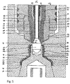
- the in the FIGS. 1 to 4 injection molding apparatus 11 shown for producing at least one tube head comprises a mold having a mold insert 13 and a nozzle 15 cooperating with the mold insert 13.
- the mold insert 13 and the nozzle 15 are received in a cavity of a mold block not shown in the figures.
- a plurality of such injection molding devices can be present next to one another in order to be able to produce a plurality of tube heads simultaneously in one work cycle.
- the injection molding devices are in known manner via distribution channels with one or more extruders in combination.
- the mold insert 13 has a recess 17 in which two movable sliding parts 19a, 19b are received in a form-fitting manner.
- the sliding parts 19a, 19b together form two mold halves whose inner contour 21 corresponds to the outer contour of a tube neck to be produced.
- the Innnenkontur 21 has helical grooves 23 which form the external thread of the tube neck.
- the mold insert 13 has a rear, immediately following the sliding parts 19a, 19b subsequent molding section 25, which images the negative of the outer contour of the tube shoulder to be produced.
- the mold portion 25 has a first cylindrical portion 27, a conical transition portion 29 and a second cylindrical portion 31 which adjoins the movable sliding parts 19a, 19b.
- the second cylindrical portion 31 serves to produce a tube collar, which is located between the tube neck and tube shoulder.
- the shape of a tube collar is not mandatory, but recommended from a manufacturing point of view, otherwise - due to the multi-part of the mold insert - a disturbing annular bead or at least a visible edge would be left.
- an axially movable core 33 is received in the mold section 25, an axially movable core 33 is received.
- the core 33 has an outer contour 35, which corresponds to the inner contour of the tube head to be produced.
- a mold cavity 37 is present, which is completely filled in the injection molding with a flowable plastic material.
- a so-called scraper 39 is provided.
- the scraper 39 forms with a ring portion 41, the front-side rear wall of the tube head.
- the sliding parts 19a, 19b are moved apart (arrow 43) and then the core with the scraper 39 is withdrawn in the axial direction (arrow 45).
- the finished tube head is withdrawn by the preferably movable scraper 39 from the stationary core 33 and falls in horizontal installation of the mold insert down.
- the nozzle 15 is arranged in a recess 47 of the mold insert 13. It comprises a nozzle body 49 with an axial passage 50, in which a valve needle 51 is arranged axially movable.
- the valve needle shaft 53 is surrounded by an axially movable valve sleeve 57, which has an inner diameter greater than the outer diameter of the valve needle shaft 53 and sealingly abut the valve needle head 55 with the front end 59.
- a first flow channel 63 for a first material component 64 and between the inner wall 65 of the valve sleeve 57 and the valve needle shaft 53, a second flow channel 67 for a second material component 68 are created.
- the valve needle head 55 has a cylindrical body 69, which forms a first valve for the first material component 64 in cooperation with a cylindrical portion 70 of the mold insert.
- an annular opening 72 is formed (see, eg FIG. 2 ), through which the melt at an angle, can escape radially outward.
- the preferred angle is between 30 and 90 degrees relative to the longitudinal axis of the device.
- a conical transition region 71 is provided between the cylindrical body 69 and the valve needle shaft 53.
- the front end 59 of the valve sleeve 57 is formed so that the distal end face 73 can abut surface on the cone 71 and so a second valve for the second material component 68 is formed.
- the transition region 71 may have a circumferential recess 75, so that the plastic melt is less resistive when injected into the mold cavity.
- the valve needle head 55 is received in the open position of the first valve in a cylindrical recess 77 which is provided in the nozzle-side end face of the core 33.
- the outer diameter of the cylindrical body 69 substantially corresponds to the inner diameter of the recess 77, so that only a small clearance of less than 20 micrometers, preferably less than 10 micrometers is present.
- the surface of the cylindrical portion of the valve pin head 55 may also be provided with annular recesses to reduce heat transfer from the valve pin head 55 to the recess 77 of the cooled core 33 (not shown in the figures).
- the valve pin head 55 may also be made of a poor thermal conductivity material to reduce unwanted heating of the core 33.
- annular gap 83 is formed, which serves as a gate. If the valve needle is moved from a retracted closed position ( Fig. 1 ) into an advanced open position ( Fig. 2 to 5 ), fluid communication is provided at least with the first flow channel 63 and the first material component can flow into the mold cavity 37.
- a substantially cylindrical sealing member 85 is provided with an external thread 87. This is screwed into a corresponding bore 89 with internal thread 91.
- the sealing part has a cylindrical portion 93 which is received in a form-fitting manner in a corresponding, cylindrical portion 95 of the mold insert 13.
- a heating device 101 is inserted in the outer jacket of the nozzle body.
- an air gap 103 is provided for the purpose of thermal insulation between the nozzle 15 and the mold insert 13.
- the structure material 64 is injected into the mold cavity, namely until it is filled up to approximately 70-85% by volume ( Fig. 7 ). Then the structure material is deposited and the barrier material 68 injected into the core of the structure material 64 ( Fig. 8 ). Since the latter has already solidified on the outer surfaces at the time when the injection of the barrier material begins, the barrier material in the core of the structural material can penetrate far towards the end face 41. At the end of the barrier material 68 is discontinued and injected a small amount of the structural material 64, so that the latter preferably completely encloses the barrier material ( Fig. 9 ).
- An injection molding apparatus for producing at least one tube head with a tube shoulder and neck formed with an ejection opening comprises a mold cavity defining a mold cavity 37 and a nozzle 15 cooperating with the mold.
- the nozzle 15 has a nozzle body 49 and a valve needle movable in the nozzle body 49 in the direction of the tube longitudinal axis 51. This consists of a valve needle shaft (53) and a terminal valve needle head 55th
- the valve needle 51 is surrounded by a first flow channel 63, through which a first material component 64 can be pressed out.
- the opening 72 of the nozzle is closed 15 of a retracted position of the valve needle 51 by the valve needle head 55 and released in an advanced position of the valve needle 51 through the valve needle head 55, wherein in the advanced position of the valve needle 51, an annular outlet opening 72 is formed, which with a serving as a gate opening annular gap 83 of the mold produces a fluid connection in the mold cavity 37.
Landscapes
- Engineering & Computer Science (AREA)
- Mechanical Engineering (AREA)
- Manufacturing & Machinery (AREA)
- Moulds For Moulding Plastics Or The Like (AREA)
- Injection Moulding Of Plastics Or The Like (AREA)
- Blow-Moulding Or Thermoforming Of Plastics Or The Like (AREA)
Priority Applications (1)
| Application Number | Priority Date | Filing Date | Title |
|---|---|---|---|
| PL17202178T PL3308933T3 (pl) | 2012-09-19 | 2013-09-17 | Urządzenie i sposób wytwarzania głowicy tuby |
Applications Claiming Priority (3)
| Application Number | Priority Date | Filing Date | Title |
|---|---|---|---|
| CH01696/12A CH706993A1 (en) | 2012-09-19 | 2012-09-19 | Injection molding apparatus and method for producing a tube head, and tube head. |
| PCT/EP2013/069192 WO2014044647A2 (fr) | 2012-09-19 | 2013-09-17 | Dispositif et procédé de fabrication d'une tête de tube, ainsi que tête de tube |
| EP13765980.1A EP2897779B1 (fr) | 2012-09-19 | 2013-09-17 | Dispositif de fabrication d'une tête de tube |
Related Parent Applications (2)
| Application Number | Title | Priority Date | Filing Date |
|---|---|---|---|
| EP13765980.1A Division EP2897779B1 (fr) | 2012-09-19 | 2013-09-17 | Dispositif de fabrication d'une tête de tube |
| EP13765980.1A Division-Into EP2897779B1 (fr) | 2012-09-19 | 2013-09-17 | Dispositif de fabrication d'une tête de tube |
Publications (2)
| Publication Number | Publication Date |
|---|---|
| EP3308933A1 true EP3308933A1 (fr) | 2018-04-18 |
| EP3308933B1 EP3308933B1 (fr) | 2020-08-12 |
Family
ID=46924177
Family Applications (2)
| Application Number | Title | Priority Date | Filing Date |
|---|---|---|---|
| EP13765980.1A Not-in-force EP2897779B1 (fr) | 2012-09-19 | 2013-09-17 | Dispositif de fabrication d'une tête de tube |
| EP17202178.4A Active EP3308933B1 (fr) | 2012-09-19 | 2013-09-17 | Dispositif et procédé de fabrication d'une tête de tube |
Family Applications Before (1)
| Application Number | Title | Priority Date | Filing Date |
|---|---|---|---|
| EP13765980.1A Not-in-force EP2897779B1 (fr) | 2012-09-19 | 2013-09-17 | Dispositif de fabrication d'une tête de tube |
Country Status (16)
| Country | Link |
|---|---|
| US (1) | US10040228B2 (fr) |
| EP (2) | EP2897779B1 (fr) |
| CN (2) | CN104661802B (fr) |
| AR (1) | AR092631A1 (fr) |
| BR (2) | BR112015005659B1 (fr) |
| CH (1) | CH706993A1 (fr) |
| ES (1) | ES2682765T3 (fr) |
| HR (1) | HRP20181397T1 (fr) |
| HU (1) | HUE039031T2 (fr) |
| MX (1) | MX362951B (fr) |
| PL (2) | PL2897779T3 (fr) |
| PT (1) | PT2897779T (fr) |
| RS (1) | RS57717B1 (fr) |
| RU (1) | RU2644470C2 (fr) |
| SI (1) | SI2897779T1 (fr) |
| WO (1) | WO2014044647A2 (fr) |
Families Citing this family (10)
| Publication number | Priority date | Publication date | Assignee | Title |
|---|---|---|---|---|
| US9221204B2 (en) * | 2013-03-14 | 2015-12-29 | Kortec, Inc. | Techniques to mold parts with injection-formed aperture in gate area |
| US9809370B2 (en) * | 2014-08-14 | 2017-11-07 | Scholle Ipn Corporation | Barrier spout for a flexible bag and a flexible bag having a barrier spout |
| US11685095B2 (en) | 2015-06-30 | 2023-06-27 | The Goodyear Tire & Rubber Company | Method and apparatus for forming tire components using a coextruded strip |
| CH712322A1 (de) | 2016-04-07 | 2017-10-13 | Fostag Formenbau Ag | Spritzgusswerkzeug. |
| ITUA20162984A1 (it) * | 2016-04-28 | 2017-10-28 | Friul Filiere Spa | Testa di estrusione di tubi |
| CN112372941B (zh) * | 2020-10-16 | 2022-04-19 | 新乡华青药业有限公司 | 一种自动化管状注肩设备及其制备的包装管 |
| CN112754453B (zh) * | 2021-01-25 | 2024-03-08 | 武汉中针智能科技有限公司 | 智能注射针头结构的、模具及制备方法 |
| CN114290607B (zh) * | 2021-11-25 | 2024-04-09 | 佛山市星科骏智能科技有限公司 | 一种塑胶软管注头生产设备 |
| CN114311498B (zh) * | 2021-11-25 | 2024-04-09 | 佛山市星科骏智能科技有限公司 | 一种塑胶软管注头生产方法 |
| CN114311545B (zh) * | 2021-12-31 | 2024-10-29 | 广东弗伦克模塑科技有限公司 | 一种能够精准控温的热咀机构 |
Citations (3)
| Publication number | Priority date | Publication date | Assignee | Title |
|---|---|---|---|---|
| JPH05131495A (ja) * | 1991-09-11 | 1993-05-28 | Showa Denko Kk | サンドイツチ射出成形法 |
| US20080258356A1 (en) * | 2007-04-19 | 2008-10-23 | Inbev S.A. | Integrally blow-moulded bag-in-container comprising an inner layer and an outer layer comprising energy absorbing additives, and preform for making it |
| US20110233824A1 (en) * | 2010-03-25 | 2011-09-29 | Valois Sas | Method of molding a hollow body of revolution |
Family Cites Families (31)
| Publication number | Priority date | Publication date | Assignee | Title |
|---|---|---|---|---|
| CH305197A (fr) * | 1953-01-08 | 1955-02-15 | Andre Strahm | Machine pour le moulage d'un objet en matière thermoplastique. |
| US4530654A (en) * | 1984-05-29 | 1985-07-23 | Mold-Masters Limited | Injection molding peripheral opening core ring gate |
| JPH05162174A (ja) * | 1991-12-13 | 1993-06-29 | Yoshida Kogyo Kk <Ykk> | チューブ容器の製造方法およびチューブ容器 |
| JP3107502B2 (ja) * | 1995-04-28 | 2000-11-13 | 池上金型工業株式会社 | 射出成形金型 |
| JPH09254192A (ja) * | 1996-03-26 | 1997-09-30 | Sekisui Chem Co Ltd | 射出成形金型 |
| US5785915A (en) * | 1996-09-13 | 1998-07-28 | Osuna-Diaz; Jesus M. | Injection molding with annular gate and sleeve shutoff valve |
| FR2784657B1 (fr) * | 1998-10-19 | 2000-11-17 | Cebal | Tube a tete en materiaux multicouches et procede de fabrication |
| CA2253042C (fr) * | 1998-11-05 | 2007-04-17 | Jobst Ulrich Gellert | Methode de moulage par injection a trois couches avec co-injection sequentielle et simultanee |
| PT1033318E (pt) | 1999-02-18 | 2003-02-28 | Foboha Gmbh | Ombro de bisnaga e procedimento para a sua fabricacao |
| US6440350B1 (en) * | 1999-03-18 | 2002-08-27 | Mold-Masters Limited | Apparatus and method for multi-layer injection molding |
| FR2806385B1 (fr) * | 2000-03-17 | 2002-12-06 | Cep Ind | Tube souple, resistant a la fissuration sous contrainte et impermeable a la vapeur d'eau |
| CA2317779A1 (fr) * | 2000-09-06 | 2002-03-06 | Mold-Masters Limited | Corps de vanne pour le moulage par injection |
| DE60328425D1 (de) * | 2002-12-03 | 2009-08-27 | Mold Masters 2007 Ltd | Heißkanal-Koinjektionsdüse |
| US6989124B2 (en) * | 2003-01-24 | 2006-01-24 | Husky Injection Molding Systems Ltd. | Apparatus and method for removing a molded article from a mold |
| EP1520796A1 (fr) * | 2003-09-30 | 2005-04-06 | Alcan Technology & Management Ltd. | Tube en matière plastique avec une couche intérieure et méthodes pour sa fabrication |
| DE102005009382A1 (de) * | 2005-03-01 | 2006-09-07 | Kunststoffwerk Kutterer Gmbh & Co. Kg | Tubenschultereinrichtung für Tuben, Tube, Verfahren zur Herstellung einer Tubenschultereinrichtung und Verfahren zur Herstellung einer Tube |
| US20070222111A1 (en) * | 2006-03-23 | 2007-09-27 | Owens-Illinois Healthcare Packaging Inc. | Apparatus and method for injection molding a multilayer container or container preform, or injection blow molding a multilayer container |
| US7527490B2 (en) * | 2006-10-13 | 2009-05-05 | Mold-Masters (2007) Limited | Coinjection molding apparatus and related hot-runner nozzle |
| WO2008125698A1 (fr) * | 2007-04-11 | 2008-10-23 | Molmasa Aplicaciones Técnicas, S.L. | Moule et procédé de fabrication de préformes bi-composant par surmoulage par injection et préforme bi-composant obtenue |
| US7513772B2 (en) * | 2007-05-09 | 2009-04-07 | Mold-Masters (2007) Limited | Injection molding nozzle with valve pin alignment |
| WO2009015411A1 (fr) * | 2007-07-29 | 2009-02-05 | Continuous Moulding Technologies Pty Ltd | Procédé de moulage d'objet de longueur indéfinie avec un appareil de moule par injection |
| FR2922807B1 (fr) * | 2007-10-26 | 2009-12-18 | Alcan Packaging Beauty Serv | Fabrication en grande cadence de pieces moulees par injection |
| DE102007059432A1 (de) * | 2007-12-10 | 2009-06-18 | Zhafir Plastics Machinery Gmbh | Kolbeneinspritzeinheit für eine Spritzgussmaschine |
| US8607999B2 (en) * | 2008-06-30 | 2013-12-17 | Yoshino Kogyosho Co., Ltd. | Laminated synthetic resin bottle, injection molding device, and process for molding a laminated preform |
| US20100044896A1 (en) * | 2008-08-21 | 2010-02-25 | Payman Tabassi | Injection Molding Apparatus Having a Nozzle Tip Component for Taking a Nozzle Out of Service |
| NL2005313C2 (en) * | 2010-09-03 | 2012-03-06 | Plasticum Group B V | Injection mould for flexible tube. |
| EP2618982B1 (fr) * | 2010-09-21 | 2018-10-31 | Mold-Masters (2007) Limited | Système de moulage par injection à canaux chauds de coinjection |
| JP2012232463A (ja) * | 2011-04-28 | 2012-11-29 | Yoshino Kogyosho Co Ltd | プリフォームの射出成形装置、射出成形方法及び合成樹脂製壜体 |
| KR101136553B1 (ko) * | 2011-06-24 | 2012-05-03 | 주식회사 엠엔에이치 | 세라믹 싱글밸브 시스템 |
| US9221204B2 (en) * | 2013-03-14 | 2015-12-29 | Kortec, Inc. | Techniques to mold parts with injection-formed aperture in gate area |
| JP5908445B2 (ja) * | 2013-09-17 | 2016-04-26 | 日精樹脂工業株式会社 | ホットランナーノズルと、このホットランナーノズルを取り付けた金型 |
-
2012
- 2012-09-19 CH CH01696/12A patent/CH706993A1/en not_active Application Discontinuation
-
2013
- 2013-09-17 RU RU2015114439A patent/RU2644470C2/ru active
- 2013-09-17 CN CN201380047206.3A patent/CN104661802B/zh not_active Expired - Fee Related
- 2013-09-17 CN CN201810971192.9A patent/CN109049505B/zh not_active Expired - Fee Related
- 2013-09-17 HR HRP20181397TT patent/HRP20181397T1/hr unknown
- 2013-09-17 PT PT137659801T patent/PT2897779T/pt unknown
- 2013-09-17 PL PL13765980T patent/PL2897779T3/pl unknown
- 2013-09-17 PL PL17202178T patent/PL3308933T3/pl unknown
- 2013-09-17 WO PCT/EP2013/069192 patent/WO2014044647A2/fr not_active Ceased
- 2013-09-17 MX MX2015003372A patent/MX362951B/es active IP Right Grant
- 2013-09-17 BR BR112015005659-8A patent/BR112015005659B1/pt not_active IP Right Cessation
- 2013-09-17 HU HUE13765980A patent/HUE039031T2/hu unknown
- 2013-09-17 BR BR122020013159-4A patent/BR122020013159B1/pt not_active IP Right Cessation
- 2013-09-17 US US14/429,686 patent/US10040228B2/en not_active Expired - Fee Related
- 2013-09-17 EP EP13765980.1A patent/EP2897779B1/fr not_active Not-in-force
- 2013-09-17 EP EP17202178.4A patent/EP3308933B1/fr active Active
- 2013-09-17 ES ES13765980.1T patent/ES2682765T3/es active Active
- 2013-09-17 SI SI201331146T patent/SI2897779T1/sl unknown
- 2013-09-17 RS RS20181017A patent/RS57717B1/sr unknown
- 2013-09-19 AR ARP130103371A patent/AR092631A1/es active IP Right Grant
Patent Citations (3)
| Publication number | Priority date | Publication date | Assignee | Title |
|---|---|---|---|---|
| JPH05131495A (ja) * | 1991-09-11 | 1993-05-28 | Showa Denko Kk | サンドイツチ射出成形法 |
| US20080258356A1 (en) * | 2007-04-19 | 2008-10-23 | Inbev S.A. | Integrally blow-moulded bag-in-container comprising an inner layer and an outer layer comprising energy absorbing additives, and preform for making it |
| US20110233824A1 (en) * | 2010-03-25 | 2011-09-29 | Valois Sas | Method of molding a hollow body of revolution |
Also Published As
| Publication number | Publication date |
|---|---|
| AR092631A1 (es) | 2015-04-29 |
| RU2015114439A (ru) | 2016-11-10 |
| SI2897779T1 (sl) | 2018-10-30 |
| HUE039031T2 (hu) | 2018-12-28 |
| US20150246468A1 (en) | 2015-09-03 |
| RS57717B1 (sr) | 2018-12-31 |
| EP3308933B1 (fr) | 2020-08-12 |
| BR112015005659A2 (pt) | 2017-07-04 |
| EP2897779B1 (fr) | 2018-05-30 |
| CN104661802B (zh) | 2018-11-06 |
| PL2897779T3 (pl) | 2018-11-30 |
| ES2682765T3 (es) | 2018-09-21 |
| HRP20181397T1 (hr) | 2018-11-02 |
| CN104661802A (zh) | 2015-05-27 |
| PL3308933T3 (pl) | 2021-03-08 |
| CH706993A1 (en) | 2014-03-31 |
| MX362951B (es) | 2019-02-27 |
| BR122020013159B1 (pt) | 2021-05-04 |
| US10040228B2 (en) | 2018-08-07 |
| CN109049505A (zh) | 2018-12-21 |
| PT2897779T (pt) | 2018-09-28 |
| WO2014044647A2 (fr) | 2014-03-27 |
| BR112015005659B1 (pt) | 2020-11-10 |
| RU2644470C2 (ru) | 2018-02-12 |
| EP2897779A2 (fr) | 2015-07-29 |
| WO2014044647A3 (fr) | 2014-05-15 |
| CN109049505B (zh) | 2020-09-29 |
| MX2015003372A (es) | 2015-08-12 |
Similar Documents
| Publication | Publication Date | Title |
|---|---|---|
| EP2897779B1 (fr) | Dispositif de fabrication d'une tête de tube | |
| DE60037449T2 (de) | Verbesserte mischvorrichtung und -verfahren für spritzgiessmaschinen | |
| DE3913109C2 (fr) | ||
| DE69008894T2 (de) | Spritzgusseinrichtung mit Gasdurchfluss durch die Ventilöffnung. | |
| EP0363948B1 (fr) | Buse pour machines de moulage par injection | |
| DE60209505T3 (de) | Verfahren zum spritzgiessen | |
| DE19848818A1 (de) | Fünflagen-Spritzgußvorrichtung mit vier Positionsventilbetätigungsmechanismen | |
| DE69228683T2 (de) | Düse für gasunterstütztes spritzgiessen | |
| DE4103318C2 (de) | Spritzkopf | |
| DE19848789A1 (de) | Spritzgußvorrichtung mit einer Schmelzbohrung durch das vordere Ende des Stiftes | |
| DE102013105435B3 (de) | Gießventil mit einem Nachverdichtungskolben | |
| EP2860010B1 (fr) | Dispositif et procédé de fabrication d'un élément de formage creux multicouche en plastique renforcé en fibres | |
| EP0435025B1 (fr) | Dispositif pour introduire un gaz dans la cavité d'un moule d'injection pour fabriquer des corps creux en matière plastique | |
| DE69823304T2 (de) | Spritzgiessvorrichtung mit Schmelzeübertragungs- und Aufteilungsbuchse | |
| DE2623308C3 (de) | Vorrichtung zum diskontinuierlichen Herstellen von Formteilen aus thermoplastischem Kunststoff | |
| EP0668140B1 (fr) | Procédé pour fabriquer des brosses à dents | |
| DE1479381A1 (de) | Verfahren und Vorrichtung zum Herstellen von Hohlkoerpern aus thermoplastischem Material | |
| EP3609672B1 (fr) | Connecteur enfichable en matière plastique et procédé de fabrication associé | |
| DE4032500C2 (de) | Verfahren zur Herstellung eines Mehrkomponenten-Spritzgießteiles und Mehrfachform-Spritzgießeinrichtung | |
| DE102006004928A1 (de) | Verbesserte Halsbackenkühlung | |
| DE102005050360A1 (de) | Spritzgiessvorrichtung mit Seitenanguss | |
| WO2017174357A1 (fr) | Outil de moulage par injection | |
| DE102016201584A1 (de) | Verfahren zur Anordnung einer Dichtungsformation an einem Bauteil und Extrusionsvorrichtung hierfür | |
| DE19713874B4 (de) | Vorrichtung zur Einleitung von Gas in ein Formwerkzeug | |
| DE3341228C2 (de) | Formwerkzeug für einen Behälter-Kopfteil aus Kunststoff |
Legal Events
| Date | Code | Title | Description |
|---|---|---|---|
| PUAI | Public reference made under article 153(3) epc to a published international application that has entered the european phase |
Free format text: ORIGINAL CODE: 0009012 |
|
| STAA | Information on the status of an ep patent application or granted ep patent |
Free format text: STATUS: THE APPLICATION HAS BEEN PUBLISHED |
|
| AC | Divisional application: reference to earlier application |
Ref document number: 2897779 Country of ref document: EP Kind code of ref document: P |
|
| AK | Designated contracting states |
Kind code of ref document: A1 Designated state(s): AL AT BE BG CH CY CZ DE DK EE ES FI FR GB GR HR HU IE IS IT LI LT LU LV MC MK MT NL NO PL PT RO RS SE SI SK SM TR |
|
| STAA | Information on the status of an ep patent application or granted ep patent |
Free format text: STATUS: REQUEST FOR EXAMINATION WAS MADE |
|
| 17P | Request for examination filed |
Effective date: 20181018 |
|
| RIC1 | Information provided on ipc code assigned before grant |
Ipc: B29C 45/28 20060101AFI20191008BHEP Ipc: B29C 45/16 20060101ALI20191008BHEP Ipc: B65D 35/12 20060101ALN20191008BHEP |
|
| RIC1 | Information provided on ipc code assigned before grant |
Ipc: B29C 45/16 20060101ALI20191024BHEP Ipc: B65D 35/12 20060101ALN20191024BHEP Ipc: B29C 45/28 20060101AFI20191024BHEP |
|
| GRAP | Despatch of communication of intention to grant a patent |
Free format text: ORIGINAL CODE: EPIDOSNIGR1 |
|
| RIC1 | Information provided on ipc code assigned before grant |
Ipc: B29C 45/16 20060101ALI20191028BHEP Ipc: B65D 35/12 20060101ALN20191028BHEP Ipc: B29C 45/28 20060101AFI20191028BHEP |
|
| STAA | Information on the status of an ep patent application or granted ep patent |
Free format text: STATUS: GRANT OF PATENT IS INTENDED |
|
| RIC1 | Information provided on ipc code assigned before grant |
Ipc: B65D 35/12 20060101ALN20191113BHEP Ipc: B29C 45/16 20060101ALI20191113BHEP Ipc: B29C 45/28 20060101AFI20191113BHEP |
|
| RIC1 | Information provided on ipc code assigned before grant |
Ipc: B65D 35/12 20060101ALN20191119BHEP Ipc: B29C 45/16 20060101ALI20191119BHEP Ipc: B29C 45/28 20060101AFI20191119BHEP |
|
| INTG | Intention to grant announced |
Effective date: 20191205 |
|
| GRAJ | Information related to disapproval of communication of intention to grant by the applicant or resumption of examination proceedings by the epo deleted |
Free format text: ORIGINAL CODE: EPIDOSDIGR1 |
|
| STAA | Information on the status of an ep patent application or granted ep patent |
Free format text: STATUS: REQUEST FOR EXAMINATION WAS MADE |
|
| GRAP | Despatch of communication of intention to grant a patent |
Free format text: ORIGINAL CODE: EPIDOSNIGR1 |
|
| STAA | Information on the status of an ep patent application or granted ep patent |
Free format text: STATUS: GRANT OF PATENT IS INTENDED |
|
| INTC | Intention to grant announced (deleted) | ||
| INTG | Intention to grant announced |
Effective date: 20200408 |
|
| RIC1 | Information provided on ipc code assigned before grant |
Ipc: B29C 45/28 20060101AFI20200330BHEP Ipc: B29C 45/16 20060101ALI20200330BHEP Ipc: B65D 35/12 20060101ALN20200330BHEP |
|
| GRAS | Grant fee paid |
Free format text: ORIGINAL CODE: EPIDOSNIGR3 |
|
| GRAA | (expected) grant |
Free format text: ORIGINAL CODE: 0009210 |
|
| STAA | Information on the status of an ep patent application or granted ep patent |
Free format text: STATUS: THE PATENT HAS BEEN GRANTED |
|
| AC | Divisional application: reference to earlier application |
Ref document number: 2897779 Country of ref document: EP Kind code of ref document: P |
|
| AK | Designated contracting states |
Kind code of ref document: B1 Designated state(s): AL AT BE BG CH CY CZ DE DK EE ES FI FR GB GR HR HU IE IS IT LI LT LU LV MC MK MT NL NO PL PT RO RS SE SI SK SM TR |
|
| REG | Reference to a national code |
Ref country code: CH Ref legal event code: EP |
|
| REG | Reference to a national code |
Ref country code: IE Ref legal event code: FG4D Free format text: LANGUAGE OF EP DOCUMENT: GERMAN |
|
| REG | Reference to a national code |
Ref country code: DE Ref legal event code: R096 Ref document number: 502013015025 Country of ref document: DE |
|
| REG | Reference to a national code |
Ref country code: AT Ref legal event code: REF Ref document number: 1301125 Country of ref document: AT Kind code of ref document: T Effective date: 20200915 |
|
| REG | Reference to a national code |
Ref country code: LT Ref legal event code: MG4D |
|
| REG | Reference to a national code |
Ref country code: GR Ref legal event code: EP Ref document number: 20200403010 Country of ref document: GR Effective date: 20201215 |
|
| REG | Reference to a national code |
Ref country code: NL Ref legal event code: MP Effective date: 20200812 |
|
| PG25 | Lapsed in a contracting state [announced via postgrant information from national office to epo] |
Ref country code: HR Free format text: LAPSE BECAUSE OF FAILURE TO SUBMIT A TRANSLATION OF THE DESCRIPTION OR TO PAY THE FEE WITHIN THE PRESCRIBED TIME-LIMIT Effective date: 20200812 Ref country code: LT Free format text: LAPSE BECAUSE OF FAILURE TO SUBMIT A TRANSLATION OF THE DESCRIPTION OR TO PAY THE FEE WITHIN THE PRESCRIBED TIME-LIMIT Effective date: 20200812 Ref country code: BG Free format text: LAPSE BECAUSE OF FAILURE TO SUBMIT A TRANSLATION OF THE DESCRIPTION OR TO PAY THE FEE WITHIN THE PRESCRIBED TIME-LIMIT Effective date: 20201112 Ref country code: SE Free format text: LAPSE BECAUSE OF FAILURE TO SUBMIT A TRANSLATION OF THE DESCRIPTION OR TO PAY THE FEE WITHIN THE PRESCRIBED TIME-LIMIT Effective date: 20200812 Ref country code: FI Free format text: LAPSE BECAUSE OF FAILURE TO SUBMIT A TRANSLATION OF THE DESCRIPTION OR TO PAY THE FEE WITHIN THE PRESCRIBED TIME-LIMIT Effective date: 20200812 Ref country code: NO Free format text: LAPSE BECAUSE OF FAILURE TO SUBMIT A TRANSLATION OF THE DESCRIPTION OR TO PAY THE FEE WITHIN THE PRESCRIBED TIME-LIMIT Effective date: 20201112 |
|
| PGFP | Annual fee paid to national office [announced via postgrant information from national office to epo] |
Ref country code: IT Payment date: 20201030 Year of fee payment: 8 Ref country code: GR Payment date: 20201030 Year of fee payment: 8 Ref country code: AT Payment date: 20201022 Year of fee payment: 8 Ref country code: CZ Payment date: 20201012 Year of fee payment: 8 |
|
| PG25 | Lapsed in a contracting state [announced via postgrant information from national office to epo] |
Ref country code: NL Free format text: LAPSE BECAUSE OF FAILURE TO SUBMIT A TRANSLATION OF THE DESCRIPTION OR TO PAY THE FEE WITHIN THE PRESCRIBED TIME-LIMIT Effective date: 20200812 Ref country code: LV Free format text: LAPSE BECAUSE OF FAILURE TO SUBMIT A TRANSLATION OF THE DESCRIPTION OR TO PAY THE FEE WITHIN THE PRESCRIBED TIME-LIMIT Effective date: 20200812 Ref country code: RS Free format text: LAPSE BECAUSE OF FAILURE TO SUBMIT A TRANSLATION OF THE DESCRIPTION OR TO PAY THE FEE WITHIN THE PRESCRIBED TIME-LIMIT Effective date: 20200812 Ref country code: IS Free format text: LAPSE BECAUSE OF FAILURE TO SUBMIT A TRANSLATION OF THE DESCRIPTION OR TO PAY THE FEE WITHIN THE PRESCRIBED TIME-LIMIT Effective date: 20201212 |
|
| PG25 | Lapsed in a contracting state [announced via postgrant information from national office to epo] |
Ref country code: SM Free format text: LAPSE BECAUSE OF FAILURE TO SUBMIT A TRANSLATION OF THE DESCRIPTION OR TO PAY THE FEE WITHIN THE PRESCRIBED TIME-LIMIT Effective date: 20200812 Ref country code: EE Free format text: LAPSE BECAUSE OF FAILURE TO SUBMIT A TRANSLATION OF THE DESCRIPTION OR TO PAY THE FEE WITHIN THE PRESCRIBED TIME-LIMIT Effective date: 20200812 Ref country code: RO Free format text: LAPSE BECAUSE OF FAILURE TO SUBMIT A TRANSLATION OF THE DESCRIPTION OR TO PAY THE FEE WITHIN THE PRESCRIBED TIME-LIMIT Effective date: 20200812 Ref country code: DK Free format text: LAPSE BECAUSE OF FAILURE TO SUBMIT A TRANSLATION OF THE DESCRIPTION OR TO PAY THE FEE WITHIN THE PRESCRIBED TIME-LIMIT Effective date: 20200812 |
|
| REG | Reference to a national code |
Ref country code: CH Ref legal event code: PL |
|
| REG | Reference to a national code |
Ref country code: DE Ref legal event code: R097 Ref document number: 502013015025 Country of ref document: DE |
|
| PG25 | Lapsed in a contracting state [announced via postgrant information from national office to epo] |
Ref country code: ES Free format text: LAPSE BECAUSE OF FAILURE TO SUBMIT A TRANSLATION OF THE DESCRIPTION OR TO PAY THE FEE WITHIN THE PRESCRIBED TIME-LIMIT Effective date: 20200812 Ref country code: AL Free format text: LAPSE BECAUSE OF FAILURE TO SUBMIT A TRANSLATION OF THE DESCRIPTION OR TO PAY THE FEE WITHIN THE PRESCRIBED TIME-LIMIT Effective date: 20200812 Ref country code: MC Free format text: LAPSE BECAUSE OF FAILURE TO SUBMIT A TRANSLATION OF THE DESCRIPTION OR TO PAY THE FEE WITHIN THE PRESCRIBED TIME-LIMIT Effective date: 20200812 |
|
| PGFP | Annual fee paid to national office [announced via postgrant information from national office to epo] |
Ref country code: PL Payment date: 20201012 Year of fee payment: 8 |
|
| PLBE | No opposition filed within time limit |
Free format text: ORIGINAL CODE: 0009261 |
|
| REG | Reference to a national code |
Ref country code: BE Ref legal event code: MM Effective date: 20200930 |
|
| STAA | Information on the status of an ep patent application or granted ep patent |
Free format text: STATUS: NO OPPOSITION FILED WITHIN TIME LIMIT |
|
| PG25 | Lapsed in a contracting state [announced via postgrant information from national office to epo] |
Ref country code: SK Free format text: LAPSE BECAUSE OF FAILURE TO SUBMIT A TRANSLATION OF THE DESCRIPTION OR TO PAY THE FEE WITHIN THE PRESCRIBED TIME-LIMIT Effective date: 20200812 Ref country code: LU Free format text: LAPSE BECAUSE OF NON-PAYMENT OF DUE FEES Effective date: 20200917 |
|
| 26N | No opposition filed |
Effective date: 20210514 |
|
| PG25 | Lapsed in a contracting state [announced via postgrant information from national office to epo] |
Ref country code: SI Free format text: LAPSE BECAUSE OF FAILURE TO SUBMIT A TRANSLATION OF THE DESCRIPTION OR TO PAY THE FEE WITHIN THE PRESCRIBED TIME-LIMIT Effective date: 20200812 Ref country code: IE Free format text: LAPSE BECAUSE OF NON-PAYMENT OF DUE FEES Effective date: 20200917 Ref country code: LI Free format text: LAPSE BECAUSE OF NON-PAYMENT OF DUE FEES Effective date: 20200930 Ref country code: BE Free format text: LAPSE BECAUSE OF NON-PAYMENT OF DUE FEES Effective date: 20200930 Ref country code: CH Free format text: LAPSE BECAUSE OF NON-PAYMENT OF DUE FEES Effective date: 20200930 |
|
| PGFP | Annual fee paid to national office [announced via postgrant information from national office to epo] |
Ref country code: FR Payment date: 20210927 Year of fee payment: 9 |
|
| PGFP | Annual fee paid to national office [announced via postgrant information from national office to epo] |
Ref country code: GB Payment date: 20210923 Year of fee payment: 9 Ref country code: DE Payment date: 20210921 Year of fee payment: 9 |
|
| REG | Reference to a national code |
Ref country code: AT Ref legal event code: MM01 Ref document number: 1301125 Country of ref document: AT Kind code of ref document: T Effective date: 20210917 |
|
| PG25 | Lapsed in a contracting state [announced via postgrant information from national office to epo] |
Ref country code: TR Free format text: LAPSE BECAUSE OF FAILURE TO SUBMIT A TRANSLATION OF THE DESCRIPTION OR TO PAY THE FEE WITHIN THE PRESCRIBED TIME-LIMIT Effective date: 20200812 Ref country code: MT Free format text: LAPSE BECAUSE OF FAILURE TO SUBMIT A TRANSLATION OF THE DESCRIPTION OR TO PAY THE FEE WITHIN THE PRESCRIBED TIME-LIMIT Effective date: 20200812 Ref country code: CZ Free format text: LAPSE BECAUSE OF NON-PAYMENT OF DUE FEES Effective date: 20210917 Ref country code: CY Free format text: LAPSE BECAUSE OF FAILURE TO SUBMIT A TRANSLATION OF THE DESCRIPTION OR TO PAY THE FEE WITHIN THE PRESCRIBED TIME-LIMIT Effective date: 20200812 |
|
| PG25 | Lapsed in a contracting state [announced via postgrant information from national office to epo] |
Ref country code: MK Free format text: LAPSE BECAUSE OF FAILURE TO SUBMIT A TRANSLATION OF THE DESCRIPTION OR TO PAY THE FEE WITHIN THE PRESCRIBED TIME-LIMIT Effective date: 20200812 |
|
| PG25 | Lapsed in a contracting state [announced via postgrant information from national office to epo] |
Ref country code: PT Free format text: LAPSE BECAUSE OF FAILURE TO SUBMIT A TRANSLATION OF THE DESCRIPTION OR TO PAY THE FEE WITHIN THE PRESCRIBED TIME-LIMIT Effective date: 20200812 |
|
| PG25 | Lapsed in a contracting state [announced via postgrant information from national office to epo] |
Ref country code: GR Free format text: LAPSE BECAUSE OF NON-PAYMENT OF DUE FEES Effective date: 20220407 Ref country code: AT Free format text: LAPSE BECAUSE OF NON-PAYMENT OF DUE FEES Effective date: 20210917 |
|
| PG25 | Lapsed in a contracting state [announced via postgrant information from national office to epo] |
Ref country code: IT Free format text: LAPSE BECAUSE OF NON-PAYMENT OF DUE FEES Effective date: 20210917 |
|
| REG | Reference to a national code |
Ref country code: DE Ref legal event code: R119 Ref document number: 502013015025 Country of ref document: DE |
|
| GBPC | Gb: european patent ceased through non-payment of renewal fee |
Effective date: 20220917 |
|
| PG25 | Lapsed in a contracting state [announced via postgrant information from national office to epo] |
Ref country code: PL Free format text: LAPSE BECAUSE OF NON-PAYMENT OF DUE FEES Effective date: 20210917 |
|
| PG25 | Lapsed in a contracting state [announced via postgrant information from national office to epo] |
Ref country code: FR Free format text: LAPSE BECAUSE OF NON-PAYMENT OF DUE FEES Effective date: 20220930 Ref country code: DE Free format text: LAPSE BECAUSE OF NON-PAYMENT OF DUE FEES Effective date: 20230401 |
|
| PG25 | Lapsed in a contracting state [announced via postgrant information from national office to epo] |
Ref country code: GB Free format text: LAPSE BECAUSE OF NON-PAYMENT OF DUE FEES Effective date: 20220917 |