EP3309385A1 - Injektorbecher, federklammer, flüssigkeitsinjektionsanordnung und verfahren zur anordnung davon - Google Patents
Injektorbecher, federklammer, flüssigkeitsinjektionsanordnung und verfahren zur anordnung davon Download PDFInfo
- Publication number
- EP3309385A1 EP3309385A1 EP16193477.3A EP16193477A EP3309385A1 EP 3309385 A1 EP3309385 A1 EP 3309385A1 EP 16193477 A EP16193477 A EP 16193477A EP 3309385 A1 EP3309385 A1 EP 3309385A1
- Authority
- EP
- European Patent Office
- Prior art keywords
- cup
- injector
- reference plane
- extends
- wings
- Prior art date
- Legal status (The legal status is an assumption and is not a legal conclusion. Google has not performed a legal analysis and makes no representation as to the accuracy of the status listed.)
- Granted
Links
Images


Classifications
-
- F—MECHANICAL ENGINEERING; LIGHTING; HEATING; WEAPONS; BLASTING
- F02—COMBUSTION ENGINES; HOT-GAS OR COMBUSTION-PRODUCT ENGINE PLANTS
- F02M—SUPPLYING COMBUSTION ENGINES IN GENERAL WITH COMBUSTIBLE MIXTURES OR CONSTITUENTS THEREOF
- F02M61/00—Fuel-injectors not provided for in groups F02M39/00 - F02M57/00 or F02M67/00
- F02M61/14—Arrangements of injectors with respect to engines; Mounting of injectors
-
- F—MECHANICAL ENGINEERING; LIGHTING; HEATING; WEAPONS; BLASTING
- F02—COMBUSTION ENGINES; HOT-GAS OR COMBUSTION-PRODUCT ENGINE PLANTS
- F02M—SUPPLYING COMBUSTION ENGINES IN GENERAL WITH COMBUSTIBLE MIXTURES OR CONSTITUENTS THEREOF
- F02M61/00—Fuel-injectors not provided for in groups F02M39/00 - F02M57/00 or F02M67/00
- F02M61/16—Details not provided for in, or of interest apart from, the apparatus of groups F02M61/02 - F02M61/14
- F02M61/168—Assembling; Disassembling; Manufacturing; Adjusting
-
- F—MECHANICAL ENGINEERING; LIGHTING; HEATING; WEAPONS; BLASTING
- F02—COMBUSTION ENGINES; HOT-GAS OR COMBUSTION-PRODUCT ENGINE PLANTS
- F02M—SUPPLYING COMBUSTION ENGINES IN GENERAL WITH COMBUSTIBLE MIXTURES OR CONSTITUENTS THEREOF
- F02M2200/00—Details of fuel-injection apparatus, not otherwise provided for
- F02M2200/16—Sealing of fuel injection apparatus not otherwise provided for
-
- F—MECHANICAL ENGINEERING; LIGHTING; HEATING; WEAPONS; BLASTING
- F02—COMBUSTION ENGINES; HOT-GAS OR COMBUSTION-PRODUCT ENGINE PLANTS
- F02M—SUPPLYING COMBUSTION ENGINES IN GENERAL WITH COMBUSTIBLE MIXTURES OR CONSTITUENTS THEREOF
- F02M2200/00—Details of fuel-injection apparatus, not otherwise provided for
- F02M2200/80—Fuel injection apparatus manufacture, repair or assembly
- F02M2200/8023—Fuel injection apparatus manufacture, repair or assembly the assembly involving use of quick-acting mechanisms, e.g. clips
-
- F—MECHANICAL ENGINEERING; LIGHTING; HEATING; WEAPONS; BLASTING
- F02—COMBUSTION ENGINES; HOT-GAS OR COMBUSTION-PRODUCT ENGINE PLANTS
- F02M—SUPPLYING COMBUSTION ENGINES IN GENERAL WITH COMBUSTIBLE MIXTURES OR CONSTITUENTS THEREOF
- F02M2200/00—Details of fuel-injection apparatus, not otherwise provided for
- F02M2200/85—Mounting of fuel injection apparatus
- F02M2200/853—Mounting of fuel injection apparatus involving use of quick-acting mechanism, e.g. clips
-
- F—MECHANICAL ENGINEERING; LIGHTING; HEATING; WEAPONS; BLASTING
- F02—COMBUSTION ENGINES; HOT-GAS OR COMBUSTION-PRODUCT ENGINE PLANTS
- F02M—SUPPLYING COMBUSTION ENGINES IN GENERAL WITH COMBUSTIBLE MIXTURES OR CONSTITUENTS THEREOF
- F02M2200/00—Details of fuel-injection apparatus, not otherwise provided for
- F02M2200/85—Mounting of fuel injection apparatus
- F02M2200/856—Mounting of fuel injection apparatus characterised by mounting injector to fuel or common rail, or vice versa
Definitions
- the present invention relates to an injector cup for a fluid injection assembly for an internal combustion engine, wherein the injector cup comprises:
- the present invention relates to a spring clip for a fluid injection assembly for an internal combustion engine, wherein the spring clip comprises:
- the present invention relates to a fluid injection assembly for an internal combustion engine, wherein the fluid injection assembly extends along a central longitudinal axis and comprises: an injector, comprising an injector tube and an injector body which is fixed to said injector tube, an injector cup and a spring clip.
- the present invention relates to a method for assembling a fluid injection assembly for a combustion engine, comprising the steps:
- Injection valve assemblies are in widespread use, in particular for internal combustion engines where they may be arranged in order to dose a fluid to a cylinder.
- a high pressure injector needs to be clamped on the cylinder head to ensure a correct position of its tip inside the combustion chamber.
- the orientation of the high pressure fuel injector with respect to the combustion chamber must be guaranteed to reach desired engine performances. This function is needed in order to control in an accurate way the fuel spray targeting inside the combustion chamber. Uncontrolled tip or spray position would have a negative impact on engine emission and performances.
- the injector cups which are connected to the fuel rail are fixed to the cylinder head for example by screws, clamps or the like in an intended relative position. It is known that at each injector its fluid inlet end is sealingly inserted into a cavity of a respective injector cup and to hold the respective injector at its injector cup by means of a spring clip.
- the injector under operation conditions can slightly move along its longitudinal direction relative to its injector cup whereas any inclination of the injector relative to the injector cup has to be avoided.
- An inclination of the injector may result in an unintended dismounting of the injector in particular during handling and transportation, but also during assembly if no appropriate provisions are made against this risk.
- an injector cup 1' for a fluid injection assembly of an internal combustion engine, wherein the injector cup 1 comprises a cup body 2' and a cup ring element 3'.
- the cup body 2' extends along a central longitudinal axis A' from a first axial end 4' to a second axial end 5' and the cup ring element 3' adjoins the border of the second axial end 5' by radially extending beyond said border 6'.
- a base surface 7' of the cup ring element 3' faces away from the first axial end 4' and defines a cup reference plane 8' which extends orthogonally to the longitudinal axis A'.
- the injector cup 1' is fixed to a fuel rail 9' by intermediate means 10'.
- a so-called stiffener 11' which is a bended sheetmetal part, is brazed to the injector cup 1' with the double aim of minimizing an injector spring clip inclination and an injector spring clip axial movement, thanks to the locally increased thickness given by the contribute of the two brazed sheet-metal components, i.e. the injector cup in the stiffener.
- a spring clip (which is not shown in Fig. 13 ) can be connected to the injector (also not shown in Fig. 13 ). So the problem of the movement of the injector would imply a risk of loosening the injector during transportation and mounting problems could arise during the assembly in the engine head.
- it is intended to provide an injector cup which can contribute to a reduction of an inclination of an injector mounted with said injector cup by a spring clip without the need of fixing a separate stiffener to the injector cup.
- the cup ring element comprises two wings.
- Each wing has a free end section which extends bent away from the cup reference plane at the side of the cup reference plane which faces towards the cup body, i.e. which faces in particular towards the first axial end.
- the two wings are spaced from each other and wherein a through opening is provided in the cup ring element between the two wings.
- the first axial end may be a fuel inlet end of the injector cup.
- the two wings may be designed by simply cutting and bending so that it is ensured that arms of a spring clip, which may be used for mounting a fuel injector to the injector cup, are in contact with the injector cup also in case of an injector inclination, avoiding as an advantage the risk of a loosening of the injector from the injector cup, for example during transport or handling.
- the through opening may extend through the cup ring element in a direction perpendicular to the cup reference plane.
- the two wings may be spaced from each other in a lateral direction which extends parallel to the cup reference plane and transversally or orthogonally to a direction which extends radially with respect to the longitudinal axis.
- the injector cup is a fuel rail injector cup, i.e. an injector cup which is capable or in particular adapted to be mounted to a fuel rail.
- the wings may be formed by a first step of cutting in the cup ring element a cut line or a recess having a shape like a T-profile extending along the cup reference plane in order to create the two wings each having an end face wherein both end faces face each other, and by a subsequent step of bending the end section of each wing away from the cup reference plane.
- each end face adjoins its neighboring front side face at an edge, wherein the edge has a length in a range of some millimeters and/or wherein the end face in a direction parallel to this edge has a length in a range of some millimeters.
- each of the fork arms at its respective one end is connected to the connecting portion and extends from the connecting portion towards its respective other end away from the clip reference plane, that each of the fork arms at its respective side which faces away from the respective other fork arm comprises a projection which is spaced from the connecting portion and which is directed away from the respective other fork arm and that at least one of the fork arms or each of the fork arms is deflectable elastically towards the respective other fork arm.
- the spring clip may be adapted to be used for mounting a fluid injector for an internal combustion engine to an injector cup, in particular to an injector cup of a fuel rail for an internal combustion engine.
- the first direction is orthogonally or inclined with respect to the symmetry plane and that the second direction is inclined with respect to the symmetry plane.
- the spring clip consists of metal or includes metal, preferably having incisive elastic properties.
- the injector cup is an injector cup according to one or more of the embodiments describe above and that the spring clip is a spring clip in accordance with one of the embodiments described above.
- the fluid injection assembly is adapted to be connected to a fuel rail.
- the injector body may be overmolded to the injector tube.
- the function of the two wings of the injector cup is to block the fork arms of the spring clip in order to avoid a kind of movement of the injector which could result in the risk of loosening the injector and accordingly in order to solve respective problems which may occur for example during transportation and during assembly.
- each of the flat sections of the spring clip may have an edge section facing toward the respective other flat section which may be shaped concavely so that in an undeformed state of the spring a minimum lateral distance between these edge sections is less compared to an outer diameter of a longitudinal section of the injector tube which is determined to be encompassed by the flat sections.
- the legs may be deflected somewhat laterally in an outward direction so that its minimum lateral distance exceeds the mentioned diameter of the injector tube and so that inserting of the flat sections in the slit is possible.
- the spring clip may be attached to the injector tube by a lateral snap fit connection so that it is not possible to lose the spring clip after mounting.
- a fluid inlet end of the injector is sealingly inserted into a cavity of the injector cup, that each projection comprises a tip wherein the tips are arranged in a lateral tip distance from each other, that between the wings a clearance is provided which is less compared to the lateral tip distance, that the arms extend through the clearance between the wings, wherein the one of the projections, in particular at its first surface, is in contact to the one of the wings and the other of the projections, in particular at its first surface, is in contact to the other of the wings.
- the function is to block the fork arms of the clip spring.
- the wings of the injector which may be formed by double bending, also a tilting of the injector with respect to a central longitudinal axis, which can cause disassembling during handling and transport, is limited, in particular thanks to tracks formed by the two bended wings as described before.
- the shape of the wings, in particular their length and width, and/or the shape of the arms, in particular their lengths and shapes of their projections, may be designed and determined in order to guarantee that projections of the arms are in contact with the injector cup also in case of an injector inclination, avoiding as an advantage the risk of a loosening of the injector from the injector cup, for example during transport or handling.
- each of the curved sections of the spring clip comprises a respective free end section, wherein both free end sections are hold or even pressed against the base surface of the cup ring element due to an elastic compression of the curved sections.
- This can be achieved by determining a length of the arms which is appropriate for this purpose.
- the spring clip exerts an elastic spring force in the direction of the longitudinal axis such that the injector body and the injector cup are pushed away from each other.
- the injector cup On mounting the fluid injection assembly to a housing of a combustion engine the injector cup may be fixed at the housing in a determined distance from it so that the clip spring may press the injector against the housing towards a cylinder on exerting an intended force.
- the injection body consists of or includes plastic material and/or is integrally formed (i.e. formed as a single piece).
- the injection body has been produced by overmolding to the injector tube.
- the injector body comprises a radially extending protrusion having a protrusion width with respect to a circumferential direction, that adjacent to the connecting portion the angle sections 25 have a lateral clearance between them which has a lateral width which is slightly bigger or equal compared to the protrusion width and that the protrusion extends into the lateral clearance between the fork arms so that the protrusion and the fork arms provide a form fit for blocking a rotation relative to each other around the central longitudinal axis.
- the protrusion and the lateral clearance act together for an indexing (anti-rotation) function whereby the protrusion provides a rotational stop with respect to the arms of the spring clip.
- the injector cup is an injector cup according to one or more of claims 1 - 5
- the spring clip is a spring clip according to one or more of claims 6 - 9
- the flat sections of the legs are inserted into the slit so that the flat sections encompass the injector tube and in particular so that the protrusion extends into the lateral clearance between the angled sections of the legs, and subsequently a fluid inlet end of the injector is axially inserted into a cavity of the injector cup by passing the fork arms of the spring clip through the clearance between the wings so that the fork arms starting from an undeformed shape at first are deflected towards each other until the protrusions extend beyond the wings so that the fork arms elastically spring back away from each other.
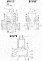
- FIG. 1 and Figs. 4-12 A preferred embodiment of an injector cup 1 in accordance to the invention is shown by Fig. 1 and Figs. 4-12 . It comprises a cup body 2 and a cup ring element 3.
- the cup body 2 extends along a central longitudinal axis A of the injector cup 1 from a first axial end 4 to a second axial end 5.
- the cup ring element 3 adjoins a border 6 of the second axial end 5 by radially extending beyond said border 6.
- a base surface 7 of the cup ring element 3 faces away from the cup body 2 and defines a cup reference plane 8. Said plane extends orthogonally with respect to the longitudinal axis A.
- the cup ring element 3 comprises two wings 12. The wings 12 as well as its respective details are indicated by corresponding reference signs.
- Each wing 12 has a first end section which is integrally connected to the adjoining flat wall 15 of the cup ring element 3. Further, antipodal to the first end each wing 12 has a respective free end section 13 which extends bent away from the cup reference plane 8 at the side of the cup reference plane 8 which is towards the cup body 2. Both wings 12 are spaced from each other by a through opening 14 which extends through the cup ring element 3 in a direction perpendicular to the cup reference plane 8.
- Each wing 12 comprises an end face 16 which extends parallel or slightly inclined to the cup reference plane 8. Further, each wing 12 has a front side face 17 which extends relative to the cup reference plane 8 angled by a bending angle ⁇ which in the example of Fig. 5 is 90 degree. Both front side faces 17 face towards each other. Both wings 12 are formed mirror symmetrically to each other with respect to a symmetry plane S (see also Fig. 5 ) . Because the bending angle ⁇ is 90 degree in the example, the end sections 13 of the wings extend orthogonally with respect to the cup reference plane 8. In the example the wings 12 are formed by a first step of cutting in the cup ring element 3 a recess which has a shape like a T-profile before bending of the wings 12 is performed. Before performing the bending both end faces 16 face to each other. After forming the cut the end sections 13 of the wings 12 have been bent away from the cup reference plane 8 in a subsequent step.
- Each end face 16 adjoins its neighboring front side face 17 at an edge 19 which as well as both adjoining faces 16, 17 have a length of some millimeters with respect to a direction which is parallel to the symmetry plane S.
- the injector cup 1 is integrally formed, i.e. formed as a single piece.
- FIGs 1, 3 and 5-12 show a preferred embodiment of a spring clip 20 in accordance to the invention. It comprises two legs 21 extending alongside and spaced from each other. Further, the spring clip 20 comprises two fork arms 22 and a connecting portion 23. The fork arms 22 extend alongside and spaced from each other. Each of the legs 21 has a curved section 24, an angled section 25 and a flat section 26 formed therebetween. Each of the flat sections has a base surface 27 (see Fig. 7 ) which extends along a clip reference plane 28. At the side of the clip reference plane 28 which faces away from the base surfaces 27 each of the curved sections 24 extends away from the clip reference plane 28 due to a shape like a C-profile.
- the angled sections 25 extend away from the clip reference plane 28.
- the angled sections 25 are angled by a bending angle ⁇ of 90 degrees with respect to the clip reference plane 28. Both angled sections 25 are laterally connected by the connecting portion 23 (see for example Fig. 5 ).
- Each fork arm is connected at its respective one end 29 to the connecting portion 23 and extends therefrom towards its respective other end 30 away from the clip reference plane 28.
- Each of the fork arms 22 has at its respective side which faces away respective other fork arm 22 a projection 31 which is directed away from the respective other one of the fork arms 22.
- the spring clip 20 is integrally formed and consists of an elastic metal. Accordingly, both fork arms 22 are deflectable elastically towards the respective other fork arm 22.
- the spring clip 20 is formed mirror symmetrically with respect to the symmetry plane S.
- each of the fork arms 22 comprises a post 32 and the projection 31 which is integrally formed at the respective end 30 of the fork arm 22.
- Each of the projections 31 comprises a first surface 33 and a second surface 34 meeting each other in a tip 35 of the projection 31. The tip 35 extends along a line which has a length of some millimeters in the example.
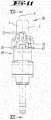
- a preferred embodiment of a fluid injection assembly 36 in accordance to the invention for an internal combustion engine is depicted by Figures 10-12 and (without the injection tube) by Fig. 1 . It extends along a central longitudinal axis L and comprises an injector 37, the above-described injector cup 1 and the above-described spring clip 20.
- the injector itself inter alia includes an injector tube 38, an injector body 39 and a casing 40 for accommodating further parts of the injector 37 like for example a solenoid.
- the injector body 39 is also shown by Fig. 2 . It has a central opening 41 which extends along the longitudinal axis L.
- the injector body 39 has a flat slit 42 which in the example extends parallel to a plane which is orthogonally to the longitudinal axis L so that the slit 42 crosses the central opening 41.
- the injector tube 38 In the mounted state (see for example Fig. 12 ) the injector tube 38 extends through the central opening 41 along the longitudinal axis L.
- the flat sections 26 of the legs 21 of the spring clip 20 are inserted into the slit 42 so that the flat sections 26 encompass the injector tube 38 and are pressed against the injector tube 38 due to elastic bending forces.
- the fork arms 22 extend along the longitudinal axis L in a direction toward a fluid inlet end 43 of the injector 37.
- Said fluid inlet end 43 of the injector 37 is sealingly pressed into a cavity 44 of the injector cup 1.
- the tips 35 of the projections 31 are arranged in a lateral tip distance T from each other as shown by Fig. 5 , for example. Between the wings 12 is a clearance 45 which has a width 49 which is less compared to the lateral tip distance T.
- the fork arms 22 extend through the clearance 45 wherein each of the projections 31 is in contact to respective one of the wings 12.
- the respective first surface 33 is in contact to a respective edge 19 (see Fig. 9 ).
- Each of the curved sections 24 of the spring clip 20 comprises a respective free end section 46, wherein both free end sections 46 are elastically pressed against the base surface 7 of the cup ring element 3 because of a slight elastic compression of the curved sections 24 in a direction parallel to the longitudinal axis L.
- the injection body 39 is made of plastic material and is fabricated by overmolding onto the injector tube 38.
- the injector body 39 comprises a radially extending protrusion 47 having a width W along a direction which is orthogonal to the radial direction. Between the clip reference plane 28 and the connecting portion 23 the angled sections 25 have a lateral clearance 48 between them which has a lateral width C which is slightly bigger compared to the protrusion width W.
- the protrusion 47 extends radially into the lateral clearance 48 between the fork arms 22 so that the protrusion 47 and the fork arms 22 act together for blocking a rotation relative to each other around the central longitudinal axis L.
- the first surface 33 and the second surface 34 are both even.
- the second embodiment of the spring clip as shown by Fig. 6 the first surface 33 has a concave curvature in a cross section which is orthogonal to the edge 19.
Landscapes
- Engineering & Computer Science (AREA)
- Chemical & Material Sciences (AREA)
- Combustion & Propulsion (AREA)
- Mechanical Engineering (AREA)
- General Engineering & Computer Science (AREA)
- Manufacturing & Machinery (AREA)
- Fuel-Injection Apparatus (AREA)
Priority Applications (5)
| Application Number | Priority Date | Filing Date | Title |
|---|---|---|---|
| EP16193477.3A EP3309385B1 (de) | 2016-10-12 | 2016-10-12 | Injektorbecher, federklammer, flüssigkeitsinjektionsanordnung und verfahren zur anordnung davon |
| US16/340,125 US11242833B2 (en) | 2016-10-12 | 2017-10-10 | Injector cup, spring clip, and fluid injection assembly |
| KR1020197013251A KR20190060833A (ko) | 2016-10-12 | 2017-10-10 | 분사기 컵, 스프링 클립, 유체 분사 조립체, 및 이의 조립 방법 |
| CN201780063443.7A CN109863297B (zh) | 2016-10-12 | 2017-10-10 | 喷射器杯、弹簧夹、流体喷射组件和用于其组装的方法 |
| PCT/EP2017/075836 WO2018069336A1 (en) | 2016-10-12 | 2017-10-10 | Injector cup, spring clip, fluid injection assembly and method for its assembling |
Applications Claiming Priority (1)
| Application Number | Priority Date | Filing Date | Title |
|---|---|---|---|
| EP16193477.3A EP3309385B1 (de) | 2016-10-12 | 2016-10-12 | Injektorbecher, federklammer, flüssigkeitsinjektionsanordnung und verfahren zur anordnung davon |
Publications (2)
| Publication Number | Publication Date |
|---|---|
| EP3309385A1 true EP3309385A1 (de) | 2018-04-18 |
| EP3309385B1 EP3309385B1 (de) | 2024-12-11 |
Family
ID=57206014
Family Applications (1)
| Application Number | Title | Priority Date | Filing Date |
|---|---|---|---|
| EP16193477.3A Active EP3309385B1 (de) | 2016-10-12 | 2016-10-12 | Injektorbecher, federklammer, flüssigkeitsinjektionsanordnung und verfahren zur anordnung davon |
Country Status (5)
| Country | Link |
|---|---|
| US (1) | US11242833B2 (de) |
| EP (1) | EP3309385B1 (de) |
| KR (1) | KR20190060833A (de) |
| CN (1) | CN109863297B (de) |
| WO (1) | WO2018069336A1 (de) |
Families Citing this family (5)
| Publication number | Priority date | Publication date | Assignee | Title |
|---|---|---|---|---|
| EP3309385B1 (de) | 2016-10-12 | 2024-12-11 | Vitesco Technologies GmbH | Injektorbecher, federklammer, flüssigkeitsinjektionsanordnung und verfahren zur anordnung davon |
| US11674488B2 (en) | 2019-05-29 | 2023-06-13 | Robert Bosch Gmbh | Fluid injector mounting cup |
| DE102020202949A1 (de) * | 2020-03-09 | 2021-09-09 | Robert Bosch Gesellschaft mit beschränkter Haftung | Brennstoffeinspritzvorrichtung |
| KR102400480B1 (ko) * | 2020-10-06 | 2022-05-20 | 주식회사 현대케피코 | 인젝터 회전방지 클립 |
| WO2023068223A1 (ja) * | 2021-10-19 | 2023-04-27 | 日立Astemo株式会社 | 燃料噴射弁の支持構造 |
Citations (4)
| Publication number | Priority date | Publication date | Assignee | Title |
|---|---|---|---|---|
| EP2221469A1 (de) * | 2009-02-18 | 2010-08-25 | Continental Automotive GmbH | Befestigungselement und Fluidinjektoranordnung |
| EP2388469A1 (de) * | 2010-05-18 | 2011-11-23 | Continental Automotive GmbH | Tankdeckel |
| EP2860388A1 (de) | 2013-10-10 | 2015-04-15 | Continental Automotive GmbH | Brennstoffeinspritzvorrichtung für einen Verbrennungsmotor |
| EP2910768A1 (de) | 2014-02-25 | 2015-08-26 | Continental Automotive GmbH | Kraftstoffleistenvorrichtung für einen Verbrennungsmotor und Verfahren zu ihrer Herstellung |
Family Cites Families (17)
| Publication number | Priority date | Publication date | Assignee | Title |
|---|---|---|---|---|
| US5501195A (en) * | 1994-09-16 | 1996-03-26 | Siemens Automotive Corporation | Retainer arrangement for a bottom feed fuel injector |
| US5970953A (en) * | 1999-01-12 | 1999-10-26 | Siemens Automotive Corporation | High pressure injector clip |
| US6276339B1 (en) * | 2000-05-02 | 2001-08-21 | Delphi Technologies, Inc. | Fuel injector spring clip assembly |
| US6481420B2 (en) * | 2001-01-30 | 2002-11-19 | Visteon Global Technologies, Inc. | Method and apparatus for maintaining the alignment of a fuel injector |
| DE20104270U1 (de) * | 2001-03-13 | 2002-07-18 | Robert Bosch Gmbh, 70469 Stuttgart | Verbindung zweier koaxial hintereinander angeordneter Elemente einer Kraftstoffversorgungsanlage einer Brennkraftmaschine |
| DE10359299A1 (de) * | 2003-12-17 | 2005-08-25 | Robert Bosch Gmbh | Stützelement |
| DE102004048401A1 (de) * | 2004-10-01 | 2006-04-06 | Robert Bosch Gmbh | Niederhalter für eine Brennstoffeinspritzvorrichtung und Brennstoffeinspritzvorrichtung |
| US7360524B2 (en) * | 2004-12-03 | 2008-04-22 | Millenium Industries, Inc. | Fuel injector retention clip |
| EP1703121A1 (de) | 2005-02-24 | 2006-09-20 | Siemens VDO Automotive S.p.A. | Klammer und Kraftstoffeinspritzvorrichtung |
| US8997717B2 (en) * | 2010-03-25 | 2015-04-07 | Denso International America, Inc. | Integrated fuel injector orientation and retention device |
| US9115679B2 (en) * | 2012-02-01 | 2015-08-25 | Denso International America, Inc. | Mounting point injector clip |
| JP5822271B2 (ja) * | 2012-02-27 | 2015-11-24 | 株式会社ケーヒン | 燃料噴射弁の支持構造 |
| WO2013167447A1 (en) * | 2012-05-08 | 2013-11-14 | Continental Automotive Gmbh | Coupling device and fuel injector assembly |
| EP2824312B1 (de) * | 2013-07-10 | 2017-06-28 | Continental Automotive GmbH | Brennstoffeinspritzvorrichtung für einen Verbrennungsmotor |
| KR101739694B1 (ko) * | 2016-06-13 | 2017-05-24 | 주식회사 현대케피코 | 인젝터 클립 |
| EP3279463A1 (de) * | 2016-08-04 | 2018-02-07 | Continental Automotive GmbH | Kraftstoffeinspritzanordnung für einen verbrennungsmotor |
| EP3309385B1 (de) | 2016-10-12 | 2024-12-11 | Vitesco Technologies GmbH | Injektorbecher, federklammer, flüssigkeitsinjektionsanordnung und verfahren zur anordnung davon |
-
2016
- 2016-10-12 EP EP16193477.3A patent/EP3309385B1/de active Active
-
2017
- 2017-10-10 KR KR1020197013251A patent/KR20190060833A/ko not_active Ceased
- 2017-10-10 WO PCT/EP2017/075836 patent/WO2018069336A1/en not_active Ceased
- 2017-10-10 US US16/340,125 patent/US11242833B2/en active Active
- 2017-10-10 CN CN201780063443.7A patent/CN109863297B/zh active Active
Patent Citations (4)
| Publication number | Priority date | Publication date | Assignee | Title |
|---|---|---|---|---|
| EP2221469A1 (de) * | 2009-02-18 | 2010-08-25 | Continental Automotive GmbH | Befestigungselement und Fluidinjektoranordnung |
| EP2388469A1 (de) * | 2010-05-18 | 2011-11-23 | Continental Automotive GmbH | Tankdeckel |
| EP2860388A1 (de) | 2013-10-10 | 2015-04-15 | Continental Automotive GmbH | Brennstoffeinspritzvorrichtung für einen Verbrennungsmotor |
| EP2910768A1 (de) | 2014-02-25 | 2015-08-26 | Continental Automotive GmbH | Kraftstoffleistenvorrichtung für einen Verbrennungsmotor und Verfahren zu ihrer Herstellung |
Also Published As
| Publication number | Publication date |
|---|---|
| US11242833B2 (en) | 2022-02-08 |
| CN109863297A (zh) | 2019-06-07 |
| CN109863297B (zh) | 2021-09-24 |
| WO2018069336A1 (en) | 2018-04-19 |
| US20200011280A1 (en) | 2020-01-09 |
| EP3309385B1 (de) | 2024-12-11 |
| KR20190060833A (ko) | 2019-06-03 |
Similar Documents
| Publication | Publication Date | Title |
|---|---|---|
| EP3309385B1 (de) | Injektorbecher, federklammer, flüssigkeitsinjektionsanordnung und verfahren zur anordnung davon | |
| US9938948B2 (en) | Fluid injection assembly for a combustion engine | |
| US10047711B2 (en) | Fuel injection assembly for a combustion engine | |
| KR101562838B1 (ko) | 연료 분사 장치용 홀드-다운 부재 | |
| US9518544B2 (en) | Fuel rail with pressure pulsation damper | |
| EP2941559B1 (de) | Kraftstoffeinspritzanordnung | |
| CN105593512A (zh) | 燃料喷射装置用喷嘴板的安装构造 | |
| US20160237968A1 (en) | Attachment structure of fuel injection device nozzle plate | |
| US11204008B2 (en) | Fuel injection assembly for an internal combustion engine | |
| CN105658949A (zh) | 用于燃烧发动机的流体喷射组件 | |
| US20110011361A1 (en) | Coupling device | |
| US10190557B2 (en) | Fuel injector mounting device and fuel rail | |
| KR101963955B1 (ko) | 내연기관용 연료 전달 조립체 | |
| EP3361127A1 (de) | Einsteckverbindung zwischen einem anschlussteil und einem einsteckteil | |
| JP6565344B2 (ja) | 内燃機関用のスパークプラグ及びその製造方法 | |
| EP3786441A1 (de) | Kraftstoffeinspritzanordnung für eine brennkraftmaschine | |
| EP1793122B1 (de) | Kraftstoffeinspritzvorrichtung | |
| US20180135582A1 (en) | Injector cup assembly | |
| EP3786440A1 (de) | Kraftstoffeinspritzanordnung für eine brennkraftmaschine und haltekomponente | |
| US20200032754A1 (en) | Assembly for a combustion engine |
Legal Events
| Date | Code | Title | Description |
|---|---|---|---|
| PUAI | Public reference made under article 153(3) epc to a published international application that has entered the european phase |
Free format text: ORIGINAL CODE: 0009012 |
|
| STAA | Information on the status of an ep patent application or granted ep patent |
Free format text: STATUS: THE APPLICATION HAS BEEN PUBLISHED |
|
| AK | Designated contracting states |
Kind code of ref document: A1 Designated state(s): AL AT BE BG CH CY CZ DE DK EE ES FI FR GB GR HR HU IE IS IT LI LT LU LV MC MK MT NL NO PL PT RO RS SE SI SK SM TR |
|
| AX | Request for extension of the european patent |
Extension state: BA ME |
|
| STAA | Information on the status of an ep patent application or granted ep patent |
Free format text: STATUS: REQUEST FOR EXAMINATION WAS MADE |
|
| 17P | Request for examination filed |
Effective date: 20181018 |
|
| RBV | Designated contracting states (corrected) |
Designated state(s): AL AT BE BG CH CY CZ DE DK EE ES FI FR GB GR HR HU IE IS IT LI LT LU LV MC MK MT NL NO PL PT RO RS SE SI SK SM TR |
|
| STAA | Information on the status of an ep patent application or granted ep patent |
Free format text: STATUS: EXAMINATION IS IN PROGRESS |
|
| 17Q | First examination report despatched |
Effective date: 20191219 |
|
| RAP1 | Party data changed (applicant data changed or rights of an application transferred) |
Owner name: VITESCO TECHNOLOGIES GMBH |
|
| RAP3 | Party data changed (applicant data changed or rights of an application transferred) |
Owner name: VITESCO TECHNOLOGIES GMBH |
|
| P01 | Opt-out of the competence of the unified patent court (upc) registered |
Effective date: 20230530 |
|
| GRAP | Despatch of communication of intention to grant a patent |
Free format text: ORIGINAL CODE: EPIDOSNIGR1 |
|
| STAA | Information on the status of an ep patent application or granted ep patent |
Free format text: STATUS: GRANT OF PATENT IS INTENDED |
|
| INTG | Intention to grant announced |
Effective date: 20240705 |
|
| GRAS | Grant fee paid |
Free format text: ORIGINAL CODE: EPIDOSNIGR3 |
|
| GRAA | (expected) grant |
Free format text: ORIGINAL CODE: 0009210 |
|
| STAA | Information on the status of an ep patent application or granted ep patent |
Free format text: STATUS: THE PATENT HAS BEEN GRANTED |
|
| AK | Designated contracting states |
Kind code of ref document: B1 Designated state(s): AL AT BE BG CH CY CZ DE DK EE ES FI FR GB GR HR HU IE IS IT LI LT LU LV MC MK MT NL NO PL PT RO RS SE SI SK SM TR |
|
| REG | Reference to a national code |
Ref country code: GB Ref legal event code: FG4D |
|
| REG | Reference to a national code |
Ref country code: CH Ref legal event code: EP |
|
| REG | Reference to a national code |
Ref country code: IE Ref legal event code: FG4D |
|
| REG | Reference to a national code |
Ref country code: DE Ref legal event code: R096 Ref document number: 602016090575 Country of ref document: DE |
|
| RAP2 | Party data changed (patent owner data changed or rights of a patent transferred) |
Owner name: SCHAEFFLER TECHNOLOGIES AG & CO. KG |
|
| REG | Reference to a national code |
Ref country code: LT Ref legal event code: MG9D |
|
| PG25 | Lapsed in a contracting state [announced via postgrant information from national office to epo] |
Ref country code: HR Free format text: LAPSE BECAUSE OF FAILURE TO SUBMIT A TRANSLATION OF THE DESCRIPTION OR TO PAY THE FEE WITHIN THE PRESCRIBED TIME-LIMIT Effective date: 20241211 |
|
| PG25 | Lapsed in a contracting state [announced via postgrant information from national office to epo] |
Ref country code: FI Free format text: LAPSE BECAUSE OF FAILURE TO SUBMIT A TRANSLATION OF THE DESCRIPTION OR TO PAY THE FEE WITHIN THE PRESCRIBED TIME-LIMIT Effective date: 20241211 |
|
| PG25 | Lapsed in a contracting state [announced via postgrant information from national office to epo] |
Ref country code: BG Free format text: LAPSE BECAUSE OF FAILURE TO SUBMIT A TRANSLATION OF THE DESCRIPTION OR TO PAY THE FEE WITHIN THE PRESCRIBED TIME-LIMIT Effective date: 20241211 |
|
| REG | Reference to a national code |
Ref country code: NL Ref legal event code: MP Effective date: 20241211 |
|
| PG25 | Lapsed in a contracting state [announced via postgrant information from national office to epo] |
Ref country code: ES Free format text: LAPSE BECAUSE OF FAILURE TO SUBMIT A TRANSLATION OF THE DESCRIPTION OR TO PAY THE FEE WITHIN THE PRESCRIBED TIME-LIMIT Effective date: 20241211 |
|
| PG25 | Lapsed in a contracting state [announced via postgrant information from national office to epo] |
Ref country code: NO Free format text: LAPSE BECAUSE OF FAILURE TO SUBMIT A TRANSLATION OF THE DESCRIPTION OR TO PAY THE FEE WITHIN THE PRESCRIBED TIME-LIMIT Effective date: 20250311 |
|
| PG25 | Lapsed in a contracting state [announced via postgrant information from national office to epo] |
Ref country code: LV Free format text: LAPSE BECAUSE OF FAILURE TO SUBMIT A TRANSLATION OF THE DESCRIPTION OR TO PAY THE FEE WITHIN THE PRESCRIBED TIME-LIMIT Effective date: 20241211 Ref country code: GR Free format text: LAPSE BECAUSE OF FAILURE TO SUBMIT A TRANSLATION OF THE DESCRIPTION OR TO PAY THE FEE WITHIN THE PRESCRIBED TIME-LIMIT Effective date: 20250312 |
|
| PG25 | Lapsed in a contracting state [announced via postgrant information from national office to epo] |
Ref country code: RS Free format text: LAPSE BECAUSE OF FAILURE TO SUBMIT A TRANSLATION OF THE DESCRIPTION OR TO PAY THE FEE WITHIN THE PRESCRIBED TIME-LIMIT Effective date: 20250311 |
|
| PG25 | Lapsed in a contracting state [announced via postgrant information from national office to epo] |
Ref country code: NL Free format text: LAPSE BECAUSE OF FAILURE TO SUBMIT A TRANSLATION OF THE DESCRIPTION OR TO PAY THE FEE WITHIN THE PRESCRIBED TIME-LIMIT Effective date: 20241211 |
|
| REG | Reference to a national code |
Ref country code: AT Ref legal event code: MK05 Ref document number: 1750550 Country of ref document: AT Kind code of ref document: T Effective date: 20241211 |
|
| PG25 | Lapsed in a contracting state [announced via postgrant information from national office to epo] |
Ref country code: SM Free format text: LAPSE BECAUSE OF FAILURE TO SUBMIT A TRANSLATION OF THE DESCRIPTION OR TO PAY THE FEE WITHIN THE PRESCRIBED TIME-LIMIT Effective date: 20241211 |
|
| PG25 | Lapsed in a contracting state [announced via postgrant information from national office to epo] |
Ref country code: PL Free format text: LAPSE BECAUSE OF FAILURE TO SUBMIT A TRANSLATION OF THE DESCRIPTION OR TO PAY THE FEE WITHIN THE PRESCRIBED TIME-LIMIT Effective date: 20241211 |
|
| PG25 | Lapsed in a contracting state [announced via postgrant information from national office to epo] |
Ref country code: IS Free format text: LAPSE BECAUSE OF FAILURE TO SUBMIT A TRANSLATION OF THE DESCRIPTION OR TO PAY THE FEE WITHIN THE PRESCRIBED TIME-LIMIT Effective date: 20250411 |
|
| PG25 | Lapsed in a contracting state [announced via postgrant information from national office to epo] |
Ref country code: PT Free format text: LAPSE BECAUSE OF FAILURE TO SUBMIT A TRANSLATION OF THE DESCRIPTION OR TO PAY THE FEE WITHIN THE PRESCRIBED TIME-LIMIT Effective date: 20250411 |
|
| PG25 | Lapsed in a contracting state [announced via postgrant information from national office to epo] |
Ref country code: EE Free format text: LAPSE BECAUSE OF FAILURE TO SUBMIT A TRANSLATION OF THE DESCRIPTION OR TO PAY THE FEE WITHIN THE PRESCRIBED TIME-LIMIT Effective date: 20241211 |
|
| PG25 | Lapsed in a contracting state [announced via postgrant information from national office to epo] |
Ref country code: RO Free format text: LAPSE BECAUSE OF FAILURE TO SUBMIT A TRANSLATION OF THE DESCRIPTION OR TO PAY THE FEE WITHIN THE PRESCRIBED TIME-LIMIT Effective date: 20241211 Ref country code: AT Free format text: LAPSE BECAUSE OF FAILURE TO SUBMIT A TRANSLATION OF THE DESCRIPTION OR TO PAY THE FEE WITHIN THE PRESCRIBED TIME-LIMIT Effective date: 20241211 |
|
| PG25 | Lapsed in a contracting state [announced via postgrant information from national office to epo] |
Ref country code: SK Free format text: LAPSE BECAUSE OF FAILURE TO SUBMIT A TRANSLATION OF THE DESCRIPTION OR TO PAY THE FEE WITHIN THE PRESCRIBED TIME-LIMIT Effective date: 20241211 |
|
| PG25 | Lapsed in a contracting state [announced via postgrant information from national office to epo] |
Ref country code: CZ Free format text: LAPSE BECAUSE OF FAILURE TO SUBMIT A TRANSLATION OF THE DESCRIPTION OR TO PAY THE FEE WITHIN THE PRESCRIBED TIME-LIMIT Effective date: 20241211 |
|
| PG25 | Lapsed in a contracting state [announced via postgrant information from national office to epo] |
Ref country code: SE Free format text: LAPSE BECAUSE OF FAILURE TO SUBMIT A TRANSLATION OF THE DESCRIPTION OR TO PAY THE FEE WITHIN THE PRESCRIBED TIME-LIMIT Effective date: 20241211 |
|
| REG | Reference to a national code |
Ref country code: DE Ref legal event code: R097 Ref document number: 602016090575 Country of ref document: DE |
|
| PG25 | Lapsed in a contracting state [announced via postgrant information from national office to epo] |
Ref country code: DK Free format text: LAPSE BECAUSE OF FAILURE TO SUBMIT A TRANSLATION OF THE DESCRIPTION OR TO PAY THE FEE WITHIN THE PRESCRIBED TIME-LIMIT Effective date: 20241211 |
|
| PLBE | No opposition filed within time limit |
Free format text: ORIGINAL CODE: 0009261 |
|
| STAA | Information on the status of an ep patent application or granted ep patent |
Free format text: STATUS: NO OPPOSITION FILED WITHIN TIME LIMIT |
|
| 26N | No opposition filed |
Effective date: 20250912 |
|
| PGFP | Annual fee paid to national office [announced via postgrant information from national office to epo] |
Ref country code: DE Payment date: 20251031 Year of fee payment: 10 |
|
| PGFP | Annual fee paid to national office [announced via postgrant information from national office to epo] |
Ref country code: GB Payment date: 20251024 Year of fee payment: 10 |
|
| PGFP | Annual fee paid to national office [announced via postgrant information from national office to epo] |
Ref country code: IT Payment date: 20251024 Year of fee payment: 10 |
|
| PGFP | Annual fee paid to national office [announced via postgrant information from national office to epo] |
Ref country code: FR Payment date: 20251030 Year of fee payment: 10 |