EP3309385B1 - Injektorbecher, federklammer, flüssigkeitsinjektionsanordnung und verfahren zur anordnung davon - Google Patents
Injektorbecher, federklammer, flüssigkeitsinjektionsanordnung und verfahren zur anordnung davon Download PDFInfo
- Publication number
- EP3309385B1 EP3309385B1 EP16193477.3A EP16193477A EP3309385B1 EP 3309385 B1 EP3309385 B1 EP 3309385B1 EP 16193477 A EP16193477 A EP 16193477A EP 3309385 B1 EP3309385 B1 EP 3309385B1
- Authority
- EP
- European Patent Office
- Prior art keywords
- injector
- cup
- reference plane
- wings
- extends
- Prior art date
- Legal status (The legal status is an assumption and is not a legal conclusion. Google has not performed a legal analysis and makes no representation as to the accuracy of the status listed.)
- Active
Links
Images




Classifications
-
- F—MECHANICAL ENGINEERING; LIGHTING; HEATING; WEAPONS; BLASTING
- F02—COMBUSTION ENGINES; HOT-GAS OR COMBUSTION-PRODUCT ENGINE PLANTS
- F02M—SUPPLYING COMBUSTION ENGINES IN GENERAL WITH COMBUSTIBLE MIXTURES OR CONSTITUENTS THEREOF
- F02M61/00—Fuel-injectors not provided for in groups F02M39/00 - F02M57/00 or F02M67/00
- F02M61/14—Arrangements of injectors with respect to engines; Mounting of injectors
-
- F—MECHANICAL ENGINEERING; LIGHTING; HEATING; WEAPONS; BLASTING
- F02—COMBUSTION ENGINES; HOT-GAS OR COMBUSTION-PRODUCT ENGINE PLANTS
- F02M—SUPPLYING COMBUSTION ENGINES IN GENERAL WITH COMBUSTIBLE MIXTURES OR CONSTITUENTS THEREOF
- F02M61/00—Fuel-injectors not provided for in groups F02M39/00 - F02M57/00 or F02M67/00
- F02M61/16—Details not provided for in, or of interest apart from, the apparatus of groups F02M61/02 - F02M61/14
- F02M61/168—Assembling; Disassembling; Manufacturing; Adjusting
-
- F—MECHANICAL ENGINEERING; LIGHTING; HEATING; WEAPONS; BLASTING
- F02—COMBUSTION ENGINES; HOT-GAS OR COMBUSTION-PRODUCT ENGINE PLANTS
- F02M—SUPPLYING COMBUSTION ENGINES IN GENERAL WITH COMBUSTIBLE MIXTURES OR CONSTITUENTS THEREOF
- F02M2200/00—Details of fuel-injection apparatus, not otherwise provided for
- F02M2200/16—Sealing of fuel injection apparatus not otherwise provided for
-
- F—MECHANICAL ENGINEERING; LIGHTING; HEATING; WEAPONS; BLASTING
- F02—COMBUSTION ENGINES; HOT-GAS OR COMBUSTION-PRODUCT ENGINE PLANTS
- F02M—SUPPLYING COMBUSTION ENGINES IN GENERAL WITH COMBUSTIBLE MIXTURES OR CONSTITUENTS THEREOF
- F02M2200/00—Details of fuel-injection apparatus, not otherwise provided for
- F02M2200/80—Fuel injection apparatus manufacture, repair or assembly
- F02M2200/8023—Fuel injection apparatus manufacture, repair or assembly the assembly involving use of quick-acting mechanisms, e.g. clips
-
- F—MECHANICAL ENGINEERING; LIGHTING; HEATING; WEAPONS; BLASTING
- F02—COMBUSTION ENGINES; HOT-GAS OR COMBUSTION-PRODUCT ENGINE PLANTS
- F02M—SUPPLYING COMBUSTION ENGINES IN GENERAL WITH COMBUSTIBLE MIXTURES OR CONSTITUENTS THEREOF
- F02M2200/00—Details of fuel-injection apparatus, not otherwise provided for
- F02M2200/85—Mounting of fuel injection apparatus
- F02M2200/853—Mounting of fuel injection apparatus involving use of quick-acting mechanism, e.g. clips
-
- F—MECHANICAL ENGINEERING; LIGHTING; HEATING; WEAPONS; BLASTING
- F02—COMBUSTION ENGINES; HOT-GAS OR COMBUSTION-PRODUCT ENGINE PLANTS
- F02M—SUPPLYING COMBUSTION ENGINES IN GENERAL WITH COMBUSTIBLE MIXTURES OR CONSTITUENTS THEREOF
- F02M2200/00—Details of fuel-injection apparatus, not otherwise provided for
- F02M2200/85—Mounting of fuel injection apparatus
- F02M2200/856—Mounting of fuel injection apparatus characterised by mounting injector to fuel or common rail, or vice versa
Definitions
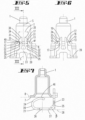
- the injector cup 1' is fixed to a fuel rail 9' by intermediate means 10' .
- a so-called stiffener 11' which is a bended sheetmetal part, is brazed to the injector cup 1' with the double aim of minimizing an injector spring clip inclination and an injector spring clip axial movement, thanks to the locally increased thickness given by the contribute of the two brazed sheet-metal components, i.e. the injector cup in the stiffener.
- a spring clip (which is not shown in Fig. 13 ) can be connected to the injector (also not shown in Fig. 13 ). So the problem of the movement of the injector would imply a risk of loosening the injector during transportation and mounting problems could arise during the assembly in the engine head.
- the injector body has a central opening and a slit, wherein the central opening extends along the longitudinal axis, that the slit crosses the central opening and extends parallel or inclined with respect to a plane which is orthogonally to the longitudinal axis, that the injector tube extends through the central opening, that the flat sections of the legs are inserted in the slit so that the flat sections encompass the injector tube and that the fork arms extend along the longitudinal axis in a direction toward a fluid inlet end of the injector.
- the wings of the injector which may be formed by double bending, also a tilting of the injector with respect to a central longitudinal axis, which can cause disassembling during handling and transport, is limited, in particular thanks to tracks formed by the two bended wings as described before.
- the shape of the wings, in particular their length and width, and/or the shape of the arms, in particular their lengths and shapes of their projections, may be designed and determined in order to guarantee that projections of the arms are in contact with the injector cup also in case of an injector inclination, avoiding as an advantage the risk of a loosening of the injector from the injector cup, for example during transport or handling.
- the injection body consists of or includes plastic material and/or is integrally formed (i.e. formed as a single piece).
- the injection body has been produced by overmolding to the injector tube.
- the injector body comprises a radially extending protrusion having a protrusion width with respect to a circumferential direction, that adjacent to the connecting portion the angle sections 25 have a lateral clearance between them which has a lateral width which is slightly bigger or equal compared to the protrusion width and that the protrusion extends into the lateral clearance between the fork arms so that the protrusion and the fork arms provide a form fit for blocking a rotation relative to each other around the central longitudinal axis.
- the protrusion and the lateral clearance act together for an indexing (anti-rotation) function whereby the protrusion provides a rotational stop with respect to the arms of the spring clip.
- the injector cup is an injector cup according to one or more of claims 1 - 5
- the spring clip is a spring clip according to one or more of claims 6 - 9
- the flat sections of the legs are inserted into the slit so that the flat sections encompass the injector tube and in particular so that the protrusion extends into the lateral clearance between the angled sections of the legs, and subsequently a fluid inlet end of the injector is axially inserted into a cavity of the injector cup by passing the fork arms of the spring clip through the clearance between the wings so that the fork arms starting from an undeformed shape at first are deflected towards each other until the protrusions extend beyond the wings so that the fork arms elastically spring back away from each other.
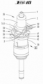
- FIG. 1 and Figs. 4-12 A preferred embodiment of an injector cup 1 in accordance to the invention is shown by Fig. 1 and Figs. 4-12 . It comprises a cup body 2 and a cup ring element 3.
- the cup body 2 extends along a central longitudinal axis A of the injector cup 1 from a first axial end 4 to a second axial end 5.
- the cup ring element 3 adjoins a border 6 of the second axial end 5 by radially extending beyond said border 6.
- a base surface 7 of the cup ring element 3 faces away from the cup body 2 and defines a cup reference plane 8. Said plane extends orthogonally with respect to the longitudinal axis A.
- the cup ring element 3 comprises two wings 12. The wings 12 as well as its respective details are indicated by corresponding reference signs.
- Each wing 12 has a first end section which is integrally connected to the adjoining flat wall 15 of the cup ring element 3. Further, antipodal to the first end each wing 12 has a respective free end section 13 which extends bent away from the cup reference plane 8 at the side of the cup reference plane 8 which is towards the cup body 2. Both wings 12 are spaced from each other by a through opening 14 which extends through the cup ring element 3 in a direction perpendicular to the cup reference plane 8.
- Each end face 16 adjoins its neighboring front side face 17 at an edge 19 which as well as both adjoining faces 16, 17 have a length of some millimeters with respect to a direction which is parallel to the symmetry plane S.
- the injector cup 1 is integrally formed, i.e. formed as a single piece.
- the angled sections 25 extend away from the clip reference plane 28.
- the angled sections 25 are angled by a bending angle ⁇ of 90 degrees with respect to the clip reference plane 28. Both angled sections 25 are laterally connected by the connecting portion 23 (see for example Fig. 5 ) .
- Each fork arm is connected at its respective one end 29 to the connecting portion 23 and extends therefrom towards its respective other end 30 away from the clip reference plane 28.
- Each of the fork arms 22 has at its respective side which faces away respective other fork arm 22 a projection 31 which is directed away from the respective other one of the fork arms 22.
- the spring clip 20 is integrally formed and consists of an elastic metal.
- each of the fork arms 22 comprises a post 32 and the projection 31 which is integrally formed at the respective end 30 of the fork arm 22.
- Each of the projections 31 comprises a first surface 33 and a second surface 34 meeting each other in a tip 35 of the projection 31.
- the tip 35 extends along a line which has a length of some millimeters in the example.
- the injector body 39 has a flat slit 42 which in the example extends parallel to a plane which is orthogonally to the longitudinal axis L so that the slit 42 crosses the central opening 41.
- the injector tube 38 In the mounted state (see for example Fig. 12 ) the injector tube 38 extends through the central opening 41 along the longitudinal axis L.
- the flat sections 26 of the legs 21 of the spring clip 20 are inserted into the slit 42 so that the flat sections 26 encompass the injector tube 38 and are pressed against the injector tube 38 due to elastic bending forces.
- the fork arms 22 extend along the longitudinal axis L in a direction toward a fluid inlet end 43 of the injector 37.
- the injector body 39 comprises a radially extending protrusion 47 having a width W along a direction which is orthogonal to the radial direction. Between the clip reference plane 28 and the connecting portion 23 the angled sections 25 have a lateral clearance 48 between them which has a lateral width C which is slightly bigger compared to the protrusion width W.
- the protrusion 47 extends radially into the lateral clearance 48 between the fork arms 22 so that the protrusion 47 and the fork arms 22 act together for blocking a rotation relative to each other around the central longitudinal axis L.
Landscapes
- Engineering & Computer Science (AREA)
- Chemical & Material Sciences (AREA)
- Combustion & Propulsion (AREA)
- Mechanical Engineering (AREA)
- General Engineering & Computer Science (AREA)
- Manufacturing & Machinery (AREA)
- Fuel-Injection Apparatus (AREA)
Claims (9)
- Injektorbecher (1) für eine Flüssigkeitsinjektionsanordnung für eine interne Brennkraftmaschine, wobei der Injektorbecher (1) Folgendes umfasst:- einen Becherkörper (2), der sich entlang einer mittleren Längsachse (A) des Injektorbechers (1) von einem ersten axialen Ende (4) des Becherkörpers (2) zu einem zweiten axialen Ende (5) des Becherkörpers (2) erstreckt, und- ein Becherringelement (3), das an den Rand (6) des zweiten axialen Endes (5) angrenzt, indem es sich radial über den Rand (6) hinaus erstreckt,wobei eine Basisoberfläche (7) des Becherringelements (3) vom ersten axialen Ende (4) weg zeigt und eine Becherbezugsebene (8) definiert, die sich orthogonal zur Längsachse (A) erstreckt,und wobeidas Becherringelement (3) zwei Flügel (12) umfasst, wobei jeder Flügel (12) einen freien Endabschnitt (13) aufweist, der sich von der Becherbezugsebene (8) weg gebogen an der Seite der Becherbezugsebene (8) erstreckt, die zum Becherkörper (2) zeigt, wobei die zwei Flügel (12) voneinander beabstandet sind und wobei eine Durchgangsöffnung (14) im Becherringelement (3) zwischen den zwei Flügeln (12) bereitgestellt ist, dadurch gekennzeichnet, dass sich eine Schnittlinie oder eine Vertiefung (18), die mit der Durchgangsöffnung (14) eine Form wie ein T-Profil bildet, entlang der Basisoberfläche (7) erstreckt, um die zwei Flügel (12) zu erzeugen, die jeweils eine Endfläche (16) aufweisen, die sich parallel oder geringfügig geneigt zur Becherbezugsebene (8) erstreckt, wobei sich der Endabschnitt (13) jedes Flügels (12) von der Becherbezugsebene (8) wegbiegt.
- Injektorbecher (1) nach dem vorhergehenden Anspruch, wobei jeder Flügel (12) eine Vorderseitenfläche (17) aufweist, die sich um einen Biegewinkel (α) angewinkelt relativ zur Becherbezugsebene (8) erstreckt, wobei beide Vorderseitenflächen (17) zueinander zeigen und/oder wobei beide Flügel (12) spiegelsymmetrisch zueinander gebildet sind und/oder wobei sich die Endabschnitte (13) der Flügel (12) orthogonal bezüglich der Becherbezugsebene (8) erstrecken.
- Injektorbecher (1) nach einem der vorhergehenden Ansprüche, wobei jede Endfläche (16) an ihre benachbarte Vorderseitenfläche (17) an einer Kante (19) angrenzt, wobei die Kante (19) eine Länge im Bereich von einigen Millimetern aufweist und/oder wobei die Endfläche in einer Richtung parallel zu dieser Kante (19) eine Länge im Bereich von einigen Millimetern aufweist.
- Flüssigkeitsinjektionsanordnung (36) für eine interne Brennkraftmaschine, wobei sich die Flüssigkeitsinjektionsanordnung (36) entlang einer mittleren Längsachse (L) erstreckt und Folgendes umfasst:- einen Injektor (37), umfassend ein Injektorrohr (38) und einen Injektorkörper (39), der an dem Injektorrohr (38) befestigt ist,- einen Injektorbecher und- eine Federklammer, die Folgendes umfasst- zwei Schenkel (21), die sich längs erstrecken und voneinander beabstandet sind,- zwei Gabelarme (22), die sich längs erstrecken und voneinander beabstandet sind, und- einen Verbindungsteil (23),
wobei- jeder der Schenkel (21) einen gekrümmten Abschnitt (24), einen angewinkelten Abschnitt (25) und einen flachen Abschnitt (26), der zwischen dem gekrümmten Abschnitt (24) und dem angewinkelten Abschnitt (25) des entsprechenden Schenkels (21) gebildet ist, aufweist,- jeder der flachen Abschnitte (26) eine Basisoberfläche (27) aufweist, die sich entlang einer Klammerbezugsebene (28) erstreckt oder die zumindest tangential zu einer Klammerbezugsebene (28) ist,- an der Seite der Klammerbezugsebene (28), die von den Basisoberflächen (27) wegzeigt, sich jeder der gekrümmten Abschnitte (24) weg von der Klammerbezugsebene (28) erstreckt, indem er eine Form wie ein C-Profil aufweist, und- an der Seite der Klammerbezugsebene (28) die von den Basisoberflächen (27) wegzeigt, sich die angewinkelten Abschnitte (25) weg von der Klammerbezugsebene (28) erstrecken und, insbesondere beabstandet von der Klammerbezugsebene (28), durch den Verbindungsteil (23) miteinander verbunden sind, wobei- jeder der Gabelarme an seinem entsprechenden einen Ende mit dem Verbindungsteil (23) verbunden ist und sich von dem Verbindungsteil (23) hin zu seinem entsprechenden anderen Ende (30) weg von der Klammerbezugsebene (28) erstreckt,- jeder der Gabelarme (22) an seiner entsprechenden Seite, die von dem entsprechenden anderen Gabelarm (22) wegzeigt, einen Vorsprung (31) umfasst, der von dem Verbindungsteil (23) beabstandet ist und der von dem entsprechenden anderen Gabelarm (22) weg gerichtet ist, und- zumindest einer der Gabelarme (22) oder jeder der Gabelarme (20) in Richtung des entsprechenden anderen Gabelarms elastisch durchbiegbar ist.dadurch gekennzeichnet, dass
der Injektorbecher (1) ein Injektorbecher (1) nach einem oder mehreren der Ansprüche 1 - 4 ist und dadurch, dass ein Flüssigkeitseinlassende (43) des Injektors (37) abdichtend in einen Hohlraum (44) des Injektorbechers (1) eingesetzt ist, dadurch, dass jeder Vorsprung eine Spitze umfasst, wobei die Spitzen in einem lateralen Spitzenabstand (T) voneinander angeordnet sind, dadurch, dass zwischen den Flügeln (12) ein Spalt (45) bereitgestellt ist, der eine Breite (49) aufweist, die kleiner im Vergleich mit dem lateralen Spitzenabstand (T) ist, dadurch, dass sich die Gabelarme (22) durch den Spalt (45) zwischen den Flügeln (12) erstrecken, wobei der eine der Vorsprünge (31), insbesondere an seiner ersten Oberfläche, in Kontakt mit dem einen der Flügel (12) ist und der andere der Vorsprünge (31), insbesondere an seiner ersten Oberfläche, in Kontakt mit dem anderen der Flügel (12) ist. - Flüssigkeitsinjektionsanordnung (36) nach dem vorhergehenden Anspruch, wobei- der Injektorkörper (39) eine mittlere Öffnung (41) und einen Schlitz (42) aufweist, wobei sich die mittlere Öffnung entlang der Längsachse (L) erstreckt,- der Schlitz (42) die mittlere Öffnung (41) kreuzt und sich parallel oder geneigt bezüglich einer Ebene, die orthogonal zur Längsachse (L) ist, erstreckt,- sich das Injektorrohr (38) durch die mittlere Öffnung (41) erstreckt,- die flachen Abschnitte (26) der Schenkel (21) in den Schlitz (42) eingesetzt werden, sodass die flachen Abschnitte (26) das Injektorrohr (38) umschließen, und- sich die Gabelarme (22) entlang der Längsachse (L) in einer Richtung hin zu einem Flüssigkeitseinlassende (43) des Injektors (22) erstrecken.
- Flüssigkeitsinjektionsanordnung (36) nach einem der Ansprüche 4 oder 5, wobei jeder der gekrümmten Abschnitte (24) der Federklammer (20) einen entsprechenden freien Endabschnitt (46) umfasst, wobei beide freien Endabschnitte (46) aufgrund einer elastischen Komprimierung der gekrümmten Abschnitte (24) gegen die Basisoberfläche (7) des Becherringelements (3) gehalten oder sogar gedrückt werden.
- Flüssigkeitsinjektionsanordnung (36) nach einem der Ansprüche 4 - 6, wobei der Injektionskörper (39) aus einem Kunststoffmaterial besteht oder ein solches umfasst und insbesondere durch Umspritzen des Injektorrohrs (38) gefertigt wurde.
- Flüssigkeitsinjektionsanordnung (36) nach einem der Ansprüche 4 - 7, wobei der Injektorkörper (39) einen sich radial erstreckenden Vorsprung (47), der eine Vorsprungsbreite (W) aufweist, bezüglich einer umlaufenden Richtung umfasst, sodass angrenzend an den Verbindungsteil (23) die angewinkelten Abschnitte (25) einen lateralen Spalt (48) zwischen sich aufweisen, der eine laterale Breite (C) hat, die geringfügig größer oder gleich im Vergleich mit der Vorsprungsbreite (W) ist, und wobei sich der Vorsprung (47) in den lateralen Spalt (48) zwischen den Gabelarmen (22) erstreckt, sodass der Vorsprung (47) und die Gabelarme (22) eine Formpassung zum Blockieren einer Drehung relativ zueinander um eine mittlere Längsachse (L) bereitstellen.
- Verfahren zum Anordnen einer Flüssigkeitsinjektionsanordnung (36) für eine Brennkraftmaschine, das die folgenden Schritte umfasst:- Bereitstellen einer Federklammer (20) und eines Injektorbechers (1) und- Bereitstellen eines Injektors (37), umfassend ein Injektorrohr (38) und einen Injektorkörper (39), der an dem Injektorrohr (38) befestigt ist, wobei der Injektorkörper (39) eine mittlere Öffnung (41) und einen Schlitz (42) aufweist, wobei sich die mittlere Öffnung (41) entlang einer Längsachse der Flüssigkeitsinjektionsanordnung (36) erstreckt und wobei der Schlitz (42) die mittlere Öffnung (41) kreuzt und sich parallel oder geneigt bezüglich einer Ebene, die orthogonal zu einer mittleren Längsachse (L) ist, erstreckt,dadurch gekennzeichnet, dass:- der Injektorbecher (1) ein Injektorbecher (1) nach einem oder mehreren der Ansprüche 1 - 4 ist,- die Federklammer (20) eine Federklammer (20) nach einem oder mehreren der Ansprüche 5 - 8 ist,- die flachen Abschnitte (26) der Schenkel (21) in den Schlitz (42) eingesetzt sind, sodass die flachen Abschnitte (26) das Injektorrohr (38) umschließen, und insbesondere so, dass sich der Vorsprung (47) in den lateralen Spalt (48) zwischen den angewinkelten Abschnitten (25) der Schenkel (21) erstreckt, und - anschließend, ein Flüssigkeitseinlassende (43) des Injektors (37) axial in einen Hohlraum (44) des Injektorbechers (1) eingesetzt wird, indem die Gabelarme (22) der Federklammer (20) durch den Spalt (45) zwischen den Flügeln (20) geführt werden, sodass die Gabelarme (22) beginnend bei einer zuerst nicht verformten Form aufeinander zu durchgebogen werden, bis sich die Vorsprünge (31) über die Flügel (20) hinaus erstrecken, sodass die Gabelarme (22) voneinander weg elastisch zurückfedern.
Priority Applications (5)
| Application Number | Priority Date | Filing Date | Title |
|---|---|---|---|
| EP16193477.3A EP3309385B1 (de) | 2016-10-12 | 2016-10-12 | Injektorbecher, federklammer, flüssigkeitsinjektionsanordnung und verfahren zur anordnung davon |
| KR1020197013251A KR20190060833A (ko) | 2016-10-12 | 2017-10-10 | 분사기 컵, 스프링 클립, 유체 분사 조립체, 및 이의 조립 방법 |
| US16/340,125 US11242833B2 (en) | 2016-10-12 | 2017-10-10 | Injector cup, spring clip, and fluid injection assembly |
| CN201780063443.7A CN109863297B (zh) | 2016-10-12 | 2017-10-10 | 喷射器杯、弹簧夹、流体喷射组件和用于其组装的方法 |
| PCT/EP2017/075836 WO2018069336A1 (en) | 2016-10-12 | 2017-10-10 | Injector cup, spring clip, fluid injection assembly and method for its assembling |
Applications Claiming Priority (1)
| Application Number | Priority Date | Filing Date | Title |
|---|---|---|---|
| EP16193477.3A EP3309385B1 (de) | 2016-10-12 | 2016-10-12 | Injektorbecher, federklammer, flüssigkeitsinjektionsanordnung und verfahren zur anordnung davon |
Publications (2)
| Publication Number | Publication Date |
|---|---|
| EP3309385A1 EP3309385A1 (de) | 2018-04-18 |
| EP3309385B1 true EP3309385B1 (de) | 2024-12-11 |
Family
ID=57206014
Family Applications (1)
| Application Number | Title | Priority Date | Filing Date |
|---|---|---|---|
| EP16193477.3A Active EP3309385B1 (de) | 2016-10-12 | 2016-10-12 | Injektorbecher, federklammer, flüssigkeitsinjektionsanordnung und verfahren zur anordnung davon |
Country Status (5)
| Country | Link |
|---|---|
| US (1) | US11242833B2 (de) |
| EP (1) | EP3309385B1 (de) |
| KR (1) | KR20190060833A (de) |
| CN (1) | CN109863297B (de) |
| WO (1) | WO2018069336A1 (de) |
Families Citing this family (5)
| Publication number | Priority date | Publication date | Assignee | Title |
|---|---|---|---|---|
| EP3309385B1 (de) | 2016-10-12 | 2024-12-11 | Vitesco Technologies GmbH | Injektorbecher, federklammer, flüssigkeitsinjektionsanordnung und verfahren zur anordnung davon |
| EP3959433A1 (de) | 2019-05-29 | 2022-03-02 | Robert Bosch GmbH | Lagerpfanne für einen fluidinjektor |
| DE102020202949A1 (de) * | 2020-03-09 | 2021-09-09 | Robert Bosch Gesellschaft mit beschränkter Haftung | Brennstoffeinspritzvorrichtung |
| KR102400480B1 (ko) * | 2020-10-06 | 2022-05-20 | 주식회사 현대케피코 | 인젝터 회전방지 클립 |
| WO2023068223A1 (ja) * | 2021-10-19 | 2023-04-27 | 日立Astemo株式会社 | 燃料噴射弁の支持構造 |
Family Cites Families (21)
| Publication number | Priority date | Publication date | Assignee | Title |
|---|---|---|---|---|
| US5501195A (en) * | 1994-09-16 | 1996-03-26 | Siemens Automotive Corporation | Retainer arrangement for a bottom feed fuel injector |
| US5970953A (en) * | 1999-01-12 | 1999-10-26 | Siemens Automotive Corporation | High pressure injector clip |
| US6276339B1 (en) * | 2000-05-02 | 2001-08-21 | Delphi Technologies, Inc. | Fuel injector spring clip assembly |
| US6481420B2 (en) * | 2001-01-30 | 2002-11-19 | Visteon Global Technologies, Inc. | Method and apparatus for maintaining the alignment of a fuel injector |
| DE20104270U1 (de) * | 2001-03-13 | 2002-07-18 | Robert Bosch Gmbh, 70469 Stuttgart | Verbindung zweier koaxial hintereinander angeordneter Elemente einer Kraftstoffversorgungsanlage einer Brennkraftmaschine |
| DE10359299A1 (de) * | 2003-12-17 | 2005-08-25 | Robert Bosch Gmbh | Stützelement |
| DE102004048401A1 (de) * | 2004-10-01 | 2006-04-06 | Robert Bosch Gmbh | Niederhalter für eine Brennstoffeinspritzvorrichtung und Brennstoffeinspritzvorrichtung |
| US7360524B2 (en) * | 2004-12-03 | 2008-04-22 | Millenium Industries, Inc. | Fuel injector retention clip |
| EP1703121A1 (de) | 2005-02-24 | 2006-09-20 | Siemens VDO Automotive S.p.A. | Klammer und Kraftstoffeinspritzvorrichtung |
| EP2221469B1 (de) * | 2009-02-18 | 2011-10-12 | Continental Automotive GmbH | Befestigungselement und Fluidinjektoranordnung |
| US8997717B2 (en) * | 2010-03-25 | 2015-04-07 | Denso International America, Inc. | Integrated fuel injector orientation and retention device |
| EP2388469B1 (de) * | 2010-05-18 | 2013-03-13 | Continental Automotive GmbH | Kraftstoffkappe |
| US9115679B2 (en) * | 2012-02-01 | 2015-08-25 | Denso International America, Inc. | Mounting point injector clip |
| JP5822271B2 (ja) * | 2012-02-27 | 2015-11-24 | 株式会社ケーヒン | 燃料噴射弁の支持構造 |
| KR20150006854A (ko) * | 2012-05-08 | 2015-01-19 | 콘티넨탈 오토모티브 게엠베하 | 커플링 장치 및 연료 분사기 조립체 |
| EP2824312B1 (de) * | 2013-07-10 | 2017-06-28 | Continental Automotive GmbH | Brennstoffeinspritzvorrichtung für einen Verbrennungsmotor |
| EP2860388B1 (de) * | 2013-10-10 | 2017-07-26 | Continental Automotive GmbH | Brennstoffeinspritzvorrichtung für einen Verbrennungsmotor |
| EP2910768A1 (de) | 2014-02-25 | 2015-08-26 | Continental Automotive GmbH | Kraftstoffleistenvorrichtung für einen Verbrennungsmotor und Verfahren zu ihrer Herstellung |
| KR101739694B1 (ko) * | 2016-06-13 | 2017-05-24 | 주식회사 현대케피코 | 인젝터 클립 |
| EP3279463A1 (de) * | 2016-08-04 | 2018-02-07 | Continental Automotive GmbH | Kraftstoffeinspritzanordnung für einen verbrennungsmotor |
| EP3309385B1 (de) | 2016-10-12 | 2024-12-11 | Vitesco Technologies GmbH | Injektorbecher, federklammer, flüssigkeitsinjektionsanordnung und verfahren zur anordnung davon |
-
2016
- 2016-10-12 EP EP16193477.3A patent/EP3309385B1/de active Active
-
2017
- 2017-10-10 KR KR1020197013251A patent/KR20190060833A/ko not_active Ceased
- 2017-10-10 CN CN201780063443.7A patent/CN109863297B/zh active Active
- 2017-10-10 WO PCT/EP2017/075836 patent/WO2018069336A1/en not_active Ceased
- 2017-10-10 US US16/340,125 patent/US11242833B2/en active Active
Also Published As
| Publication number | Publication date |
|---|---|
| WO2018069336A1 (en) | 2018-04-19 |
| EP3309385A1 (de) | 2018-04-18 |
| KR20190060833A (ko) | 2019-06-03 |
| CN109863297B (zh) | 2021-09-24 |
| US20200011280A1 (en) | 2020-01-09 |
| US11242833B2 (en) | 2022-02-08 |
| CN109863297A (zh) | 2019-06-07 |
Similar Documents
| Publication | Publication Date | Title |
|---|---|---|
| US11242833B2 (en) | Injector cup, spring clip, and fluid injection assembly | |
| US9938948B2 (en) | Fluid injection assembly for a combustion engine | |
| CN104279103B (zh) | 用于燃烧发动机的燃料喷射组件 | |
| KR101562838B1 (ko) | 연료 분사 장치용 홀드-다운 부재 | |
| US9518544B2 (en) | Fuel rail with pressure pulsation damper | |
| EP2941559B1 (de) | Kraftstoffeinspritzanordnung | |
| CN108915921B (zh) | 燃料喷射装置用喷嘴板的安装构造 | |
| KR101857373B1 (ko) | 연소 엔진용 유체 분사 조립체 | |
| US20160237968A1 (en) | Attachment structure of fuel injection device nozzle plate | |
| US20110011361A1 (en) | Coupling device | |
| US10190557B2 (en) | Fuel injector mounting device and fuel rail | |
| KR101963955B1 (ko) | 내연기관용 연료 전달 조립체 | |
| US9587607B2 (en) | Alignment element for an injector, and method for manufacturing an injector | |
| EP3508716A1 (de) | Kombination einer klammer und eines ausrichtelements und fluidinjektionsvorrichtung | |
| JP7452269B2 (ja) | 内燃機関用のスパークプラグ | |
| EP3786441A1 (de) | Kraftstoffeinspritzanordnung für eine brennkraftmaschine | |
| US20180135582A1 (en) | Injector cup assembly | |
| EP3786440A1 (de) | Kraftstoffeinspritzanordnung für eine brennkraftmaschine und haltekomponente | |
| US11143410B1 (en) | Holder assembly for a burner of a gas cooking appliance | |
| US20200032754A1 (en) | Assembly for a combustion engine | |
| EP3636915A1 (de) | Kraftstoffeinspritzanordnung für einen verbrennungsmotor | |
| EP1258630A1 (de) | Kraftstoffeinspritzventil-Zusammenbau |
Legal Events
| Date | Code | Title | Description |
|---|---|---|---|
| PUAI | Public reference made under article 153(3) epc to a published international application that has entered the european phase |
Free format text: ORIGINAL CODE: 0009012 |
|
| STAA | Information on the status of an ep patent application or granted ep patent |
Free format text: STATUS: THE APPLICATION HAS BEEN PUBLISHED |
|
| AK | Designated contracting states |
Kind code of ref document: A1 Designated state(s): AL AT BE BG CH CY CZ DE DK EE ES FI FR GB GR HR HU IE IS IT LI LT LU LV MC MK MT NL NO PL PT RO RS SE SI SK SM TR |
|
| AX | Request for extension of the european patent |
Extension state: BA ME |
|
| STAA | Information on the status of an ep patent application or granted ep patent |
Free format text: STATUS: REQUEST FOR EXAMINATION WAS MADE |
|
| 17P | Request for examination filed |
Effective date: 20181018 |
|
| RBV | Designated contracting states (corrected) |
Designated state(s): AL AT BE BG CH CY CZ DE DK EE ES FI FR GB GR HR HU IE IS IT LI LT LU LV MC MK MT NL NO PL PT RO RS SE SI SK SM TR |
|
| STAA | Information on the status of an ep patent application or granted ep patent |
Free format text: STATUS: EXAMINATION IS IN PROGRESS |
|
| 17Q | First examination report despatched |
Effective date: 20191219 |
|
| RAP1 | Party data changed (applicant data changed or rights of an application transferred) |
Owner name: VITESCO TECHNOLOGIES GMBH |
|
| RAP3 | Party data changed (applicant data changed or rights of an application transferred) |
Owner name: VITESCO TECHNOLOGIES GMBH |
|
| P01 | Opt-out of the competence of the unified patent court (upc) registered |
Effective date: 20230530 |
|
| GRAP | Despatch of communication of intention to grant a patent |
Free format text: ORIGINAL CODE: EPIDOSNIGR1 |
|
| STAA | Information on the status of an ep patent application or granted ep patent |
Free format text: STATUS: GRANT OF PATENT IS INTENDED |
|
| INTG | Intention to grant announced |
Effective date: 20240705 |
|
| GRAS | Grant fee paid |
Free format text: ORIGINAL CODE: EPIDOSNIGR3 |
|
| GRAA | (expected) grant |
Free format text: ORIGINAL CODE: 0009210 |
|
| STAA | Information on the status of an ep patent application or granted ep patent |
Free format text: STATUS: THE PATENT HAS BEEN GRANTED |
|
| AK | Designated contracting states |
Kind code of ref document: B1 Designated state(s): AL AT BE BG CH CY CZ DE DK EE ES FI FR GB GR HR HU IE IS IT LI LT LU LV MC MK MT NL NO PL PT RO RS SE SI SK SM TR |
|
| REG | Reference to a national code |
Ref country code: GB Ref legal event code: FG4D |
|
| REG | Reference to a national code |
Ref country code: CH Ref legal event code: EP |
|
| REG | Reference to a national code |
Ref country code: IE Ref legal event code: FG4D |
|
| REG | Reference to a national code |
Ref country code: DE Ref legal event code: R096 Ref document number: 602016090575 Country of ref document: DE |
|
| RAP2 | Party data changed (patent owner data changed or rights of a patent transferred) |
Owner name: SCHAEFFLER TECHNOLOGIES AG & CO. KG |
|
| REG | Reference to a national code |
Ref country code: LT Ref legal event code: MG9D |
|
| PG25 | Lapsed in a contracting state [announced via postgrant information from national office to epo] |
Ref country code: HR Free format text: LAPSE BECAUSE OF FAILURE TO SUBMIT A TRANSLATION OF THE DESCRIPTION OR TO PAY THE FEE WITHIN THE PRESCRIBED TIME-LIMIT Effective date: 20241211 |
|
| PG25 | Lapsed in a contracting state [announced via postgrant information from national office to epo] |
Ref country code: FI Free format text: LAPSE BECAUSE OF FAILURE TO SUBMIT A TRANSLATION OF THE DESCRIPTION OR TO PAY THE FEE WITHIN THE PRESCRIBED TIME-LIMIT Effective date: 20241211 |
|
| PG25 | Lapsed in a contracting state [announced via postgrant information from national office to epo] |
Ref country code: BG Free format text: LAPSE BECAUSE OF FAILURE TO SUBMIT A TRANSLATION OF THE DESCRIPTION OR TO PAY THE FEE WITHIN THE PRESCRIBED TIME-LIMIT Effective date: 20241211 |
|
| REG | Reference to a national code |
Ref country code: NL Ref legal event code: MP Effective date: 20241211 |
|
| PG25 | Lapsed in a contracting state [announced via postgrant information from national office to epo] |
Ref country code: ES Free format text: LAPSE BECAUSE OF FAILURE TO SUBMIT A TRANSLATION OF THE DESCRIPTION OR TO PAY THE FEE WITHIN THE PRESCRIBED TIME-LIMIT Effective date: 20241211 |
|
| PG25 | Lapsed in a contracting state [announced via postgrant information from national office to epo] |
Ref country code: NO Free format text: LAPSE BECAUSE OF FAILURE TO SUBMIT A TRANSLATION OF THE DESCRIPTION OR TO PAY THE FEE WITHIN THE PRESCRIBED TIME-LIMIT Effective date: 20250311 |
|
| PG25 | Lapsed in a contracting state [announced via postgrant information from national office to epo] |
Ref country code: LV Free format text: LAPSE BECAUSE OF FAILURE TO SUBMIT A TRANSLATION OF THE DESCRIPTION OR TO PAY THE FEE WITHIN THE PRESCRIBED TIME-LIMIT Effective date: 20241211 Ref country code: GR Free format text: LAPSE BECAUSE OF FAILURE TO SUBMIT A TRANSLATION OF THE DESCRIPTION OR TO PAY THE FEE WITHIN THE PRESCRIBED TIME-LIMIT Effective date: 20250312 |
|
| PG25 | Lapsed in a contracting state [announced via postgrant information from national office to epo] |
Ref country code: RS Free format text: LAPSE BECAUSE OF FAILURE TO SUBMIT A TRANSLATION OF THE DESCRIPTION OR TO PAY THE FEE WITHIN THE PRESCRIBED TIME-LIMIT Effective date: 20250311 |
|
| PG25 | Lapsed in a contracting state [announced via postgrant information from national office to epo] |
Ref country code: NL Free format text: LAPSE BECAUSE OF FAILURE TO SUBMIT A TRANSLATION OF THE DESCRIPTION OR TO PAY THE FEE WITHIN THE PRESCRIBED TIME-LIMIT Effective date: 20241211 |
|
| REG | Reference to a national code |
Ref country code: AT Ref legal event code: MK05 Ref document number: 1750550 Country of ref document: AT Kind code of ref document: T Effective date: 20241211 |
|
| PG25 | Lapsed in a contracting state [announced via postgrant information from national office to epo] |
Ref country code: SM Free format text: LAPSE BECAUSE OF FAILURE TO SUBMIT A TRANSLATION OF THE DESCRIPTION OR TO PAY THE FEE WITHIN THE PRESCRIBED TIME-LIMIT Effective date: 20241211 |
|
| PG25 | Lapsed in a contracting state [announced via postgrant information from national office to epo] |
Ref country code: PL Free format text: LAPSE BECAUSE OF FAILURE TO SUBMIT A TRANSLATION OF THE DESCRIPTION OR TO PAY THE FEE WITHIN THE PRESCRIBED TIME-LIMIT Effective date: 20241211 |
|
| PG25 | Lapsed in a contracting state [announced via postgrant information from national office to epo] |
Ref country code: IS Free format text: LAPSE BECAUSE OF FAILURE TO SUBMIT A TRANSLATION OF THE DESCRIPTION OR TO PAY THE FEE WITHIN THE PRESCRIBED TIME-LIMIT Effective date: 20250411 |
|
| PG25 | Lapsed in a contracting state [announced via postgrant information from national office to epo] |
Ref country code: PT Free format text: LAPSE BECAUSE OF FAILURE TO SUBMIT A TRANSLATION OF THE DESCRIPTION OR TO PAY THE FEE WITHIN THE PRESCRIBED TIME-LIMIT Effective date: 20250411 |
|
| PG25 | Lapsed in a contracting state [announced via postgrant information from national office to epo] |
Ref country code: EE Free format text: LAPSE BECAUSE OF FAILURE TO SUBMIT A TRANSLATION OF THE DESCRIPTION OR TO PAY THE FEE WITHIN THE PRESCRIBED TIME-LIMIT Effective date: 20241211 |
|
| PG25 | Lapsed in a contracting state [announced via postgrant information from national office to epo] |
Ref country code: RO Free format text: LAPSE BECAUSE OF FAILURE TO SUBMIT A TRANSLATION OF THE DESCRIPTION OR TO PAY THE FEE WITHIN THE PRESCRIBED TIME-LIMIT Effective date: 20241211 Ref country code: AT Free format text: LAPSE BECAUSE OF FAILURE TO SUBMIT A TRANSLATION OF THE DESCRIPTION OR TO PAY THE FEE WITHIN THE PRESCRIBED TIME-LIMIT Effective date: 20241211 |
|
| PG25 | Lapsed in a contracting state [announced via postgrant information from national office to epo] |
Ref country code: SK Free format text: LAPSE BECAUSE OF FAILURE TO SUBMIT A TRANSLATION OF THE DESCRIPTION OR TO PAY THE FEE WITHIN THE PRESCRIBED TIME-LIMIT Effective date: 20241211 |
|
| PG25 | Lapsed in a contracting state [announced via postgrant information from national office to epo] |
Ref country code: CZ Free format text: LAPSE BECAUSE OF FAILURE TO SUBMIT A TRANSLATION OF THE DESCRIPTION OR TO PAY THE FEE WITHIN THE PRESCRIBED TIME-LIMIT Effective date: 20241211 |
|
| PG25 | Lapsed in a contracting state [announced via postgrant information from national office to epo] |
Ref country code: SE Free format text: LAPSE BECAUSE OF FAILURE TO SUBMIT A TRANSLATION OF THE DESCRIPTION OR TO PAY THE FEE WITHIN THE PRESCRIBED TIME-LIMIT Effective date: 20241211 |
|
| REG | Reference to a national code |
Ref country code: DE Ref legal event code: R097 Ref document number: 602016090575 Country of ref document: DE |
|
| PG25 | Lapsed in a contracting state [announced via postgrant information from national office to epo] |
Ref country code: DK Free format text: LAPSE BECAUSE OF FAILURE TO SUBMIT A TRANSLATION OF THE DESCRIPTION OR TO PAY THE FEE WITHIN THE PRESCRIBED TIME-LIMIT Effective date: 20241211 |
|
| PLBE | No opposition filed within time limit |
Free format text: ORIGINAL CODE: 0009261 |
|
| STAA | Information on the status of an ep patent application or granted ep patent |
Free format text: STATUS: NO OPPOSITION FILED WITHIN TIME LIMIT |
|
| 26N | No opposition filed |
Effective date: 20250912 |
|
| PGFP | Annual fee paid to national office [announced via postgrant information from national office to epo] |
Ref country code: DE Payment date: 20251031 Year of fee payment: 10 |
|
| PGFP | Annual fee paid to national office [announced via postgrant information from national office to epo] |
Ref country code: GB Payment date: 20251024 Year of fee payment: 10 |
|
| PGFP | Annual fee paid to national office [announced via postgrant information from national office to epo] |
Ref country code: IT Payment date: 20251024 Year of fee payment: 10 |
|
| PGFP | Annual fee paid to national office [announced via postgrant information from national office to epo] |
Ref country code: FR Payment date: 20251030 Year of fee payment: 10 |