EP3309385B1 - Coupelle d'injecteur, pince à ressort, ensemble d'injection de fluide et son procédé d'assemblage - Google Patents
Coupelle d'injecteur, pince à ressort, ensemble d'injection de fluide et son procédé d'assemblage Download PDFInfo
- Publication number
- EP3309385B1 EP3309385B1 EP16193477.3A EP16193477A EP3309385B1 EP 3309385 B1 EP3309385 B1 EP 3309385B1 EP 16193477 A EP16193477 A EP 16193477A EP 3309385 B1 EP3309385 B1 EP 3309385B1
- Authority
- EP
- European Patent Office
- Prior art keywords
- injector
- cup
- reference plane
- wings
- extends
- Prior art date
- Legal status (The legal status is an assumption and is not a legal conclusion. Google has not performed a legal analysis and makes no representation as to the accuracy of the status listed.)
- Active
Links
Images


Classifications
-
- F—MECHANICAL ENGINEERING; LIGHTING; HEATING; WEAPONS; BLASTING
- F02—COMBUSTION ENGINES; HOT-GAS OR COMBUSTION-PRODUCT ENGINE PLANTS
- F02M—SUPPLYING COMBUSTION ENGINES IN GENERAL WITH COMBUSTIBLE MIXTURES OR CONSTITUENTS THEREOF
- F02M61/00—Fuel-injectors not provided for in groups F02M39/00 - F02M57/00 or F02M67/00
- F02M61/14—Arrangements of injectors with respect to engines; Mounting of injectors
-
- F—MECHANICAL ENGINEERING; LIGHTING; HEATING; WEAPONS; BLASTING
- F02—COMBUSTION ENGINES; HOT-GAS OR COMBUSTION-PRODUCT ENGINE PLANTS
- F02M—SUPPLYING COMBUSTION ENGINES IN GENERAL WITH COMBUSTIBLE MIXTURES OR CONSTITUENTS THEREOF
- F02M61/00—Fuel-injectors not provided for in groups F02M39/00 - F02M57/00 or F02M67/00
- F02M61/16—Details not provided for in, or of interest apart from, the apparatus of groups F02M61/02 - F02M61/14
- F02M61/168—Assembling; Disassembling; Manufacturing; Adjusting
-
- F—MECHANICAL ENGINEERING; LIGHTING; HEATING; WEAPONS; BLASTING
- F02—COMBUSTION ENGINES; HOT-GAS OR COMBUSTION-PRODUCT ENGINE PLANTS
- F02M—SUPPLYING COMBUSTION ENGINES IN GENERAL WITH COMBUSTIBLE MIXTURES OR CONSTITUENTS THEREOF
- F02M2200/00—Details of fuel-injection apparatus, not otherwise provided for
- F02M2200/16—Sealing of fuel injection apparatus not otherwise provided for
-
- F—MECHANICAL ENGINEERING; LIGHTING; HEATING; WEAPONS; BLASTING
- F02—COMBUSTION ENGINES; HOT-GAS OR COMBUSTION-PRODUCT ENGINE PLANTS
- F02M—SUPPLYING COMBUSTION ENGINES IN GENERAL WITH COMBUSTIBLE MIXTURES OR CONSTITUENTS THEREOF
- F02M2200/00—Details of fuel-injection apparatus, not otherwise provided for
- F02M2200/80—Fuel injection apparatus manufacture, repair or assembly
- F02M2200/8023—Fuel injection apparatus manufacture, repair or assembly the assembly involving use of quick-acting mechanisms, e.g. clips
-
- F—MECHANICAL ENGINEERING; LIGHTING; HEATING; WEAPONS; BLASTING
- F02—COMBUSTION ENGINES; HOT-GAS OR COMBUSTION-PRODUCT ENGINE PLANTS
- F02M—SUPPLYING COMBUSTION ENGINES IN GENERAL WITH COMBUSTIBLE MIXTURES OR CONSTITUENTS THEREOF
- F02M2200/00—Details of fuel-injection apparatus, not otherwise provided for
- F02M2200/85—Mounting of fuel injection apparatus
- F02M2200/853—Mounting of fuel injection apparatus involving use of quick-acting mechanism, e.g. clips
-
- F—MECHANICAL ENGINEERING; LIGHTING; HEATING; WEAPONS; BLASTING
- F02—COMBUSTION ENGINES; HOT-GAS OR COMBUSTION-PRODUCT ENGINE PLANTS
- F02M—SUPPLYING COMBUSTION ENGINES IN GENERAL WITH COMBUSTIBLE MIXTURES OR CONSTITUENTS THEREOF
- F02M2200/00—Details of fuel-injection apparatus, not otherwise provided for
- F02M2200/85—Mounting of fuel injection apparatus
- F02M2200/856—Mounting of fuel injection apparatus characterised by mounting injector to fuel or common rail, or vice versa
Definitions
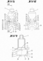
- the injector cup 1' is fixed to a fuel rail 9' by intermediate means 10' .
- a so-called stiffener 11' which is a bended sheetmetal part, is brazed to the injector cup 1' with the double aim of minimizing an injector spring clip inclination and an injector spring clip axial movement, thanks to the locally increased thickness given by the contribute of the two brazed sheet-metal components, i.e. the injector cup in the stiffener.
- a spring clip (which is not shown in Fig. 13 ) can be connected to the injector (also not shown in Fig. 13 ). So the problem of the movement of the injector would imply a risk of loosening the injector during transportation and mounting problems could arise during the assembly in the engine head.
- the injector body has a central opening and a slit, wherein the central opening extends along the longitudinal axis, that the slit crosses the central opening and extends parallel or inclined with respect to a plane which is orthogonally to the longitudinal axis, that the injector tube extends through the central opening, that the flat sections of the legs are inserted in the slit so that the flat sections encompass the injector tube and that the fork arms extend along the longitudinal axis in a direction toward a fluid inlet end of the injector.
- the wings of the injector which may be formed by double bending, also a tilting of the injector with respect to a central longitudinal axis, which can cause disassembling during handling and transport, is limited, in particular thanks to tracks formed by the two bended wings as described before.
- the shape of the wings, in particular their length and width, and/or the shape of the arms, in particular their lengths and shapes of their projections, may be designed and determined in order to guarantee that projections of the arms are in contact with the injector cup also in case of an injector inclination, avoiding as an advantage the risk of a loosening of the injector from the injector cup, for example during transport or handling.
- the injection body consists of or includes plastic material and/or is integrally formed (i.e. formed as a single piece).
- the injection body has been produced by overmolding to the injector tube.
- the injector body comprises a radially extending protrusion having a protrusion width with respect to a circumferential direction, that adjacent to the connecting portion the angle sections 25 have a lateral clearance between them which has a lateral width which is slightly bigger or equal compared to the protrusion width and that the protrusion extends into the lateral clearance between the fork arms so that the protrusion and the fork arms provide a form fit for blocking a rotation relative to each other around the central longitudinal axis.
- the protrusion and the lateral clearance act together for an indexing (anti-rotation) function whereby the protrusion provides a rotational stop with respect to the arms of the spring clip.
- the injector cup is an injector cup according to one or more of claims 1 - 5
- the spring clip is a spring clip according to one or more of claims 6 - 9
- the flat sections of the legs are inserted into the slit so that the flat sections encompass the injector tube and in particular so that the protrusion extends into the lateral clearance between the angled sections of the legs, and subsequently a fluid inlet end of the injector is axially inserted into a cavity of the injector cup by passing the fork arms of the spring clip through the clearance between the wings so that the fork arms starting from an undeformed shape at first are deflected towards each other until the protrusions extend beyond the wings so that the fork arms elastically spring back away from each other.
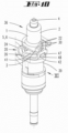
- FIG. 1 and Figs. 4-12 A preferred embodiment of an injector cup 1 in accordance to the invention is shown by Fig. 1 and Figs. 4-12 . It comprises a cup body 2 and a cup ring element 3.
- the cup body 2 extends along a central longitudinal axis A of the injector cup 1 from a first axial end 4 to a second axial end 5.
- the cup ring element 3 adjoins a border 6 of the second axial end 5 by radially extending beyond said border 6.
- a base surface 7 of the cup ring element 3 faces away from the cup body 2 and defines a cup reference plane 8. Said plane extends orthogonally with respect to the longitudinal axis A.
- the cup ring element 3 comprises two wings 12. The wings 12 as well as its respective details are indicated by corresponding reference signs.
- Each wing 12 has a first end section which is integrally connected to the adjoining flat wall 15 of the cup ring element 3. Further, antipodal to the first end each wing 12 has a respective free end section 13 which extends bent away from the cup reference plane 8 at the side of the cup reference plane 8 which is towards the cup body 2. Both wings 12 are spaced from each other by a through opening 14 which extends through the cup ring element 3 in a direction perpendicular to the cup reference plane 8.
- Each end face 16 adjoins its neighboring front side face 17 at an edge 19 which as well as both adjoining faces 16, 17 have a length of some millimeters with respect to a direction which is parallel to the symmetry plane S.
- the injector cup 1 is integrally formed, i.e. formed as a single piece.
- the angled sections 25 extend away from the clip reference plane 28.
- the angled sections 25 are angled by a bending angle ⁇ of 90 degrees with respect to the clip reference plane 28. Both angled sections 25 are laterally connected by the connecting portion 23 (see for example Fig. 5 ) .
- Each fork arm is connected at its respective one end 29 to the connecting portion 23 and extends therefrom towards its respective other end 30 away from the clip reference plane 28.
- Each of the fork arms 22 has at its respective side which faces away respective other fork arm 22 a projection 31 which is directed away from the respective other one of the fork arms 22.
- the spring clip 20 is integrally formed and consists of an elastic metal.
- each of the fork arms 22 comprises a post 32 and the projection 31 which is integrally formed at the respective end 30 of the fork arm 22.
- Each of the projections 31 comprises a first surface 33 and a second surface 34 meeting each other in a tip 35 of the projection 31.
- the tip 35 extends along a line which has a length of some millimeters in the example.
- the injector body 39 has a flat slit 42 which in the example extends parallel to a plane which is orthogonally to the longitudinal axis L so that the slit 42 crosses the central opening 41.
- the injector tube 38 In the mounted state (see for example Fig. 12 ) the injector tube 38 extends through the central opening 41 along the longitudinal axis L.
- the flat sections 26 of the legs 21 of the spring clip 20 are inserted into the slit 42 so that the flat sections 26 encompass the injector tube 38 and are pressed against the injector tube 38 due to elastic bending forces.
- the fork arms 22 extend along the longitudinal axis L in a direction toward a fluid inlet end 43 of the injector 37.
- the injector body 39 comprises a radially extending protrusion 47 having a width W along a direction which is orthogonal to the radial direction. Between the clip reference plane 28 and the connecting portion 23 the angled sections 25 have a lateral clearance 48 between them which has a lateral width C which is slightly bigger compared to the protrusion width W.
- the protrusion 47 extends radially into the lateral clearance 48 between the fork arms 22 so that the protrusion 47 and the fork arms 22 act together for blocking a rotation relative to each other around the central longitudinal axis L.
Landscapes
- Engineering & Computer Science (AREA)
- Chemical & Material Sciences (AREA)
- Combustion & Propulsion (AREA)
- Mechanical Engineering (AREA)
- General Engineering & Computer Science (AREA)
- Manufacturing & Machinery (AREA)
- Fuel-Injection Apparatus (AREA)
Claims (9)
- Coupelle d'injecteur (1) pour un ensemble d'injection de fluide pour un moteur à combustion interne, dans laquelle la coupelle d'injecteur (1) comprend :- un corps de coupelle (2) s'étendant le long d'un axe longitudinal central (A) de la coupelle d'injecteur (1) depuis une première extrémité axiale (4) du corps de coupelle (2) jusqu'à une seconde extrémité axiale (5) du corps de coupelle (2), et- un élément bague de coupelle (3) qui est contigu à la bordure (6) de la seconde extrémité axiale (5) en s'étendant radialement au-delà de ladite bordure (6), dans laquelle une surface de base (7) de l'élément bague de coupelle (3) est tournée dans un sens opposé à la première extrémité axiale (4) et définit un plan de référence de coupelle (8) qui s'étend orthogonalement à l'axe longitudinal (A) ,et dans laquelle
l'élément bague de coupelle (3) comprend deux ailes (12), dans laquelle chaque aile (12) a une section d'extrémité libre (13) qui s'étend pliée dans un sens opposé au plan de référence de coupelle (8) sur le côté du plan de référence de coupelle (8) qui est tourné vers le corps de coupelle (2), dans laquelle les deux ailes (12) sont espacées l'une de l'autre et dans laquelle une ouverture de passage (14) est prévue dans l'élément bague de coupelle (3) entre les deux ailes (12), caractérisée en ce qu'une ligne de découpe ou un évidement (18) présentant une forme comme un profil en T avec l'ouverture de passage (14) s'étend le long de la surface de base (7) afin de créer les deux ailes (12), chacune ayant une face d'extrémité (16) s'étendant parallèlement, ou de façon légèrement inclinée, par rapport au plan de référence de coupelle (8), dans laquelle la section d'extrémité (13) de chaque aile (12) se plie dans un sens opposé au plan de référence de coupelle (8). - Coupelle d'injecteur (1) selon la revendication précédente, dans laquelle chaque aile (12) a une face latérale avant (17) qui s'étend de façon inclinée relativement au plan de référence de coupelle (8) selon un angle de pliage (α) dans laquelle les deux faces latérales avant (17) sont tournées l'une vers l'autre et/ou les deux ailes (12) sont formées en miroir symétriquement l'une à l'autre et/ou les sections d'extrémité (13) des ailes (12) s'étendent orthogonalement par rapport au plan de référence de coupelle (8).
- Coupelle d'injecteur (1) selon l'une des revendications précédentes, dans laquelle chaque face d'extrémité (16) est contiguë à sa face latérale avant voisine (17) à un bord (19), dans laquelle le bord (19) a une longueur dans une plage de quelques millimètres et/ou dans laquelle la face d'extrémité dans une direction parallèle à ce bord (19) a une longueur dans une plage de quelques millimètres.
- Ensemble d'injection de fluide (36) pour un moteur à combustion interne, dans lequel l'ensemble d'injection de fluide (36) s'étend le long d'un axe longitudinal central (L) et comprend :- un injecteur (37), comprenant un tube d'injecteur (38) et un corps d'injecteur (39) qui est fixé audit tube d'injecteur (38),- une coupelle d'injecteur, et- une agrafe-ressort comprenant- deux jambes (21) qui s'étendent l'une à côté de l'autre et de façon espacée l'une de l'autre,- deux bras-fourches (22) qui s'étendent l'un à côté de l'autre et de façon espacée l'un de l'autre, et- une partie de liaison (23),
dans lequel- chacune des jambes (21) a une section courbée (24), une section inclinée (25) et une section plate (26) qui est formée entre la section courbée (24) et la section inclinée (25) de la jambe respective (21),- chacune des sections plates (26) a une surface de base (27) qui s'étend le long d'un plan de référence d'agrafe (28) ou qui au moins est tangente à un plan de référence d'agrafe (28),- sur le côté du plan de référence d'agrafe (28) qui est tourné dans un sens opposé aux surfaces de base (27), chacune des sections courbées (24) s'étend dans un sens opposé au plan de référence d'agrafe (28) en présentant une forme comme un profil en C, et- sur le côté du plan de référence d'agrafe (28) qui est tourné dans un sens opposé aux surfaces de base (27), les sections inclinées (25) s'étendent dans un sens opposé au plan de référence d'agrafe (28) et sont reliées l'une à l'autre, en particulier espacées du plan de référence d'agrafe (28), par la partie de liaison (23), dans lequel- chacun des bras-fourches, à sa une extrémité respective, est relié à la partie de liaison (23) et s'étend depuis la partie de liaison (23) vers son autre extrémité respective (30) dans un sens opposé au plan de référence d'agrafe (28),- chacun des bras-fourches (22), sur son côté respectif qui est tourné dans un sens opposé à l'autre bras-fourche respectif (22), comprend une saillie (31) qui est espacée de la partie de liaison (23) et qui est dirigée dans un sens opposé à l'autre bras-fourche respectif (22), et- au moins un des bras-fourches (22) ou chacun des bras-fourches (20) est fléchissable élastiquement vers l'autre bras-fourche respectif,caractérisé en ce que
la coupelle d'injecteur (1) est une coupelle d'injecteur (1) selon une ou plusieurs des revendications 1 à 4 et en ce qu'une extrémité d'entrée de fluide (43) de l'injecteur (37) est insérée de façon étanche dans une cavité (44) de la coupelle d'injecteur (1), que chaque saillie comprend un embout, dans lequel les embouts sont agencés dans une distance d'embout latérale (T) l'un par rapport à l'autre, qu'entre les ailes (12) un espace libre (45) est prévu ayant une largeur (49) qui est inférieure comparée à la distance d'embout latérale (T), que les bras-fourches (22) s'étendent à travers l'espace libre (45) entre les ailes (12), dans lequel l'une des saillies (31), en particulier à sa première surface, est en contact avec l'une des ailes (12) et l'autre des saillies (31), en particulier sur sa première surface, est en contact avec l'autre des ailes (12). - Ensemble d'injection de fluide (36) selon la revendication précédente, dans lequel- le corps d'injecteur (39) a une ouverture centrale (41) et une fente (42), dans lequel l'ouverture centrale s'étend le long de l'axe longitudinal (L),- la fente (42) croise l'ouverture centrale (41) et s'étend parallèlement ou de façon inclinée par rapport à un plan qui est orthogonal à l'axe longitudinal (L),- le tube d'injecteur (38) s'étend à travers l'ouverture centrale (41),- les sections plates (26) des jambes (21) sont insérées dans la fente (42) de telle façon que les sections plates (26) entourent le tube d'injecteur (38), et- les bras-fourches (22) s'étendent le long de l'axe longitudinal (L) dans une direction vers une extrémité d'entrée de fluide (43) de l'injecteur (22).
- Ensemble d'injection de fluide (36) selon l'une des revendications 4 ou 5, dans lequel chacune des sections courbées (24) de l'agrafe-ressort (20) comprend une section d'extrémité libre respective (46), dans lequel les deux sections d'extrémité libres (46) sont retenues voire même pressées contre la surface de base (7) de l'élément bague de coupelle (3) en raison d'une compression élastique des sections courbées (24).
- Ensemble d'injection de fluide (36) selon l'une des revendications 4 à 6, dans lequel le corps d'injection (39) est constitué d'un matériau plastique, ou inclut celui-ci, et en particulier a été fait par surmoulage sur le tube d'injecteur (38).
- Ensemble d'injection de fluide (36) selon l'une des revendications 4 à 7, dans lequel le corps d'injecteur (39) comprend une proéminence s'étendant radialement (47) ayant une largeur de proéminence (W) par rapport à une direction circonférentielle de telle sorte que, de façon adjacente à la partie de liaison (23), les sections inclinées (25) ont un espace libre latéral (48) entre elles qui a une largeur latérale (C) qui est légèrement plus grande ou égale comparée à la largeur de proéminence (W) et dans lequel la proéminence (47) s'étend dans l'espace libre latéral (48) entre les bras-fourches (22) de telle façon que la proéminence (47) et les bras-fourches (22) fournissent une adéquation de forme pour bloquer une rotation les uns relativement aux autres autour d'un axe longitudinal central (L).
- Procédé pour assembler un ensemble d'injection de fluide (36) pour un moteur à combustion, comprenant les étapes :- la fourniture d'une agrafe-ressort (20) et d'une coupelle d'injecteur (1), et- la fourniture d'un injecteur (37), comprenant un tube d'injecteur (38) et un corps d'injecteur (39) qui est fixé audit tube d'injecteur (38), dans lequel le corps d'injecteur (39) a une ouverture centrale (41) et une fente (42), dans lequel l'ouverture centrale (41) s'étend le long d'un axe longitudinal de l'ensemble d'injection de fluide (36), et dans lequel la fente (42) croise l'ouverture centrale (41) et s'étend parallèlement ou de façon inclinée par rapport à un plan qui est orthogonal à un axe longitudinal central (L), caractérisé en ce que :- la coupelle d'injecteur (1) est une coupelle d'injecteur (1) selon une ou plusieurs des revendications 1 à 4,- l'agrafe-ressort (20) est une agrafe-ressort (20) selon une ou plusieurs des revendications 5 à 8,- les sections plates (26) des jambes (21) sont insérées dans la fente (42) de telle façon que les sections plates (26) entourent le tube d'injecteur (38) et en particulier de telle façon que la proéminence (47) s'étend dans l'espace libre latéral (48) entre les sections inclinées (25) des jambes (21), et - ensuite, une extrémité d'entrée de fluide (43) de l'injecteur (37) est insérée axialement dans une cavité (44) de la coupelle d'injecteur (1) en faisant passer les bras-fourches (22) de l'agrafe-ressort (20) à travers l'espace libre (45) entre les ailes (20) de telle façon que les bras-fourches (22), en commençant à partir d'une forme non déformée en premier, sont fléchis l'un vers l'autre jusqu'à ce que les proéminences (31) s'étendent au-delà des ailes (20) de telle façon que les bras-fourches (22) effectuent un retour élastique dans un sens opposé l'un à l'autre.
Priority Applications (5)
| Application Number | Priority Date | Filing Date | Title |
|---|---|---|---|
| EP16193477.3A EP3309385B1 (fr) | 2016-10-12 | 2016-10-12 | Coupelle d'injecteur, pince à ressort, ensemble d'injection de fluide et son procédé d'assemblage |
| US16/340,125 US11242833B2 (en) | 2016-10-12 | 2017-10-10 | Injector cup, spring clip, and fluid injection assembly |
| KR1020197013251A KR20190060833A (ko) | 2016-10-12 | 2017-10-10 | 분사기 컵, 스프링 클립, 유체 분사 조립체, 및 이의 조립 방법 |
| CN201780063443.7A CN109863297B (zh) | 2016-10-12 | 2017-10-10 | 喷射器杯、弹簧夹、流体喷射组件和用于其组装的方法 |
| PCT/EP2017/075836 WO2018069336A1 (fr) | 2016-10-12 | 2017-10-10 | Coupelle d'injecteur, pince à ressort, ensemble d'injection de fluide et son procédé d'assemblage |
Applications Claiming Priority (1)
| Application Number | Priority Date | Filing Date | Title |
|---|---|---|---|
| EP16193477.3A EP3309385B1 (fr) | 2016-10-12 | 2016-10-12 | Coupelle d'injecteur, pince à ressort, ensemble d'injection de fluide et son procédé d'assemblage |
Publications (2)
| Publication Number | Publication Date |
|---|---|
| EP3309385A1 EP3309385A1 (fr) | 2018-04-18 |
| EP3309385B1 true EP3309385B1 (fr) | 2024-12-11 |
Family
ID=57206014
Family Applications (1)
| Application Number | Title | Priority Date | Filing Date |
|---|---|---|---|
| EP16193477.3A Active EP3309385B1 (fr) | 2016-10-12 | 2016-10-12 | Coupelle d'injecteur, pince à ressort, ensemble d'injection de fluide et son procédé d'assemblage |
Country Status (5)
| Country | Link |
|---|---|
| US (1) | US11242833B2 (fr) |
| EP (1) | EP3309385B1 (fr) |
| KR (1) | KR20190060833A (fr) |
| CN (1) | CN109863297B (fr) |
| WO (1) | WO2018069336A1 (fr) |
Families Citing this family (5)
| Publication number | Priority date | Publication date | Assignee | Title |
|---|---|---|---|---|
| EP3309385B1 (fr) | 2016-10-12 | 2024-12-11 | Vitesco Technologies GmbH | Coupelle d'injecteur, pince à ressort, ensemble d'injection de fluide et son procédé d'assemblage |
| US11674488B2 (en) | 2019-05-29 | 2023-06-13 | Robert Bosch Gmbh | Fluid injector mounting cup |
| DE102020202949A1 (de) * | 2020-03-09 | 2021-09-09 | Robert Bosch Gesellschaft mit beschränkter Haftung | Brennstoffeinspritzvorrichtung |
| KR102400480B1 (ko) * | 2020-10-06 | 2022-05-20 | 주식회사 현대케피코 | 인젝터 회전방지 클립 |
| WO2023068223A1 (fr) * | 2021-10-19 | 2023-04-27 | 日立Astemo株式会社 | Structure de support de soupape d'injection de carburant |
Family Cites Families (21)
| Publication number | Priority date | Publication date | Assignee | Title |
|---|---|---|---|---|
| US5501195A (en) * | 1994-09-16 | 1996-03-26 | Siemens Automotive Corporation | Retainer arrangement for a bottom feed fuel injector |
| US5970953A (en) * | 1999-01-12 | 1999-10-26 | Siemens Automotive Corporation | High pressure injector clip |
| US6276339B1 (en) * | 2000-05-02 | 2001-08-21 | Delphi Technologies, Inc. | Fuel injector spring clip assembly |
| US6481420B2 (en) * | 2001-01-30 | 2002-11-19 | Visteon Global Technologies, Inc. | Method and apparatus for maintaining the alignment of a fuel injector |
| DE20104270U1 (de) * | 2001-03-13 | 2002-07-18 | Robert Bosch Gmbh, 70469 Stuttgart | Verbindung zweier koaxial hintereinander angeordneter Elemente einer Kraftstoffversorgungsanlage einer Brennkraftmaschine |
| DE10359299A1 (de) * | 2003-12-17 | 2005-08-25 | Robert Bosch Gmbh | Stützelement |
| DE102004048401A1 (de) * | 2004-10-01 | 2006-04-06 | Robert Bosch Gmbh | Niederhalter für eine Brennstoffeinspritzvorrichtung und Brennstoffeinspritzvorrichtung |
| US7360524B2 (en) * | 2004-12-03 | 2008-04-22 | Millenium Industries, Inc. | Fuel injector retention clip |
| EP1703121A1 (fr) | 2005-02-24 | 2006-09-20 | Siemens VDO Automotive S.p.A. | Clip et dispositif d'injection de carburant |
| EP2221469B1 (fr) * | 2009-02-18 | 2011-10-12 | Continental Automotive GmbH | Élément de fixation et ensemble d'injecteur de fluide |
| US8997717B2 (en) * | 2010-03-25 | 2015-04-07 | Denso International America, Inc. | Integrated fuel injector orientation and retention device |
| EP2388469B1 (fr) * | 2010-05-18 | 2013-03-13 | Continental Automotive GmbH | Capuchon de carburant |
| US9115679B2 (en) * | 2012-02-01 | 2015-08-25 | Denso International America, Inc. | Mounting point injector clip |
| JP5822271B2 (ja) * | 2012-02-27 | 2015-11-24 | 株式会社ケーヒン | 燃料噴射弁の支持構造 |
| WO2013167447A1 (fr) * | 2012-05-08 | 2013-11-14 | Continental Automotive Gmbh | Dispositif d'accouplement et ensemble injecteur de carburant |
| EP2824312B1 (fr) * | 2013-07-10 | 2017-06-28 | Continental Automotive GmbH | Ensemble d'injection de carburant pour moteur à combustion |
| EP2860388B1 (fr) * | 2013-10-10 | 2017-07-26 | Continental Automotive GmbH | Ensemble d'injection de carburant pour moteur à combustion |
| EP2910768A1 (fr) | 2014-02-25 | 2015-08-26 | Continental Automotive GmbH | Ensemble de rail de carburant pour moteur à combustion interne et son procédé de production |
| KR101739694B1 (ko) * | 2016-06-13 | 2017-05-24 | 주식회사 현대케피코 | 인젝터 클립 |
| EP3279463A1 (fr) * | 2016-08-04 | 2018-02-07 | Continental Automotive GmbH | Ensemble d'injection de carburant pour un moteur à combustion interne |
| EP3309385B1 (fr) | 2016-10-12 | 2024-12-11 | Vitesco Technologies GmbH | Coupelle d'injecteur, pince à ressort, ensemble d'injection de fluide et son procédé d'assemblage |
-
2016
- 2016-10-12 EP EP16193477.3A patent/EP3309385B1/fr active Active
-
2017
- 2017-10-10 KR KR1020197013251A patent/KR20190060833A/ko not_active Ceased
- 2017-10-10 WO PCT/EP2017/075836 patent/WO2018069336A1/fr not_active Ceased
- 2017-10-10 US US16/340,125 patent/US11242833B2/en active Active
- 2017-10-10 CN CN201780063443.7A patent/CN109863297B/zh active Active
Also Published As
| Publication number | Publication date |
|---|---|
| US11242833B2 (en) | 2022-02-08 |
| CN109863297A (zh) | 2019-06-07 |
| CN109863297B (zh) | 2021-09-24 |
| EP3309385A1 (fr) | 2018-04-18 |
| WO2018069336A1 (fr) | 2018-04-19 |
| US20200011280A1 (en) | 2020-01-09 |
| KR20190060833A (ko) | 2019-06-03 |
Similar Documents
| Publication | Publication Date | Title |
|---|---|---|
| EP3309385B1 (fr) | Coupelle d'injecteur, pince à ressort, ensemble d'injection de fluide et son procédé d'assemblage | |
| US9938948B2 (en) | Fluid injection assembly for a combustion engine | |
| CN104279103B (zh) | 用于燃烧发动机的燃料喷射组件 | |
| US9518544B2 (en) | Fuel rail with pressure pulsation damper | |
| US20110186016A1 (en) | Hold-down device for a fuel injection device | |
| EP2941559B1 (fr) | Ensemble d'injection de carburant | |
| CN108915921B (zh) | 燃料喷射装置用喷嘴板的安装构造 | |
| US20160237968A1 (en) | Attachment structure of fuel injection device nozzle plate | |
| US11204008B2 (en) | Fuel injection assembly for an internal combustion engine | |
| CN105658949A (zh) | 用于燃烧发动机的流体喷射组件 | |
| US20110011361A1 (en) | Coupling device | |
| KR101963955B1 (ko) | 내연기관용 연료 전달 조립체 | |
| EP3361127A1 (fr) | Élément de raccordement entre un connecteur et une fiche | |
| US9587607B2 (en) | Alignment element for an injector, and method for manufacturing an injector | |
| EP3508716A1 (fr) | Combinaison d'une pince et d'un élément d'alignement et ensemble d'injection de fluide | |
| EP3786441A1 (fr) | Ensemble d'injection de carburant pour moteur à combustion interne | |
| US20180135582A1 (en) | Injector cup assembly | |
| EP3786440A1 (fr) | Ensemble d'injection de carburant pour moteur à combustion interne et composant de retenue | |
| US11143410B1 (en) | Holder assembly for a burner of a gas cooking appliance | |
| US20200032754A1 (en) | Assembly for a combustion engine |
Legal Events
| Date | Code | Title | Description |
|---|---|---|---|
| PUAI | Public reference made under article 153(3) epc to a published international application that has entered the european phase |
Free format text: ORIGINAL CODE: 0009012 |
|
| STAA | Information on the status of an ep patent application or granted ep patent |
Free format text: STATUS: THE APPLICATION HAS BEEN PUBLISHED |
|
| AK | Designated contracting states |
Kind code of ref document: A1 Designated state(s): AL AT BE BG CH CY CZ DE DK EE ES FI FR GB GR HR HU IE IS IT LI LT LU LV MC MK MT NL NO PL PT RO RS SE SI SK SM TR |
|
| AX | Request for extension of the european patent |
Extension state: BA ME |
|
| STAA | Information on the status of an ep patent application or granted ep patent |
Free format text: STATUS: REQUEST FOR EXAMINATION WAS MADE |
|
| 17P | Request for examination filed |
Effective date: 20181018 |
|
| RBV | Designated contracting states (corrected) |
Designated state(s): AL AT BE BG CH CY CZ DE DK EE ES FI FR GB GR HR HU IE IS IT LI LT LU LV MC MK MT NL NO PL PT RO RS SE SI SK SM TR |
|
| STAA | Information on the status of an ep patent application or granted ep patent |
Free format text: STATUS: EXAMINATION IS IN PROGRESS |
|
| 17Q | First examination report despatched |
Effective date: 20191219 |
|
| RAP1 | Party data changed (applicant data changed or rights of an application transferred) |
Owner name: VITESCO TECHNOLOGIES GMBH |
|
| RAP3 | Party data changed (applicant data changed or rights of an application transferred) |
Owner name: VITESCO TECHNOLOGIES GMBH |
|
| P01 | Opt-out of the competence of the unified patent court (upc) registered |
Effective date: 20230530 |
|
| GRAP | Despatch of communication of intention to grant a patent |
Free format text: ORIGINAL CODE: EPIDOSNIGR1 |
|
| STAA | Information on the status of an ep patent application or granted ep patent |
Free format text: STATUS: GRANT OF PATENT IS INTENDED |
|
| INTG | Intention to grant announced |
Effective date: 20240705 |
|
| GRAS | Grant fee paid |
Free format text: ORIGINAL CODE: EPIDOSNIGR3 |
|
| GRAA | (expected) grant |
Free format text: ORIGINAL CODE: 0009210 |
|
| STAA | Information on the status of an ep patent application or granted ep patent |
Free format text: STATUS: THE PATENT HAS BEEN GRANTED |
|
| AK | Designated contracting states |
Kind code of ref document: B1 Designated state(s): AL AT BE BG CH CY CZ DE DK EE ES FI FR GB GR HR HU IE IS IT LI LT LU LV MC MK MT NL NO PL PT RO RS SE SI SK SM TR |
|
| REG | Reference to a national code |
Ref country code: GB Ref legal event code: FG4D |
|
| REG | Reference to a national code |
Ref country code: CH Ref legal event code: EP |
|
| REG | Reference to a national code |
Ref country code: IE Ref legal event code: FG4D |
|
| REG | Reference to a national code |
Ref country code: DE Ref legal event code: R096 Ref document number: 602016090575 Country of ref document: DE |
|
| RAP2 | Party data changed (patent owner data changed or rights of a patent transferred) |
Owner name: SCHAEFFLER TECHNOLOGIES AG & CO. KG |
|
| REG | Reference to a national code |
Ref country code: LT Ref legal event code: MG9D |
|
| PG25 | Lapsed in a contracting state [announced via postgrant information from national office to epo] |
Ref country code: HR Free format text: LAPSE BECAUSE OF FAILURE TO SUBMIT A TRANSLATION OF THE DESCRIPTION OR TO PAY THE FEE WITHIN THE PRESCRIBED TIME-LIMIT Effective date: 20241211 |
|
| PG25 | Lapsed in a contracting state [announced via postgrant information from national office to epo] |
Ref country code: FI Free format text: LAPSE BECAUSE OF FAILURE TO SUBMIT A TRANSLATION OF THE DESCRIPTION OR TO PAY THE FEE WITHIN THE PRESCRIBED TIME-LIMIT Effective date: 20241211 |
|
| PG25 | Lapsed in a contracting state [announced via postgrant information from national office to epo] |
Ref country code: BG Free format text: LAPSE BECAUSE OF FAILURE TO SUBMIT A TRANSLATION OF THE DESCRIPTION OR TO PAY THE FEE WITHIN THE PRESCRIBED TIME-LIMIT Effective date: 20241211 |
|
| REG | Reference to a national code |
Ref country code: NL Ref legal event code: MP Effective date: 20241211 |
|
| PG25 | Lapsed in a contracting state [announced via postgrant information from national office to epo] |
Ref country code: ES Free format text: LAPSE BECAUSE OF FAILURE TO SUBMIT A TRANSLATION OF THE DESCRIPTION OR TO PAY THE FEE WITHIN THE PRESCRIBED TIME-LIMIT Effective date: 20241211 |
|
| PG25 | Lapsed in a contracting state [announced via postgrant information from national office to epo] |
Ref country code: NO Free format text: LAPSE BECAUSE OF FAILURE TO SUBMIT A TRANSLATION OF THE DESCRIPTION OR TO PAY THE FEE WITHIN THE PRESCRIBED TIME-LIMIT Effective date: 20250311 |
|
| PG25 | Lapsed in a contracting state [announced via postgrant information from national office to epo] |
Ref country code: LV Free format text: LAPSE BECAUSE OF FAILURE TO SUBMIT A TRANSLATION OF THE DESCRIPTION OR TO PAY THE FEE WITHIN THE PRESCRIBED TIME-LIMIT Effective date: 20241211 Ref country code: GR Free format text: LAPSE BECAUSE OF FAILURE TO SUBMIT A TRANSLATION OF THE DESCRIPTION OR TO PAY THE FEE WITHIN THE PRESCRIBED TIME-LIMIT Effective date: 20250312 |
|
| PG25 | Lapsed in a contracting state [announced via postgrant information from national office to epo] |
Ref country code: RS Free format text: LAPSE BECAUSE OF FAILURE TO SUBMIT A TRANSLATION OF THE DESCRIPTION OR TO PAY THE FEE WITHIN THE PRESCRIBED TIME-LIMIT Effective date: 20250311 |
|
| PG25 | Lapsed in a contracting state [announced via postgrant information from national office to epo] |
Ref country code: NL Free format text: LAPSE BECAUSE OF FAILURE TO SUBMIT A TRANSLATION OF THE DESCRIPTION OR TO PAY THE FEE WITHIN THE PRESCRIBED TIME-LIMIT Effective date: 20241211 |
|
| REG | Reference to a national code |
Ref country code: AT Ref legal event code: MK05 Ref document number: 1750550 Country of ref document: AT Kind code of ref document: T Effective date: 20241211 |
|
| PG25 | Lapsed in a contracting state [announced via postgrant information from national office to epo] |
Ref country code: SM Free format text: LAPSE BECAUSE OF FAILURE TO SUBMIT A TRANSLATION OF THE DESCRIPTION OR TO PAY THE FEE WITHIN THE PRESCRIBED TIME-LIMIT Effective date: 20241211 |
|
| PG25 | Lapsed in a contracting state [announced via postgrant information from national office to epo] |
Ref country code: PL Free format text: LAPSE BECAUSE OF FAILURE TO SUBMIT A TRANSLATION OF THE DESCRIPTION OR TO PAY THE FEE WITHIN THE PRESCRIBED TIME-LIMIT Effective date: 20241211 |
|
| PG25 | Lapsed in a contracting state [announced via postgrant information from national office to epo] |
Ref country code: IS Free format text: LAPSE BECAUSE OF FAILURE TO SUBMIT A TRANSLATION OF THE DESCRIPTION OR TO PAY THE FEE WITHIN THE PRESCRIBED TIME-LIMIT Effective date: 20250411 |
|
| PG25 | Lapsed in a contracting state [announced via postgrant information from national office to epo] |
Ref country code: PT Free format text: LAPSE BECAUSE OF FAILURE TO SUBMIT A TRANSLATION OF THE DESCRIPTION OR TO PAY THE FEE WITHIN THE PRESCRIBED TIME-LIMIT Effective date: 20250411 |
|
| PG25 | Lapsed in a contracting state [announced via postgrant information from national office to epo] |
Ref country code: EE Free format text: LAPSE BECAUSE OF FAILURE TO SUBMIT A TRANSLATION OF THE DESCRIPTION OR TO PAY THE FEE WITHIN THE PRESCRIBED TIME-LIMIT Effective date: 20241211 |
|
| PG25 | Lapsed in a contracting state [announced via postgrant information from national office to epo] |
Ref country code: RO Free format text: LAPSE BECAUSE OF FAILURE TO SUBMIT A TRANSLATION OF THE DESCRIPTION OR TO PAY THE FEE WITHIN THE PRESCRIBED TIME-LIMIT Effective date: 20241211 Ref country code: AT Free format text: LAPSE BECAUSE OF FAILURE TO SUBMIT A TRANSLATION OF THE DESCRIPTION OR TO PAY THE FEE WITHIN THE PRESCRIBED TIME-LIMIT Effective date: 20241211 |
|
| PG25 | Lapsed in a contracting state [announced via postgrant information from national office to epo] |
Ref country code: SK Free format text: LAPSE BECAUSE OF FAILURE TO SUBMIT A TRANSLATION OF THE DESCRIPTION OR TO PAY THE FEE WITHIN THE PRESCRIBED TIME-LIMIT Effective date: 20241211 |
|
| PG25 | Lapsed in a contracting state [announced via postgrant information from national office to epo] |
Ref country code: CZ Free format text: LAPSE BECAUSE OF FAILURE TO SUBMIT A TRANSLATION OF THE DESCRIPTION OR TO PAY THE FEE WITHIN THE PRESCRIBED TIME-LIMIT Effective date: 20241211 |
|
| PG25 | Lapsed in a contracting state [announced via postgrant information from national office to epo] |
Ref country code: SE Free format text: LAPSE BECAUSE OF FAILURE TO SUBMIT A TRANSLATION OF THE DESCRIPTION OR TO PAY THE FEE WITHIN THE PRESCRIBED TIME-LIMIT Effective date: 20241211 |
|
| REG | Reference to a national code |
Ref country code: DE Ref legal event code: R097 Ref document number: 602016090575 Country of ref document: DE |
|
| PG25 | Lapsed in a contracting state [announced via postgrant information from national office to epo] |
Ref country code: DK Free format text: LAPSE BECAUSE OF FAILURE TO SUBMIT A TRANSLATION OF THE DESCRIPTION OR TO PAY THE FEE WITHIN THE PRESCRIBED TIME-LIMIT Effective date: 20241211 |
|
| PLBE | No opposition filed within time limit |
Free format text: ORIGINAL CODE: 0009261 |
|
| STAA | Information on the status of an ep patent application or granted ep patent |
Free format text: STATUS: NO OPPOSITION FILED WITHIN TIME LIMIT |
|
| 26N | No opposition filed |
Effective date: 20250912 |
|
| PGFP | Annual fee paid to national office [announced via postgrant information from national office to epo] |
Ref country code: DE Payment date: 20251031 Year of fee payment: 10 |
|
| PGFP | Annual fee paid to national office [announced via postgrant information from national office to epo] |
Ref country code: GB Payment date: 20251024 Year of fee payment: 10 |
|
| PGFP | Annual fee paid to national office [announced via postgrant information from national office to epo] |
Ref country code: IT Payment date: 20251024 Year of fee payment: 10 |
|
| PGFP | Annual fee paid to national office [announced via postgrant information from national office to epo] |
Ref country code: FR Payment date: 20251030 Year of fee payment: 10 |