EP3309468A2 - Dachfenstersystem mit einer lüftungsanordnung mit einer abgasvorrichtung und verfahren zum betrieb einer lüftungsanordnung solch eines dachfenstersystems - Google Patents
Dachfenstersystem mit einer lüftungsanordnung mit einer abgasvorrichtung und verfahren zum betrieb einer lüftungsanordnung solch eines dachfenstersystems Download PDFInfo
- Publication number
- EP3309468A2 EP3309468A2 EP17196345.7A EP17196345A EP3309468A2 EP 3309468 A2 EP3309468 A2 EP 3309468A2 EP 17196345 A EP17196345 A EP 17196345A EP 3309468 A2 EP3309468 A2 EP 3309468A2
- Authority
- EP
- European Patent Office
- Prior art keywords
- ventilation
- roof window
- channel
- window system
- air
- Prior art date
- Legal status (The legal status is an assumption and is not a legal conclusion. Google has not performed a legal analysis and makes no representation as to the accuracy of the status listed.)
- Granted
Links
Images



Classifications
-
- E—FIXED CONSTRUCTIONS
- E04—BUILDING
- E04D—ROOF COVERINGS; SKY-LIGHTS; GUTTERS; ROOF-WORKING TOOLS
- E04D13/00—Special arrangements or devices in connection with roof coverings; Protection against birds; Roof drainage ; Sky-lights
- E04D13/03—Sky-lights; Domes; Ventilating sky-lights
- E04D13/0325—Sky-lights; Domes; Ventilating sky-lights provided with ventilating means
-
- E—FIXED CONSTRUCTIONS
- E06—DOORS, WINDOWS, SHUTTERS, OR ROLLER BLINDS IN GENERAL; LADDERS
- E06B—FIXED OR MOVABLE CLOSURES FOR OPENINGS IN BUILDINGS, VEHICLES, FENCES OR LIKE ENCLOSURES IN GENERAL, e.g. DOORS, WINDOWS, BLINDS, GATES
- E06B7/00—Special arrangements or measures in connection with doors or windows
- E06B7/02—Special arrangements or measures in connection with doors or windows for providing ventilation, e.g. through double windows; Arrangement of ventilation roses
- E06B7/10—Special arrangements or measures in connection with doors or windows for providing ventilation, e.g. through double windows; Arrangement of ventilation roses by special construction of the frame members
-
- E—FIXED CONSTRUCTIONS
- E04—BUILDING
- E04D—ROOF COVERINGS; SKY-LIGHTS; GUTTERS; ROOF-WORKING TOOLS
- E04D13/00—Special arrangements or devices in connection with roof coverings; Protection against birds; Roof drainage ; Sky-lights
- E04D13/03—Sky-lights; Domes; Ventilating sky-lights
-
- F—MECHANICAL ENGINEERING; LIGHTING; HEATING; WEAPONS; BLASTING
- F24—HEATING; RANGES; VENTILATING
- F24F—AIR-CONDITIONING; AIR-HUMIDIFICATION; VENTILATION; USE OF AIR CURRENTS FOR SCREENING
- F24F13/00—Details common to, or for air-conditioning, air-humidification, ventilation or use of air currents for screening
- F24F13/08—Air-flow control members, e.g. louvres, grilles, flaps or guide plates
- F24F13/18—Air-flow control members, e.g. louvres, grilles, flaps or guide plates specially adapted for insertion in flat panels, e.g. in door or window-pane
-
- F—MECHANICAL ENGINEERING; LIGHTING; HEATING; WEAPONS; BLASTING
- F24—HEATING; RANGES; VENTILATING
- F24F—AIR-CONDITIONING; AIR-HUMIDIFICATION; VENTILATION; USE OF AIR CURRENTS FOR SCREENING
- F24F7/00—Ventilation
- F24F7/04—Ventilation with ducting systems, e.g. by double walls; with natural circulation
- F24F7/06—Ventilation with ducting systems, e.g. by double walls; with natural circulation with forced air circulation, e.g. by fan positioning of a ventilator in or against a conduit
- F24F7/08—Ventilation with ducting systems, e.g. by double walls; with natural circulation with forced air circulation, e.g. by fan positioning of a ventilator in or against a conduit with separate ducts for supplied and exhausted air with provisions for reversal of the input and output systems
Definitions
- the present invention relates to a roof window system comprising a roof window having at least one frame defining a frame plane and including a pane, the roof window further comprising a ventilation device connected to a frame member and adapted for providing ventilation of a building in which the roof window is mounted, and a ventilation assembly for a roof window having a ventilation device, comprising at least one ventilation unit including a at least one ventilator, the at least one ventilation unit being adapted to be connected to the ventilation device of the roof window.
- the invention furthermore relates to a method of operating the ventilation assembly in the roof window.
- One of the primary functions in a window is to allow stale, warm, or otherwise used or spent air inside the building to exit and allowing fresh air from the exterior to enter the building in which the window is installed. This presupposes that the window is openable.
- the provision of ventilation in windows also in situations in which the window is not open, either because it is a fixed window, or simply is not open, has become more or less standard equipment. This is the result of, among other things, increased focus on improving indoor climatic conditions and the microclimate in buildings.
- a roof window providing a ventilating aperture is the type of window with a ventilation flap, which in pivot-hung windows also fulfils the double function of operating the window.
- the ventilation flap thus has three positions, viz. a first and closed position, in which the window is closed and no ventilation is provided, a second position, in which the ventilation flap allows passage of air to and from the building, and a third position, in which the window may be operated.
- Other examples of ventilation assemblies are shown in for instance DK176947B1 .
- Natural ventilation provided by such a ventilation device has a number of advantages. Among others, it is free of charge and noise-less. However, in certain fields of applications, mechanical ventilation solutions may be required.
- roof windows and ventilation assemblies provide well-functioning solutions, they also require that the roof window is built to receive such a ventilation assembly, typically by designing special parts and/or requiring further investment in the installation of auxiliary parts and installation equipment.
- the ventilation need to be equally powerful for both air intake, and air exhaust. For example in bathrooms, the need for a powerful exhaust is needed in order to keep the harmful dampness out of the room.
- a way to solve this is to add a bathroom exhaust fan. This is normally done by installing suction which leads the damp inside air to the ambient air of the exterior, either through a wall or a roof of the building. The suction can be done either by providing natural draught, a mechanical fan or a combination.
- an object of the present invention to provide an exhaust ventilation assembly for roof window system, which provides a ventilation assembly with an exhaust function and fresh air intake.
- a window system with a function of the kind provides for a discreet and neat solution that incorporates the air exhaust function. It may also provide for easy installation since the exhaust ventilation assembly may be installed to an already existing roof window.
- the air exhaust device comprises a housing having predefined dimensions and accommodating said at least one ventilation unit, that each ventilation unit includes a flow channel having a first connecting end connected, in a mounted condition, to an inside air inlet in connection with the interior, and a second connecting end connected, in the mounted condition, to a through channel, and that the housing further comprises the through channel having an ambient air intake end and an air exhaust end, the through channel further being connected to said inside air inlet via said flow channel so as to provide said fluid connection between the ventilation device of the roof window and the exterior.
- the roof window system comprises the ventilation assembly, which may be arranged in direct connection with the roof window.
- the inside air is the air from inside the building.
- the window system may be installed in any room of a building requiring air exhaust, for instance a bathroom, which may contain hot and humid air.
- the inside air enters the ventilation assembly through the inside air inlet.
- the ventilation unit with its ventilator, may allow the air to be drawn towards the through channel.
- the ventilation device may be configured in several alternative ways. For instance, in one embodiment, the ventilation device may be assembled on the front part of the frame. The front part may be facing the outside. In this way, the total foot print of he window system may be substantially the same as a roof window. This arrangement also provides for a flexible solution that may be mounted to any roof window, without causing any extra damage to the roof. Another embodiment may be assembled on the top of the frame. This solution provides for moore space to house the ventilator or ventilators. In that way, this solution is suitable for a powerful extraction of larger quantities of air to be extracted.
- a ventilation assembly is provided as mentioned in claim 10.
- a method for operating a ventilation assembly of the roof window system is provided as mentioned in claim 11.
- the ventilation assembly may thus be mounted directly to the roof window, and using the air inlet of the ventilation flap, connecting the ventilation device to that flow path. Since the ventilation device may require a power supply, it may be an advantage to have easy access to a mains power outlet. In that way, air exhaust from a room does not require damaging the roof or a wall in order to connect an external extraction fan.
- the roof window system comprises a roof window 1 and a ventilation assembly generally designated 100.
- the roof window 1 comprises at least one frame, in the embodiment shown and described two frames, of which one frame 2 is a stationary frame and a sash 3 encasing a pane 4.
- the sash 3 is typically openable and connected to the frame 2 via a hinge connection (not indicated), but may also be fixed, i.e. not as such openable, but allowing passage of air as will be described in further detail below.
- the frame 2 is, in a manner known per se, substantially rectangular and has a top member, and further a bottom member and two side members, not shown in detail.
- the sash 3 also has a top member, two side members, and a bottom member, not shown in detail.
- the frame 2 is adapted to be built into a roof structure of virtually any kind, typically comprising a number of rafters and battens, and further non-shown details such as vapour barrier collars etc., below a roofing material.
- a closed position of the roof window 1 means a position in which the frame plane and the sash plane coincide, that is form an angle of 0 degrees with each other.
- an open position of the roof window 1 as used herein generally means a position in which the sash 3 is tilted about the pivot hinge axis such that the frame plane and the sash plane no longer coincide.
- the window according to the invention may be centre-hung in that the sash 3 is connected to the frame 2 by a pivot hinge (not shown) provided between side members of the frame 2 and sash 3, respectively, to be openable by tilting the sash 3 of the window 1 about a pivot hinge axis defined by the pivot hinge.
- the window according to the invention may be top-hung, with or without an intermediate frame structure, have the hinge axis somewhere between the top and the centre, be side-hung or for that matter even be bottom-hung, or fixed, i.e. not openable.
- the roof window system provides for ventilation in the closed position of the window.
- the sash 3 and frame 2 of the window according to the invention may be made of wooden members or members made of cast or extruded polyurethane (PUR).
- PUR cast or extruded polyurethane
- cover elements including a cladding and a flashing arrangement.
- cover elements including a cladding and a flashing arrangement.
- a suitable finishing may be provided, for instance comprising a lining panel.
- the roof window 1 has a ventilation device 5, which in the embodiment shown comprises a ventilation flap 51, which is connected to the top member of the sash 3 via a hinge connection, not shown.
- the ventilation flap 51 is an elongate element, which is connected to the top sash member by means of the hinge connection and furthermore to a lock, not shown in detail, by means of a link connection, not shown, adapted to enable the ventilation flap 51 to be placed in at least two, and preferably at least three, different positions including a closed and at least one open position.
- a top sash module is provided, for instance of the kind described in Applicant's international application with publication No. WO 2013/050039 A1 , allowing the passage of air when the ventilation flap is in the open position.
- a handle of the ventilation device 5 rotates the ventilation flap 51 from an open position to a closed position and vice versa.
- One or more intermediate positions, in which the ventilation flap 51 may be temporarily locked, may be defined between the open and closed position.
- the ventilation flap 51 is adapted to assume two positions, viz. a first or closed position, in which the roof window 1 is closed and no ventilation is provided, and a second and ventilating position, in which the roof window 1 is still closed but a ventilation aperture is provided to allow air passage.
- the roof window 1 of the invention forms part of a roof window system, which in addition to the roof window 1 comprises a ventilation assembly generally designated 100.
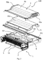
- the ventilation assembly 100 comprisies an air exhaust device 6 for extracting inside air to the exterior, comprising at least one ventilation unit 61 including at least one ventilator 611, 612, 613.
- the ventilation unit or units 61 is/are adapted to be connected to the ventilation device 5 of the roof window 1 so as to provide fluid connection between the interior of the building and the exterior, in the mounted condition.
- the air exhaust device 6 comprises a housing 7 having predefined dimensions and accommodating said at least one ventilation unit 61.
- each ventilation unit 61 includes a flow channel 63 having a first connecting end 63a connected, in a mounted condition, to an inside air inlet 62 in connection with the interior, and a second connecting end 63b connected, in the mounted condition, to a through channel (71).
- the ventilation assembly 100 is positioned above the top member of the window frame 2 as seen in the inclination of the roof.
- the ventilation assembly 100 comprises the housing generally designated 7 and having a cover 70 and two end pieces 70a and 70b.
- the housing 7 is divided in the length direction into a left-hand part and a right-hand part, each accommodating a respective inside air inlet 62, 162.
- the inside air inlets coincide in the center to form a flow channel 63.
- a single ventilation unit 61 is provided in the center.
- the ventilation unit 61 comprises a ventilator 611 which is provided with a power supply (not shown).
- the right-hand part and the left hand part is substantially identical or mirror-images of each other. Air from the inside enters through the ventilation flap 5, through the inside air inlets 62, 162 and travels through the flow channel.
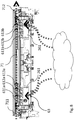
- the housing 7 further comprises the through channel 71 having an ambient air intake end 711 and an air exhaust end 712, the through channel 71 further being connected to said inside air inlet 62 via said flow channel 63 so as to provide said fluid connection between the ventilation device 5 of the roof window 1 and the exterior.
- the air is accelerated through the ventilators towards a through channel 71.
- the through channel 71 is arranged substantially across the ventilation assembly 100.
- the through channel has, at each end, an ambient air intake 711 and an exhaust 712, respectively.
- the through channel 71 thus has a fluid connection from one side to the other of ambient air.
- the through channel 71 has a predefined dimension
- the flow channel 63 has a predefined dimension, causing the air pressure from the air entering the air intake end 711 in cooperation with the at least one ventilator 611, 612, 613 of the ventilation unit 61 to result in a flow of air to be directed from the inside air inlet 62 towards the air exhaust end 712 of the through channel 71 so as to provide a suction action.
- the air intake end 711 and the exhaust end 712 can be on either one of the ends of the through channel, and that the numerals 711 and 712 are schematic.
- the air may travel towards any end. The end towards which the air may flow may depend on the rotating direction of the ventilators.
- the housing in the embodiment shown has a top part 702 and a bottom part 701.
- the top part 702 and the bottom part 701 cooperate in creating the respective channels mentioned 62, 63.
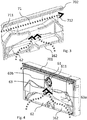
- Figs 1 to 4 The embodiment shown in Figs 1 to 4 is of a type that may be arranged and mounted above the window 1, seen in the direction of the inclination of the roof.
- the ventilation assembly 100 is thus positioned on the outside of the building, and arranged above the window 1.
- the ventilation device is arranged on a top side of the frame 4.
- the top side is here meant the side facing the exterior of a building.
- the ventilation assembly is in this embodiment particularly suited for retrofitting onto an already installed roof window 1.
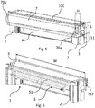
- the length L of the ventilation assembly 100 corresponds in substance to a top casing of the roof window and is arranged in the position of such top casing.
- the roof window system of the embodiment of Figs 5 to 11 may thereby be a slimmer arrangement altogether, and does not require extra space on the roof.
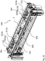
- the ventilation assembly 100 of the embodiment of Figs 5 to 11 comprises a set of two ventilation units 261, 361.
- the ventilation units 261, 361 each comprise a number of ventilators 611a, 612a, 613a and 611b, 612b, 613b, respectively.
- the ventilation assembly 100 may be connected to a moisture sensor, not shown, which may determine at which speed the ventilators rotate.
- each ventilation unit 261, 361 is provided, each including three ventilators 611a, 612a, 613a and 611b, 612b, 613b, respectively.
- a set of inside air inlet channels 262, 362 are provided in the housing 7, which can be seen in Figs 8 to 11 .
- the flow from the ventilation units 61 are both further connected to the through channel 71.
- each ventilation unit 61a, 61b is adapted to be connected to a respective air inlet channel 262, 362 for air intake, and to the ventilation unit 261, 361 to provide a predefined flow path to the through channel 71 to reach ambient air.
- the respective air inlet channels 262, 362 and ventilation units 361, 361 may be isolated from each other and a fluid connection be provided in any suitable manner. However, the through channel 71 may be common for the respective air flows from the respective ventilation unit.
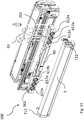
- FIG. 8 Further details of the ventilation assembly 100 are shown in Figs 8 to 11 .
- Fig. 9 it is shown how the ventilation device is arranged to the front of the frame of the window. In this way, the ventilation device may be installed to an already existing window, without the need to cause any damage to the building.
- Power supply to motor 90 is provided by cord 91 which is plugged into the ordinary main supply of the building.
Landscapes
- Engineering & Computer Science (AREA)
- Civil Engineering (AREA)
- Structural Engineering (AREA)
- Chemical & Material Sciences (AREA)
- Combustion & Propulsion (AREA)
- Mechanical Engineering (AREA)
- General Engineering & Computer Science (AREA)
- Architecture (AREA)
- Building Environments (AREA)
- Specific Sealing Or Ventilating Devices For Doors And Windows (AREA)
Priority Applications (1)
| Application Number | Priority Date | Filing Date | Title |
|---|---|---|---|
| EP23179221.9A EP4235045B1 (de) | 2016-10-14 | 2017-10-13 | Dachfenstersystem mit einer lüftungsanordnung mit einer abgasvorrichtung und verfahren zum betrieb einer lüftungsanordnung solch eines dachfenstersystems |
Applications Claiming Priority (1)
| Application Number | Priority Date | Filing Date | Title |
|---|---|---|---|
| DKPA201670807A DK180278B1 (en) | 2016-10-14 | 2016-10-14 | A roof window system comprising a ventilation assembly with an exhaust device |
Related Child Applications (2)
| Application Number | Title | Priority Date | Filing Date |
|---|---|---|---|
| EP23179221.9A Division-Into EP4235045B1 (de) | 2016-10-14 | 2017-10-13 | Dachfenstersystem mit einer lüftungsanordnung mit einer abgasvorrichtung und verfahren zum betrieb einer lüftungsanordnung solch eines dachfenstersystems |
| EP23179221.9A Division EP4235045B1 (de) | 2016-10-14 | 2017-10-13 | Dachfenstersystem mit einer lüftungsanordnung mit einer abgasvorrichtung und verfahren zum betrieb einer lüftungsanordnung solch eines dachfenstersystems |
Publications (3)
| Publication Number | Publication Date |
|---|---|
| EP3309468A2 true EP3309468A2 (de) | 2018-04-18 |
| EP3309468A3 EP3309468A3 (de) | 2018-08-29 |
| EP3309468B1 EP3309468B1 (de) | 2023-07-19 |
Family
ID=60143518
Family Applications (2)
| Application Number | Title | Priority Date | Filing Date |
|---|---|---|---|
| EP23179221.9A Active EP4235045B1 (de) | 2016-10-14 | 2017-10-13 | Dachfenstersystem mit einer lüftungsanordnung mit einer abgasvorrichtung und verfahren zum betrieb einer lüftungsanordnung solch eines dachfenstersystems |
| EP17196345.7A Active EP3309468B1 (de) | 2016-10-14 | 2017-10-13 | Dachfenstersystem mit einer lüftungsanordnung mit einer abgasvorrichtung und verfahren zum betrieb einer lüftungsanordnung solch eines dachfenstersystems |
Family Applications Before (1)
| Application Number | Title | Priority Date | Filing Date |
|---|---|---|---|
| EP23179221.9A Active EP4235045B1 (de) | 2016-10-14 | 2017-10-13 | Dachfenstersystem mit einer lüftungsanordnung mit einer abgasvorrichtung und verfahren zum betrieb einer lüftungsanordnung solch eines dachfenstersystems |
Country Status (4)
| Country | Link |
|---|---|
| EP (2) | EP4235045B1 (de) |
| DK (1) | DK180278B1 (de) |
| ES (1) | ES2956669T3 (de) |
| PL (2) | PL4235045T3 (de) |
Cited By (3)
| Publication number | Priority date | Publication date | Assignee | Title |
|---|---|---|---|---|
| US20210198893A1 (en) * | 2019-12-30 | 2021-07-01 | Vkr Holding A/S | Roof window system with a ventilation unit mounted adjacent to the roof window, a roof structure including a roof window system, a method of providing a roof window system and a method of retrofitting a roof window system |
| EP3845718A1 (de) | 2019-12-30 | 2021-07-07 | VKR Holding A/S | Dachfenstersystem mit einer neben dem dachfenster montierten lüftungseinheit und verfahren zur belüftung eines gebäudes |
| EP4283069A1 (de) * | 2022-05-27 | 2023-11-29 | Keylite Roof Windows Limited | Haube für ein dachfenster |
Family Cites Families (17)
| Publication number | Priority date | Publication date | Assignee | Title |
|---|---|---|---|---|
| US657949A (en) * | 1899-09-15 | 1900-09-18 | Claes Oscar Meurk | Window-ventilator. |
| US792990A (en) * | 1904-04-05 | 1905-06-20 | James Hough | Ventilator. |
| GB162405A (en) * | 1920-02-02 | 1921-05-02 | Henry Ismay Moralee Ross | Improved exhaust ventilators |
| DK165255C (da) | 1988-11-11 | 1993-03-08 | Rasmussen Kann Ind As | Tagvindue og storrumsvinduesinstallation med et antal saadanne vinduer |
| DK164964C (da) * | 1990-05-23 | 1993-02-08 | Rasmussen Kann Ind As | Vindue med mekanisk ventilation |
| DE9206729U1 (de) | 1992-02-03 | 1993-06-03 | Berner, Erling, Zug | Vorrichtung zum Umkehren einer Luftströmung innerhalb eines Schachts |
| DE19811469A1 (de) | 1998-03-17 | 1999-09-30 | Rehfus Bernd | Apparat zur Be- und Entlüftung von Räumen mit einem regenerativen Wärmetauscher |
| DK200001472A (da) | 2000-10-04 | 2002-04-05 | Vkr Holding As | Vindue med ventilationsåbninger |
| DE202004020630U1 (de) | 2004-08-03 | 2006-01-26 | Boden, Christian | Dachfensterintegriertes Solar-Lüftungssystem |
| DE102004037563A1 (de) | 2004-08-03 | 2006-03-16 | Christian Boden | Dachfensterintegriertes Solar-Lüftungssystem |
| DK176947B1 (da) | 2007-12-03 | 2010-06-21 | Form & Plast As | Friskluftventil |
| GB2474529B (en) * | 2010-03-10 | 2011-09-21 | Green Structures Ltd | Ventilation system |
| WO2013050039A1 (en) | 2011-10-04 | 2013-04-11 | Vkr Holding A/S | A roof window with a top sash module |
| KR20130106008A (ko) * | 2012-03-19 | 2013-09-27 | (주)엘지하우시스 | 저소음 열교환 창호시스템 |
| KR101433437B1 (ko) * | 2012-03-19 | 2014-08-27 | (주)엘지하우시스 | 창호용 환기장치 |
| DK179084B1 (en) * | 2013-03-12 | 2017-10-16 | Vkr Holding As | A roof window system comprising a ventilation assembly and method of operating such a ventilation assembly |
| DE202016100906U1 (de) * | 2016-02-19 | 2016-07-05 | Vkr Holding A/S | Dachfenstersystem mit einem Dachfenster und einem Belüftungsaufbau |
-
2016
- 2016-10-14 DK DKPA201670807A patent/DK180278B1/en active IP Right Grant
-
2017
- 2017-10-13 ES ES17196345T patent/ES2956669T3/es active Active
- 2017-10-13 PL PL23179221.9T patent/PL4235045T3/pl unknown
- 2017-10-13 EP EP23179221.9A patent/EP4235045B1/de active Active
- 2017-10-13 PL PL17196345.7T patent/PL3309468T3/pl unknown
- 2017-10-13 EP EP17196345.7A patent/EP3309468B1/de active Active
Cited By (7)
| Publication number | Priority date | Publication date | Assignee | Title |
|---|---|---|---|---|
| US20210198893A1 (en) * | 2019-12-30 | 2021-07-01 | Vkr Holding A/S | Roof window system with a ventilation unit mounted adjacent to the roof window, a roof structure including a roof window system, a method of providing a roof window system and a method of retrofitting a roof window system |
| EP3845719A1 (de) * | 2019-12-30 | 2021-07-07 | VKR Holding A/S | Dachfenstersystem mit einer neben dem dachfenster montierten lüftungseinheit, dachstruktur mit einem dachfenstersystem, verfahren zur herstellung eines dachfenstersystems und verfahren zum nachrüsten eines dachfenstersystems |
| EP3845718A1 (de) | 2019-12-30 | 2021-07-07 | VKR Holding A/S | Dachfenstersystem mit einer neben dem dachfenster montierten lüftungseinheit und verfahren zur belüftung eines gebäudes |
| US11686096B2 (en) | 2019-12-30 | 2023-06-27 | Vkr Holding A/S | Roof window system with a ventilation unit mounted adjacent to the roof window, a roof structure including a roof window system, a method of providing a roof window system and a method of retrofitting a roof window system |
| US11834832B2 (en) | 2019-12-30 | 2023-12-05 | Vkr Holding A/S | Roof window system with a ventilation unit mounted adjacent to the roof window, and a method of providing ventilation for a building |
| US11993934B2 (en) | 2019-12-30 | 2024-05-28 | Vkr Holding A/S | Roof window system with a ventilation unit mounted adjacent to the roof window, a roof structure including a roof window system, a method of providing a roof window system and a method of retrofitting a roof window system |
| EP4283069A1 (de) * | 2022-05-27 | 2023-11-29 | Keylite Roof Windows Limited | Haube für ein dachfenster |
Also Published As
| Publication number | Publication date |
|---|---|
| DK180278B1 (en) | 2020-09-25 |
| ES2956669T3 (es) | 2023-12-26 |
| EP3309468B1 (de) | 2023-07-19 |
| PL3309468T3 (pl) | 2024-01-03 |
| EP4235045B1 (de) | 2025-08-06 |
| PL4235045T3 (pl) | 2025-12-01 |
| EP4235045A2 (de) | 2023-08-30 |
| DK201670807A1 (en) | 2018-05-07 |
| EP3309468A3 (de) | 2018-08-29 |
| EP4235045A3 (de) | 2024-01-03 |
Similar Documents
| Publication | Publication Date | Title |
|---|---|---|
| EP3309468B1 (de) | Dachfenstersystem mit einer lüftungsanordnung mit einer abgasvorrichtung und verfahren zum betrieb einer lüftungsanordnung solch eines dachfenstersystems | |
| NO830029L (no) | Ventilasjonsinnretning. | |
| CN113123538A (zh) | 具有邻近于屋顶窗户安装的通风单元的屋顶窗户系统、以及为建筑物提供通风的方法 | |
| EP3901404B1 (de) | Dachfenstersystem mit einer lüftungsanordnung und verfahren zur belüftung | |
| US11993934B2 (en) | Roof window system with a ventilation unit mounted adjacent to the roof window, a roof structure including a roof window system, a method of providing a roof window system and a method of retrofitting a roof window system | |
| EP2784240A2 (de) | Dachfenstersystem mit einem Dachfenster und Lüftereinheit, und Verfahren zum Betrieb der Entlüftungsanordnung im Dachfenster | |
| KR102087826B1 (ko) | 창문 설치용 환기장치 | |
| KR100893073B1 (ko) | 발코니 결로 방지 기능이 통합된 욕실 환기 시스템 | |
| KR101884398B1 (ko) | 열회수 환기장치 | |
| EP3348736B1 (de) | Dachfenstersystem mit einer entlüftungsanordnung mit verbessertem strömungsweg und verfahren zum betrieb der entlüftungsanordnung | |
| KR101923600B1 (ko) | 자연채광을 도모할 수 있는 공동주택용 폴딩도어 | |
| KR100916848B1 (ko) | 자연 환기장치 | |
| KR100548927B1 (ko) | 환기시스템의 점검도어 장착구조 | |
| KR20060098281A (ko) | 환기시스템 | |
| JP5351716B2 (ja) | 建物の通気システム | |
| KR200424327Y1 (ko) | 환기장치 | |
| JP2016065647A (ja) | 換気扇装置およびこの換気扇装置を備えた建物 | |
| KR900009905Y1 (ko) | 환기창 겸용 벤츄레이터 | |
| KR100763418B1 (ko) | 환기장치 | |
| JP3978676B2 (ja) | 窓換気装置 | |
| JP2005164130A (ja) | 自然給気口 | |
| KR20230039323A (ko) | 외풍 유입 가이드장치 | |
| JP2005273177A (ja) | 窓換気装置及びこれを備えた浴室 | |
| JPH05118599A (ja) | 室内換気用給気口構造 | |
| WO2011092530A1 (en) | System of heat-degradation diminishing air-exchanger and air-purifier combined with openings |
Legal Events
| Date | Code | Title | Description |
|---|---|---|---|
| PUAI | Public reference made under article 153(3) epc to a published international application that has entered the european phase |
Free format text: ORIGINAL CODE: 0009012 |
|
| STAA | Information on the status of an ep patent application or granted ep patent |
Free format text: STATUS: THE APPLICATION HAS BEEN PUBLISHED |
|
| AK | Designated contracting states |
Kind code of ref document: A2 Designated state(s): AL AT BE BG CH CY CZ DE DK EE ES FI FR GB GR HR HU IE IS IT LI LT LU LV MC MK MT NL NO PL PT RO RS SE SI SK SM TR |
|
| AX | Request for extension of the european patent |
Extension state: BA ME |
|
| PUAL | Search report despatched |
Free format text: ORIGINAL CODE: 0009013 |
|
| AK | Designated contracting states |
Kind code of ref document: A3 Designated state(s): AL AT BE BG CH CY CZ DE DK EE ES FI FR GB GR HR HU IE IS IT LI LT LU LV MC MK MT NL NO PL PT RO RS SE SI SK SM TR |
|
| AX | Request for extension of the european patent |
Extension state: BA ME |
|
| RIC1 | Information provided on ipc code assigned before grant |
Ipc: F24F 13/18 20060101ALI20180720BHEP Ipc: F24F 7/08 20060101ALI20180720BHEP Ipc: E06B 7/10 20060101ALI20180720BHEP Ipc: E04D 13/03 20060101ALI20180720BHEP Ipc: F24F 7/02 20060101AFI20180720BHEP |
|
| STAA | Information on the status of an ep patent application or granted ep patent |
Free format text: STATUS: REQUEST FOR EXAMINATION WAS MADE |
|
| 17P | Request for examination filed |
Effective date: 20190221 |
|
| RBV | Designated contracting states (corrected) |
Designated state(s): AL AT BE BG CH CY CZ DE DK EE ES FI FR GB GR HR HU IE IS IT LI LT LU LV MC MK MT NL NO PL PT RO RS SE SI SK SM TR |
|
| STAA | Information on the status of an ep patent application or granted ep patent |
Free format text: STATUS: EXAMINATION IS IN PROGRESS |
|
| 17Q | First examination report despatched |
Effective date: 20201007 |
|
| GRAP | Despatch of communication of intention to grant a patent |
Free format text: ORIGINAL CODE: EPIDOSNIGR1 |
|
| STAA | Information on the status of an ep patent application or granted ep patent |
Free format text: STATUS: GRANT OF PATENT IS INTENDED |
|
| INTG | Intention to grant announced |
Effective date: 20230315 |
|
| GRAS | Grant fee paid |
Free format text: ORIGINAL CODE: EPIDOSNIGR3 |
|
| GRAA | (expected) grant |
Free format text: ORIGINAL CODE: 0009210 |
|
| STAA | Information on the status of an ep patent application or granted ep patent |
Free format text: STATUS: THE PATENT HAS BEEN GRANTED |
|
| AK | Designated contracting states |
Kind code of ref document: B1 Designated state(s): AL AT BE BG CH CY CZ DE DK EE ES FI FR GB GR HR HU IE IS IT LI LT LU LV MC MK MT NL NO PL PT RO RS SE SI SK SM TR |
|
| REG | Reference to a national code |
Ref country code: GB Ref legal event code: FG4D |
|
| REG | Reference to a national code |
Ref country code: CH Ref legal event code: EP |
|
| REG | Reference to a national code |
Ref country code: DE Ref legal event code: R096 Ref document number: 602017071421 Country of ref document: DE |
|
| REG | Reference to a national code |
Ref country code: IE Ref legal event code: FG4D |
|
| REG | Reference to a national code |
Ref country code: NL Ref legal event code: FP |
|
| REG | Reference to a national code |
Ref country code: LT Ref legal event code: MG9D |
|
| REG | Reference to a national code |
Ref country code: ES Ref legal event code: FG2A Ref document number: 2956669 Country of ref document: ES Kind code of ref document: T3 Effective date: 20231226 |
|
| PG25 | Lapsed in a contracting state [announced via postgrant information from national office to epo] |
Ref country code: GR Free format text: LAPSE BECAUSE OF FAILURE TO SUBMIT A TRANSLATION OF THE DESCRIPTION OR TO PAY THE FEE WITHIN THE PRESCRIBED TIME-LIMIT Effective date: 20231020 |
|
| PG25 | Lapsed in a contracting state [announced via postgrant information from national office to epo] |
Ref country code: IS Free format text: LAPSE BECAUSE OF FAILURE TO SUBMIT A TRANSLATION OF THE DESCRIPTION OR TO PAY THE FEE WITHIN THE PRESCRIBED TIME-LIMIT Effective date: 20231119 |
|
| PG25 | Lapsed in a contracting state [announced via postgrant information from national office to epo] |
Ref country code: SE Free format text: LAPSE BECAUSE OF FAILURE TO SUBMIT A TRANSLATION OF THE DESCRIPTION OR TO PAY THE FEE WITHIN THE PRESCRIBED TIME-LIMIT Effective date: 20230719 Ref country code: RS Free format text: LAPSE BECAUSE OF FAILURE TO SUBMIT A TRANSLATION OF THE DESCRIPTION OR TO PAY THE FEE WITHIN THE PRESCRIBED TIME-LIMIT Effective date: 20230719 Ref country code: PT Free format text: LAPSE BECAUSE OF FAILURE TO SUBMIT A TRANSLATION OF THE DESCRIPTION OR TO PAY THE FEE WITHIN THE PRESCRIBED TIME-LIMIT Effective date: 20231120 Ref country code: NO Free format text: LAPSE BECAUSE OF FAILURE TO SUBMIT A TRANSLATION OF THE DESCRIPTION OR TO PAY THE FEE WITHIN THE PRESCRIBED TIME-LIMIT Effective date: 20231019 Ref country code: LV Free format text: LAPSE BECAUSE OF FAILURE TO SUBMIT A TRANSLATION OF THE DESCRIPTION OR TO PAY THE FEE WITHIN THE PRESCRIBED TIME-LIMIT Effective date: 20230719 Ref country code: LT Free format text: LAPSE BECAUSE OF FAILURE TO SUBMIT A TRANSLATION OF THE DESCRIPTION OR TO PAY THE FEE WITHIN THE PRESCRIBED TIME-LIMIT Effective date: 20230719 Ref country code: IS Free format text: LAPSE BECAUSE OF FAILURE TO SUBMIT A TRANSLATION OF THE DESCRIPTION OR TO PAY THE FEE WITHIN THE PRESCRIBED TIME-LIMIT Effective date: 20231119 Ref country code: HR Free format text: LAPSE BECAUSE OF FAILURE TO SUBMIT A TRANSLATION OF THE DESCRIPTION OR TO PAY THE FEE WITHIN THE PRESCRIBED TIME-LIMIT Effective date: 20230719 Ref country code: GR Free format text: LAPSE BECAUSE OF FAILURE TO SUBMIT A TRANSLATION OF THE DESCRIPTION OR TO PAY THE FEE WITHIN THE PRESCRIBED TIME-LIMIT Effective date: 20231020 Ref country code: FI Free format text: LAPSE BECAUSE OF FAILURE TO SUBMIT A TRANSLATION OF THE DESCRIPTION OR TO PAY THE FEE WITHIN THE PRESCRIBED TIME-LIMIT Effective date: 20230719 |
|
| REG | Reference to a national code |
Ref country code: AT Ref legal event code: UEP Ref document number: 1589820 Country of ref document: AT Kind code of ref document: T Effective date: 20230719 |
|
| REG | Reference to a national code |
Ref country code: DE Ref legal event code: R097 Ref document number: 602017071421 Country of ref document: DE |
|
| PG25 | Lapsed in a contracting state [announced via postgrant information from national office to epo] |
Ref country code: SM Free format text: LAPSE BECAUSE OF FAILURE TO SUBMIT A TRANSLATION OF THE DESCRIPTION OR TO PAY THE FEE WITHIN THE PRESCRIBED TIME-LIMIT Effective date: 20230719 Ref country code: RO Free format text: LAPSE BECAUSE OF FAILURE TO SUBMIT A TRANSLATION OF THE DESCRIPTION OR TO PAY THE FEE WITHIN THE PRESCRIBED TIME-LIMIT Effective date: 20230719 Ref country code: EE Free format text: LAPSE BECAUSE OF FAILURE TO SUBMIT A TRANSLATION OF THE DESCRIPTION OR TO PAY THE FEE WITHIN THE PRESCRIBED TIME-LIMIT Effective date: 20230719 Ref country code: DK Free format text: LAPSE BECAUSE OF FAILURE TO SUBMIT A TRANSLATION OF THE DESCRIPTION OR TO PAY THE FEE WITHIN THE PRESCRIBED TIME-LIMIT Effective date: 20230719 Ref country code: CZ Free format text: LAPSE BECAUSE OF FAILURE TO SUBMIT A TRANSLATION OF THE DESCRIPTION OR TO PAY THE FEE WITHIN THE PRESCRIBED TIME-LIMIT Effective date: 20230719 Ref country code: SK Free format text: LAPSE BECAUSE OF FAILURE TO SUBMIT A TRANSLATION OF THE DESCRIPTION OR TO PAY THE FEE WITHIN THE PRESCRIBED TIME-LIMIT Effective date: 20230719 |
|
| PLBE | No opposition filed within time limit |
Free format text: ORIGINAL CODE: 0009261 |
|
| STAA | Information on the status of an ep patent application or granted ep patent |
Free format text: STATUS: NO OPPOSITION FILED WITHIN TIME LIMIT |
|
| PG25 | Lapsed in a contracting state [announced via postgrant information from national office to epo] |
Ref country code: MC Free format text: LAPSE BECAUSE OF FAILURE TO SUBMIT A TRANSLATION OF THE DESCRIPTION OR TO PAY THE FEE WITHIN THE PRESCRIBED TIME-LIMIT Effective date: 20230719 |
|
| PG25 | Lapsed in a contracting state [announced via postgrant information from national office to epo] |
Ref country code: LU Free format text: LAPSE BECAUSE OF NON-PAYMENT OF DUE FEES Effective date: 20231013 |
|
| 26N | No opposition filed |
Effective date: 20240422 |
|
| PG25 | Lapsed in a contracting state [announced via postgrant information from national office to epo] |
Ref country code: LU Free format text: LAPSE BECAUSE OF NON-PAYMENT OF DUE FEES Effective date: 20231013 |
|
| PG25 | Lapsed in a contracting state [announced via postgrant information from national office to epo] |
Ref country code: SI Free format text: LAPSE BECAUSE OF FAILURE TO SUBMIT A TRANSLATION OF THE DESCRIPTION OR TO PAY THE FEE WITHIN THE PRESCRIBED TIME-LIMIT Effective date: 20230719 |
|
| PG25 | Lapsed in a contracting state [announced via postgrant information from national office to epo] |
Ref country code: IE Free format text: LAPSE BECAUSE OF NON-PAYMENT OF DUE FEES Effective date: 20231013 |
|
| PG25 | Lapsed in a contracting state [announced via postgrant information from national office to epo] |
Ref country code: IE Free format text: LAPSE BECAUSE OF NON-PAYMENT OF DUE FEES Effective date: 20231013 |
|
| PG25 | Lapsed in a contracting state [announced via postgrant information from national office to epo] |
Ref country code: BG Free format text: LAPSE BECAUSE OF FAILURE TO SUBMIT A TRANSLATION OF THE DESCRIPTION OR TO PAY THE FEE WITHIN THE PRESCRIBED TIME-LIMIT Effective date: 20230719 |
|
| PG25 | Lapsed in a contracting state [announced via postgrant information from national office to epo] |
Ref country code: BG Free format text: LAPSE BECAUSE OF FAILURE TO SUBMIT A TRANSLATION OF THE DESCRIPTION OR TO PAY THE FEE WITHIN THE PRESCRIBED TIME-LIMIT Effective date: 20230719 |
|
| PG25 | Lapsed in a contracting state [announced via postgrant information from national office to epo] |
Ref country code: CY Free format text: LAPSE BECAUSE OF FAILURE TO SUBMIT A TRANSLATION OF THE DESCRIPTION OR TO PAY THE FEE WITHIN THE PRESCRIBED TIME-LIMIT; INVALID AB INITIO Effective date: 20171013 |
|
| PG25 | Lapsed in a contracting state [announced via postgrant information from national office to epo] |
Ref country code: HU Free format text: LAPSE BECAUSE OF FAILURE TO SUBMIT A TRANSLATION OF THE DESCRIPTION OR TO PAY THE FEE WITHIN THE PRESCRIBED TIME-LIMIT; INVALID AB INITIO Effective date: 20171013 |
|
| PGFP | Annual fee paid to national office [announced via postgrant information from national office to epo] |
Ref country code: PL Payment date: 20250912 Year of fee payment: 9 Ref country code: NL Payment date: 20250912 Year of fee payment: 9 Ref country code: IT Payment date: 20250922 Year of fee payment: 9 |
|
| PGFP | Annual fee paid to national office [announced via postgrant information from national office to epo] |
Ref country code: BE Payment date: 20250917 Year of fee payment: 9 Ref country code: GB Payment date: 20250904 Year of fee payment: 9 |
|
| PGFP | Annual fee paid to national office [announced via postgrant information from national office to epo] |
Ref country code: FR Payment date: 20250908 Year of fee payment: 9 |
|
| REG | Reference to a national code |
Ref country code: CH Ref legal event code: U11 Free format text: ST27 STATUS EVENT CODE: U-0-0-U10-U11 (AS PROVIDED BY THE NATIONAL OFFICE) Effective date: 20251101 |
|
| PG25 | Lapsed in a contracting state [announced via postgrant information from national office to epo] |
Ref country code: TR Free format text: LAPSE BECAUSE OF FAILURE TO SUBMIT A TRANSLATION OF THE DESCRIPTION OR TO PAY THE FEE WITHIN THE PRESCRIBED TIME-LIMIT Effective date: 20230719 |
|
| PGFP | Annual fee paid to national office [announced via postgrant information from national office to epo] |
Ref country code: DE Payment date: 20250902 Year of fee payment: 9 |
|
| PGFP | Annual fee paid to national office [announced via postgrant information from national office to epo] |
Ref country code: AT Payment date: 20250925 Year of fee payment: 9 |
|
| PGFP | Annual fee paid to national office [announced via postgrant information from national office to epo] |
Ref country code: CH Payment date: 20251101 Year of fee payment: 9 |
|
| PGFP | Annual fee paid to national office [announced via postgrant information from national office to epo] |
Ref country code: ES Payment date: 20251104 Year of fee payment: 9 |