EP3309927B1 - Équilibreur de bus à liaison cc - Google Patents
Équilibreur de bus à liaison cc Download PDFInfo
- Publication number
- EP3309927B1 EP3309927B1 EP17195374.8A EP17195374A EP3309927B1 EP 3309927 B1 EP3309927 B1 EP 3309927B1 EP 17195374 A EP17195374 A EP 17195374A EP 3309927 B1 EP3309927 B1 EP 3309927B1
- Authority
- EP
- European Patent Office
- Prior art keywords
- bus
- level
- positive
- negative
- mode
- Prior art date
- Legal status (The legal status is an assumption and is not a legal conclusion. Google has not performed a legal analysis and makes no representation as to the accuracy of the status listed.)
- Active
Links
Images


Classifications
-
- H—ELECTRICITY
- H02—GENERATION; CONVERSION OR DISTRIBUTION OF ELECTRIC POWER
- H02J—ELECTRIC POWER NETWORKS; CIRCUIT ARRANGEMENTS OR SYSTEMS FOR SUPPLYING OR DISTRIBUTING ELECTRIC POWER; SYSTEMS FOR STORING ELECTRIC ENERGY
- H02J9/00—Circuit arrangements for emergency or stand-by power supply, e.g. for emergency lighting
- H02J9/04—Circuit arrangements for emergency or stand-by power supply, e.g. for emergency lighting in which the distribution system is disconnected from the normal source and connected to a standby source
- H02J9/06—Circuit arrangements for emergency or stand-by power supply, e.g. for emergency lighting in which the distribution system is disconnected from the normal source and connected to a standby source with automatic change-over, e.g. UPS systems
- H02J9/062—Circuit arrangements for emergency or stand-by power supply, e.g. for emergency lighting in which the distribution system is disconnected from the normal source and connected to a standby source with automatic change-over, e.g. UPS systems for AC powered loads
-
- H—ELECTRICITY
- H02—GENERATION; CONVERSION OR DISTRIBUTION OF ELECTRIC POWER
- H02M—APPARATUS FOR CONVERSION BETWEEN AC AND AC, BETWEEN AC AND DC, OR BETWEEN DC AND DC, AND FOR USE WITH MAINS OR SIMILAR POWER SUPPLY SYSTEMS; CONVERSION OF DC OR AC INPUT POWER INTO SURGE OUTPUT POWER; CONTROL OR REGULATION THEREOF
- H02M5/00—Conversion of AC power input into AC power output, e.g. for change of voltage, for change of frequency, for change of number of phases
- H02M5/40—Conversion of AC power input into AC power output, e.g. for change of voltage, for change of frequency, for change of number of phases with intermediate conversion into DC
- H02M5/42—Conversion of AC power input into AC power output, e.g. for change of voltage, for change of frequency, for change of number of phases with intermediate conversion into DC by static converters
- H02M5/44—Conversion of AC power input into AC power output, e.g. for change of voltage, for change of frequency, for change of number of phases with intermediate conversion into DC by static converters using discharge tubes or semiconductor devices to convert the intermediate DC into AC
- H02M5/453—Conversion of AC power input into AC power output, e.g. for change of voltage, for change of frequency, for change of number of phases with intermediate conversion into DC by static converters using discharge tubes or semiconductor devices to convert the intermediate DC into AC using devices of a triode or transistor type requiring continuous application of a control signal
- H02M5/458—Conversion of AC power input into AC power output, e.g. for change of voltage, for change of frequency, for change of number of phases with intermediate conversion into DC by static converters using discharge tubes or semiconductor devices to convert the intermediate DC into AC using devices of a triode or transistor type requiring continuous application of a control signal using semiconductor devices only
- H02M5/4585—Conversion of AC power input into AC power output, e.g. for change of voltage, for change of frequency, for change of number of phases with intermediate conversion into DC by static converters using discharge tubes or semiconductor devices to convert the intermediate DC into AC using devices of a triode or transistor type requiring continuous application of a control signal using semiconductor devices only having a rectifier with controlled elements
-
- H—ELECTRICITY
- H02—GENERATION; CONVERSION OR DISTRIBUTION OF ELECTRIC POWER
- H02M—APPARATUS FOR CONVERSION BETWEEN AC AND AC, BETWEEN AC AND DC, OR BETWEEN DC AND DC, AND FOR USE WITH MAINS OR SIMILAR POWER SUPPLY SYSTEMS; CONVERSION OF DC OR AC INPUT POWER INTO SURGE OUTPUT POWER; CONTROL OR REGULATION THEREOF
- H02M7/00—Conversion of AC power input into DC power output; Conversion of DC power input into AC power output
- H02M7/42—Conversion of DC power input into AC power output without possibility of reversal
- H02M7/44—Conversion of DC power input into AC power output without possibility of reversal by static converters
- H02M7/48—Conversion of DC power input into AC power output without possibility of reversal by static converters using discharge tubes with control electrode or semiconductor devices with control electrode
- H02M7/483—Converters with outputs that each can have more than two voltages levels
- H02M7/487—Neutral point clamped inverters
-
- H—ELECTRICITY
- H02—GENERATION; CONVERSION OR DISTRIBUTION OF ELECTRIC POWER
- H02M—APPARATUS FOR CONVERSION BETWEEN AC AND AC, BETWEEN AC AND DC, OR BETWEEN DC AND DC, AND FOR USE WITH MAINS OR SIMILAR POWER SUPPLY SYSTEMS; CONVERSION OF DC OR AC INPUT POWER INTO SURGE OUTPUT POWER; CONTROL OR REGULATION THEREOF
- H02M7/00—Conversion of AC power input into DC power output; Conversion of DC power input into AC power output
- H02M7/42—Conversion of DC power input into AC power output without possibility of reversal
- H02M7/44—Conversion of DC power input into AC power output without possibility of reversal by static converters
- H02M7/48—Conversion of DC power input into AC power output without possibility of reversal by static converters using discharge tubes with control electrode or semiconductor devices with control electrode
- H02M7/53—Conversion of DC power input into AC power output without possibility of reversal by static converters using discharge tubes with control electrode or semiconductor devices with control electrode using devices of a triode or transistor type requiring continuous application of a control signal
- H02M7/537—Conversion of DC power input into AC power output without possibility of reversal by static converters using discharge tubes with control electrode or semiconductor devices with control electrode using devices of a triode or transistor type requiring continuous application of a control signal using semiconductor devices only, e.g. single switched pulse inverters
- H02M7/539—Conversion of DC power input into AC power output without possibility of reversal by static converters using discharge tubes with control electrode or semiconductor devices with control electrode using devices of a triode or transistor type requiring continuous application of a control signal using semiconductor devices only, e.g. single switched pulse inverters with automatic control of output wave form or frequency
- H02M7/5395—Conversion of DC power input into AC power output without possibility of reversal by static converters using discharge tubes with control electrode or semiconductor devices with control electrode using devices of a triode or transistor type requiring continuous application of a control signal using semiconductor devices only, e.g. single switched pulse inverters with automatic control of output wave form or frequency by pulse-width modulation
-
- H—ELECTRICITY
- H02—GENERATION; CONVERSION OR DISTRIBUTION OF ELECTRIC POWER
- H02J—ELECTRIC POWER NETWORKS; CIRCUIT ARRANGEMENTS OR SYSTEMS FOR SUPPLYING OR DISTRIBUTING ELECTRIC POWER; SYSTEMS FOR STORING ELECTRIC ENERGY
- H02J9/00—Circuit arrangements for emergency or stand-by power supply, e.g. for emergency lighting
- H02J9/04—Circuit arrangements for emergency or stand-by power supply, e.g. for emergency lighting in which the distribution system is disconnected from the normal source and connected to a standby source
- H02J9/06—Circuit arrangements for emergency or stand-by power supply, e.g. for emergency lighting in which the distribution system is disconnected from the normal source and connected to a standby source with automatic change-over, e.g. UPS systems
- H02J9/062—Circuit arrangements for emergency or stand-by power supply, e.g. for emergency lighting in which the distribution system is disconnected from the normal source and connected to a standby source with automatic change-over, e.g. UPS systems for AC powered loads
- H02J9/063—Common neutral, e.g. AC input neutral line connected to AC output neutral line and DC middle point
Definitions
- the present invention relates generally to systems and methods for controlling an uninterruptible power supply (UPS).
- UPS uninterruptible power supply
- UPS uninterruptible power supplies
- Known uninterruptible power supplies include on-line UPS's, off-line UPS's, line interactive UPS's as well as others.
- On-line UPS's provide conditioned AC power as well as back-up AC power upon interruption of a primary source of AC power.
- Off-line UPS's typically do not provide conditioning of input AC power, but do provide back-up AC power upon interruption of the primary AC power source.
- Line interactive UPS's are similar to off-line UPS's in that they switch to battery power when a blackout occurs but also typically include a multi-tap transformer for regulating the output voltage provided by the UPS.
- the present invention is directed to an Uninterruptible Power Supply (UPS) system according to claim 1 and to a method of operating an Uninterruptible Power Supply (UPS) according to claim 13.
- Embodiments of the invention are defined in the dependent claims.
- At least one aspect of the invention is directed to an Uninterruptible Power Supply (UPS) system, the UPS system comprising an input configured to be coupled to an AC source and to receive input AC power from the AC source, an output configured to provide output AC power to a load, a converter coupled to the input and configured to convert the input power into DC power having a positive DC voltage level and a negative DC voltage level, a plurality of DC busses coupled to the converter and configured to receive the DC power from the converter, the plurality of DC busses including a positive DC bus configured to maintain the positive DC voltage level, a mid-point DC bus, and a negative DC bus configured to maintain the negative DC voltage, a 3-level inverter coupled to the plurality of DC busses and configured to convert the DC power from the plurality of DC buses into
- the controller in selectively controlling the 3-level inverter to operate in the 2-level mode of operation and the 3-level mode of operation, is further configured to operate the 3-level inverter, during a positive half-period of a line cycle, in the 2-level mode of operation to transfer energy from the positive DC bus to the negative DC bus.
- the controller in operating the 3-level inverter, during the positive half-period of the line cycle, in the 2-level mode of operation to transfer energy from the positive DC bus to the negative DC bus, the controller is further configured to operate the 3-level inverter in the 2-level mode of operation for a portion of the positive half-period. In one embodiment, in operating the 3-level inverter, during the positive half-period of the line cycle, in the 2-level mode of operation to transfer energy from the positive DC bus to the negative DC bus, the controller is further configured to operate the 3-level inverter to alternate between the 2-level mode of operation and the 3-level mode of operation during the positive half-period.
- the controller in operating the 3-level inverter, during the positive half-period of the line cycle, in the 2-level mode of operation to transfer energy from the positive DC bus to the negative DC bus, the controller is further configured to operate the 3-level inverter in the 2-level mode of operation for the entire positive half-period. In one embodiment, in selectively controlling the 3-level inverter to operate in the 2-level mode of operation and the 3-level mode of operation, the controller is further configured to operate the 3-level inverter, during a negative half-period of the line cycle, in the 2-level mode of operation to transfer energy from the negative DC bus to the positive DC bus.
- the 3-level inverter comprises a plurality of switches coupled between the plurality of DC busses, and wherein in selectively controlling the 3-level inverter to operate in the 2-level mode of operation and the 3-level mode of operation, the controller is further configured to control the plurality of switches to operate, in a first mode of operation, to generate a first current path that draws energy from the positive DC bus and boosts current through the output, operate, in a second mode of operation, to generate a second current path between the mid-point DC bus and the output, and operate, in a third mode of operation, to generate a third current path that delivers energy to the negative DC bus 110.
- the plurality of switches includes a first switch coupled between the positive DC bus and the output, a second switch coupled between the negative DC bus and the output, a third switch coupled to mid-point DC bus, and a fourth switch coupled between the third switch and the output.
- the controller in operating the plurality of switches in the first mode of operation, is further configured to control the first switch to close to couple the positive DC bus to the output via the first switch.
- the UPS system further comprises a first capacitor coupled between the mid-point bus and the positive DC bus.
- the controller in operating the plurality of switches in the second mode of operation, the controller is further configured to control the third switch and the fourth switch to close to couple the mid-point DC bus to the output via the third switch and the fourth switch.
- the controller in operating the plurality of switches in the third mode of operation, is further configured to control the second switch to couple the negative DC bus to the output via the second switch.
- the UPS system further comprises a second capacitor coupled between the mid-point bus and the negative DC bus.
- the converter is further configured to receive 3-phase input AC power from the AC source and convert the 3-phase input AC power into the DC power.
- the 3-level inverter if further configured to convert the DC power from the plurality of DC buses into 3-phase output AC power and provide the 3-phase AC power to the output.
- Another aspect of the invention is directed to a method for operating a UPS comprising an input configured to be coupled to a power source, an output, a plurality of DC buses including a positive DC bus, a mid-point DC bus, and a negative DC bus, and a 3-level inverter coupled to the plurality of DC busses, the method comprising receiving input power from the power source, maintaining a positive DC voltage level on the positive DC bus, maintaining a negative DC voltage level on the negative DC bus, converting, with the 3-level inverter, the DC power from the plurality of DC buses into output AC power, providing the output AC power to the output, monitoring the positive DC voltage level and the negative DC voltage level, identifying an imbalance between the positive DC voltage level and the negative DC voltage level, and selectively controlling, based on the imbalance, the 3-level inverter to operate in a 2-level mode of operation and a 3-level mode of operation to transfer energy between the positive DC bus and the negative DC bus.
- selectively controlling the 3-level inverter to operate in the 2-level mode of operation and the 3-level mode of operation includes operating the 3-level inverter, during a positive half-period of a line cycle, in the 2-level mode of operation to transfer energy from the positive DC bus to the negative DC bus, and operating the 3-level inverter, during a negative half-period of the line cycle, in the 2-level mode of operation to transfer energy from the negative DC bus to the positive DC bus.
- the UPS further comprises a plurality of switches coupled between the DC busses, and wherein operating the 3-level inverter, during the positive half-period of the line cycle, in the 2-level mode of operation to transfer energy from the positive DC bus to the negative DC bus includes operating, in a first mode of operation, the plurality of switches to boost output current of the 3-level inverter, operating, in a second mode of operation, the plurality of switches to free-wheel current in the mid-point DC bus, and operating, in a third mode of operation, the plurality of switches to free-wheel current in the negative DC bus, transferring energy from the positive DC bus to the negative DC bus.
- At least one aspect of the invention is directed to an Uninterruptible Power Supply (UPS) system, the UPS system comprising an input configured to be coupled to a power source and to receive input power from the power source, an output configured to provide output AC power to a load, a converter coupled to the input and configured to convert the input power into DC power having a positive DC voltage level and a negative DC voltage level, a plurality of DC busses coupled to the converter and configured to receive the DC power from the converter, the plurality of DC busses including a positive DC bus configured to maintain the positive DC voltage level, a mid-point DC bus, and a negative DC bus configured to maintain the negative DC voltage level, and means for converting the DC power from the plurality of DC buses into the output AC power, for providing the output AC Power to the output, and for balancing the positive DC voltage level on the positive DC bus with the negative DC voltage level on the negative DC bus.
- UPS Uninterruptible Power Supply
- references to "or” may be construed as inclusive so that any terms described using “or” may indicate any of a single, more than one, and all of the described terms.
- the term usage in the incorporated references is supplementary to that of this document; for irreconcilable inconsistencies, the term usage in this document controls.
- UPS uninterruptible power supplies
- a conventional online UPS rectifies input AC power provided by an electric utility using a Power Factor Correction circuit (PFC) to provide DC power to a DC bus.
- the rectified DC power on the DC Bus is typically used to charge a battery while mains power is available. In the absence of mains power, the battery discharges and provides DC power to the DC bus.
- an inverter From the DC power on the DC bus, an inverter generates an AC output voltage that is provided to a load. Since the DC bus is powered either by mains or the battery, the output power of the UPS is uninterrupted if the mains fails and the battery is sufficiently charged.
- Typical online UPS's may also operate in a bypass mode where unconditioned power with basic protection is provided directly from an AC power source to a load via a bypass line.
- Some online UPS systems are three-phase systems that receive three-phase input AC power and output 3-phase output power. Such systems typically include three input lines (i.e., one for each input phase) and three output lines (i.e., one for each output phase).
- a large number of conventional 3-phase online UPS systems are based on 3-level topologies and thus are able to switch between three voltage levels: a positive DC-bus, a mid-point, and a negative DC-bus. The mid-point is typically connected to a neutral line.
- a half-wave rectified load powered by a 3-level online UPS system is typically connected between one of the output phase lines of the UPS and the neutral line.
- the load only draws power over one half-period of a switching cycle of the inverter.
- the inverter of the UPS system will draw more power from the positive DC-bus compared to the negative DC-bus.
- the PFC circuit (e.g., rectifier) of the UPS must deliver more power during the positive half-period of the inverter switching cycle to keep the DC-bus voltages in balance.
- the PFC circuit will not be able to draw asymmetrical power since the input power will only be loaded phase-to-phase, effectively canceling any unbalance (i.e., the virtual midpoint between phases will shift in the case of unbalance).
- a common technique to account for this constraint is to install a delta-wye isolation transformer on the input or output of the system to create a new neutral midpoint.
- this is a relatively expensive and bulky solution which also may compromise the overall efficiency of the system.
- UPS systems contain an additional converter utilized specifically for the balancing of the positive and negative bus voltages.
- Such a converter i.e., bus balancer
- Such a converter is commonly designed to transfer a limited amount of power (e.g., 10% of specified maximum output power) from one DC-bus to the other.
- Such dedicated bus balancer circuits not only increase the overall cost of the UPS system, but also take up valuable space in the UPS system.
- a UPS system that utilizes the inverter of the UPS as a DC bus balancer, thus saving the additional cost and footprint typically required by a dedicated bus balancer circuit.
- the UPS system operates by controlling the 3-level inverter to operate as a 2-level inverter during at least a part of a high-frequency inverter switching cycle in one half-period of an AC line cycle.
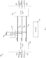
- FIG. 1 is a block diagram of an online UPS 100 according to one aspect of the present invention.
- the UPS 100 includes a first input phase line 102a, a second input phase line 102b, a third input phase line 102c, a PFC rectifier 104, a positive DC-bus 106, a mid-point bus 108, a negative DC-bus 110, an inverter 112, a first output phase line 114a, a second output phase line 114b, a third output phase line 114c, and a controller 116.
- the UPS 100 also includes a battery 118 and a battery interface 120.
- the inverter 112 is a three level inverter.
- the inverter 112 is configured based on an NPC (Neutral Point Clamped) -2 topology.
- NPC Neutral Point Clamped
- the inverter 112 is configured based on another appropriate 3-level inverter topology (e.g., NPC-1 topology).
- Each input phase lines 102a-c is configured to be coupled to one phase of a three phase power source and is coupled to the PFC rectifier 104.
- the PFC rectifier 104 is coupled to the inverter 112 via the positive DC bus 106, the mid-point bus 108, and the negative DC-bus 110.
- the inverter 112 is also configured to be coupled to a load via at least one of the first output phase line 114a, the second output phase line 114b, and the third output phase line 114c.
- the battery 118 is also coupled to the positive DC bus 106, the mid-point DC bus 108, and the negative DC-bus 110 via the battery interface 120.
- the battery interface 120 is a bidirectional DC-DC converter.
- the controller 116 is coupled to the PFC rectifier 104, the battery interface 120, and the inverter 112 and is configured to provide control signals to the PFC rectifier 104, the battery interface 120, and the inverter 112.
- the controller 116 monitors the input AC power received by the input phase lines 102a-c and is configured to operate the UPS 100 in different modes of operation based on the status of the input AC power received by the input phase lines 102a-c.
- the controller 116 operates the UPS 100 in a normal mode of operation.
- AC power from the input phase lines 102a-c is provided to the PFC rectifier 104.
- the controller 116 operates the PFC rectifier 104 to convert the input AC power into DC power and provide the converted DC power to the positive DC bus 106 and the negative DC bus 110.
- the controller 116 also operates the PFC rectifier 104 to provide PFC at the input phase lines 102a-c.
- the inverter 112 receives DC power from the positive and negative DC busses 106, 110 and operates over high-frequency switching cycles to convert the DC power into regulated AC power, and provides the regulated AC power to a load coupled to at least one of the output phase lines 114a-c.
- DC power may also be provided from the positive and negative DC busses 106, 110 to the battery interface 120 and the controller 116 operates the battery interface 120 to convert the DC power from the DC busses 106, 110 into DC power at a desired level.
- the DC power from the battery interface 120 is provided to the battery 118 to charge the battery.
- the controller 116 When AC power provided to the input phase lines 102a-c is not acceptable (i.e., below an input power threshold), the controller 116 operates the UPS 100 in a backup mode of operation.
- DC power from the battery 118 is regulated by the battery interface 120 and provided to the positive and negative DC busses106, 110.
- the inverter 112 receives the DC power from the DC busses 106, 110 and operates over high-frequency switching cycles to convert the DC power into regulated AC power, and provides the regulated AC power to a load coupled to at least one of the output phase lines 114a-c.
- the controller 116 In both the normal and backup modes of operation, while operating the inverter 112 over high-frequency switching cycles to convert the DC power from the DC busses 106, 110 into regulated AC power to provide to the load, the controller 116 also operates the inverter 112 to balance the voltages on the positive and negative DC busses 106, 108.
- the controller 116 operates the 3-level inverter 112 to operate at least partially as a 2-level inverter during one half-period of an AC line cycle, thus delivering energy to the opposite DC-bus during the time it is operated as a 2-level inverter. Operation of the inverter 112 is discussed in greater detail below.
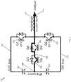
- FIGS. 2-4 are more detailed schematic diagrams illustrating operation of the inverter 112 during a positive half-period of an AC line cycle (i.e., 50Hz/60Hz).
- the inverter 112 includes a plurality of switches including a first switch (Q1) 202, a second switch (Q2) 204, a third switch (Q3) 206, and a fourth switch (Q4) 208.
- the inverter 112 also includes an output inductor 210 and an output 212.
- each of the plurality of switches 202, 204, 206, 208 is an Insulated Gate Bipolar Transistor (IGBT); however, in other embodiments, each switch 202, 204, 206, 208 can be another appropriate type of switch and/or transistor (e.g., a Metal-Oxide-Semiconductor Field-Effect Transistor (MOSFET)).
- each switch 202, 204, 206, 208 includes a diode connected in antiparallel to the switch. In at least on embodiment, the diode is the intrinsic body-diode of a MOSFET or a co-pack diode of an IGBT.
- the drain of the first switch (Q1) 202 is coupled to the positive DC-bus 106 and the emitter of the first switch (Q1) 202 is coupled to a first end of the inductor 210.
- the drain of the second switch (Q2) 204 is coupled to the first end of the inductor 210 and the emitter of the second switch (Q2) 204 is coupled to the negative DC-bus 110.
- the drain of the third switch (Q3) 206 is coupled to the mid-point bus 108 and the emitter of the third switch (Q3) 206 is coupled to the emitter of the fourth switch (Q4) 208.
- the drain of the fourth switch (Q4) 208 is coupled to the first end of the inductor 210.
- the second end of the inductor 210 is coupled to the output 212.
- the mid-point bus 108 is coupled to the positive DC bus 106 via a first capacitor 201 and is coupled to the negative DC bus 110 via a second capacitor 203.
- the controller 116 is coupled to the gate of each switch 202, 204, 206, 208 and is configured to provide control signals to the gate of each switch 202, 204, 206, 208.
- FIG. 2 illustrates a first mode of operation of the inverter 112 during a high-frequency switching cycle in the positive half-period of a line cycle where the output current of the inverter (i.e., the current through the output 212) is boosted.
- the controller 116 operates the first switch (Q1) 202 to close, the second switch (Q2) 204 to open, the third switch (Q3) 206 to close, and the fourth switch (Q4) to open.
- a first current path 200 is formed including the mid-point bus 108, the first capacitor 201, the positive DC bus 106, the first switch (Q1) 202, the inductor 210, and the output 212.
- the first current path 200 draws energy from the positive DC bus 106 and boosts current through the output 212.
- FIG. 3 illustrates a second mode of operation of the inverter 112 during a high-frequency switching cycle in the positive half-period of the line cycle where current is free-wheeling in the mid-point DC bus 108.
- the controller 116 operates the first switch (Q1) 202 to open, the second switch (Q2) 204 to open, the third switch (Q3) 206 to close, and the fourth switch (Q4) to close.
- a second current path 300 is formed including the mid-point bus 108, the third switch (Q3) 206, the fourth switch (Q4) 208, the inductor 210, and the output 212.
- current free-wheels through the inverter 112 via the second current path 300.
- FIG. 4 illustrates a third mode of operation of the inverter 112 during a high-frequency switching cycle in the positive half-period of the line cycle where current is free-wheeling in the negative DC bus 110.
- the controller 116 operates the first switch (Q1) 202 to open, the second switch (Q2) to close, the third switch (Q3) 206 to open, and the fourth switch (Q4) to open.
- a third current path 400 is formed including the mid-point bus 108, the second capacitor 203, the negative DC bus 110, a diode of the second switch (Q2) 204, the inductor 210, and the output 212.
- the inverter is operating in the positive half-period and the output current is positive (i.e., inverter operating in the 1 st quadrant)
- current free-wheels through the inverter 112 via the third current path 400 and the third current path 400 delivers energy to the negative DC bus 110.
- the controller 116 By operating the inverter 112 in the first, second, and/or third modes during the positive half-period, the controller 116 operates the inverter 112 to not only provide desired output power to the output 212 but also to balance the voltages on positive and negative DC busses 106, 110. For example, the controller 116 monitors the output power of the inverter 112 and operates the inverter 112 in the first mode of operation to regulate the power (derived from the positive DC bus 106) provided to the output lines 114a-c.
- the controller 116 also monitors a voltage level of the positive DC bus 106 and a voltage level of the negative DC bus 110 and operates the inverter 112 to alternate between the second and third modes of operation to balance the voltage level of the positive DC bus 106 with the voltage level of the negative DC bus 110.
- the controller 116 monitors the voltage level of the positive DC bus 106 and the voltage level of the negative DC bus 110 and determines whether the voltages on the positive DC bus 106 and the negative DC bus 110 are unbalanced. In response to determining that the voltages on the positive DC bus 106 and the negative DC bus 110 are balanced, the controller 116 operates the inverter 112 in the second mode of operation.
- the controller 116 operates the inverter 112 partially in the third mode of operation during the positive half-period to transfer energy from the positive DC bus 106 to the negative DC bus 110 (i.e., to balance the voltage on the negative DC bus 110 with the voltage on the positive DC bus 106).
- Alternating between the second mode of operation and the third mode of operation is done by turning on or off the mid-point switches (i.e., the third switch (Q3) 206 and the fourth switch (Q4) 208). More specifically, if no energy transfer is required between the positive DC bus 106 and the negative DC bus 110, the controller 116 operates the inverter 112 in the second mode of operation such that current free-wheels through the mid-point DC bus 108. If energy transfer between the positive DC bus 106 and the negative DC bus 110 is required, the controller 116 operates the inverter 112 in the third mode of operation such that current free wheels through the negative DC bus 110 and the diode of the second switch (Q2) 204 for at least a part of the positive half-period.
- the mid-point switches i.e., the third switch (Q3) 206 and the fourth switch (Q4) 208.
- the controller 116 operates the inverter 112 as a 3-level inverter to draw power to the output from the negative DC bus 110 only via the second switch (Q2) (similar to the first mode of operation) or the mid-point switches (i.e., the third switch (Q3) 206 and the fourth switch (Q4) 208).
- the controller 116 can also operate the inverter 112 in different modes of operation during the negative half-period of an AC line cycle to not only provide desired output power to the output 212 but also to balance the voltages on positive and negative DC busses 106, 110. For example, during the negative half-period, the controller 116 can operate the inverter 112 to draw energy from the negative DC bus 110 to boost output current of the inverter 112 (e.g., similar to the first mode of operation described above).
- the controller can also operate the inverter 112 such that current free-wheels in the mid-point DC bus 108 when the transfer of energy from the negative DC bus 110 to the positive DC bus 106 is not required (e.g., similar to the second mode of operation described above), and, assuming that the inverter is operating in the negative half-period and the output current is negative (i.e., inverter operating in the 3 rd quadrant), such that current free-wheels in the positive DC bus 106 to deliver energy to the positive DC bus 106 when the transfer of energy from the negative DC bus 110 to the positive DC bus 106 is required to balance the voltages on the positive and negative DC busses 106, 110.
- the controller 116 can balance the voltages between the positive and negative DC busses 106, 110.
- 2-level operation e.g., the third mode of operation described above
- 3-level operation e.g., the second mode of operation described above
- the controller 116 can balance the voltages between the positive and negative DC busses 106, 110.
- FIG. 5 is a graph 500 illustrating a control scheme of the inverter 112 according to at least one embodiment.
- the graph 500 includes a first trace 502 illustrating an output AC voltage waveform (VAC) of the inverter 112, and a second trace 504 illustrating a high frequency (e.g., 20 kHz) Pulse Width Modulation (PWM) voltage of the inverter 112.
- VAC output AC voltage waveform
- PWM Pulse Width Modulation
- the controller 116 operates the inverter 112 to operate as purely a 2-level converter in only a portion (e.g., from 3ms to 7ms) of each positive half-period (e.g., 50 Hz half period).
- current free-wheels through the negative DC bus 110 to transfer energy from the positive DC bus 106 to the negative DC bus 110 and thus balance the voltage on the positive DC bus 106 and the negative DC bus 110.
- Operation of the inverter 112 per the control scheme illustrated in FIG. 5 may exhibit several benefits. For example, as the 2-level operation of the inverter 112 is distributed evenly in each half-period, the regulation speed/bandwidth will be relatively high. In addition, if the 2-level operation is centered around the top-point of a half period of the corresponding output waveform 502 (e.g., at 5ms shown in FIG. 5 ), the inductor ripple current may be almost unaffected. For example, as shown in FIG. 6 (including a graph 600 illustrating operation of the inverter112 in 2-level and 3-level operation), inductor ripple current for 3-level operation 604 is almost identical to the inductor ripple current for 2-level operation 602 in the shaded areas 606. As such, if the 2-level operation is centered around the top-point of a half period, core losses and output ripple will substantially not be affected.
- FIG. 7 includes a graph 700 illustrating operation of the inverter 112 in 2-level and 3-level operation.
- shifting between 2-level and 3-level operation when the 2-level operation is centered around the top-point of a half period, has relatively little impact on the duty cycle of the inverter 112.
- the inverter duty cycles during 2-level operation and 3-level operation are almost identical around the line-cycle top point.
- the inverter regulation loop may not be required to drastically alter the duty cycle when the inverter is switched between 2-level and 3-level operation.
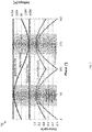
- FIG. 8 is a graph 800 illustrating another control scheme of the inverter 112 according to at least one embodiment.
- the graph 800 includes a first trace 802 illustrating an output AC voltage waveform (VAC) of the inverter 112, and a second trace 804 illustrating a high-frequency PWM voltage of the inverter 112.
- VAC output AC voltage waveform
- the controller 116 operates the inverter 112 to operate as partly in 3-level and 2-level operation during each high-frequency PWM switching cycle 804 in one half period.
- the inverter 112 operates as a combined 2-level/3-level inverter in the positive half-period from 0ms to 10ms.
- the control scheme illustrated in FIG. 8 may have several drawbacks as compared to the control scheme discussed above with respect to FIG. 5 .
- the control scheme illustrated in FIG. 8 may result in increased switching losses as the inverter PWM voltage has to shift level twice as many times, even if only a small amount of energy transfer is needed.
- ripple current (and hence, core losses) in the inverter 112 may increase noticeably as more energy is transferred between busses.
- the inverter 112 is operated purely as a 2-level inverter for an entire half period (e.g., 50Hz half period) of an AC line cycle. For example, if only a small amount of energy has to be transferred between the DC busses 106, 110 to balance the busses, one out of every 100 half-cycles can be operated with 2-level operation and the remaining ninety-nine cycles out of every 100 half-cycles would be operated in 3-level operation. If more power needs to be transferred, the inverter 112 can be operated in 2-level operation more often. When compared to the control scheme of FIG. 8 , this method considerably reduces switching losses as 2-level operation is typically only implemented in a small fraction of half-periods. However, in the limited number of 2-level half periods, the inductor ripple current can become very high, especially around an output voltage of 0V. This may impact ripple on the output 114a-c and may even affect inverter stability.
- an entire half period e.g., 50Hz half period
- the inverter 112 by operating the inverter 112 as purely as a 2-level inverter for a limited number of half periods, it may be difficult to make a successful level shift between the 2-level and the 3-level operation, as the shift has to be made close to the line-cycle zero-crossing, voltage is typically tracked poorly in 3-level operation, and the inverter 112 might be operating in Discontinuous Conduction Mode (DCM).
- DCM Discontinuous Conduction Mode
- the regulation speed/bandwidth will be very low (e.g., ⁇ 1Hz).
- the duty cycle of the inverter 112 must be carefully controlled to maintain a smooth transition. For example, if the inverter 112 is operated (in 2-level operation) to transfer energy from the positive DC bus 106 to the negative DC bus 110 such that current free wheels through the negative DC bus 110 and the diode of the second switch (Q2) 204 for at least a part of a positive half-period (e.g., as shown in the third mode of operation of FIG. 4 ), when the inverter 112 is operated in 3-level operation (e.g., as shown in the first mode of operation of FIG. 2 ), the duty cycle of the first switch Q1 (202) must be increased to account for the reduction in output current due to the 2-level operation.
- the inverter 112 duty cycle can be stepped up to compensate for the shift between 2-level and 3-level operation.
- Duty cycle calculation for 3-level vs. 2-level operation (assuming the same voltage on the positive DC bus 106 and the negative DC bus 110) is discussed below.
- the resulting expression for the 2-level duty cycle (D 2level ) is a relatively simple expression that is a function of the 3-level duty cycle (D 3level ).
- the resulting expression is important for a smooth transition during a level shift as it can be used to "step" the inverter duty cycle instantaneously at the moment when a level shift is requested.
- the controller 116 can simply adjust the duty cycle of the inverter 112 based on the above expression, and vice versa. By operating based on the expression above, the inverter regulation loop may not notice any change due to level shift.
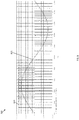
- FIG. 9 includes a graph 900 representing the average power transferred during one full 50Hz line cycle vs. the time the inverter 112 is operated as a 2-level inverter.
- the graph 900 includes a first trace 902 representing average power transferred for a 10kW inverter load, a second trace 904 representing average power transferred to a 5kW inverter load vs.
- a third trace 906 representing average power transferred to a 2kW inverter load vs. the 2-level operation time
- a fourth trace 908 representing average power transferred to a 1kW inverter load vs. the 2-level operation time
- a fifth trace 910 representing average power transferred to a 100W inverter load vs. the 2-level operation time.
- FIG. 10 illustrates an example block diagram of computing components forming a system 1000 which may be configured to implement one or more aspects disclosed herein.
- the system 1000 may be communicatively coupled to the controller 116 or included within the controller 116.
- the system 1000 may also be configured to operate a UPS as discussed above.
- the system 1000 may include for example a computing platform such as those based on Intel PENTIUM-type processor, Motorola PowerPC, Sun UltraSPARC, Texas Instruments-DSP, Hewlett-Packard PA-RISC processors, or any other type of processor.
- System 1000 may include specially-programmed, special-purpose hardware, for example, an application-specific integrated circuit (ASIC).
- ASIC application-specific integrated circuit
- Various aspects of the present disclosure may be implemented as specialized software executing on the system 1000 such as that shown in FIG. 10 .
- the system 1000 may include a processor/ASIC 1006 connected to one or more memory devices 1010, such as a disk drive, memory, flash memory or other device for storing data. Memory 1010 may be used for storing programs and data during operation of the system 1000.
- Components of the computer system 1000 may be coupled by an interconnection mechanism 1008, which may include one or more buses (e.g., between components that are integrated within a same machine) and/or a network (e.g., between components that reside on separate machines).
- the interconnection mechanism 1008 enables communications (e.g., data, instructions) to be exchanged between components of the system 1000.
- the system 1000 also includes one or more input devices 1004, which may include for example, a keyboard or a touch screen.
- the system 1000 includes one or more output devices 1002, which may include for example a display.
- the computer system 1000 may contain one or more interfaces (not shown) that may connect the computer system 1000 to a communication network, in addition or as an alternative to the interconnection mechanism 1008.
- the system 1000 may include a storage system 1012, which may include a computer readable and/or writeable nonvolatile medium in which signals may be stored to provide a program to be executed by the processor or to provide information stored on or in the medium to be processed by the program.
- the medium may, for example, be a disk or flash memory and in some examples may include RAM or other non-volatile memory such as EEPROM.
- the processor may cause data to be read from the nonvolatile medium into another memory 1010 that allows for faster access to the information by the processor/ASIC than does the medium.
- This memory 1010 may be a volatile, random access memory such as a dynamic random access memory (DRAM) or static memory (SRAM). It may be located in storage system 1012 or in memory system 1010.
- DRAM dynamic random access memory
- SRAM static memory
- the processor 1006 may manipulate the data within the integrated circuit memory 1010 and then copy the data to the storage 1012 after processing is completed.
- a variety of mechanisms are known for managing data movement between storage 1012 and the integrated circuit memory element 1010, and the disclosure is not limited thereto. The disclosure is not limited to a particular memory system 1010 or a storage system 1012.
- the system 1000 may include a computer platform that is programmable using a high-level computer programming language.
- the system 1000 may be also implemented using specially programmed, special purpose hardware, e.g. an ASIC.
- the system 1000 may include a processor 1006, which may be a commercially available processor such as the well-known Pentium class processor available from the Intel Corporation. Many other processors are available.
- the processor 1006 may execute an operating system which may be, for example, a Windows operating system available from the Microsoft Corporation, MAC OS System X available from Apple Computer, the Solaris Operating System available from Sun Microsystems, or UNIX and/or LINUX available from various sources. Many other operating systems may be used.
- the processor and operating system together may form a computer platform for which application programs in high-level programming languages may be written. It should be understood that the disclosure is not limited to a particular computer system platform, processor, operating system, or network. Also, it should be apparent to those skilled in the art that the present disclosure is not limited to a specific programming language or computer system. Further, it should be appreciated that other appropriate programming languages and other appropriate computer systems could also be used.
- the level shift inverter operation approach is utilized with an NPC-2 topology; however, in other embodiments, the approach can be utilized with other 3-level topologies such as the NPC-1 topology.
- the approach may also be utilized in some bi-directional PFC front end converters.
- the bi-directional PFC front end converter can similarly be configured to operate in a 2-level mode of operation during at least a part of a high-frequency inverter switching cycle in one half-period of an AC line cycle to transfer energy between DC busses.
- the level shift inverter operation is utilized with a UPS coupled to a three-phase power source; however, in other embodiments, the level shift inverter operation may be utilized in a UPS coupled to another type of power (e.g., single phase or split-phase power).
- the level shift inverter operation is utilized with a UPS that received AC power from an AC power source; however, in other embodiments, the level shift inverter operation described above is utilized with a UPS that receives DC power from a DC power source.
- a UPS system that utilizes its inverter as a DC bus balancer, thus saving the additional cost and footprint typically required by a dedicated bus balancer circuit.
- the UPS system operates by controlling the 3-level inverter to operate as a 2-level inverter during at least a part of a high-frequency inverter switching cycle in one half-period of an AC line cycle.
Landscapes
- Engineering & Computer Science (AREA)
- Power Engineering (AREA)
- Business, Economics & Management (AREA)
- Emergency Management (AREA)
- Inverter Devices (AREA)
Claims (15)
- Un système d'alimentation sans interruption (ASI) (100), le système ASI (100) comprenant :une entrée configurée pour être couplée à une source de CA et pour recevoir de la puissance en CA d'entrée en provenance de la source de CA ;une sortie configurée pour fournir de la puissance en CA de sortie à une charge ;un convertisseur couplé à l'entrée et configuré pour convertir la puissance d'entrée en puissance en CC ayant un niveau de tension en CC positif et un niveau de tension en CC négatif ;une pluralité de bus de CC (106, 108, 110) couplés au convertisseur et configurés pour recevoir la puissance en CC en provenance du convertisseur, la pluralité de bus de CC (106, 108, 110) incluant un bus de CC positif (106) configuré pour maintenir le niveau de tension en CC positif, un bus de CC de point milieu (108), et un bus de CC négatif (110) configuré pour maintenir le niveau de tension en CC négatif ;un onduleur à 3 niveaux (112) couplé à la pluralité de bus de CC (106, 108, 110) et configuré pour convertir la puissance en CC provenant de la pluralité de bus de CC (106, 108, 110) en la puissance en CA de sortie et fournir la puissance en CA de sortie à la sortie ; etun appareil de commande (116) configuré pour surveiller le niveau de tension en CC positif et le niveau de tension en CC négatif, identifier un déséquilibre entre le niveau de tension en CC positif et le niveau de tension en CC négatif, et commander sélectivement, sur la base du déséquilibre, l'onduleur à 3 niveaux (112) pour qu'il fonctionne dans un mode de fonctionnement à 2 niveaux et un mode de fonctionnement à 3 niveaux afin de transférer de l'énergie entre le bus de CC positif (106) et le bus de CC négatif (110),dans lequel dans le fait de faire fonctionner l'onduleur à 3 niveaux (112) dans le mode de fonctionnement à 2 niveaux, l'appareil de commande (116) est configuré en outre pour faire fonctionner l'onduleur à 3 niveaux (112) pour qu'il couple en alternance la sortie au bus de CC positif (106) et au bus de CC négatif (110) afin de fournir en alternance une impulsion de CC positif et une impulsion de CC négatif, respectivement, à la sortie,dans lequel dans le fait de faire fonctionner l'onduleur à 3 niveaux (112) dans le mode de fonctionnement à 3 niveaux, l'appareil de commande (116) est configuré en outre pour faire fonctionner l'onduleur à 3 niveaux (112) pour qu'il couple en alternance la sortie au bus de CC de point milieu (108) et à un bus parmi le bus de CC positif (106) et le bus de CC négatif (110), etdans lequel dans le fait de commander sélectivement l'onduleur à 3 niveaux (112) pour qu'il fonctionne dans le mode de fonctionnement à 2 niveaux et le mode de fonctionnement à 3 niveaux, l'appareil de commande (116) est configuré en outre pour faire fonctionner l'onduleur à 3 niveaux (112), durant une demi-période d'un cycle de ligne, dans le mode de fonctionnement à 2 niveaux afin de transférer de l'énergie entre le bus de CC positif (106) et le bus de CC négatif (110).
- Le système ASI (100) de la revendication 1, dans lequel dans le fait de commander sélectivement l'onduleur à 3 niveaux (112) pour qu'il fonctionne dans le mode de fonctionnement à 2 niveaux et le mode de fonctionnement à 3 niveaux, l'appareil de commande (116) est configuré en outre pour faire fonctionner l'onduleur à 3 niveaux (112), durant une demi-période positive d'un cycle de ligne, dans le mode de fonctionnement à 2 niveaux afin de transférer de l'énergie du bus de CC positif (106) au bus de CC négatif (110).
- Le système ASI (100) de la revendication 2, dans lequel dans le fait de faire fonctionner l'onduleur à 3 niveaux (112), durant la demi-période positive du cycle de ligne, dans le mode de fonctionnement à 2 niveaux afin de transférer de l'énergie du bus de CC positif (106) au bus de CC négatif (110), l'appareil de commande (116) est configuré en outre pour faire fonctionner l'onduleur à 3 niveaux (112) dans le mode de fonctionnement à 2 niveaux pendant une portion de la demi-période positive.
- Le système ASI (100) de la revendication 2, dans lequel dans le fait de faire fonctionner l'onduleur à 3 niveaux (112), durant la demi-période positive du cycle de ligne, dans le mode de fonctionnement à 2 niveaux afin de transférer de l'énergie du bus de CC positif (106) au bus de CC négatif (110), l'appareil de commande (116) est configuré en outre pour faire fonctionner l'onduleur à 3 niveaux (112) pour qu'il alterne entre le mode de fonctionnement à 2 niveaux et le mode de fonctionnement à 3 niveaux durant la demi-période positive.
- Le système ASI (100) de la revendication 2, dans lequel dans le fait de faire fonctionner l'onduleur à 3 niveaux (112), durant la demi-période positive du cycle de ligne, dans le mode de fonctionnement à 2 niveaux afin de transférer de l'énergie du bus de CC positif (106) au bus de CC négatif (110), l'appareil de commande (116) est configuré en outre pour faire fonctionner l'onduleur à 3 niveaux (112) dans le mode de fonctionnement à 2 niveaux pendant toute la demi-période positive.
- Le système ASI (100) de la revendication 2, dans lequel dans le fait de commander sélectivement l'onduleur à 3 niveaux (112) pour qu'il fonctionne dans le mode de fonctionnement à 2 niveaux et le mode de fonctionnement à 3 niveaux, l'appareil de commande (116) est configuré en outre pour faire fonctionner l'onduleur à 3 niveaux (112), durant une demi-période négative du cycle de ligne, dans le mode de fonctionnement à 2 niveaux afin de transférer de l'énergie du bus de CC négatif (110) au bus de CC positif (106).
- Le système ASI (100) de la revendication 1, dans lequel l'onduleur à 3 niveaux comprend une pluralité d'interrupteurs (202, 204, 206, 208) couplés entre la pluralité de bus de CC (106, 108, 110), et
dans lequel dans le fait de commander sélectivement l'onduleur à 3 niveaux (112) pour qu'il fonctionne dans le mode de fonctionnement à 2 niveaux et le mode de fonctionnement à 3 niveaux, l'appareil de commande (116) est configuré en outre pour commander la pluralité d'interrupteurs (202, 204, 206, 208) pour :qu'ils fonctionnent, dans un premier mode de fonctionnement, afin de générer un premier chemin de courant qui prélève de l'énergie du bus de CC positif (106) et augmente le courant passant par la sortie ;qu'ils fonctionnent, dans un deuxième mode de fonctionnement, afin de générer un deuxième chemin de courant entre le bus de CC de point milieu (108) et la sortie ; etqu'ils fonctionnent, dans un troisième mode de fonctionnement, afin de générer un troisième chemin de courant qui délivre de l'énergie au bus de CC négatif (110). - Le système ASI (100) de la revendication 7, dans lequel la pluralité d'interrupteurs (202, 204, 206, 208) inclut :un premier interrupteur (202) couplé entre le bus de CC positif (106) et la sortie ;un deuxième interrupteur (204) couplé entre le bus de CC négatif (110) et la sortie ;un troisième interrupteur (206) couplé au bus de CC de point milieu ; etun quatrième interrupteur (208) couplé entre le troisième interrupteur (206) et la sortie.
- Le système ASI (100) de la revendication 8, dans lequel dans le fait de faire fonctionner la pluralité d'interrupteurs (202, 204, 206, 208) dans le premier mode de fonctionnement, l'appareil de commande (116) est configuré en outre pour commander le premier interrupteur (202) pour qu'il se ferme afin de coupler le bus de CC positif (106) à la sortie par l'intermédiaire du premier interrupteur (202).
- Le système ASI (100) de la revendication 9, dans lequel dans le fait de faire fonctionner la pluralité d'interrupteurs (202, 204, 206, 208) dans le deuxième mode de fonctionnement, l'appareil de commande (116) est configuré en outre pour commander le troisième interrupteur (206) et le quatrième interrupteur (208) pour qu'ils se ferment afin de coupler le bus de CC de point milieu (108) à la sortie par l'intermédiaire du troisième interrupteur (206) et du quatrième interrupteur (208).
- Le système ASI (100) de la revendication 10, dans lequel dans le fait de faire fonctionner la pluralité d'interrupteurs (202, 204, 206, 208) dans le troisième mode de fonctionnement, l'appareil de commande (116) est configuré en outre pour commander le deuxième interrupteur (204) afin de coupler le bus de CC négatif (110) à la sortie par l'intermédiaire du deuxième interrupteur (204).
- Le système ASI (100) de la revendication 1, dans lequel le convertisseur est configuré en outre pour recevoir de la puissance en CA d'entrée triphasée en provenance de la source de CA et convertir la puissance en CA d'entrée triphasée en la puissance en CC, et
dans lequel l'onduleur à 3 niveaux (112) est configuré en outre pour convertir la puissance en CC provenant de la pluralité de bus de CC (106, 108, 110) en puissance en CA de sortie triphasée et fournir la puissance en CA triphasée à la sortie. - Un procédé pour faire fonctionner une alimentation sans interruption (ASI) (100) comprenant une entrée configurée pour être couplée à une source de puissance, une sortie, une pluralité de bus de CC (106, 108, 110) incluant un bus de CC positif (106), un bus de CC de point milieu (108), et un bus de CC négatif (110), et un onduleur à 3 niveaux (112) couplé à la pluralité de bus de CC (106, 108, 110), le procédé comprenant :le fait de recevoir de la puissance d'entrée en provenance de la source de puissance ;le fait de maintenir un niveau de tension en CC positif sur le bus de CC positif (106) ;le fait de maintenir un niveau de tension en CC négatif sur le bus de CC négatif (110) ;le fait de convertir, avec l'onduleur à 3 niveaux (112), la puissance en CC provenant de la pluralité de bus de CC (106, 108, 110) en puissance en CA de sortie ;le fait de fournir la puissance en CA de sortie à la sortie ;le fait de surveiller le niveau de tension en CC positif et le niveau de tension en CC négatif ;le fait d'identifier un déséquilibre entre le niveau de tension en CC positif et le niveau de tension en CC négatif ; etle fait de commander sélectivement, sur la base du déséquilibre, l'onduleur à 3 niveaux (112) pour qu'il fonctionne dans un mode de fonctionnement à 2 niveaux et un mode de fonctionnement à 3 niveaux afin de transférer de l'énergie entre le bus de CC positif (106) et le bus de CC négatif (108),dans lequel le fait de faire fonctionner l'onduleur à 3 niveaux (112) dans le mode de fonctionnement à 2 niveaux inclut le fait de faire fonctionner l'onduleur à 3 niveaux (112) pour qu'il couple en alternance la sortie au bus de CC positif (106) et au bus de CC négatif (110) afin de fournir en alternance une impulsion de CC positif et une impulsion de CC négatif, respectivement, à la sortie,dans lequel le fait de faire fonctionner l'onduleur à 3 niveaux (112) dans le mode de fonctionnement à 3 niveaux inclut le fait de faire fonctionner l'onduleur à 3 niveaux (112) pour qu'il couple en alternance la sortie au bus de CC de point milieu (108) et à un bus parmi le bus de CC positif (106) et le bus de CC négatif (110), etdans lequel le fait de commander sélectivement l'onduleur à 3 niveaux (112) pour qu'il fonctionne dans le mode de fonctionnement à 2 niveaux et le mode de fonctionnement à 3 niveaux inclut le fait de faire fonctionner l'onduleur à 3 niveaux (112), durant une demi-période d'un cycle de ligne, dans le mode de fonctionnement à 2 niveaux afin de transférer de l'énergie entre le bus de CC positif (106) et le bus de CC négatif (110).
- Le procédé de la revendication 13, dans lequel le fait de commander sélectivement l'onduleur à 3 niveaux (112) pour qu'il fonctionne dans le mode de fonctionnement à 2 niveaux et le mode de fonctionnement à 3 niveaux inclut :le fait de faire fonctionner l'onduleur à 3 niveaux (112), durant une demi-période positive d'un cycle de ligne, dans le mode de fonctionnement à 2 niveaux afin de transférer de l'énergie du bus de CC positif (106) au bus de CC négatif (110) ; etle fait de faire fonctionner l'onduleur à 3 niveaux (112), durant une demi-période négative du cycle de ligne, dans le mode de fonctionnement à 2 niveaux afin de transférer de l'énergie du bus de CC négatif (110) au bus de CC positif (106).
- Le procédé de la revendication 14, dans lequel l'ASI (100) comprend en outre une pluralité d'interrupteurs (202, 204, 206, 208) couplés entre les bus de CC (106, 108, 110), et dans lequel le fait de faire fonctionner l'onduleur à 3 niveaux (112), durant la demi-période positive du cycle de ligne, dans le mode de fonctionnement à 2 niveaux afin de transférer de l'énergie du bus de CC positif (106) au bus de CC négatif (110) inclut :le fait de faire fonctionner, dans un premier mode de fonctionnement, la pluralité d'interrupteurs (202, 204, 206, 208) afin d'augmenter le courant de sortie de l'onduleur à 3 niveaux (112) ;le fait de faire fonctionner, dans un deuxième mode de fonctionnement, la pluralité d'interrupteurs (202, 204, 206, 208) afin de faire passer en roue-libre du courant dans le bus de CC de point milieu (108) ; etle fait de faire fonctionner, dans un troisième mode de fonctionnement, la pluralité d'interrupteurs (202, 204, 206, 208) afin de faire passer en roue-libre du courant dans le bus de CC négatif (110), transférant de l'énergie du bus de CC positif (106) au bus de CC négatif (110).
Applications Claiming Priority (1)
| Application Number | Priority Date | Filing Date | Title |
|---|---|---|---|
| US15/292,461 US10211672B2 (en) | 2016-10-13 | 2016-10-13 | DC-link bus balancer |
Publications (2)
| Publication Number | Publication Date |
|---|---|
| EP3309927A1 EP3309927A1 (fr) | 2018-04-18 |
| EP3309927B1 true EP3309927B1 (fr) | 2021-09-29 |
Family
ID=60080595
Family Applications (1)
| Application Number | Title | Priority Date | Filing Date |
|---|---|---|---|
| EP17195374.8A Active EP3309927B1 (fr) | 2016-10-13 | 2017-10-09 | Équilibreur de bus à liaison cc |
Country Status (3)
| Country | Link |
|---|---|
| US (1) | US10211672B2 (fr) |
| EP (1) | EP3309927B1 (fr) |
| CN (1) | CN107947338B (fr) |
Families Citing this family (17)
| Publication number | Priority date | Publication date | Assignee | Title |
|---|---|---|---|---|
| EP3138190B1 (fr) * | 2014-05-01 | 2022-11-16 | Schneider Electric IT Corporation | Commande d'alimentation électrique |
| GB2566479B (en) * | 2017-09-14 | 2019-10-23 | Eltek As | DC-DC Converter |
| CN110707953B (zh) * | 2018-07-10 | 2025-02-18 | 施耐德电气It公司 | 准五电平逆变器 |
| JP6955635B2 (ja) * | 2018-08-03 | 2021-10-27 | 東芝三菱電機産業システム株式会社 | 無停電電源装置 |
| US10784714B2 (en) * | 2018-11-30 | 2020-09-22 | Schneider Electric It Corporation | 3 phase UPS bus balancer |
| CN109921503B (zh) * | 2019-02-19 | 2020-08-25 | 江苏理工学院 | 车载高集成度混合电源、能量管理与控制系统及其方法 |
| EP3793077B1 (fr) * | 2019-09-12 | 2024-07-17 | ABB Schweiz AG | Alimentation sans coupure pour connexion d'une charge multiphase sur une source de courant alternatif et une source de courant continu |
| EP3820041A1 (fr) * | 2019-11-05 | 2021-05-12 | Carrier Corporation | Entraînement doté de modules d'onduleur à niveaux multiples |
| CN110880741B (zh) * | 2019-12-02 | 2022-02-18 | 阳光电源股份有限公司 | 逆变系统及其对称三电平升压电路的输入错接检测方法 |
| US10985652B1 (en) * | 2020-03-02 | 2021-04-20 | Google Llc | Power balancer for series-connected load zones of an integrated circuit |
| CN112510814A (zh) * | 2020-11-25 | 2021-03-16 | 漳州科华技术有限责任公司 | Ups供电控制方法、装置及终端设备 |
| EP4087113B1 (fr) | 2021-05-06 | 2025-07-02 | ABB Schweiz AG | Convertisseur cc/cc double boost |
| CA3236145A1 (fr) | 2021-10-22 | 2023-04-27 | Southwest Electric Co. | Transformateur de distribution triphase a equilibrage de la charge a sorties multiples |
| CN114629224B (zh) * | 2022-03-24 | 2024-10-08 | 漳州科华电气技术有限公司 | Ups系统直流母线电压的中点平衡控制方法及逆变器 |
| CN115241926B (zh) * | 2022-09-16 | 2023-02-28 | 深圳市首航新能源股份有限公司 | 母线电压控制方法、母线平衡控制方法及其系统 |
| CN116455251B (zh) * | 2023-06-14 | 2023-08-29 | 麦田能源股份有限公司 | 一种三电平变换器及其控制方法 |
| US20250015742A1 (en) * | 2023-07-06 | 2025-01-09 | GM Global Technology Operations LLC | Multi-switch module packaging for multilevel inverter |
Family Cites Families (20)
| Publication number | Priority date | Publication date | Assignee | Title |
|---|---|---|---|---|
| US5517401A (en) * | 1992-02-07 | 1996-05-14 | Fuji Electric Co., Ltd. | Three level pulse width modulated inverter for an electric vehicle |
| JP2888104B2 (ja) * | 1993-09-01 | 1999-05-10 | 株式会社日立製作所 | 電力変換装置 |
| US5910892A (en) * | 1997-10-23 | 1999-06-08 | General Electric Company | High power motor drive converter system and modulation control |
| US6842354B1 (en) * | 2003-08-08 | 2005-01-11 | Rockwell Automation Technologies, Inc. | Capacitor charge balancing technique for a three-level PWM power converter |
| US7495938B2 (en) * | 2005-04-15 | 2009-02-24 | Rockwell Automation Technologies, Inc. | DC voltage balance control for three-level NPC power converters with even-order harmonic elimination scheme |
| US8400792B2 (en) * | 2008-08-22 | 2013-03-19 | Toshiba Mitsubishi-Electric Industrial Systems Corporation | Power conversion apparatus |
| US8144490B2 (en) * | 2009-11-10 | 2012-03-27 | General Electric Company | Operation of a three level converter |
| JP2011109789A (ja) * | 2009-11-17 | 2011-06-02 | Fuji Electric Holdings Co Ltd | 電力変換装置 |
| WO2012025978A1 (fr) * | 2010-08-23 | 2012-03-01 | 東芝三菱電機産業システム株式会社 | Dispositif de conversion d'électricité |
| US8441820B2 (en) * | 2010-09-29 | 2013-05-14 | General Electric Company | DC-link voltage balancing system and method for multilevel converters |
| US8730691B2 (en) * | 2011-05-11 | 2014-05-20 | Eaton Corporation | Power conversion apparatus and methods employing variable-level inverters |
| US20130163292A1 (en) * | 2011-12-22 | 2013-06-27 | General Electric Company | Mid-point voltage control |
| US9214874B2 (en) * | 2012-07-31 | 2015-12-15 | Yashomani Y. Kolhatkar | Intelligent level transition systems and methods for transformerless uninterruptible power supply |
| CN103683356B (zh) | 2012-09-20 | 2015-10-21 | 伊顿制造(格拉斯哥)有限合伙莫尔日分支机构 | 在线式不间断电源拓扑 |
| DE102013202649A1 (de) * | 2013-02-19 | 2014-08-21 | Robert Bosch Gmbh | Wechselrichteranordnung und Ansteuerverfahren für eine Wechselrichteranordnung |
| CN104901410A (zh) | 2014-03-04 | 2015-09-09 | 伊顿公司 | 一种ups电路 |
| EP3161925B1 (fr) | 2014-06-27 | 2021-08-04 | Schneider Electric IT Corporation | Topologie d'énergie à 3 niveaux |
| US9755545B2 (en) | 2014-11-21 | 2017-09-05 | General Electric Company | System and method for unified common mode voltage injection |
| US9595876B2 (en) | 2015-02-11 | 2017-03-14 | Schneider Electric It Corporation | DC-DC converter |
| CN105305553A (zh) * | 2015-11-12 | 2016-02-03 | 广东技术师范学院 | 一种在线式不间断电源及利用该电源的电能质量治理方法 |
-
2016
- 2016-10-13 US US15/292,461 patent/US10211672B2/en active Active
-
2017
- 2017-10-09 EP EP17195374.8A patent/EP3309927B1/fr active Active
- 2017-10-12 CN CN201710948005.0A patent/CN107947338B/zh active Active
Also Published As
| Publication number | Publication date |
|---|---|
| EP3309927A1 (fr) | 2018-04-18 |
| US10211672B2 (en) | 2019-02-19 |
| CN107947338A (zh) | 2018-04-20 |
| CN107947338B (zh) | 2022-02-01 |
| US20180109136A1 (en) | 2018-04-19 |
Similar Documents
| Publication | Publication Date | Title |
|---|---|---|
| EP3309927B1 (fr) | Équilibreur de bus à liaison cc | |
| CN106253718B (zh) | Ac-dc整流器系统 | |
| EP2856598B1 (fr) | Convertisseurs de puissance bidirectionnels avec commande de tension alternative d'entrée | |
| EP3123592B1 (fr) | Convertisseur continu-continu bidirectionnel | |
| EP2807716B1 (fr) | Circuit pour transfert de puissance entre une ligne à courant continu et une ligne à courant alternatif | |
| EP3840204A2 (fr) | Convertisseur de puissance cc-cc à quatre voies de conversion de puissance | |
| US10461575B2 (en) | Multistate PWM command for 3 levels inverters | |
| US10833601B2 (en) | Multi-level inverter | |
| EP3480934B1 (fr) | Convertisseur bidirectionnel cc-ca | |
| EP3127230A1 (fr) | Système redresseur isolé et efficace | |
| US20180287504A1 (en) | Bi-directional dc-dc converter with load and source synchronized power control | |
| EP3588758A1 (fr) | Convertisseur cc-cc intégré | |
| EP3138182B1 (fr) | Commande de tension de liaison à courant continu (cc) | |
| EP3661011B1 (fr) | Équilibreur de bus d'alimentation sans coupure triphasée | |
| JP2000069763A (ja) | 電鉄用電力供給装置 | |
| Mellincovsky et al. | Transient response enhancement of PFC front end | |
| WO2015198057A1 (fr) | Commande de puissance | |
| HK1208566B (zh) | 输入ac电压控制双向功率转换器 |
Legal Events
| Date | Code | Title | Description |
|---|---|---|---|
| PUAI | Public reference made under article 153(3) epc to a published international application that has entered the european phase |
Free format text: ORIGINAL CODE: 0009012 |
|
| STAA | Information on the status of an ep patent application or granted ep patent |
Free format text: STATUS: REQUEST FOR EXAMINATION WAS MADE |
|
| 17P | Request for examination filed |
Effective date: 20171009 |
|
| AK | Designated contracting states |
Kind code of ref document: A1 Designated state(s): AL AT BE BG CH CY CZ DE DK EE ES FI FR GB GR HR HU IE IS IT LI LT LU LV MC MK MT NL NO PL PT RO RS SE SI SK SM TR |
|
| AX | Request for extension of the european patent |
Extension state: BA ME |
|
| RBV | Designated contracting states (corrected) |
Designated state(s): AL AT BE BG CH CY CZ DE DK EE ES FI FR GB GR HR HU IE IS IT LI LT LU LV MC MK MT NL NO PL PT RO RS SE SI SK SM TR |
|
| STAA | Information on the status of an ep patent application or granted ep patent |
Free format text: STATUS: EXAMINATION IS IN PROGRESS |
|
| 17Q | First examination report despatched |
Effective date: 20200715 |
|
| GRAP | Despatch of communication of intention to grant a patent |
Free format text: ORIGINAL CODE: EPIDOSNIGR1 |
|
| STAA | Information on the status of an ep patent application or granted ep patent |
Free format text: STATUS: GRANT OF PATENT IS INTENDED |
|
| INTG | Intention to grant announced |
Effective date: 20210330 |
|
| GRAS | Grant fee paid |
Free format text: ORIGINAL CODE: EPIDOSNIGR3 |
|
| GRAA | (expected) grant |
Free format text: ORIGINAL CODE: 0009210 |
|
| STAA | Information on the status of an ep patent application or granted ep patent |
Free format text: STATUS: THE PATENT HAS BEEN GRANTED |
|
| AK | Designated contracting states |
Kind code of ref document: B1 Designated state(s): AL AT BE BG CH CY CZ DE DK EE ES FI FR GB GR HR HU IE IS IT LI LT LU LV MC MK MT NL NO PL PT RO RS SE SI SK SM TR |
|
| REG | Reference to a national code |
Ref country code: GB Ref legal event code: FG4D |
|
| REG | Reference to a national code |
Ref country code: DE Ref legal event code: R096 Ref document number: 602017046672 Country of ref document: DE |
|
| REG | Reference to a national code |
Ref country code: CH Ref legal event code: EP Ref country code: AT Ref legal event code: REF Ref document number: 1435065 Country of ref document: AT Kind code of ref document: T Effective date: 20211015 |
|
| REG | Reference to a national code |
Ref country code: IE Ref legal event code: FG4D |
|
| REG | Reference to a national code |
Ref country code: LT Ref legal event code: MG9D |
|
| PG25 | Lapsed in a contracting state [announced via postgrant information from national office to epo] |
Ref country code: FI Free format text: LAPSE BECAUSE OF FAILURE TO SUBMIT A TRANSLATION OF THE DESCRIPTION OR TO PAY THE FEE WITHIN THE PRESCRIBED TIME-LIMIT Effective date: 20210929 Ref country code: NO Free format text: LAPSE BECAUSE OF FAILURE TO SUBMIT A TRANSLATION OF THE DESCRIPTION OR TO PAY THE FEE WITHIN THE PRESCRIBED TIME-LIMIT Effective date: 20211229 Ref country code: LT Free format text: LAPSE BECAUSE OF FAILURE TO SUBMIT A TRANSLATION OF THE DESCRIPTION OR TO PAY THE FEE WITHIN THE PRESCRIBED TIME-LIMIT Effective date: 20210929 Ref country code: BG Free format text: LAPSE BECAUSE OF FAILURE TO SUBMIT A TRANSLATION OF THE DESCRIPTION OR TO PAY THE FEE WITHIN THE PRESCRIBED TIME-LIMIT Effective date: 20211229 Ref country code: HR Free format text: LAPSE BECAUSE OF FAILURE TO SUBMIT A TRANSLATION OF THE DESCRIPTION OR TO PAY THE FEE WITHIN THE PRESCRIBED TIME-LIMIT Effective date: 20210929 Ref country code: SE Free format text: LAPSE BECAUSE OF FAILURE TO SUBMIT A TRANSLATION OF THE DESCRIPTION OR TO PAY THE FEE WITHIN THE PRESCRIBED TIME-LIMIT Effective date: 20210929 Ref country code: RS Free format text: LAPSE BECAUSE OF FAILURE TO SUBMIT A TRANSLATION OF THE DESCRIPTION OR TO PAY THE FEE WITHIN THE PRESCRIBED TIME-LIMIT Effective date: 20210929 |
|
| REG | Reference to a national code |
Ref country code: NL Ref legal event code: MP Effective date: 20210929 |
|
| REG | Reference to a national code |
Ref country code: AT Ref legal event code: MK05 Ref document number: 1435065 Country of ref document: AT Kind code of ref document: T Effective date: 20210929 |
|
| PG25 | Lapsed in a contracting state [announced via postgrant information from national office to epo] |
Ref country code: LV Free format text: LAPSE BECAUSE OF FAILURE TO SUBMIT A TRANSLATION OF THE DESCRIPTION OR TO PAY THE FEE WITHIN THE PRESCRIBED TIME-LIMIT Effective date: 20210929 Ref country code: GR Free format text: LAPSE BECAUSE OF FAILURE TO SUBMIT A TRANSLATION OF THE DESCRIPTION OR TO PAY THE FEE WITHIN THE PRESCRIBED TIME-LIMIT Effective date: 20211230 |
|
| PG25 | Lapsed in a contracting state [announced via postgrant information from national office to epo] |
Ref country code: AT Free format text: LAPSE BECAUSE OF FAILURE TO SUBMIT A TRANSLATION OF THE DESCRIPTION OR TO PAY THE FEE WITHIN THE PRESCRIBED TIME-LIMIT Effective date: 20210929 |
|
| REG | Reference to a national code |
Ref country code: CH Ref legal event code: PL |
|
| PG25 | Lapsed in a contracting state [announced via postgrant information from national office to epo] |
Ref country code: IS Free format text: LAPSE BECAUSE OF FAILURE TO SUBMIT A TRANSLATION OF THE DESCRIPTION OR TO PAY THE FEE WITHIN THE PRESCRIBED TIME-LIMIT Effective date: 20220129 Ref country code: SK Free format text: LAPSE BECAUSE OF FAILURE TO SUBMIT A TRANSLATION OF THE DESCRIPTION OR TO PAY THE FEE WITHIN THE PRESCRIBED TIME-LIMIT Effective date: 20210929 Ref country code: RO Free format text: LAPSE BECAUSE OF FAILURE TO SUBMIT A TRANSLATION OF THE DESCRIPTION OR TO PAY THE FEE WITHIN THE PRESCRIBED TIME-LIMIT Effective date: 20210929 Ref country code: PT Free format text: LAPSE BECAUSE OF FAILURE TO SUBMIT A TRANSLATION OF THE DESCRIPTION OR TO PAY THE FEE WITHIN THE PRESCRIBED TIME-LIMIT Effective date: 20220131 Ref country code: PL Free format text: LAPSE BECAUSE OF FAILURE TO SUBMIT A TRANSLATION OF THE DESCRIPTION OR TO PAY THE FEE WITHIN THE PRESCRIBED TIME-LIMIT Effective date: 20210929 Ref country code: NL Free format text: LAPSE BECAUSE OF FAILURE TO SUBMIT A TRANSLATION OF THE DESCRIPTION OR TO PAY THE FEE WITHIN THE PRESCRIBED TIME-LIMIT Effective date: 20210929 Ref country code: ES Free format text: LAPSE BECAUSE OF FAILURE TO SUBMIT A TRANSLATION OF THE DESCRIPTION OR TO PAY THE FEE WITHIN THE PRESCRIBED TIME-LIMIT Effective date: 20210929 Ref country code: EE Free format text: LAPSE BECAUSE OF FAILURE TO SUBMIT A TRANSLATION OF THE DESCRIPTION OR TO PAY THE FEE WITHIN THE PRESCRIBED TIME-LIMIT Effective date: 20210929 Ref country code: CZ Free format text: LAPSE BECAUSE OF FAILURE TO SUBMIT A TRANSLATION OF THE DESCRIPTION OR TO PAY THE FEE WITHIN THE PRESCRIBED TIME-LIMIT Effective date: 20210929 Ref country code: AL Free format text: LAPSE BECAUSE OF FAILURE TO SUBMIT A TRANSLATION OF THE DESCRIPTION OR TO PAY THE FEE WITHIN THE PRESCRIBED TIME-LIMIT Effective date: 20210929 |
|
| REG | Reference to a national code |
Ref country code: BE Ref legal event code: MM Effective date: 20211031 |
|
| PG25 | Lapsed in a contracting state [announced via postgrant information from national office to epo] |
Ref country code: MC Free format text: LAPSE BECAUSE OF FAILURE TO SUBMIT A TRANSLATION OF THE DESCRIPTION OR TO PAY THE FEE WITHIN THE PRESCRIBED TIME-LIMIT Effective date: 20210929 |
|
| REG | Reference to a national code |
Ref country code: DE Ref legal event code: R097 Ref document number: 602017046672 Country of ref document: DE |
|
| PG25 | Lapsed in a contracting state [announced via postgrant information from national office to epo] |
Ref country code: LU Free format text: LAPSE BECAUSE OF NON-PAYMENT OF DUE FEES Effective date: 20211009 Ref country code: DK Free format text: LAPSE BECAUSE OF FAILURE TO SUBMIT A TRANSLATION OF THE DESCRIPTION OR TO PAY THE FEE WITHIN THE PRESCRIBED TIME-LIMIT Effective date: 20210929 Ref country code: BE Free format text: LAPSE BECAUSE OF NON-PAYMENT OF DUE FEES Effective date: 20211031 |
|
| PLBE | No opposition filed within time limit |
Free format text: ORIGINAL CODE: 0009261 |
|
| STAA | Information on the status of an ep patent application or granted ep patent |
Free format text: STATUS: NO OPPOSITION FILED WITHIN TIME LIMIT |
|
| PG25 | Lapsed in a contracting state [announced via postgrant information from national office to epo] |
Ref country code: LI Free format text: LAPSE BECAUSE OF NON-PAYMENT OF DUE FEES Effective date: 20211031 Ref country code: CH Free format text: LAPSE BECAUSE OF NON-PAYMENT OF DUE FEES Effective date: 20211031 |
|
| 26N | No opposition filed |
Effective date: 20220630 |
|
| PG25 | Lapsed in a contracting state [announced via postgrant information from national office to epo] |
Ref country code: IE Free format text: LAPSE BECAUSE OF NON-PAYMENT OF DUE FEES Effective date: 20211009 |
|
| PG25 | Lapsed in a contracting state [announced via postgrant information from national office to epo] |
Ref country code: SI Free format text: LAPSE BECAUSE OF FAILURE TO SUBMIT A TRANSLATION OF THE DESCRIPTION OR TO PAY THE FEE WITHIN THE PRESCRIBED TIME-LIMIT Effective date: 20210929 |
|
| PG25 | Lapsed in a contracting state [announced via postgrant information from national office to epo] |
Ref country code: IT Free format text: LAPSE BECAUSE OF FAILURE TO SUBMIT A TRANSLATION OF THE DESCRIPTION OR TO PAY THE FEE WITHIN THE PRESCRIBED TIME-LIMIT Effective date: 20210929 |
|
| PG25 | Lapsed in a contracting state [announced via postgrant information from national office to epo] |
Ref country code: HU Free format text: LAPSE BECAUSE OF FAILURE TO SUBMIT A TRANSLATION OF THE DESCRIPTION OR TO PAY THE FEE WITHIN THE PRESCRIBED TIME-LIMIT; INVALID AB INITIO Effective date: 20171009 |
|
| PG25 | Lapsed in a contracting state [announced via postgrant information from national office to epo] |
Ref country code: CY Free format text: LAPSE BECAUSE OF FAILURE TO SUBMIT A TRANSLATION OF THE DESCRIPTION OR TO PAY THE FEE WITHIN THE PRESCRIBED TIME-LIMIT Effective date: 20210929 |
|
| PG25 | Lapsed in a contracting state [announced via postgrant information from national office to epo] |
Ref country code: SM Free format text: LAPSE BECAUSE OF FAILURE TO SUBMIT A TRANSLATION OF THE DESCRIPTION OR TO PAY THE FEE WITHIN THE PRESCRIBED TIME-LIMIT Effective date: 20210929 |
|
| PG25 | Lapsed in a contracting state [announced via postgrant information from national office to epo] |
Ref country code: MK Free format text: LAPSE BECAUSE OF FAILURE TO SUBMIT A TRANSLATION OF THE DESCRIPTION OR TO PAY THE FEE WITHIN THE PRESCRIBED TIME-LIMIT Effective date: 20210929 |
|
| PG25 | Lapsed in a contracting state [announced via postgrant information from national office to epo] |
Ref country code: MT Free format text: LAPSE BECAUSE OF FAILURE TO SUBMIT A TRANSLATION OF THE DESCRIPTION OR TO PAY THE FEE WITHIN THE PRESCRIBED TIME-LIMIT Effective date: 20210929 |
|
| PG25 | Lapsed in a contracting state [announced via postgrant information from national office to epo] |
Ref country code: TR Free format text: LAPSE BECAUSE OF FAILURE TO SUBMIT A TRANSLATION OF THE DESCRIPTION OR TO PAY THE FEE WITHIN THE PRESCRIBED TIME-LIMIT Effective date: 20210929 |
|
| PGFP | Annual fee paid to national office [announced via postgrant information from national office to epo] |
Ref country code: DE Payment date: 20251028 Year of fee payment: 9 |
|
| PGFP | Annual fee paid to national office [announced via postgrant information from national office to epo] |
Ref country code: GB Payment date: 20251030 Year of fee payment: 9 |
|
| PGFP | Annual fee paid to national office [announced via postgrant information from national office to epo] |
Ref country code: FR Payment date: 20251030 Year of fee payment: 9 |