EP3661011B1 - Équilibreur de bus d'alimentation sans coupure triphasée - Google Patents
Équilibreur de bus d'alimentation sans coupure triphasée Download PDFInfo
- Publication number
- EP3661011B1 EP3661011B1 EP19209439.9A EP19209439A EP3661011B1 EP 3661011 B1 EP3661011 B1 EP 3661011B1 EP 19209439 A EP19209439 A EP 19209439A EP 3661011 B1 EP3661011 B1 EP 3661011B1
- Authority
- EP
- European Patent Office
- Prior art keywords
- output
- bus
- inverter
- coupled
- power
- Prior art date
- Legal status (The legal status is an assumption and is not a legal conclusion. Google has not performed a legal analysis and makes no representation as to the accuracy of the status listed.)
- Active
Links
Images

Classifications
-
- H—ELECTRICITY
- H02—GENERATION; CONVERSION OR DISTRIBUTION OF ELECTRIC POWER
- H02J—ELECTRIC POWER NETWORKS; CIRCUIT ARRANGEMENTS OR SYSTEMS FOR SUPPLYING OR DISTRIBUTING ELECTRIC POWER; SYSTEMS FOR STORING ELECTRIC ENERGY
- H02J9/00—Circuit arrangements for emergency or stand-by power supply, e.g. for emergency lighting
- H02J9/04—Circuit arrangements for emergency or stand-by power supply, e.g. for emergency lighting in which the distribution system is disconnected from the normal source and connected to a standby source
- H02J9/06—Circuit arrangements for emergency or stand-by power supply, e.g. for emergency lighting in which the distribution system is disconnected from the normal source and connected to a standby source with automatic change-over, e.g. UPS systems
- H02J9/062—Circuit arrangements for emergency or stand-by power supply, e.g. for emergency lighting in which the distribution system is disconnected from the normal source and connected to a standby source with automatic change-over, e.g. UPS systems for AC powered loads
- H02J9/063—Common neutral, e.g. AC input neutral line connected to AC output neutral line and DC middle point
-
- H—ELECTRICITY
- H02—GENERATION; CONVERSION OR DISTRIBUTION OF ELECTRIC POWER
- H02J—ELECTRIC POWER NETWORKS; CIRCUIT ARRANGEMENTS OR SYSTEMS FOR SUPPLYING OR DISTRIBUTING ELECTRIC POWER; SYSTEMS FOR STORING ELECTRIC ENERGY
- H02J9/00—Circuit arrangements for emergency or stand-by power supply, e.g. for emergency lighting
- H02J9/04—Circuit arrangements for emergency or stand-by power supply, e.g. for emergency lighting in which the distribution system is disconnected from the normal source and connected to a standby source
- H02J9/06—Circuit arrangements for emergency or stand-by power supply, e.g. for emergency lighting in which the distribution system is disconnected from the normal source and connected to a standby source with automatic change-over, e.g. UPS systems
- H02J9/062—Circuit arrangements for emergency or stand-by power supply, e.g. for emergency lighting in which the distribution system is disconnected from the normal source and connected to a standby source with automatic change-over, e.g. UPS systems for AC powered loads
-
- H—ELECTRICITY
- H02—GENERATION; CONVERSION OR DISTRIBUTION OF ELECTRIC POWER
- H02J—ELECTRIC POWER NETWORKS; CIRCUIT ARRANGEMENTS OR SYSTEMS FOR SUPPLYING OR DISTRIBUTING ELECTRIC POWER; SYSTEMS FOR STORING ELECTRIC ENERGY
- H02J1/00—Circuit arrangements for DC mains or DC distribution networks
- H02J1/10—Parallel operation of DC sources
- H02J1/102—Parallel operation of DC sources being switching converters
-
- H—ELECTRICITY
- H02—GENERATION; CONVERSION OR DISTRIBUTION OF ELECTRIC POWER
- H02J—ELECTRIC POWER NETWORKS; CIRCUIT ARRANGEMENTS OR SYSTEMS FOR SUPPLYING OR DISTRIBUTING ELECTRIC POWER; SYSTEMS FOR STORING ELECTRIC ENERGY
- H02J7/00—Circuit arrangements for charging or discharging batteries or for supplying loads from batteries
- H02J7/50—Circuit arrangements for charging or discharging batteries or for supplying loads from batteries acting upon multiple batteries simultaneously or sequentially
- H02J7/52—Circuit arrangements for charging or discharging batteries or for supplying loads from batteries acting upon multiple batteries simultaneously or sequentially for charge balancing, e.g. equalisation of charge between batteries
-
- H—ELECTRICITY
- H02—GENERATION; CONVERSION OR DISTRIBUTION OF ELECTRIC POWER
- H02M—APPARATUS FOR CONVERSION BETWEEN AC AND AC, BETWEEN AC AND DC, OR BETWEEN DC AND DC, AND FOR USE WITH MAINS OR SIMILAR POWER SUPPLY SYSTEMS; CONVERSION OF DC OR AC INPUT POWER INTO SURGE OUTPUT POWER; CONTROL OR REGULATION THEREOF
- H02M1/00—Details of apparatus for conversion
- H02M1/42—Circuits or arrangements for compensating for or adjusting power factor in converters or inverters
- H02M1/4208—Arrangements for improving power factor of AC input
-
- H—ELECTRICITY
- H02—GENERATION; CONVERSION OR DISTRIBUTION OF ELECTRIC POWER
- H02M—APPARATUS FOR CONVERSION BETWEEN AC AND AC, BETWEEN AC AND DC, OR BETWEEN DC AND DC, AND FOR USE WITH MAINS OR SIMILAR POWER SUPPLY SYSTEMS; CONVERSION OF DC OR AC INPUT POWER INTO SURGE OUTPUT POWER; CONTROL OR REGULATION THEREOF
- H02M5/00—Conversion of AC power input into AC power output, e.g. for change of voltage, for change of frequency, for change of number of phases
- H02M5/40—Conversion of AC power input into AC power output, e.g. for change of voltage, for change of frequency, for change of number of phases with intermediate conversion into DC
-
- H—ELECTRICITY
- H02—GENERATION; CONVERSION OR DISTRIBUTION OF ELECTRIC POWER
- H02M—APPARATUS FOR CONVERSION BETWEEN AC AND AC, BETWEEN AC AND DC, OR BETWEEN DC AND DC, AND FOR USE WITH MAINS OR SIMILAR POWER SUPPLY SYSTEMS; CONVERSION OF DC OR AC INPUT POWER INTO SURGE OUTPUT POWER; CONTROL OR REGULATION THEREOF
- H02M5/00—Conversion of AC power input into AC power output, e.g. for change of voltage, for change of frequency, for change of number of phases
- H02M5/40—Conversion of AC power input into AC power output, e.g. for change of voltage, for change of frequency, for change of number of phases with intermediate conversion into DC
- H02M5/42—Conversion of AC power input into AC power output, e.g. for change of voltage, for change of frequency, for change of number of phases with intermediate conversion into DC by static converters
- H02M5/44—Conversion of AC power input into AC power output, e.g. for change of voltage, for change of frequency, for change of number of phases with intermediate conversion into DC by static converters using discharge tubes or semiconductor devices to convert the intermediate DC into AC
- H02M5/453—Conversion of AC power input into AC power output, e.g. for change of voltage, for change of frequency, for change of number of phases with intermediate conversion into DC by static converters using discharge tubes or semiconductor devices to convert the intermediate DC into AC using devices of a triode or transistor type requiring continuous application of a control signal
- H02M5/458—Conversion of AC power input into AC power output, e.g. for change of voltage, for change of frequency, for change of number of phases with intermediate conversion into DC by static converters using discharge tubes or semiconductor devices to convert the intermediate DC into AC using devices of a triode or transistor type requiring continuous application of a control signal using semiconductor devices only
-
- H—ELECTRICITY
- H02—GENERATION; CONVERSION OR DISTRIBUTION OF ELECTRIC POWER
- H02M—APPARATUS FOR CONVERSION BETWEEN AC AND AC, BETWEEN AC AND DC, OR BETWEEN DC AND DC, AND FOR USE WITH MAINS OR SIMILAR POWER SUPPLY SYSTEMS; CONVERSION OF DC OR AC INPUT POWER INTO SURGE OUTPUT POWER; CONTROL OR REGULATION THEREOF
- H02M7/00—Conversion of AC power input into DC power output; Conversion of DC power input into AC power output
- H02M7/003—Constructional details, e.g. physical layout, assembly, wiring or busbar connections
Definitions
- the present invention relates generally to Uninterruptible Power Supplies (UPS).
- UPS Uninterruptible Power Supplies
- UPS uninterruptible power supplies
- Known uninterruptible power supplies include on-line UPS's, off-line UPS's, line interactive UPS's as well as others.
- On-line UPS's provide conditioned AC power as well as back-up AC power upon interruption of a primary source of AC power.
- Off-line UPS's typically do not provide conditioning of input AC power, but do provide back-up AC power upon interruption of the primary AC power source.
- Line interactive UPS's are similar to off-line UPS's in that they switch to battery power when a blackout occurs but also typically include a multi-tap transformer for regulating the output voltage provided by the UPS.
- CN 108 418 440 A discloses an UPS comprising all features of the preamble of claim 1.
- US 2012/025609 A1 discloses an UPS powered from a three-phase utility source, with a three-phase rectifier used to convert power at unity power factor, followed by positive DC bus and negative DC bus which in turn power a three-phase inverter for generating three-phase AC power for a load connected in a wye configuration with neutral.
- the invention is defined in the appended claims. More specifically, the invention is directed, in a first aspect, to the UPS of claim 1 and, in a second aspect, to the method of claim 9. Further embodiments of the invention are defined in the dependent claims 2-8 and 10-15.
- references to "or” may be construed as inclusive so that any terms described using “or” may indicate any of a single, more than one, and all of the described terms.
- the term usage in the incorporated references is supplementary to that of this document; for irreconcilable inconsistencies, the term usage in this document controls.
- UPS uninterruptible power supplies
- Some UPS systems can be configured to draw power from a three-phase input and deliver power to only one output phase (i.e., 3:1 operation).
- a UPS designed for 3:3 operation i.e., three phase input and three phase output
- 3:1 operation i.e., three phase input and one phase output
- a significant 50Hz/60Hz ripple current in the DC-bus capacitors of a 3-1 operated parallel-output UPS can be generated.
- Such ripple current can reduce capacitor lifetime and may result in the need to add additional capacitance on the DC-bus and/or de-rate the output power of the UPS.
- current in the neutral wire between the frame of the UPS and the power converter can be three times greater than the nominal phase current. This can result in the need to de-rate the output power of the UPS and/or increase the rating of the neutral wire.
- a UPS topology is described herein that can be operated in a 3:1 configuration while reducing DC-bus capacitor ripple current and reducing current in the neutral wire.
- the UPS is operated by coupling two output phases to a load in parallel and utilizing the third phase as a return line/bus balancer by connecting it to the neutral line.
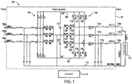
- FIG. 1 is a schematic diagram of an online UPS 100 according to one aspect of the present invention.
- the UPS 100 includes a frame 101, plurality of inputs 102a-c, a converter 104, a positive DC bus 106, a negative DC bus 107, a first DC bus capacitor 115, a second DC bus capacitor 117, an inverter 108, a plurality of outputs (i.e., a first output 110a, a second output 110b, and a third output 110c), a neutral line 112, and a controller 114.
- Each of the plurality of inputs 102a-c is configured to be coupled to one phase of a three-phase power source.
- the converter 104 is coupled to each of the plurality of inputs 102a-c.
- the positive DC bus 106 and the negative DC bus 107 are coupled between the converter 104 and the inverter 108.
- the first DC bus capacitor 115 is coupled between the positive DC bus 106 and the neutral line 112.
- the second DC bus capacitor 117 is coupled between the negative DC bus 107 and the neutral line 112.
- the inverter 108 is also coupled to each of the plurality of outputs 110a-c.
- the first output 110a and the second output 110b are configured to be coupled to a load 111.
- the third output 110c is coupled to the neutral line 112.
- the inverter 108 includes a first plurality of switches coupled between the DC busses 106, 107 and the plurality of outputs 110a-c and a second plurality of switches coupled between the neutral line 112 and the plurality of outputs 110a-c.
- the first plurality of switches includes a first switch 116 coupled between the positive DC bus 106 and the first output 110a via a first phase line 113a, a second switch 118 coupled between the positive DC bus 106 and the second output 110b via a second phase line 113b, a third switch 120 coupled between the positive DC bus 106 and the third output 110c via a third phase line 113c, a fourth switch 122 coupled between the negative DC bus 107 and the first output 110a via the first phase line 113a, a fifth switch 124 coupled between the negative DC bus 107 and the second output 110b via the second phase line 113b, and a sixth switch 126 coupled between the negative DC bus 107 and the third output 110c via the third phase line 113c.
- the second plurality of switches includes a seventh switch 128 and eighth switch 130, coupled in series between the neutral line 112 and the first output 110a via the first phase line 113a , a ninth switch 132 and tenth switch 134, coupled in series between the neutral line 112 and the second output 110b via the second phase line 113b, and an eleventh switch 136 and twelfth switch 138, coupled in series between the neutral line 112 and the third output 110c via the third phase line 113c.
- each switch 116-138 is a Bipolar Junction Transistor (BJT); however, in other embodiments, another appropriate type of switch or transistor (e.g., a Metal-Oxide-Semiconductor Field-Effect Transistor (MOSFET)) may be utilized.
- each switch 116-138 includes a parallel diode coupled between its collector and emitter.
- the controller 114 is coupled to the inputs 102a-c, the outputs 110a-c, the converter 104, the positive DC bus 106, the negative DC bus 107, and the inverter 108.
- the UPS 100 is also configured to be coupled to a battery (e.g., at the DC busses 106, 107 or via a DC/DC converter).
- Each input 102a-c is configured to receive one phase of the three-phase power provided by the 3-phase power source.
- the controller 114 monitors the input AC power received by the inputs 102a-c and is configured to operate the UPS 100 in different modes of operation based on the status of the received input AC power.
- the controller 114 operates the UPS 100 in an online mode of operation.
- AC power from the inputs 102a-c is provided to the converter 104.
- the converter 104 is a Power Factor Correction converter; however, in other embodiments, other types of converters may be utilized.
- the controller 114 operates the converter 104 to convert the input AC power into DC power and provide the DC power to the positive DC bus 106 and the negative DC bus 107.
- DC power is also provided from the converter 104 to a battery to charge the battery.
- DC power from the DC busses 106, 107 is provided to the battery via a DC/DC converter to charge the battery.
- the inverter 108 receives DC power from the positive DC bus 106 and the negative DC bus 107, and the controller 114 operates the inverter 108 to convert the DC power into regulated AC power and provide regulated AC power to a load 111 coupled to the first output 110a (and the first phase line 113a) and the second output 110b (and the second phase line 113b).
- the controller 114 When AC power provided to the inputs 102a-c is not acceptable (i.e., below an input power threshold), the controller 114 operates the UPS 100 in a backup mode of operation.
- DC power from a DC power source e.g., a battery
- the inverter 108 receives the DC power from the positive DC bus 106 and the negative DC bus 107, and the controller 114 operates the inverter 108 to convert the DC power into regulated AC power and provide the regulated AC power to the first output 110a via the first phase line 113a and the second output 110b via the second phase line 113b.
- regulated output AC power is provided to a load 111 via the first phase line 113a/first output 110a and the second phase line 113b/second output 110b.
- the inverter 108 is configured to provide a first portion of the output AC power (e.g., a first current) to the load 111 via the first phase line 113a/first output 110a and to provide a second portion of the output AC power (e.g., a second current) to the load 111 via the second phase line 113b/second output 110b.
- the first portion and the second portion are combined to provide the regulated output AC power to the load 111.
- the inverter 108 is also operated by the controller 114 to reduce current in the neutral line 112. More specifically, current in the neutral line 112 can be reduced by operating the inverter 108 to generate current between the load 111 and the neutral line 112 via the third output 113c and the inverter 108. Current between the load 111 and the third output 110c can be controlled by operating the eleventh switch 136, the twelfth switch 138, the third switch 120, and the sixth switch 126.
- the current can be modulated by turning the eleventh switch 136 constantly on and operating the third switch 120 with a Pulse Width Modulation (PWM) signal.
- PWM Pulse Width Modulation
- the current can be modulated by turning the twelfth switch 138 constantly on and operating the sixth switch 126 with a Pulse Width Modulation (PWM) signal.
- the third phase line 113c can be operated to draw current (i.e., current through the output 110c) at a desired level and in counter-phase to the current provided to the load by the first phase line 113a and the second phase line 113b (i.e., the current through the first output 110a and the current through the second output 110b).
- a first portion of the return current between the load 111 and the system 100 is passed directly between the neutral line 112 and the load 111 and a second portion of the return current between the load 111 and the system 100 is passed through the third phase line 113c.
- half of the load current ILOAD/2
- half of the load current ILOAD/2
- the division of the load current can be configured differently.
- the third phase line 113c of the inverter 108 can also be utilized as a bus balancer to move energy between the positive DC bus 106 and the negative DC bus 107.
- ripple current in the DC-bus capacitors 115, 117 can partially be shared between the two DC busses 106, 107, thus lowering the RMS ripple current in each capacitor 115, 117.
- the controller 114 operates the eleventh switch 136 and the twelfth switch 138 to open and operates the third switch 120 and the sixth switch 126 to transfer desired energy between the positive DC bus 106 and the negative DC bus 107.
- ripple current in the DC-bus capacitors 115, 117 can be shared between the two DC busses 106, 107.
- FIG. 2 is a graph 200 illustrating operation of the UPS where the first phase line 113a and the second phase line 113b are providing power to the load 111 and the third phase line 113c is inactive.
- the graph 200 includes a first trace 202 illustrating ripple current in the positive DC-bus capacitor 115 and a second trace 203 illustrating RMS ripple current (e.g., about 71A).
- the first trace 202 includes a large 50Hz ripple during the positive half-period.
- the graph 200 includes a third trace 204 illustrating voltage on the positive DC bus 106, a fourth trace 208 illustrating voltage on the negative DC bus 107, and a fifth trace 206 illustrating output voltage provided to the load 111.
- There is a voltage ripple on each bus 106, 107 (e.g., around 68V peak-peak per DC-bus).
- the graph 200 includes a sixth trace 210 illustrating current drawn from the positive DC-bus 106 by the first phase line 113a to the first output 110a, a seventh trace 212 illustrating current drawn from the positive DC-bus 106 by the second phase line 113b to the second output 110b, and an eighth trace 213 illustrating current through the third phase line 113c to the third output 110c.
- the current through the first phase line 113a is the same as the current through the second phase line 113b, while the current through the third phase line 113c is zero.
- the graph 200 includes a ninth trace 214 illustrating current through the neutral line 112. The current through the neutral line is equal to the load current.
- the graph 200 includes a tenth trace 216, an eleventh trace 218, and a twelfth trace 220, each illustrating the current provided to the positive DC bus 106 by one of the input phases 102a-c.
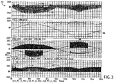
- FIG. 3 is a graph 300 illustrating operation of the UPS where the first phase line 113a and second phase line 113 are providing power to the load 111 and the third phase line 113c is active (e.g., as discussed above).
- the graph 300 includes a first trace 302 illustrating ripple current in the positive DC-bus capacitor 115 and a second trace 303 illustrating RMS ripple current.
- the graph 300 includes a third trace 304 illustrating voltage on the positive DC bus 106, a fourth trace 308 illustrating voltage on the negative DC bus 107, and a fifth trace 306 illustrating output voltage provided to the load 111.
- There is a voltage ripple on each bus 106, 107 (e.g., around 43V peak-peak per DC-bus).
- the graph 300 includes a sixth trace 310 illustrating current drawn from the positive DC-bus 106 by the first phase line 113a to the first output 110a, a seventh trace 312 illustrating current drawn from the positive DC-bus 106 by the second phase line 113b to the second output 110b, and an eighth trace 313 illustrating current through the third phase line 113c to the third output 110c.
- the current through the first phase line 113a is the same as the current through the second phase line 113b.
- the graph 300 includes a ninth trace 314 illustrating current through the neutral line 112.
- the graph 300 includes a tenth trace 316, an eleventh trace 318, and a twelfth trace 320, each illustrating the current provided to the positive DC bus 106 by one of the input phases 102a-c.
- the third phase line 113c can be operated to reduce current in the neutral line 112.
- the eleventh switch 136, the twelfth switch 138, the third switch 120, and the sixth switch 126 are operated such that the current through the third phase line 113c (i.e., the eighth trace 313) is in opposite phase to the current 314 in the neutral line 112.
- the current 314 through the neutral line 112 is thus reduced in half (e.g., when compared to the graph 200 of FIG. 2 ) and the stress on the neutral line 112 is reduced.
- the third phase line 113c of the inverter 108 can be utilized as a bus balancer to move energy between the positive DC bus 106 and the negative DC bus 107.
- ripple current in the DC-bus capacitors 115, 117 can be shared between the two DC busses 106, 107. For instance, as shown in FIG.
- the RMS current 303 in the positive DC bus capacitor 115 is reduced from 71A (e.g., from FIG. 2 ) to 63A.
- the DC-bus ripple voltage can also be reduced.
- the DC-bus ripple voltage has dropped from 68V peak-peak (e.g., from FIG. 2 ) to 43V.
- the 100Hz equivalent ripple current is also reduced (e.g., when compared to the implementation of FIG. 2 ).
- the controller 114 is configured to monitor and control operation of the UPS 100. Using data stored in associated memory, the controller 114 is operable to execute one or more instructions that may result in the manipulation of one or more switches' conductive states.
- the controller 114 can include one or more processors or other types of controllers.
- the controller 114 may perform a portion of the functions discussed herein on a processor, and perform another portion using an Application-Specific Integrated Circuit (ASIC) tailored to perform particular operations. Examples in accordance with the present invention may perform the operations described herein using many specific combinations of hardware and software and the invention is not limited to any particular combination of hardware and software components.
- ASIC Application-Specific Integrated Circuit
- the UPS 100 is configured to operate in a 3:1 configuration where power is provided to a load 111 via two phase lines 113a, 113b and the third phase line 113c is operated as a return line/bus balancer.
- the first output 110a and the second output 110b are coupled together within the frame 101 of the UPS and the third output 110c is coupled to the neutral line 112 within the frame 101.
- the UPS 100 can also be configured to operate in a 3:1 configuration where all three phase lines are coupled to provide power to a load.
- the first output 110a, the second output 110b, and the third output 110c can be coupled together within the frame 101 of the UPS.
- a UPS topology is described herein that can be operated in a 3:1 configuration while reducing DC-bus capacitor ripple current and reducing current in the neutral wire.
- the UPS is operated by coupling two output phases to a load in parallel and utilizing the third phase as a bus balancer by connecting it to the neutral line.
- the output power of a UPS operating in 3:1 configuration can be increased by around 50% (e.g., when compared to a UPS in 3:1 configuration that does not implement the bus-balancer configuration).
Landscapes
- Engineering & Computer Science (AREA)
- Power Engineering (AREA)
- Business, Economics & Management (AREA)
- Emergency Management (AREA)
- Inverter Devices (AREA)
- Supply And Distribution Of Alternating Current (AREA)
Claims (15)
- Une ASI (100) comprenant :une pluralité d'entrées (102a, 102b, 102c) configurées pour être couplées à une source de puissance CA triphasée et pour recevoir de la puissance d'entrée triphasée de la source de puissance CA triphasée ;un convertisseur (104) couplé à la pluralité d'entrées et configuré pour convertir la puissance d'entrée triphasée en puissance CC ;un bus CC positif (106) couplé au convertisseur ;un bus CC négatif (107) couplé au convertisseur ;un onduleur (108) couplé au bus CC positif et au bus CC négatif et configuré pour convertir la puissance CC reçue du bus CC positif et du bus CC négatif en puissance CA de sortie ;une première sortie (110a) couplée à l'onduleur et configurée pour être couplée à une charge monophasée (111) et pour fournir une première portion de la puissance CA de sortie de l'onduleur à la charge monophasée ;une deuxième sortie (110b) couplée à l'onduleur et configurée pour être couplée à la charge monophasée, en parallèle avec la première sortie, et pour fournir une deuxième portion de la puissance CA de sortie de l'onduleur à la charge monophasée ;une ligne neutre (112) configurée pour être couplée à la charge monophasée pour la fourniture d'un chemin pour un courant de retour du courant à fournir à la charge monophasée par l'intermédiaire des première et deuxième sorties ;une troisième sortie (110c) configurée pour être couplée à l'onduleur ; etun organe de commande (114) couplé à l'onduleur ;caractérisée en ce que :le convertisseur est un convertisseur PFC (Power Factor Correction, correction du facteur de puissance) ; etl'organe de commande est configuré pour actionner l'onduleur pour absorber au moins une portion dudit courant de retour.
- L'ASI de la revendication 1, dans laquelle l'onduleur comprend un premier interrupteur couplé entre la troisième sortie et la ligne neutre, et dans laquelle dans l'actionnement de l'onduleur pour absorber au moins une portion dudit courant de retour par l'intermédiaire de la troisième sortie, l'organe de commande est en outre configuré pour actionner le premier interrupteur pour coupler la troisième sortie à la ligne neutre.
- L'ASI de la revendication 2, dans laquelle l'organe de commande est en outre configuré pour actionner l'onduleur pour moduler le courant absorbé par l'intermédiaire de la troisième sortie à un niveau souhaité.
- L'ASI de la revendication 3, dans laquelle l'organe de commande est en outre configuré pour actionner l'onduleur pour moduler le courant absorbé par l'intermédiaire de la troisième sortie afin qu'il soit en opposition de phase avec un courant de sortie de la première portion de la puissance CA de sortie fournie à la charge monophasée par l'intermédiaire de la première sortie et avec un courant de sortie de la deuxième portion de la puissance CA de sortie fournie à la charge monophasée par l'intermédiaire de la deuxième sortie.
- L'ASI de la revendication 4, dans laquelle l'onduleur comprend en outre :un deuxième interrupteur couplé entre la troisième sortie et le bus CC positif ; etun troisième interrupteur couplé entre la troisième sortie et le bus CC négatif,dans laquelle dans l'actionnement de l'onduleur pour moduler le courant absorbé par l'intermédiaire de la troisième sortie, l'organe de commande est en outre configuré pour actionner le deuxième interrupteur pour générer un courant entre le bus CC positif et la troisième sortie et pour actionner le troisième interrupteur pour générer un courant entre le bus CC négatif et la troisième sortie.
- L'ASI de la revendication 5, dans laquelle l'organe de commande est en outre configuré pour actionner l'onduleur comme un équilibreur de bus pour transférer de l'énergie entre le bus CC positif et le bus CC négatif.
- L'ASI de la revendication 6, comprenant en outre :un condensateur de bus positif couplé entre le bus CC positif et la ligne neutre,dans laquelle dans l'actionnement de l'onduleur comme un équilibreur de bus, l'organe de commande est en outre configuré pour actionner l'onduleur pour partager un courant ondulé dans le condensateur de bus CC positif avec le bus CC négatif, etun condensateur de bus négatif couplé entre le bus CC négatif et la ligne neutre,dans laquelle dans l'actionnement de l'onduleur comme un équilibreur de bus, l'organe de commande est en outre configuré pour actionner l'onduleur pour partager un courant ondulé dans le condensateur de bus CC négatif avec le bus CC positif.
- L'ASI de la revendication 6, dans laquelle dans l'actionnement de l'onduleur comme un équilibreur de bus, l'organe de commande est en outre configuré pour actionner le premier interrupteur pour découpler la troisième sortie de la ligne neutre et pour actionner le deuxième interrupteur et le troisième interrupteur pour transférer de l'énergie entre le bus CC positif et le bus CC négatif.
- Un procédé pour l'actionnement d'une ASI (100) comprenant une pluralité d'entrées (102a, 102b, 102c) configurées pour être couplées à une source de puissance CA triphasée, un convertisseur PFC (104) couplé à la pluralité d'entrées, un bus CC positif (106) couplé au convertisseur PFC, un bus CC négatif (107) couplé au convertisseur PFC, un onduleur (108) couplé aux bus CC positif et négatif, une première sortie (110a) couplée à l'onduleur, une deuxième sortie (110b) couplée à l'onduleur, une troisième sortie (110c) couplée à l'onduleur, et une ligne neutre (112),
le procédé comprenant :le couplage de la première sortie et de la deuxième sortie à une charge monophasée (111) en parallèle ;le couplage de la ligne neutre à la charge monophasée ;le couplage de la troisième sortie à la ligne neutre ;la réception de puissance CA d'entrée triphasée au niveau de la pluralité d'entrées en provenance de la source de puissance CA triphasée ;la conversion, avec le convertisseur PFC, de la puissance CA d'entrée triphasée en puissance CC ;la fourniture de la puissance CC à l'onduleur par l'intermédiaire des bus CC positif et négatif ;la conversion de la puissance CC en provenance des bus CC positif et négatif en puissance CA de sortie ;la fourniture d'une première portion de la puissance CA de sortie à la charge par l'intermédiaire de la première sortie ;la fourniture d'une deuxième portion de la puissance CA de sortie à la charge par l'intermédiaire de la deuxième sortie ;l'absorption, par l'intermédiaire de la ligne neutre, d'une première portion d'un courant de retour du courant fourni à la charge monophasée par l'intermédiaire des première et deuxième sorties ;l'absorption, par l'intermédiaire de la troisième sortie, d'une deuxième portion dudit courant de retour. - Le procédé de la revendication 9, dans lequel l'absorption de la deuxième portion dudit courant de retour par l'intermédiaire de la troisième sortie inclut le couplage sélectif de la troisième sortie à la ligne neutre par l'intermédiaire d'un premier interrupteur de l'onduleur.
- Le procédé de la revendication 10, dans lequel l'absorption de la deuxième portion dudit courant de retour par l'intermédiaire de la troisième sortie inclut la modulation de la deuxième portion du courant de retour à un niveau souhaité.
- Le procédé de la revendication 11, dans lequel la modulation de la deuxième portion du courant de retour inclut la modulation de la deuxième portion du courant de retour pour qu'elle soit en opposition de phase avec un courant de sortie de la première portion de la puissance CA de sortie fournie à la charge monophasée par l'intermédiaire de la première sortie et avec un courant de sortie de la deuxième portion de la puissance CA de sortie fournie à la charge monophasée par l'intermédiaire de la deuxième sortie.
- Le procédé de la revendication 12, dans lequel la modulation de la deuxième portion du courant de retour inclut la génération, avec un deuxième interrupteur, d'un courant entre la troisième sortie et le bus CC positif et la génération, avec un troisième interrupteur, d'un courant entre la troisième sortie et le bus CC négatif.
- Le procédé de la revendication 13, comprenant en outre l'actionnement de l'onduleur comme un équilibreur de bus pour transférer de l'énergie entre le bus CC positif et le bus CC négatif.
- Le procédé de la revendication 14, dans lequel l'actionnement de l'onduleur comme un équilibreur de bus inclut :l'actionnement du premier interrupteur pour découpler la troisième sortie de la ligne neutre ; etl'actionnement du deuxième interrupteur et du troisième interrupteur pour transférer de l'énergie entre le bus CC positif et le bus CC négatif.
Applications Claiming Priority (1)
| Application Number | Priority Date | Filing Date | Title |
|---|---|---|---|
| US16/206,229 US10784714B2 (en) | 2018-11-30 | 2018-11-30 | 3 phase UPS bus balancer |
Publications (2)
| Publication Number | Publication Date |
|---|---|
| EP3661011A1 EP3661011A1 (fr) | 2020-06-03 |
| EP3661011B1 true EP3661011B1 (fr) | 2021-07-07 |
Family
ID=68583192
Family Applications (1)
| Application Number | Title | Priority Date | Filing Date |
|---|---|---|---|
| EP19209439.9A Active EP3661011B1 (fr) | 2018-11-30 | 2019-11-15 | Équilibreur de bus d'alimentation sans coupure triphasée |
Country Status (3)
| Country | Link |
|---|---|
| US (1) | US10784714B2 (fr) |
| EP (1) | EP3661011B1 (fr) |
| CN (1) | CN111262330B (fr) |
Families Citing this family (2)
| Publication number | Priority date | Publication date | Assignee | Title |
|---|---|---|---|---|
| CN112838773A (zh) * | 2019-11-25 | 2021-05-25 | 开利公司 | 具有不对称半导体额定值布置的功率模块和转换器 |
| EP4382928A1 (fr) * | 2022-12-09 | 2024-06-12 | ABB E-mobility B.V. | Procédé de détection d'un commutateur à courant alternatif bloqué dans un convertisseur |
Family Cites Families (13)
| Publication number | Priority date | Publication date | Assignee | Title |
|---|---|---|---|---|
| AU2000280373A1 (en) * | 2000-09-01 | 2002-03-22 | Powerware Corporation | Inverter having center switch and uninterruptible power supply implementing same |
| JP2004336885A (ja) * | 2003-05-07 | 2004-11-25 | Toyota Motor Corp | 動力出力装置、モータ駆動方法およびモータの駆動制御をコンピュータに実行させるためのプログラムを記録したコンピュータ読取り可能な記録媒体 |
| US7688048B2 (en) * | 2007-02-21 | 2010-03-30 | American Power Conversion Corporation | 3-phase high power UPS |
| US20100172166A1 (en) * | 2009-01-07 | 2010-07-08 | Tejinder Singh | Plug-in neutral regulator for 3-phase 4-wire inverter/converter system |
| US9203323B2 (en) * | 2011-09-22 | 2015-12-01 | Renewable Power Conversion, Inc. | Very high efficiency uninterruptible power supply |
| US10277067B2 (en) | 2013-10-30 | 2019-04-30 | Schneider Electric It Corporation | Power supply control |
| CN106664027B (zh) | 2014-05-01 | 2019-06-14 | 施耐德电气It公司 | 供电控制 |
| CN106663940B (zh) | 2014-06-27 | 2019-08-06 | 施耐德电气It公司 | 三级电力拓扑 |
| US10211750B2 (en) * | 2016-02-12 | 2019-02-19 | Schneider Electric It Corporation | Apparatus and method for low frequency power inverter |
| US10211672B2 (en) * | 2016-10-13 | 2019-02-19 | Schneider Electric It Corporation | DC-link bus balancer |
| CN108418440B (zh) | 2018-05-08 | 2024-08-06 | 国网电力科学研究院武汉南瑞有限责任公司 | 单/三相两用三电平低频干燥电源 |
| US10948550B2 (en) | 2018-07-03 | 2021-03-16 | Schneider Electric It Corporation | Power device with electrolytic capacitors |
| US10439512B1 (en) | 2018-09-27 | 2019-10-08 | Schneider Electric It Corporation | Clamp circuit to reduce overshoot in power converters |
-
2018
- 2018-11-30 US US16/206,229 patent/US10784714B2/en active Active
-
2019
- 2019-11-15 EP EP19209439.9A patent/EP3661011B1/fr active Active
- 2019-11-29 CN CN201911201538.8A patent/CN111262330B/zh active Active
Also Published As
| Publication number | Publication date |
|---|---|
| CN111262330A (zh) | 2020-06-09 |
| CN111262330B (zh) | 2023-10-27 |
| US20200177020A1 (en) | 2020-06-04 |
| EP3661011A1 (fr) | 2020-06-03 |
| US10784714B2 (en) | 2020-09-22 |
Similar Documents
| Publication | Publication Date | Title |
|---|---|---|
| EP3309927B1 (fr) | Équilibreur de bus à liaison cc | |
| AU2012302148B2 (en) | Twin boost converter with integrated charger for ups | |
| US11157430B2 (en) | DC-DC power converter with four way power conversion | |
| US10630104B2 (en) | Automatic current balancing for power systems | |
| US12191706B2 (en) | Method and system to control multiple sources of energy using an uninterruptible power supply | |
| US11283288B2 (en) | Integrated DC to DC converter UPS topology | |
| US10833601B2 (en) | Multi-level inverter | |
| EP3384577A1 (fr) | Partage de charge via une dérivation d'unité d'alimentation permanente (ups) automatique | |
| US10461575B2 (en) | Multistate PWM command for 3 levels inverters | |
| EP3661011B1 (fr) | Équilibreur de bus d'alimentation sans coupure triphasée | |
| EP3661008A1 (fr) | Batterie d'aviation avec extrémité avant pfc de commutateur en courant alternatif pour alimentation sans coupure (ups) | |
| EP2941805B1 (fr) | Commande d'alimentation électrique | |
| EP2761720B1 (fr) | Appareil d'alimentation en courant alternatif et procédés permettant de fournir des formes d'onde de tension variables pour des conditions de variation brusque de la charge | |
| US11043838B2 (en) | System and method to reduce converter emissions | |
| Sousa et al. | Single-phase shunt active power filter with UPS operation using a bidirectional Dc-Dc converter for energy storage interface | |
| JP3237220B2 (ja) | 高調波抑制装置 |
Legal Events
| Date | Code | Title | Description |
|---|---|---|---|
| PUAI | Public reference made under article 153(3) epc to a published international application that has entered the european phase |
Free format text: ORIGINAL CODE: 0009012 |
|
| STAA | Information on the status of an ep patent application or granted ep patent |
Free format text: STATUS: THE APPLICATION HAS BEEN PUBLISHED |
|
| AK | Designated contracting states |
Kind code of ref document: A1 Designated state(s): AL AT BE BG CH CY CZ DE DK EE ES FI FR GB GR HR HU IE IS IT LI LT LU LV MC MK MT NL NO PL PT RO RS SE SI SK SM TR |
|
| AX | Request for extension of the european patent |
Extension state: BA ME |
|
| STAA | Information on the status of an ep patent application or granted ep patent |
Free format text: STATUS: REQUEST FOR EXAMINATION WAS MADE |
|
| 17P | Request for examination filed |
Effective date: 20201203 |
|
| RBV | Designated contracting states (corrected) |
Designated state(s): AL AT BE BG CH CY CZ DE DK EE ES FI FR GB GR HR HU IE IS IT LI LT LU LV MC MK MT NL NO PL PT RO RS SE SI SK SM TR |
|
| RIC1 | Information provided on ipc code assigned before grant |
Ipc: H02M 5/458 20060101ALI20201217BHEP Ipc: H02J 9/06 20060101AFI20201217BHEP Ipc: G05F 1/44 20060101ALN20201217BHEP |
|
| GRAP | Despatch of communication of intention to grant a patent |
Free format text: ORIGINAL CODE: EPIDOSNIGR1 |
|
| STAA | Information on the status of an ep patent application or granted ep patent |
Free format text: STATUS: GRANT OF PATENT IS INTENDED |
|
| INTG | Intention to grant announced |
Effective date: 20210203 |
|
| RAP3 | Party data changed (applicant data changed or rights of an application transferred) |
Owner name: SCHNEIDER ELECTRIC IT CORPORATION |
|
| GRAS | Grant fee paid |
Free format text: ORIGINAL CODE: EPIDOSNIGR3 |
|
| GRAA | (expected) grant |
Free format text: ORIGINAL CODE: 0009210 |
|
| STAA | Information on the status of an ep patent application or granted ep patent |
Free format text: STATUS: THE PATENT HAS BEEN GRANTED |
|
| AK | Designated contracting states |
Kind code of ref document: B1 Designated state(s): AL AT BE BG CH CY CZ DE DK EE ES FI FR GB GR HR HU IE IS IT LI LT LU LV MC MK MT NL NO PL PT RO RS SE SI SK SM TR |
|
| REG | Reference to a national code |
Ref country code: GB Ref legal event code: FG4D |
|
| REG | Reference to a national code |
Ref country code: AT Ref legal event code: REF Ref document number: 1409520 Country of ref document: AT Kind code of ref document: T Effective date: 20210715 |
|
| REG | Reference to a national code |
Ref country code: DE Ref legal event code: R096 Ref document number: 602019005932 Country of ref document: DE |
|
| REG | Reference to a national code |
Ref country code: IE Ref legal event code: FG4D |
|
| REG | Reference to a national code |
Ref country code: LT Ref legal event code: MG9D |
|
| REG | Reference to a national code |
Ref country code: NL Ref legal event code: MP Effective date: 20210707 |
|
| REG | Reference to a national code |
Ref country code: AT Ref legal event code: MK05 Ref document number: 1409520 Country of ref document: AT Kind code of ref document: T Effective date: 20210707 |
|
| PG25 | Lapsed in a contracting state [announced via postgrant information from national office to epo] |
Ref country code: SE Free format text: LAPSE BECAUSE OF FAILURE TO SUBMIT A TRANSLATION OF THE DESCRIPTION OR TO PAY THE FEE WITHIN THE PRESCRIBED TIME-LIMIT Effective date: 20210707 Ref country code: RS Free format text: LAPSE BECAUSE OF FAILURE TO SUBMIT A TRANSLATION OF THE DESCRIPTION OR TO PAY THE FEE WITHIN THE PRESCRIBED TIME-LIMIT Effective date: 20210707 Ref country code: ES Free format text: LAPSE BECAUSE OF FAILURE TO SUBMIT A TRANSLATION OF THE DESCRIPTION OR TO PAY THE FEE WITHIN THE PRESCRIBED TIME-LIMIT Effective date: 20210707 Ref country code: LT Free format text: LAPSE BECAUSE OF FAILURE TO SUBMIT A TRANSLATION OF THE DESCRIPTION OR TO PAY THE FEE WITHIN THE PRESCRIBED TIME-LIMIT Effective date: 20210707 Ref country code: BG Free format text: LAPSE BECAUSE OF FAILURE TO SUBMIT A TRANSLATION OF THE DESCRIPTION OR TO PAY THE FEE WITHIN THE PRESCRIBED TIME-LIMIT Effective date: 20211007 Ref country code: AT Free format text: LAPSE BECAUSE OF FAILURE TO SUBMIT A TRANSLATION OF THE DESCRIPTION OR TO PAY THE FEE WITHIN THE PRESCRIBED TIME-LIMIT Effective date: 20210707 Ref country code: FI Free format text: LAPSE BECAUSE OF FAILURE TO SUBMIT A TRANSLATION OF THE DESCRIPTION OR TO PAY THE FEE WITHIN THE PRESCRIBED TIME-LIMIT Effective date: 20210707 Ref country code: HR Free format text: LAPSE BECAUSE OF FAILURE TO SUBMIT A TRANSLATION OF THE DESCRIPTION OR TO PAY THE FEE WITHIN THE PRESCRIBED TIME-LIMIT Effective date: 20210707 Ref country code: PT Free format text: LAPSE BECAUSE OF FAILURE TO SUBMIT A TRANSLATION OF THE DESCRIPTION OR TO PAY THE FEE WITHIN THE PRESCRIBED TIME-LIMIT Effective date: 20211108 Ref country code: NO Free format text: LAPSE BECAUSE OF FAILURE TO SUBMIT A TRANSLATION OF THE DESCRIPTION OR TO PAY THE FEE WITHIN THE PRESCRIBED TIME-LIMIT Effective date: 20211007 Ref country code: NL Free format text: LAPSE BECAUSE OF FAILURE TO SUBMIT A TRANSLATION OF THE DESCRIPTION OR TO PAY THE FEE WITHIN THE PRESCRIBED TIME-LIMIT Effective date: 20210707 |
|
| PG25 | Lapsed in a contracting state [announced via postgrant information from national office to epo] |
Ref country code: PL Free format text: LAPSE BECAUSE OF FAILURE TO SUBMIT A TRANSLATION OF THE DESCRIPTION OR TO PAY THE FEE WITHIN THE PRESCRIBED TIME-LIMIT Effective date: 20210707 Ref country code: LV Free format text: LAPSE BECAUSE OF FAILURE TO SUBMIT A TRANSLATION OF THE DESCRIPTION OR TO PAY THE FEE WITHIN THE PRESCRIBED TIME-LIMIT Effective date: 20210707 Ref country code: GR Free format text: LAPSE BECAUSE OF FAILURE TO SUBMIT A TRANSLATION OF THE DESCRIPTION OR TO PAY THE FEE WITHIN THE PRESCRIBED TIME-LIMIT Effective date: 20211008 |
|
| REG | Reference to a national code |
Ref country code: DE Ref legal event code: R097 Ref document number: 602019005932 Country of ref document: DE |
|
| PG25 | Lapsed in a contracting state [announced via postgrant information from national office to epo] |
Ref country code: DK Free format text: LAPSE BECAUSE OF FAILURE TO SUBMIT A TRANSLATION OF THE DESCRIPTION OR TO PAY THE FEE WITHIN THE PRESCRIBED TIME-LIMIT Effective date: 20210707 |
|
| PLBE | No opposition filed within time limit |
Free format text: ORIGINAL CODE: 0009261 |
|
| STAA | Information on the status of an ep patent application or granted ep patent |
Free format text: STATUS: NO OPPOSITION FILED WITHIN TIME LIMIT |
|
| PG25 | Lapsed in a contracting state [announced via postgrant information from national office to epo] |
Ref country code: SM Free format text: LAPSE BECAUSE OF FAILURE TO SUBMIT A TRANSLATION OF THE DESCRIPTION OR TO PAY THE FEE WITHIN THE PRESCRIBED TIME-LIMIT Effective date: 20210707 Ref country code: SK Free format text: LAPSE BECAUSE OF FAILURE TO SUBMIT A TRANSLATION OF THE DESCRIPTION OR TO PAY THE FEE WITHIN THE PRESCRIBED TIME-LIMIT Effective date: 20210707 Ref country code: RO Free format text: LAPSE BECAUSE OF FAILURE TO SUBMIT A TRANSLATION OF THE DESCRIPTION OR TO PAY THE FEE WITHIN THE PRESCRIBED TIME-LIMIT Effective date: 20210707 Ref country code: EE Free format text: LAPSE BECAUSE OF FAILURE TO SUBMIT A TRANSLATION OF THE DESCRIPTION OR TO PAY THE FEE WITHIN THE PRESCRIBED TIME-LIMIT Effective date: 20210707 Ref country code: CZ Free format text: LAPSE BECAUSE OF FAILURE TO SUBMIT A TRANSLATION OF THE DESCRIPTION OR TO PAY THE FEE WITHIN THE PRESCRIBED TIME-LIMIT Effective date: 20210707 Ref country code: AL Free format text: LAPSE BECAUSE OF FAILURE TO SUBMIT A TRANSLATION OF THE DESCRIPTION OR TO PAY THE FEE WITHIN THE PRESCRIBED TIME-LIMIT Effective date: 20210707 |
|
| 26N | No opposition filed |
Effective date: 20220408 |
|
| PG25 | Lapsed in a contracting state [announced via postgrant information from national office to epo] |
Ref country code: MC Free format text: LAPSE BECAUSE OF FAILURE TO SUBMIT A TRANSLATION OF THE DESCRIPTION OR TO PAY THE FEE WITHIN THE PRESCRIBED TIME-LIMIT Effective date: 20210707 |
|
| PG25 | Lapsed in a contracting state [announced via postgrant information from national office to epo] |
Ref country code: LU Free format text: LAPSE BECAUSE OF NON-PAYMENT OF DUE FEES Effective date: 20211115 Ref country code: IT Free format text: LAPSE BECAUSE OF FAILURE TO SUBMIT A TRANSLATION OF THE DESCRIPTION OR TO PAY THE FEE WITHIN THE PRESCRIBED TIME-LIMIT Effective date: 20210707 Ref country code: BE Free format text: LAPSE BECAUSE OF NON-PAYMENT OF DUE FEES Effective date: 20211130 |
|
| REG | Reference to a national code |
Ref country code: BE Ref legal event code: MM Effective date: 20211130 |
|
| PG25 | Lapsed in a contracting state [announced via postgrant information from national office to epo] |
Ref country code: IE Free format text: LAPSE BECAUSE OF NON-PAYMENT OF DUE FEES Effective date: 20211115 |
|
| PG25 | Lapsed in a contracting state [announced via postgrant information from national office to epo] |
Ref country code: CY Free format text: LAPSE BECAUSE OF FAILURE TO SUBMIT A TRANSLATION OF THE DESCRIPTION OR TO PAY THE FEE WITHIN THE PRESCRIBED TIME-LIMIT Effective date: 20210707 |
|
| REG | Reference to a national code |
Ref country code: CH Ref legal event code: PL |
|
| PG25 | Lapsed in a contracting state [announced via postgrant information from national office to epo] |
Ref country code: LI Free format text: LAPSE BECAUSE OF NON-PAYMENT OF DUE FEES Effective date: 20221130 Ref country code: HU Free format text: LAPSE BECAUSE OF FAILURE TO SUBMIT A TRANSLATION OF THE DESCRIPTION OR TO PAY THE FEE WITHIN THE PRESCRIBED TIME-LIMIT; INVALID AB INITIO Effective date: 20191115 Ref country code: CH Free format text: LAPSE BECAUSE OF NON-PAYMENT OF DUE FEES Effective date: 20221130 |
|
| PG25 | Lapsed in a contracting state [announced via postgrant information from national office to epo] |
Ref country code: MK Free format text: LAPSE BECAUSE OF FAILURE TO SUBMIT A TRANSLATION OF THE DESCRIPTION OR TO PAY THE FEE WITHIN THE PRESCRIBED TIME-LIMIT Effective date: 20210707 |
|
| PG25 | Lapsed in a contracting state [announced via postgrant information from national office to epo] |
Ref country code: MT Free format text: LAPSE BECAUSE OF FAILURE TO SUBMIT A TRANSLATION OF THE DESCRIPTION OR TO PAY THE FEE WITHIN THE PRESCRIBED TIME-LIMIT Effective date: 20210707 |
|
| PG25 | Lapsed in a contracting state [announced via postgrant information from national office to epo] |
Ref country code: TR Free format text: LAPSE BECAUSE OF FAILURE TO SUBMIT A TRANSLATION OF THE DESCRIPTION OR TO PAY THE FEE WITHIN THE PRESCRIBED TIME-LIMIT Effective date: 20210707 |
|
| PGFP | Annual fee paid to national office [announced via postgrant information from national office to epo] |
Ref country code: DE Payment date: 20251126 Year of fee payment: 7 |
|
| PGFP | Annual fee paid to national office [announced via postgrant information from national office to epo] |
Ref country code: GB Payment date: 20251125 Year of fee payment: 7 |
|
| PGFP | Annual fee paid to national office [announced via postgrant information from national office to epo] |
Ref country code: FR Payment date: 20251124 Year of fee payment: 7 |