EP3310680B1 - Zugbandbeutel mit arretierbarem zugband - Google Patents
Zugbandbeutel mit arretierbarem zugband Download PDFInfo
- Publication number
- EP3310680B1 EP3310680B1 EP16730373.4A EP16730373A EP3310680B1 EP 3310680 B1 EP3310680 B1 EP 3310680B1 EP 16730373 A EP16730373 A EP 16730373A EP 3310680 B1 EP3310680 B1 EP 3310680B1
- Authority
- EP
- European Patent Office
- Prior art keywords
- drawstring
- bag
- strip
- side part
- receiving area
- Prior art date
- Legal status (The legal status is an assumption and is not a legal conclusion. Google has not performed a legal analysis and makes no representation as to the accuracy of the status listed.)
- Active
Links
Images

Classifications
-
- B—PERFORMING OPERATIONS; TRANSPORTING
- B65—CONVEYING; PACKING; STORING; HANDLING THIN OR FILAMENTARY MATERIAL
- B65D—CONTAINERS FOR STORAGE OR TRANSPORT OF ARTICLES OR MATERIALS, e.g. BAGS, BARRELS, BOTTLES, BOXES, CANS, CARTONS, CRATES, DRUMS, JARS, TANKS, HOPPERS, FORWARDING CONTAINERS; ACCESSORIES, CLOSURES, OR FITTINGS THEREFOR; PACKAGING ELEMENTS; PACKAGES
- B65D33/00—Details of, or accessories for, sacks or bags
- B65D33/16—End- or aperture-closing arrangements or devices
- B65D33/28—Strings or strip-like closures, i.e. draw closures
-
- B—PERFORMING OPERATIONS; TRANSPORTING
- B65—CONVEYING; PACKING; STORING; HANDLING THIN OR FILAMENTARY MATERIAL
- B65F—GATHERING OR REMOVAL OF DOMESTIC OR LIKE REFUSE
- B65F1/00—Refuse receptacles; Accessories therefor
- B65F1/0006—Flexible refuse receptables, e.g. bags, sacks
- B65F1/002—Flexible refuse receptables, e.g. bags, sacks with means for opening or closing of the receptacle
Definitions
- the invention relates to a drawstring bag, formed from two side parts which are connected to one another on their side edge, a receiving area for a drawstring being provided in an opening-side area of the drawstring bag and a drawstring being arranged in this receiving area, the drawstring being connected on the one hand to the drawstring bag and on the other hand is freely accessible, according to the features of the preamble of claim 1.
- drawstring bags which are used, for example, as garbage bags, are generally known. From the US 4,813,794 A For example, a drawstring bag with the features of the preamble of claim 1 is known.
- the DE 93 07 723 U1 also shows a drawstring bag with a locking device.
- the drawstring bags are produced in a suitable manner in such a way that three sides of the drawstring bag are closed and thus form a container for holding anything.
- the fourth page is designed to be open to fill things into the drawstring bag. After filling, the drawstring bag can be closed in a manner known per se by pulling on the drawstring which is located in a receiving area. This pulling on the drawstring causes the drawstring to move out of the receiving area and the fourth open side of the drawstring bag to be pulled together, thereby closing the drawstring bag.
- the invention is therefore based on the object of improving a known drawstring bag in such a way that the drawstring bag, once closed, remains closed. If at all, it should only be possible to open the drawstring bag again with the application of higher forces or against resistance.
- a locking strip which is arranged on the drawstring and comes into contact with an opening edge of the receiving area for the drawstring when it has left this receiving area.
- the locking strip can be realized in various ways.
- the locking strip is glued to the drawstring.
- the locking strip is connected to the drawstring by means of a welded connection. Both options have the advantage that different ways are available to attach the locking strip to the drawstring.
- the locking strip can already be attached to the drawstring before it is threaded into the receiving area. Instead, it is conceivable to attach the locking strip to the drawstring when the drawstring has already been threaded into the receiving area.
- the locking strip is a material that is separate from the side part and the drawstring, in particular a plastic film, a paper strip or the like. This has the advantage that there is geometric freedom with regard to the size, the extent, the thickness and the material of the film.
- the locking strip is not formed as a separate part of the drawstring bag or drawstring, but is formed by a side part of the drawstring bag, the so-called mother material, preferably by a punching process.
- This has the advantage of particularly simple manufacture, since the drawstring bag can first be produced with the receiving area for the drawstring and then the drawstring can be arranged there in the receiving area. This is followed by punching out, perforating or the like of the locking strip from the side part, with the side part then being permanently connected to the drawstring at the same time or beforehand. This can again be done by an adhesive process, a welding process or the like.
- a connection between the locking strip and the side part of the drawstring bag like web-like or comparable connections, has the advantage that the drawstring is initially defined in the receiving area. Only after the drawstring bag has been filled can the freely accessible part of the drawstring be pulled, with the locking strip being released from the side part with the application of a minimum force. Instead, the locking strip can also be completely separated from the side part, even if it is formed by it.
- the receiving area for the tension band is designed as a loop and is formed by the upper edge of the side part.
- the receiving area for the tension band in the upper edge area of the side part is loop-shaped, only the upper edge of the side part being used to form the receiving area for the tension band.
- the receiving area for the tension band is designed as a support strip which is connected to the side part along its side edges.
- a strip-like material being used which is placed on the surface of the side part and its side edges are connected to the side part. This creates the receiving area for the drawstring.
- the locking strip is detached either from the side part or the support strip, or it is conceivable that the locking strip is again formed from a part of the side part or the support strip.
- the drawstring bag has a sinusoidal upper bag edge (so-called sinus bag), with a grip hole optionally being provided in the sinusoidal bag edge.
- the grip hole can be used to hang or carry the bag.
- the drawstring bags are designed, for example, as garbage bags, simple flat bags, bread bags, freezer bags or the like. Both the bag itself and the drawstring are preferably made of the same material, in particular plastic, which advantageously improves recycling. Different plastics are also conceivable. It is also conceivable to design the material of the bag and the material of the drawstring in the same or different colors, which also has advantages in recycling. Different colors of the bag and the drawstring can indicate different materials. Conversely, the same materials are used for the same color.
- the drawstring can be made stronger with the same or different material as the bag itself (can withstand higher tensile forces, for example due to greater thickness than the thickness of the side part of the bag) and / or can be elastic.
- an elastic drawstring it is possible, for example when using such a drawstring bag designed as a garbage bag, to place the upper edge of the garbage bag around the upper edge of the waste container in a rigid garbage container and to tension the elastic drawstring around this upper edge.
- the drawstring is an elongated plastic film, it can also be designed differently.
- a design of the drawstring as a cord, cord or the like comes into consideration.
- the locking strip attached to it does not necessarily have to have a strip shape either in this embodiment or in the embodiment of the drawstring made of plastic.
- the locking strip is preferably square, rectangular, round or oval.
- the drawstring is designed as a cord, cord or the like, the locking strip is designed as a knot or connected to the cord as a clip, thickening or the like, for example. It is important to have a shape that makes it possible for this locking strip, knot, clip or the like to be in contact with an opening edge of the receiving area for the strip-like drawstring, cord, cord or the like when it has left this receiving area.
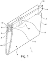
- FIG 1 is, insofar as shown in detail, a drawstring bag with 1, which consists of two opposite side parts 2, 3.
- the side parts 2, 3 have side edges 4, via which the two side parts 2, 3 are connected to one another.
- the side parts 2, 3 are folded over approximately in a U-shape, so that this cover and the connection of the two side parts 2, 3 via their side edges 4 result in a drawstring bag 1 which is initially closed on three sides.
- the drawstring bag 1 In the upper area when looking at the Figure 1 the drawstring bag 1 is initially open.
- loops 5, 6 are formed by the upper side edges of the side parts 2, 3.
- the drawstring 7 has a fixed drawstring end 8 with which it is fixedly arranged on the side edge 4. It extends along the loops 5 and 6 and comes out again at the side edge 4 opposite the fixed drawstring end 8 and forms an accessible free drawstring end 9 there.
- a recess 10 in the upper one can, but does not have to Edge region of the drawstring bag 1 may be provided. If this cutout 10 is present, the free end of the drawstring 9 (in particular its deflection region when it extends from the loop 5 in the direction of the loop 6) terminates there with the side edge 4. However, it is also conceivable for the free end of the drawstring 9 to protrude beyond the side edge 4.
- an additional aid for gripping can be arranged in this area of the free drawstring 9.
- a locking strip 11 Arranged on the drawstring 7 is a locking strip 11, which is either arranged within the loop 5 and is therefore not visible or not accessible. This is particularly the case if the locking strip 11 was fastened to the drawstring 7 before threading the drawstring 7 into the loop 5.
- the locking strip 11 is accessible from the outside or visible from the outside if either a recess has been provided in the loop 5 or if the locking strip 11 is formed by the side part 2 by punching out, perforating or the like. For example, when the drawstring 7 is in the hose 5 is located, a punching of the locking strip 11 take place after the side part 2 has been glued, welded or the like before the punching out.
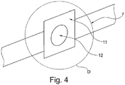
- edges 111, 112 lie outside the opening in the loop 5, which is formed by the edges 51, 52, it is necessary to pull the drawstring 7 with a slightly higher force in the region of its free drawstring end 9 in order to have the larger dimension Pull locking strips 11 into the receiving area, that is, into the loop 5. If the edges 51 and 111 on the one hand and 52 and 112 on the other hand form a continuous line, this is a sign that the locking strip 11 can, but need not, be formed from the side part 2. In this case too, it is conceivable that the edges 51/111 or 51/112 are aligned and the locking strip 11 is a separate component from the side part 2.
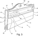
- Figure 3 shows as an alternative to that in Figure 1
- Drawstring bag 1 shown is a sinus bag with the same principle of the locking strip 11.
- the sinus bag according to Figure 3 differs from the drawstring bag according to Figure 1 in that it has a sinusoidal upper bag edge 13, in which a grip hole 14 is optionally incorporated, in particular punched out.
- a lower folded-over bag bottom 15 is present on the side opposite the opening side in the area of the sinusoidal upper bag edge 13, which has the advantage that when the two side parts 2, 3 move apart, the first folded-over bag bottom 15 offers a larger footprint after the sinus bag has been filled.
- the loop 5 or 6 is formed by using an additional support strip 16, which is placed with its side edges (fastening seam 17) on the surface of the side part 2 and connected non-detachably.
- the fastening seam 17 can be continuous, section-wise or punctiform and can be realized by an adhesive process, welding or the like.
- the drawstring 7 with its fixed drawstring end 8 in the area of one of the side edges 4 whereas the free drawstring end 9 is freely accessible on the side facing away from the fixed drawstring end 8.
- Figure 4 shows the detailed view D according to Figure 3 ,
- the drawstring 7 can be gripped at its free drawstring end 9 and can be moved out of the receiving area (formed by the loop 5, 6).
- the locking strip 11 comes to rest on the side edge 4 in the area of the free end of the drawstring 9. If the Locking strip comes to rest there or, if necessary, overlaps somewhat outside the side area of the bag in the area of the side edge 4 (while the fastening area 12 comes to rest on the side edge 4), the bag can no longer be opened or opened unintentionally, so that it is more advantageous Way remains permanently closed.
- the drawstring is firmly connected with its two ends on one side of the bag to the respective side part, while on the opposite side of the side part the drawstring is freely accessible and not with the each side part is connected to grasp and pull it out.
- the drawstring in its respective receiving area on or in the side part is firmly connected to the side part on both side edges of the respective side part and an opening, recess or the like in the area between these two fixed connections are provided in the respective side part, in which there is a free drawstring area, via which the drawstring can be gripped and pulled out of its receiving area.
- plastic material is particularly advantageous for realizing bags, drawstrings and locking strips, although other materials, such as paper or material combinations, are also conceivable.
Landscapes
- Engineering & Computer Science (AREA)
- Mechanical Engineering (AREA)
- Bag Frames (AREA)
- Purses, Travelling Bags, Baskets, Or Suitcases (AREA)
Description
- Die Erfindung betrifft einen Zugbandbeutel, gebildet aus zwei Seitenteilen, die an ihrer Seitenkante miteinander verbunden sind, wobei in einem öffnungsseitigen Bereich des Zugbandbeutels ein Aufnahmebereich für ein Zugband vorgesehen und in diesem Aufnahmebereich ein Zugband angeordnet ist, wobei das Zugband einerseits mit dem Zugbandbeutel verbunden und andererseits frei zugänglich ist, gemäß den Merkmalen des Oberbegriffes des Patentanspruches 1.
- Solche Zugbandbeutel, die zum Beispiel als Müllbeutel Verwendung finden, sind grundsätzlich bekannt. Aus der
US 4 813 794 A beispielsweise ist ein Zugbandbeutel mit den Merkmalen des Oberbegriffs des Anspruchs 1 bekannt. DieDE 93 07 723 U1 zeigt ebenfalls einen Zugbandbeutel mit einer Arretiervorrichtung. Die Zugbandbeutel werden auf geeignete Art und Weise derart hergestellt, dass drei Seiten des Zugbandbeutels geschlossen sind und somit ein Behältnis zur Aufnahme beliebiger Dinge bilden. Die vierte Seite ist offen gestaltet, um Dinge in den Zugbandbeutel einfüllen zu können. Nach dem Einfüllen kann in an sich bekannter Weise der Zugbandbeutel dadurch geschlossen werden, dass an dem Zugband gezo-gen wird, welches sich in einem Aufnahmebereich befindet. Durch dieses Ziehen an dem Zugband wird bewirkt, dass sich das Zugband aus dem Aufnahmebereich heraus bewegt und die bis hierhin vierte offene Seite des Zugbandbeutels zusammengezogen wird und sich dadurch der Zugbandbeutel verschließt. - Diese Art von Verschlüssen für Zugbandbeutel mittels eines Zugbandes haben sich grundsätzlich bewährt. Je nach Art der in den Zugbandbeutel eingeführten Dinge und auch abhängig von der Handhabung des Zugbandbeutels besteht jedoch die Möglichkeit, dass Bereiche des Zugbandes, die aus dem Aufnahmebereich herausbewegt worden sind, wieder in diesen Aufnahmebereich zurück gelangen. Dies bewirkt automatisch, dass sich der bisher verschlossene Zugbandbeutel zumindest teilweise, im negativen Fall aber auch vollständig öffnet und die bisher in den Zugbandbeutel einge-füllten Dinge bewusst oder unbewusst aus dem Zugbandbeutel gelangen können. Ins-besondere für den Fall, dass zum Beispiel Abfall in den Zugbandbeutel gefüllt worden ist, ist es von Nachteil, wenn der Zugbandbeutel sich wieder öffnen kann.
- Der Erfindung liegt daher die Aufgabe zugrunde, einen bekannten Zugbandbeutel da-hingehend zu verbessern, dass der einmal verschlossene Zugbandbeutel verschlossen bleibt. Es soll, wenn überhaupt, nur möglich sein, den Zugbandbeutel nochmals unter Aufbringung höherer Kräfte bzw. gegen einen Widerstand wieder zu öffnen.
- Diese Aufgabe ist durch die Merkmale des Patentanspruches 1 gelöst.
- Erfindungsgemäß ist vorgesehen, dass zwischen dem mit dem Zugbandbeutel verbundenen Bereich und dem frei zugänglichen Bereich des Zugbandes ein an dem Zugband angeordneter Arretierstreifen vorgesehen ist, der an einer Öffnungskante des Aufnahmebereiches für das Zugband zur Anlage kommt, wenn er diesen Aufnahmebereich verlassen hat. Wenn der Zugbandbeutel befüllt worden ist und verschlossen werden soll, wird in üblicher Form an dem Zugband gezogen, sodass dieses zu einem großen Teil den Aufnahmebereich, in dem es sich bisher befunden hat, verlässt. Dabei wird die Seitenkante der Öffnung des Zugbandbeutels längs des Zugbandes zusammengezogen, sodass sich dadurch diese Öffnung schließt. Gleichzeitig wird bewirkt, dass der Arretierstreifen ebenfalls aus dem Aufnahmebereich heraus bewegt wird, bis er sich nicht mehr in dem Aufnahmebereich befindet und von außen sichtbar ist. Damit ist verbunden, dass der Arretierstreifen an einer Öffnungskante des Aufnahmebereiches für das Zugband zur Anlage kommt, wenn er diesen Aufnahmebereich verlassen hat, wodurch in vorteilhafter Weise wirksam verhindert wird, dass sich die schon herausgezogenen Teile des Zugbandes wieder in den Aufnahmebe-reich zurückbewegen. Dies hat gleichzeitig zur Folge, dass die schon verschlossene Öffnung des Zugbandbetels verschlossen bleibt, weil es nicht möglich ist, dass sich das Zugband mittels des Arretierstreifens wieder in seinen Aufnahmebereich zurück bewegt. Der Arretierstreifen arretiert quasi nur noch einen geringen Teil des Zugbandes innerhalb des Aufnahmebereiches, während der größte Teil des Zugbandes sich außerhalb des Aufnahmebereiches befindet. Erst wenn zum Beispiel durch Aufbringung einer deutlich höheren Kraft (zur Überwindung des Arretierstreifens beim Zu-rückführen in den Aufnahmebereich) oder wenn der Arretierstreifen manuell in den Aufnahmebereich zurückgeführt wird, ist es möglich, den Zugbandbeutel zu öffnen, wobei dann dieser Öffnungsvorgang jedoch bewusst und nicht mehr wie bisher im Stand der Technik unbewusst ausgeführt werden muss.
- Die Realisierung des Arretierstreifens ist auf verschiedene Art und Weise möglich.
- In einer Ausgestaltung der Erfindung ist der Arretierstreifen auf das Zugband aufgeklebt. Alternativ oder ergänzend ist der Arretierstreifen mittels einer Schweißverbindung mit dem Zugband verbunden. Beide Möglichkeiten haben den Vorteil, dass verschiedene Arten und Weisen zur Verfügung stehen, um den Arretierstreifen an dem Zugband zu befestigen. So kann beispielsweise der Arretierstreifen schon an dem Zugband befestigt werden, bevor dieses in den Aufnahmebereich eingefädelt wird. Anstelle dessen ist es denkbar, den Arretierstreifen an dem Zugband zu befestigen, wenn das Zugband schon in den Aufnahmebereich eingefädelt worden ist.
- In Weiterbildung der Erfindung ist der Arretierstreifen ein von dem Seitenteil und dem Zugband separates Material, insbesondere eine Kunststoff-Folie, ein Papierstreifen oder dergleichen. Dies hat den Vorteil, dass geometrische Freiheiten hinsichtlich der Größe, der Ausdehnung, der Dicke und des Materials der Folie gegeben sind.
- In Weiterbildung der Erfindung ist der Arretierstreifen nicht als separates Teil von Zugbandbeutel oder Zugband gebildet, sondern wird von einem Seitenteil des Zugbandbeutels, dem sogenannten Muttermaterial, gebildet, vorzugsweise durch einen Ausstanzvorgang. Dies hat den Vorteil der be-sonders einfachen Herstellung, da der Zugbandbeutel zunächst mit dem Aufnahmebe-reich für das Zugband hergestellt und dann das Zugband dort in dem Aufnahmebe-reich angeordnet werden kann. Anschließend erfolgt ein Ausstanzen, ein Perforieren oder dergleichen des Arretierstreifens aus dem Seitenteil, wobei anschließend, gleich-zeitig oder vorher das Seitenteil mit dem Zugband dauerhaft verbunden wird. Dies kann wieder durch einen Klebevorgang, ein Schweißverfahren oder dergleichen erfolgen.
- Eine Verbindung zwischen Arretierstreifen und Seitenteil des Zugbandbeutels hat, genauso wie stegartige oder vergleichbare Verbindungen, den Vorteil, dass das Zugband zunächst definiert in dem Aufnahmebereich festgelegt ist. Erst nachdem der Zugbandbeutel befüllt worden ist, kann an dem frei zugänglichen Teil des Zugbandes gezogen werden, wobei dabei der Arretierstreifen von dem Seitenteil unter Aufbringung einer Mindestkraft gelöst wird. Anstelle dessen kann der Arretierstreifen auch vollständig abgetrennt sein von dem Seitenteil, auch wenn er von diesem gebildet ist.
- Für die Ausgestaltung des Aufnahmebereiches für das Zugband gibt es beispielsweise zwei Möglichkeiten.
- So ist zum einen in Weiterbildung der Erfindung der Aufnahmebereich für das Zugband als Schlaufe ausgebildet und von dem oberen Rand des Seitenteiles gebildet. Das bedeutet, dass der Aufnahmebereich für das Zugband im oberen Randbereich des Seitenteiles schlaufenförmig ist, wobei zur Bildung des Aufnahmebereiches für das Zugband nur der obere Rand des Seitenteiles verwendet wird. Hierdurch lässt sich die Handhabung weiterer Teile zur Bildung des Zugbandbeutels vermeiden, so-dass die Herstellung eines solchen Zugbandbeutels von besonderem Vorteil ist, weil optional auch in diesem Fall der Arretierstreifen in besonders vorteilhafter Weise von dem Seitenteil gebildet ist.
- Alternativ dazu ist in Weiterbildung der Erfindung vorgesehen, dass der Aufnahmebereich für das Zugband als Auflagestreifen ausgebildet ist, der entlang seiner Seitenkanten mit dem Seitenteil verbunden ist. Damit steht eine andere Realisierung für den Aufnahmebereich zur Verfügung, wobei ein streifenartiges Material verwendet wird, welches auf die Oberfläche des Seitenteiles aufgelegt und mit seinen Seitenkanten mit dem Seitenteil verbunden wird. Dadurch entsteht der Aufnahmebereich für das Zugband. Auch hier ist es denkbar, dass der Arretierstreifen losgelöst ist entweder von dem Seitenteil oder dem Auflagestreifen oder es ist denkbar, dass der Arretierstreifen wiederum gebildet ist von einem Teil des Seitenteiles oder des Auflagestreifens.
- In einer besonders vorteilhaften Ausgestaltung weist der Zugbandbeutel einen sinusförmigen oberen Beutelrand auf (sogenannter Sinusbeutel), wobei in dem sinusförmigen Beutelrand optional ein Griffloch vorgesehen ist. Das Griffloch kann zum Aufhängen oder Tragen des Beutels verwendet werden.
- Die Zugbandbeutel sind beispielsweise als Müllbeutel, einfache Flachbeutel, Brotbeutel, Gefrierbeutel oder ähnlich ausgeführt. Vorzugsweise bestehen sowohl der Beutel selber als auch das Zugband aus dem gleichen Material, insbesondere Kunststoff, wodurch in vorteilhafter Weise das Recycling verbessert wird. Unterschiedliche Kunststoffe sind auch denkbar. Ebenso ist es denkbar, das Material des Beutels und das Material des Zugbandes in gleicher oder unterschiedlicher Farbe auszuführen, wodurch ebenfalls Vorteile beim Recycling entstehen. So können unterschiedliche Farben von Beutel und Zugband auf unterschiedliche Materialen hinweisen. Umgekehrt liegen bei gleicher Farbe gleiche Materialien vor.
- Das Zugband kann bei gleichem oder unterschiedlichem Material wie der Beutel selber stärker (kann also höher Zugkräfte aushalten, zum Beispiel aufgrund größerer Dicke als die Dicke des Seitenteiles des Beutels) und/oder elastisch ausgeführt sein. Bei einem elastischen Zugband ist es möglich, beispielsweise beim Einsatz eines solchen als Müllbeutel ausgeführten Zugbandbeutels in einen starren Müllbehälter den oberen Rand des Müllbeutels um den oberen Rand des Müllbehälters zu legen und das elastische Zugband um diesen oberen Rand zu spannen.
- Während vorstehend davon ausgegangen worden ist, dass das Zugband eine längliche Kunststoff-Folie ist, kann es auch anderes gestaltet sein. So kommt beispielsweise eine Ausführung des Zugbandes als Kordel, Schnur oder dergleichen (jeweils aus Kunststoff, aus natürlichem Material oder einer Kombination davon) in Betracht. Der daran angebrachten Arretierstreifen muss sowohl bei dieser Ausführung als auch bei der Ausführung des Zugbandes aus Kunststoff nicht zwangsweise eine Streifenform aufweisen. Ist das Zugband länglich streifenförmig ausgebildet, ist der Arretierstreifen vorzugsweise quadratisch, rechteckig, rund oder oval gestaltet. Ist das Zugband als Kordel, Schnur oder dergleichen ausgebildet, ist der Arretierstreifen als Knoten ausgebildet oder als Clip, Verdickung oder dergleichen zum Beispiel mit der Schnur verbunden. Wichtig ist eine Formgebung, die es ermöglicht, dass dieser wie auch immer gestaltete Arretierstreifen, Knoten, Clip oder dergleichen an einer Öffnungskante des Aufnahmebereiches für das streifenförmige Zugband, die Kordel, die Schnur oder dergleichen zur Anlage kommt, wenn er diesen Aufnahmebereich verlassen hat.
- Im Folgenden wird die Erfindung an zwei Ausführungsbeispielen, auf die sie jedoch nicht beschränkt ist, näher erläutert.
- Es zeigen:
-
Figur 1 : Einen Zugbandbeutel mit einem arretierbarem Zugband, -
Figur 2 : ein Detail D gemäßFigur 1 , -
Figur 3 : einen Sinusbeutel mit arretierbarem Zugband, -
Figur 4 : ein Detail gemäßFigur 3 . - In
Figur 1 ist, soweit im Einzelnen dargestellt, ein Zugbandbeutel mit 1 bezeichnet, der aus zwei sich gegenüberliegenden Seitenteilen 2, 3 besteht. Die Seitenteile 2, 3 weisen Seitenkanten 4 auf, über die die beiden Seitenteile 2, 3 miteinander verbunden werden. Im bei Betrachtung derFigur 1 unteren Teil sind die Seitenteile 2, 3 in etwa U-förmig umgeschlagen, sodass durch diesen Umschlag und die Verbindung der bei-den Seitenteile 2, 3 über ihre Seitenkanten 4 ein zunächst dreiseitig verschlossener Zugbandbeutel 1 vorliegt. In dem oberen Bereich bei Betrachtung derFigur 1 ist der Zugbandbeutel 1 zunächst offen. In diesem oberen Kantenbereich des Zugbandbeutels 1 sind Schlaufen 5, 6 von den oberen Seitenrändern der Seitenteile 2, 3 gebildet. Durch den Umschlag der oberen Seitenränder der Seitenteile 2, 3 zur Bildung der Schlaufen 5, 6 wird ein Aufnahmebereich zu beiden Seiten für ein Zugband 7 geschaffen. Das Zugband 7 weist ein festes Zugbandende 8 auf, mit dem es fest an der Seitenkante 4 angeordnet ist. Es erstreckt sich längs der Schlaufe 5 und 6 und kommt an der dem festen Zugbandende 8 gegenüberliegenden Seitenkante 4 wieder heraus und bildet dort ein zugängliches freies Zugbandende 9. In dem Bereich des freien Zugbandendes 9 kann, muss aber nicht, eine Aussparung 10 in dem oberen Randbereich des Zugbandbeutels 1 vorgesehen sein. Ist diese Aussparung 10 vorhanden, schließt in vorteilhafter Weise das freie Zugbandende 9 (insbesondere sein Umlenkbereich bei der Erstreckung von der Schlaufe 5 in Richtung der Schlaufe 6) dort mit der Seitenkante 4 ab. Es ist allerdings auch denkbar, das freie Zugbandende 9 über die Seitenkante 4 hinausragen zu lassen. Außerdem kann in diesem Bereich des freien Zugbanden-des 9 ein zusätzliches Hilfsmittel zum Greifen (Fahne) angeordnet sein. - An dem Zugband 7 ist ein Arretierstreifen 11 angeordnet, der entweder innerhalb der Schlaufe 5 angeordnet und somit nicht sichtbar bzw. nicht zugänglich ist. Dies ist insbesondere dann der Fall, wenn der Arretierstreifen 11 vor dem Einfädeln des Zugbandes 7 in die Schlaufe 5 an dem Zugband 7 befestigt wurde. Alternativ dazu ist der Arretierstreifen 11 von außen zugänglich bzw. von außen sichtbar, wenn entweder in der Schlaufe 5 eine Aussparung vorgesehen wurde oder wenn der Arretierstreifen 11 von dem Seitenteil 2 durch Ausstanzen, Perforieren oder dergleichen gebildet wird. So kann beispielsweise dann, wenn das Zugband 7 sich in dem Schlauch 5 befindet, eine Ausstanzung des Arretierstreifens 11 erfolgen, nachdem vor dem Ausstanzen das Seitenteil 2 an dem Zugband 7 angeklebt, angeschweißt oder dergleichen worden ist.
- Diese Ausgestaltung des Details D ist sehr gut in
Figur 2 erkennbar. Dort ist gezeigt, dass das Zugband 7 mit dem Arretierstreifen 11 versehen worden ist, indem diese beiden Teile mittels eines Befestigungsbereiches 12 dauerhaft und unlösbar miteinander verbunden worden sind. Dies kann, wie schon ausgeführt, ein Klebevorgang, ein Schweißvorgang, eine Kombination davon oder dergleichen sein. Mit 51, 52 sind eine obere Kante und eine untere Kante der Schlaufe 5 bezeichnet. Analog dazu sind eine obere Kante 111 und eine untere Kante 112 des Arretierstreifens 11 näher bezeichnet. Liegen die beiden Kanten 111, 112 außerhalb der Öffnung in der Schlaufe 5, die durch die Kanten 51, 52 gebildet ist, ist es erforderlich, mit etwas höherer Kraft an dem Zugband 7 im Bereich seines freien Zugbandendes 9 zu ziehen, um den größer dimensionierten Arretierstreifen 11 in den Aufnahmebereich, das heißt in die Schlaufe 5 hinein, zu ziehen. Bilden die Kanten 51 und 111 einerseits und 52 und 112 andererseits eine durchgehende Linie, ist dies ein Zeichen dafür, dass der Arretierstreifen 11 aus dem Seitenteil 2 gebildet sein kann, aber nicht muss. Auch in diesem Fall ist es denkbar, dass die Kanten 51/111 bzw. 51/112 fluchtend sind und der Arretierstreifen 11 ein zu dem Seitenteil 2 separates Bauteil ist. -
Figur 3 zeigt als Alternative zu dem inFigur 1 dargestellten Zugbandbeutel 1 einen Sinusbeutel mit dem gleichen Prinzip des Arretierstreifens 11. - Der Sinusbeutel gemäß
Figur 3 unterscheidet sich von dem Zugbandbeutel gemäßFigur 1 dadurch, dass er einen sinusförmigen oberen Beutelrand 13 aufweist, in dem optional ein Griffloch 14 eingearbeitet, insbesondere ausgestanzt ist. - Der Öffnungsseite im Bereich des sinusförmigen oberen Beutelrandes 13 gegenüber-liegenden Seite ist ein unterer umgeschlagener Beutelboden 15 vorhanden, der den Vorteil hat, dass mit Auseinanderbewegung der beiden Seitenteile 2, 3 der zunächst umgeschlagene Beutelboden 15 nach der Befüllung des Sinusbeutels eine größere Aufstellfläche bietet.
- Bei dem Ausführungsbeispiel gemäß
Figur 3 ist (alternativ zu dem Zugbandbeutel gemäß des Ausführungsbeispiels inFigur 1 ) die Schlaufe 5 bzw. 6 dadurch gebildet, dass ein zusätzlicher Auflagestreifen 16 verwendet wird, der mit seinen Seitenkanten (Befestigungsnaht 17) auf der Oberfläche des Seitenteils 2 auf-gelegt und unlösbar verbunden wird. Die Befestigungsnaht 17 kann durchgehend, abschnittsweise oder punktförmig ausgebildet sein und durch einen Klebevorgang, ein Verschweißen oder dergleichen realisiert werden. Auch hier ist, genauso wie bei dem Ausführungsbeispiel inFigur 1 , das Zugband 7 mit seinem festen Zugbandende 8 im Bereich einer der Seitenkanten 4 fest angeschlagen, wohingegen auf der dem festen Zugbandende 8 abgewandten Seite das freie Zugbandende 9 frei zugänglich ist.Figur 4 zeigt die Detailansicht D gemäßFigur 3 . - Für beide Ausführungsbeispiele gilt, dass nach der Befüllung des Beutels das Zugband 7 an seinem freien Zugbandende 9 gegriffen werden kann und aus dem Aufnahmebereich (gebildet durch die Schlaufe 5, 6) herausbewegt werden kann. Durch die Herausbewegung des größten Teiles des Zugbandes 7 aus seinem Aufnahmebe-reich, ein einschließlich des Arretierstreifens 11, wird nicht nur der Beutel verschlossen, sondern der Arretierstreifen 11 kommt zur Anlage an der Seitenkante 4 im Be-reich des freien Zugbandendes 9. Wenn der Arretierstreifen dort zur Anlage kommt oder gegebenenfalls außerhalb den Seitenbereich des Beutels im Bereich der Seiten-kante 4 etwas überlappt (während der Befestigungsbereich 12 an der Seitenkante 4 zur Anlage kommt) kann der Beutel nicht mehr ungewollt geöffnet werden oder sich öffnen, sodass er in vorteilhafter Weise dauerhaft geschlossen bleibt. Sollte es den-noch gewünscht sein, dass der Beutel noch einmal geöffnet wird, kann dies dadurch erfolgen, dass der obere Bereich des Beutels im Öffnungsbereich gegriffen wird und die beiden Seitenteile, die dort nach dem Verschließen zusammengezogen wurden, auseinander bewegt werden. Hierfür ist eine erhöhte Kraft erforderlich, um den Arretierstreifen 11 der bisher zur Anlage kam an der Seitenkante 4 im Bereich des freien Zugbandendes 9, wieder in den Aufnahmebereich zurückzubewegen. Je nach Ausgestaltung des Arretierstreifens 11 sind mehr oder weniger große Kräfte erforderlich, um den Beutel erneut zu öffnen. Das vorstehend mittels des Arretierstreifens 11 beschriebene arretierbare Zugband 7 ist bei Zugband- und Sinusbeuteln (wie dargestellt) anwendbar, aber auch bei anderen dafür geeigneten Beuteln einsetzbar.
- In den beiden vorstehend beschriebenen Ausführungsbeispielen ist gezeigt und beschrieben, dass das Zugband mit seinen beiden Enden auf der einen Seite des Beutels fest mit dem jeweiligen Seitenteil verbunden ist, während auf der gegenüberliegenden Seite des Seitenteiles das Zugband ein Stück weit frei zugänglich und nicht mit dem jeweiligen Seitenteil verbunden ist, um es ergreifen und herausziehen zu können.
- Alternativ dazu kann auch ohne Beschränkung auf eines der gezeigten Ausführungsbeispiele daran gedacht werden, dass das Zugband in seinem jeweiligen Aufnahmebereich an bzw. in dem Seitenteil an beiden Seitenkanten des jeweiligen Seitenteiles fest mit dem Seitenteil verbunden und eine Öffnung, Aussparung oder dergleichen in dem Bereich zwischen diesen beiden festen Verbindungen in dem jeweiligen Seitenteil vorgesehen ist, in denen sich ein freier Zugbandbereich befindet, über den das Zugband ergriffen und aus seinem Aufnahmebereich herausgezogen werden kann.
- Beide vorstehend beschriebenen Varianten, genauso wie analoge Abwandlungen, bewirken, dass das Zugband an einem frei zugänglichen Bereich (entweder das Zugbandende oder ein Bereich im Laufe der Erstreckung des Zugbandes) ergriffen und aus seinem Aufnahmebereich herausgezogen werden kann, wobei dadurch, wenn das Zugband zu einem größeren Teil aus dem Aufnahmebereich herausgezogen worden ist, nicht nur der Beutel verschlossen wird, sondern auch der herausgezogene Arretierstreifen an einer Öffnungskante des Aufnahmebereiches für das Zugband zur Anlage kommt, wenn er diesen Aufnahmebereich verlassen hat, wodurch der Beutel dauerhaft (und ggfs. wieder zu öffnen) verschlossen ist.
- Von besonderem Vorteil ist der Einsatz von Kunststoffmaterial zu Realisierung von Beutel, Zugband und Arretierstreifen, wobei aber auch andere Materialien, wie zum Beispiel Papier oder Materialkombinationen denkbar sind.
-
- 1.
- Zugbandbeutel
- 2.
- Seitenteil
- 3.
- Seitenteil
- 4.
- Seitenkante
- 5.
- Schlaufe
- 51.
- Obere Kante
- 52.
- Untere Kante
- 6.
- Schlaufe
- 7.
- Zugband
- 8.
- Festes Zugbandende
- 9.
- Freies Zugbandende
- 10.
- Aussparung
- 11.
- Arretierstreifen
- 111.
- Obere Kante
- 112.
- Untere Kante
- 12.
- Befestigungsbereich
- 13.
- Sinusförmiger oberer Beutelrand
- 14.
- Griffloch
- 15.
- Unterer umgeschlagener Beutelboden
- 16.
- Auflagestreifen
- 17.
- Befestigungsnaht
Claims (10)
- Zugbandbeutel (1), gebildet aus zwei Seitenteilen (2, 3), die an ihrer Seitenkante (4) miteinander verbunden sind, wobei in einem öffnungsseitigen Bereich des Zugbandbeutels (1) ein Aufnahmebereich für ein Zugband (7) vorgesehen und in diesem Aufnahmebereich ein Zugband (7) angeordnet ist, wobei das Zugband (7) einerseits mit dem Zugbandbeutel (1) verbunden und andererseits frei zugänglich ist, dadurch gekennzeichnet, dass zwischen dem mit dem Zugbandbeutel (1) verbundenen Bereich und dem frei zugänglichen Bereich des Zugbandes (7) ein an dem Zugband (7) angeordneter Arretierstreifen (11) vorgesehen ist, der an einer Öffnungskante des Aufnahmebereiches für das Zugband (7) zur Anlage kommt, wenn er diesen Aufnahmebereich verlassen hat.
- Zugbandbeutel (1) nach Anspruch 1, dadurch gekennzeichnet, dass der Arretierstreifen (11) auf das Zugband (7) aufgeklebt ist.
- Zugbandbeutel (1) nach Anspruch 1, dadurch gekennzeichnet, dass der Arretierstreifen (11) mittels einer Schweißverbindung mit dem Zugband (7) verbunden ist.
- Zugbandbeutel (1) nach Anspruch 1, 2 oder 3, dadurch gekennzeichnet, dass der Arretierstreifen (11) ein von dem Seitenteil (2) und dem Zugband (7) separates Stück Material, insbesondere eine Kunststoff-Folie, ein Papierstreifen oder dergleichen, ist.
- Zugbandbeutel (1) nach Anspruch 1, 2 oder 3, dadurch gekennzeichnet, dass der Arretierstreifen (11) von dem Seitenteil (2) des Zugbandbeutels (1) gebildet ist.
- Zugbandbeutel (1) nach Anspruch 5, dadurch gekennzeichnet, dass der Arretierstreifen (11) lösbar mit dem Seitenteil (2) verbunden ist.
- Zugbandbeutel (1) nach Anspruch 6, dadurch gekennzeichnet, dass der Arretierstreifen (11) über eine Perforation mit dem Seitenteil (2) verbunden ist.
- Zugbandbeutel (1) nach einem der vorhergehenden Ansprüche, dadurch gekennzeichnet, dass der Aufnahmebereich für das Zugband (7) als Schlaufe (5, 6) ausgebildet und von dem oberen Rand des Seitenteiles (2, 3) gebildet ist.
- Zugbandbeutel (1) nach einem der vorhergehenden Ansprüche, dadurch gekennzeichnet, dass der Aufnahmebereich für das Zugband (7) als Auflagestreifen (16) ausgebildet ist, der entlang seiner Seitenkanten mit dem Seitenteil (2) verbunden ist.
- Zugbandbeutel (1) nach einem der vorhergehenden Ansprüche, dadurch gekennzeichnet, dass der Zugbandbeutel (1) einen sinusförmigen oberen Beutelrand (13) aufweist.
Priority Applications (1)
| Application Number | Priority Date | Filing Date | Title |
|---|---|---|---|
| PL16730373T PL3310680T3 (pl) | 2015-06-18 | 2016-06-17 | Worek z taśmą ściągającą z blokowaną taśmą ściągającą |
Applications Claiming Priority (2)
| Application Number | Priority Date | Filing Date | Title |
|---|---|---|---|
| DE102015109768 | 2015-06-18 | ||
| PCT/EP2016/064019 WO2016202988A1 (de) | 2015-06-18 | 2016-06-17 | Zugbandbeutel mit arretierbarem zugband |
Publications (2)
| Publication Number | Publication Date |
|---|---|
| EP3310680A1 EP3310680A1 (de) | 2018-04-25 |
| EP3310680B1 true EP3310680B1 (de) | 2019-12-18 |
Family
ID=56137335
Family Applications (1)
| Application Number | Title | Priority Date | Filing Date |
|---|---|---|---|
| EP16730373.4A Active EP3310680B1 (de) | 2015-06-18 | 2016-06-17 | Zugbandbeutel mit arretierbarem zugband |
Country Status (9)
| Country | Link |
|---|---|
| US (1) | US10407218B2 (de) |
| EP (1) | EP3310680B1 (de) |
| CN (1) | CN107820480B (de) |
| CA (1) | CA2990508C (de) |
| DE (1) | DE102016111114A1 (de) |
| ES (1) | ES2769254T3 (de) |
| PL (1) | PL3310680T3 (de) |
| RU (1) | RU2722430C2 (de) |
| WO (1) | WO2016202988A1 (de) |
Families Citing this family (4)
| Publication number | Priority date | Publication date | Assignee | Title |
|---|---|---|---|---|
| US12459714B2 (en) | 2019-03-28 | 2025-11-04 | The Glad Products Company | Multi-film thermoplastic bags with zones of contact areas having variable lamination |
| US11814225B2 (en) | 2019-03-28 | 2023-11-14 | The Glad Products Company | Multi-film thermoplastic structures having visually-distinct contact areas arranged in text and methods of making the same |
| CA3134701A1 (en) | 2019-03-28 | 2020-10-01 | The Glad Products Company | Multi-film thermoplastic structures and bags having visually-distinct contact areas and methods of making the same |
| CN110525830A (zh) * | 2019-09-25 | 2019-12-03 | 温州易的产品设计有限公司 | 一种折叠易展开垃圾袋及其制造工艺 |
Family Cites Families (15)
| Publication number | Priority date | Publication date | Assignee | Title |
|---|---|---|---|---|
| US4813794A (en) * | 1988-05-19 | 1989-03-21 | Mobil Oil Corporation | Thermoplastic draw tape bag with tacky tape |
| DE9307723U1 (de) * | 1993-05-21 | 1993-07-22 | VP-Schickedanz AG, 90489 Nürnberg | Folienschlauchbeutel, insbesondere zur Aufbewahrung von Hygieneartikeln |
| ES2119045T3 (es) * | 1994-09-08 | 1998-10-01 | Lemo Maschb Gmbh | Bolsa de folio termoplastico. |
| US5839631A (en) * | 1997-05-14 | 1998-11-24 | Hebert; Luc | Cloth golf ball holder |
| DE10218720B3 (de) * | 2002-04-26 | 2004-02-05 | Lemo Maschinenbau Gmbh | Zugbandbeutel mit Klebestreifen |
| KR200425910Y1 (ko) * | 2006-05-08 | 2006-09-08 | 김정모 | 휴지통 |
| JP5016436B2 (ja) * | 2007-10-05 | 2012-09-05 | ユニ・チャーム株式会社 | 包装体 |
| US8118489B2 (en) * | 2009-09-23 | 2012-02-21 | The Glad Products Company | Bag |
| CN201703674U (zh) * | 2009-09-29 | 2011-01-12 | 营口东盛实业有限公司 | 携带方便的特型袋 |
| US20110243482A1 (en) * | 2010-03-31 | 2011-10-06 | Kristy First | Gift Wrap Bag |
| US8790009B2 (en) | 2010-07-06 | 2014-07-29 | B3 Plastics, Llc | Bag with secondary handle |
| WO2013006870A1 (en) * | 2011-07-05 | 2013-01-10 | Sale Mark D | Improved bag with secondary handle |
| US20140241847A1 (en) * | 2013-02-25 | 2014-08-28 | Philip R. Short | Produce package and method for displaying produce for sale |
| NO339738B1 (no) * | 2015-04-15 | 2017-01-30 | Norgesposen As | Pose |
| US20170158380A1 (en) * | 2015-12-02 | 2017-06-08 | Poly-America, L.P. | Reclosable bag and method to make same |
-
2016
- 2016-06-17 ES ES16730373T patent/ES2769254T3/es active Active
- 2016-06-17 EP EP16730373.4A patent/EP3310680B1/de active Active
- 2016-06-17 CA CA2990508A patent/CA2990508C/en active Active
- 2016-06-17 WO PCT/EP2016/064019 patent/WO2016202988A1/de not_active Ceased
- 2016-06-17 PL PL16730373T patent/PL3310680T3/pl unknown
- 2016-06-17 RU RU2018101179A patent/RU2722430C2/ru active
- 2016-06-17 CN CN201680035621.0A patent/CN107820480B/zh active Active
- 2016-06-17 DE DE102016111114.7A patent/DE102016111114A1/de not_active Withdrawn
- 2016-06-17 US US15/572,912 patent/US10407218B2/en active Active
Non-Patent Citations (1)
| Title |
|---|
| None * |
Also Published As
| Publication number | Publication date |
|---|---|
| CA2990508C (en) | 2023-04-11 |
| US20180282025A1 (en) | 2018-10-04 |
| DE102016111114A1 (de) | 2016-12-22 |
| RU2018101179A (ru) | 2019-07-22 |
| EP3310680A1 (de) | 2018-04-25 |
| US10407218B2 (en) | 2019-09-10 |
| WO2016202988A1 (de) | 2016-12-22 |
| PL3310680T3 (pl) | 2020-06-15 |
| CN107820480A (zh) | 2018-03-20 |
| CN107820480B (zh) | 2020-07-31 |
| CA2990508A1 (en) | 2016-12-22 |
| ES2769254T3 (es) | 2020-06-25 |
| RU2018101179A3 (de) | 2019-07-30 |
| RU2722430C2 (ru) | 2020-05-29 |
Similar Documents
| Publication | Publication Date | Title |
|---|---|---|
| DE102009007985B4 (de) | Wiederverschließbare Papiertragetasche/Versandtragetasche | |
| DE102016111114A1 (de) | Zugbandbeutel mit arretierbarem Zugband | |
| EP2050689A1 (de) | Verpackungsbeutel | |
| DE69004976T2 (de) | Behälter zur Aufnahme und Abgabe schnurförmiger Gegenstände. | |
| DE102009042031A1 (de) | Beutel | |
| EP0183064B1 (de) | Flachbeutel | |
| EP0684922B1 (de) | Folienbeutel für hygieneartikel | |
| EP2743198A1 (de) | Versandtasche mit Aufreißstreifen | |
| DE102007037397A1 (de) | Beutel | |
| DE102016116639A1 (de) | Zugbandbeutel ohne Saumlängsnaht | |
| DE2742382A1 (de) | Seitenfalten-kunststoffbeutel, insbesondere muellbeutel | |
| DE3907291C2 (de) | ||
| DE4214649B4 (de) | Folienbeutel für Hygieneartikel | |
| DE10138612A1 (de) | Beutel mit Magnetverschluß | |
| EP1671892B1 (de) | Beutel | |
| DE732695C (de) | Verschluss- und Klemmvorrichtung zum Verschliessen und Tragen von zum Befoerdern von Waren dienenden Taschen, Saecken u. dgl. | |
| EP3954624B1 (de) | Verpackungsbeutel sowie verfahren zur herstellung eines verpackungsbeutels | |
| DE8507919U1 (de) | Offener Verpackungsbeutel aus Kunststoff | |
| DE4211349C2 (de) | ||
| DE202009002028U1 (de) | Folienbeutel | |
| DE1291280B (de) | Abreissblock als Vorratsblock fuer Kunststoff-Warenbeutel | |
| DE3816565C2 (de) | Verschluß für eine Tüte | |
| DE2247657A1 (de) | Tragtasche | |
| DE4135960A1 (de) | Verfahren zur herstellung eines sacks oder beutels mit in gefuelltem zustand rechteckigem boden und mit einem griffteil und nach diesem verfahren hergestellter sack oder beutel | |
| DE2734657A1 (de) | Aufhaengeverpackung |
Legal Events
| Date | Code | Title | Description |
|---|---|---|---|
| STAA | Information on the status of an ep patent application or granted ep patent |
Free format text: STATUS: THE INTERNATIONAL PUBLICATION HAS BEEN MADE |
|
| PUAI | Public reference made under article 153(3) epc to a published international application that has entered the european phase |
Free format text: ORIGINAL CODE: 0009012 |
|
| STAA | Information on the status of an ep patent application or granted ep patent |
Free format text: STATUS: REQUEST FOR EXAMINATION WAS MADE |
|
| 17P | Request for examination filed |
Effective date: 20171110 |
|
| AK | Designated contracting states |
Kind code of ref document: A1 Designated state(s): AL AT BE BG CH CY CZ DE DK EE ES FI FR GB GR HR HU IE IS IT LI LT LU LV MC MK MT NL NO PL PT RO RS SE SI SK SM TR |
|
| AX | Request for extension of the european patent |
Extension state: BA ME |
|
| DAV | Request for validation of the european patent (deleted) | ||
| DAX | Request for extension of the european patent (deleted) | ||
| GRAP | Despatch of communication of intention to grant a patent |
Free format text: ORIGINAL CODE: EPIDOSNIGR1 |
|
| STAA | Information on the status of an ep patent application or granted ep patent |
Free format text: STATUS: GRANT OF PATENT IS INTENDED |
|
| INTG | Intention to grant announced |
Effective date: 20190208 |
|
| GRAJ | Information related to disapproval of communication of intention to grant by the applicant or resumption of examination proceedings by the epo deleted |
Free format text: ORIGINAL CODE: EPIDOSDIGR1 |
|
| STAA | Information on the status of an ep patent application or granted ep patent |
Free format text: STATUS: REQUEST FOR EXAMINATION WAS MADE |
|
| INTC | Intention to grant announced (deleted) | ||
| GRAP | Despatch of communication of intention to grant a patent |
Free format text: ORIGINAL CODE: EPIDOSNIGR1 |
|
| STAA | Information on the status of an ep patent application or granted ep patent |
Free format text: STATUS: GRANT OF PATENT IS INTENDED |
|
| INTG | Intention to grant announced |
Effective date: 20190809 |
|
| GRAS | Grant fee paid |
Free format text: ORIGINAL CODE: EPIDOSNIGR3 |
|
| GRAA | (expected) grant |
Free format text: ORIGINAL CODE: 0009210 |
|
| STAA | Information on the status of an ep patent application or granted ep patent |
Free format text: STATUS: THE PATENT HAS BEEN GRANTED |
|
| AK | Designated contracting states |
Kind code of ref document: B1 Designated state(s): AL AT BE BG CH CY CZ DE DK EE ES FI FR GB GR HR HU IE IS IT LI LT LU LV MC MK MT NL NO PL PT RO RS SE SI SK SM TR |
|
| REG | Reference to a national code |
Ref country code: CH Ref legal event code: EP |
|
| REG | Reference to a national code |
Ref country code: IE Ref legal event code: FG4D Free format text: LANGUAGE OF EP DOCUMENT: GERMAN |
|
| REG | Reference to a national code |
Ref country code: DE Ref legal event code: R096 Ref document number: 502016008065 Country of ref document: DE |
|
| REG | Reference to a national code |
Ref country code: AT Ref legal event code: REF Ref document number: 1214355 Country of ref document: AT Kind code of ref document: T Effective date: 20200115 |
|
| REG | Reference to a national code |
Ref country code: SE Ref legal event code: TRGR |
|
| REG | Reference to a national code |
Ref country code: NL Ref legal event code: MP Effective date: 20191218 |
|
| PG25 | Lapsed in a contracting state [announced via postgrant information from national office to epo] |
Ref country code: GR Free format text: LAPSE BECAUSE OF FAILURE TO SUBMIT A TRANSLATION OF THE DESCRIPTION OR TO PAY THE FEE WITHIN THE PRESCRIBED TIME-LIMIT Effective date: 20200319 Ref country code: LT Free format text: LAPSE BECAUSE OF FAILURE TO SUBMIT A TRANSLATION OF THE DESCRIPTION OR TO PAY THE FEE WITHIN THE PRESCRIBED TIME-LIMIT Effective date: 20191218 Ref country code: LV Free format text: LAPSE BECAUSE OF FAILURE TO SUBMIT A TRANSLATION OF THE DESCRIPTION OR TO PAY THE FEE WITHIN THE PRESCRIBED TIME-LIMIT Effective date: 20191218 Ref country code: FI Free format text: LAPSE BECAUSE OF FAILURE TO SUBMIT A TRANSLATION OF THE DESCRIPTION OR TO PAY THE FEE WITHIN THE PRESCRIBED TIME-LIMIT Effective date: 20191218 Ref country code: BG Free format text: LAPSE BECAUSE OF FAILURE TO SUBMIT A TRANSLATION OF THE DESCRIPTION OR TO PAY THE FEE WITHIN THE PRESCRIBED TIME-LIMIT Effective date: 20200318 |
|
| REG | Reference to a national code |
Ref country code: LT Ref legal event code: MG4D Ref country code: NO Ref legal event code: T2 Effective date: 20191218 |
|
| PG25 | Lapsed in a contracting state [announced via postgrant information from national office to epo] |
Ref country code: HR Free format text: LAPSE BECAUSE OF FAILURE TO SUBMIT A TRANSLATION OF THE DESCRIPTION OR TO PAY THE FEE WITHIN THE PRESCRIBED TIME-LIMIT Effective date: 20191218 Ref country code: RS Free format text: LAPSE BECAUSE OF FAILURE TO SUBMIT A TRANSLATION OF THE DESCRIPTION OR TO PAY THE FEE WITHIN THE PRESCRIBED TIME-LIMIT Effective date: 20191218 |
|
| REG | Reference to a national code |
Ref country code: ES Ref legal event code: FG2A Ref document number: 2769254 Country of ref document: ES Kind code of ref document: T3 Effective date: 20200625 |
|
| PG25 | Lapsed in a contracting state [announced via postgrant information from national office to epo] |
Ref country code: AL Free format text: LAPSE BECAUSE OF FAILURE TO SUBMIT A TRANSLATION OF THE DESCRIPTION OR TO PAY THE FEE WITHIN THE PRESCRIBED TIME-LIMIT Effective date: 20191218 |
|
| PG25 | Lapsed in a contracting state [announced via postgrant information from national office to epo] |
Ref country code: NL Free format text: LAPSE BECAUSE OF FAILURE TO SUBMIT A TRANSLATION OF THE DESCRIPTION OR TO PAY THE FEE WITHIN THE PRESCRIBED TIME-LIMIT Effective date: 20191218 Ref country code: EE Free format text: LAPSE BECAUSE OF FAILURE TO SUBMIT A TRANSLATION OF THE DESCRIPTION OR TO PAY THE FEE WITHIN THE PRESCRIBED TIME-LIMIT Effective date: 20191218 Ref country code: CZ Free format text: LAPSE BECAUSE OF FAILURE TO SUBMIT A TRANSLATION OF THE DESCRIPTION OR TO PAY THE FEE WITHIN THE PRESCRIBED TIME-LIMIT Effective date: 20191218 Ref country code: PT Free format text: LAPSE BECAUSE OF FAILURE TO SUBMIT A TRANSLATION OF THE DESCRIPTION OR TO PAY THE FEE WITHIN THE PRESCRIBED TIME-LIMIT Effective date: 20200513 Ref country code: RO Free format text: LAPSE BECAUSE OF FAILURE TO SUBMIT A TRANSLATION OF THE DESCRIPTION OR TO PAY THE FEE WITHIN THE PRESCRIBED TIME-LIMIT Effective date: 20191218 |
|
| PG25 | Lapsed in a contracting state [announced via postgrant information from national office to epo] |
Ref country code: SK Free format text: LAPSE BECAUSE OF FAILURE TO SUBMIT A TRANSLATION OF THE DESCRIPTION OR TO PAY THE FEE WITHIN THE PRESCRIBED TIME-LIMIT Effective date: 20191218 Ref country code: IS Free format text: LAPSE BECAUSE OF FAILURE TO SUBMIT A TRANSLATION OF THE DESCRIPTION OR TO PAY THE FEE WITHIN THE PRESCRIBED TIME-LIMIT Effective date: 20200418 Ref country code: SM Free format text: LAPSE BECAUSE OF FAILURE TO SUBMIT A TRANSLATION OF THE DESCRIPTION OR TO PAY THE FEE WITHIN THE PRESCRIBED TIME-LIMIT Effective date: 20191218 |
|
| REG | Reference to a national code |
Ref country code: DE Ref legal event code: R097 Ref document number: 502016008065 Country of ref document: DE |
|
| PLBE | No opposition filed within time limit |
Free format text: ORIGINAL CODE: 0009261 |
|
| STAA | Information on the status of an ep patent application or granted ep patent |
Free format text: STATUS: NO OPPOSITION FILED WITHIN TIME LIMIT |
|
| PG25 | Lapsed in a contracting state [announced via postgrant information from national office to epo] |
Ref country code: DK Free format text: LAPSE BECAUSE OF FAILURE TO SUBMIT A TRANSLATION OF THE DESCRIPTION OR TO PAY THE FEE WITHIN THE PRESCRIBED TIME-LIMIT Effective date: 20191218 |
|
| 26N | No opposition filed |
Effective date: 20200921 |
|
| PG25 | Lapsed in a contracting state [announced via postgrant information from national office to epo] |
Ref country code: SI Free format text: LAPSE BECAUSE OF FAILURE TO SUBMIT A TRANSLATION OF THE DESCRIPTION OR TO PAY THE FEE WITHIN THE PRESCRIBED TIME-LIMIT Effective date: 20191218 |
|
| PG25 | Lapsed in a contracting state [announced via postgrant information from national office to epo] |
Ref country code: MC Free format text: LAPSE BECAUSE OF FAILURE TO SUBMIT A TRANSLATION OF THE DESCRIPTION OR TO PAY THE FEE WITHIN THE PRESCRIBED TIME-LIMIT Effective date: 20191218 |
|
| REG | Reference to a national code |
Ref country code: CH Ref legal event code: PL |
|
| GBPC | Gb: european patent ceased through non-payment of renewal fee |
Effective date: 20200617 |
|
| PG25 | Lapsed in a contracting state [announced via postgrant information from national office to epo] |
Ref country code: LU Free format text: LAPSE BECAUSE OF NON-PAYMENT OF DUE FEES Effective date: 20200617 |
|
| PG25 | Lapsed in a contracting state [announced via postgrant information from national office to epo] |
Ref country code: LI Free format text: LAPSE BECAUSE OF NON-PAYMENT OF DUE FEES Effective date: 20200630 Ref country code: CH Free format text: LAPSE BECAUSE OF NON-PAYMENT OF DUE FEES Effective date: 20200630 Ref country code: FR Free format text: LAPSE BECAUSE OF NON-PAYMENT OF DUE FEES Effective date: 20200630 Ref country code: GB Free format text: LAPSE BECAUSE OF NON-PAYMENT OF DUE FEES Effective date: 20200617 Ref country code: IE Free format text: LAPSE BECAUSE OF NON-PAYMENT OF DUE FEES Effective date: 20200617 |
|
| PG25 | Lapsed in a contracting state [announced via postgrant information from national office to epo] |
Ref country code: MT Free format text: LAPSE BECAUSE OF FAILURE TO SUBMIT A TRANSLATION OF THE DESCRIPTION OR TO PAY THE FEE WITHIN THE PRESCRIBED TIME-LIMIT Effective date: 20191218 Ref country code: CY Free format text: LAPSE BECAUSE OF FAILURE TO SUBMIT A TRANSLATION OF THE DESCRIPTION OR TO PAY THE FEE WITHIN THE PRESCRIBED TIME-LIMIT Effective date: 20191218 |
|
| PG25 | Lapsed in a contracting state [announced via postgrant information from national office to epo] |
Ref country code: MK Free format text: LAPSE BECAUSE OF FAILURE TO SUBMIT A TRANSLATION OF THE DESCRIPTION OR TO PAY THE FEE WITHIN THE PRESCRIBED TIME-LIMIT Effective date: 20191218 |
|
| REG | Reference to a national code |
Ref country code: AT Ref legal event code: MM01 Ref document number: 1214355 Country of ref document: AT Kind code of ref document: T Effective date: 20210617 |
|
| PG25 | Lapsed in a contracting state [announced via postgrant information from national office to epo] |
Ref country code: AT Free format text: LAPSE BECAUSE OF NON-PAYMENT OF DUE FEES Effective date: 20210617 |
|
| PGFP | Annual fee paid to national office [announced via postgrant information from national office to epo] |
Ref country code: PL Payment date: 20250606 Year of fee payment: 10 Ref country code: DE Payment date: 20250618 Year of fee payment: 10 |
|
| PGFP | Annual fee paid to national office [announced via postgrant information from national office to epo] |
Ref country code: NO Payment date: 20250624 Year of fee payment: 10 |
|
| PGFP | Annual fee paid to national office [announced via postgrant information from national office to epo] |
Ref country code: BE Payment date: 20250618 Year of fee payment: 10 |
|
| PGFP | Annual fee paid to national office [announced via postgrant information from national office to epo] |
Ref country code: TR Payment date: 20250611 Year of fee payment: 10 |
|
| PGFP | Annual fee paid to national office [announced via postgrant information from national office to epo] |
Ref country code: SE Payment date: 20250618 Year of fee payment: 10 |
|
| PGFP | Annual fee paid to national office [announced via postgrant information from national office to epo] |
Ref country code: ES Payment date: 20250728 Year of fee payment: 10 |
|
| PGFP | Annual fee paid to national office [announced via postgrant information from national office to epo] |
Ref country code: IT Payment date: 20250624 Year of fee payment: 10 |
|
| REG | Reference to a national code |
Ref country code: DE Ref legal event code: R082 Ref document number: 502016008065 Country of ref document: DE |