EP3310723B1 - Transportsystem zum glühen von glasbehältern - Google Patents
Transportsystem zum glühen von glasbehältern Download PDFInfo
- Publication number
- EP3310723B1 EP3310723B1 EP16729888.4A EP16729888A EP3310723B1 EP 3310723 B1 EP3310723 B1 EP 3310723B1 EP 16729888 A EP16729888 A EP 16729888A EP 3310723 B1 EP3310723 B1 EP 3310723B1
- Authority
- EP
- European Patent Office
- Prior art keywords
- transportation system
- lath
- inserts
- glass container
- barrel
- Prior art date
- Legal status (The legal status is an assumption and is not a legal conclusion. Google has not performed a legal analysis and makes no representation as to the accuracy of the status listed.)
- Active
Links
Images




Classifications
-
- C—CHEMISTRY; METALLURGY
- C03—GLASS; MINERAL OR SLAG WOOL
- C03B—MANUFACTURE, SHAPING, OR SUPPLEMENTARY PROCESSES
- C03B35/00—Transporting of glass products during their manufacture, e.g. hot glass lenses, prisms
- C03B35/04—Transporting of hot hollow or semi-hollow glass products
- C03B35/06—Feeding of hot hollow glass products into annealing or heating kilns
- C03B35/062—Feeding of hot hollow glass products into annealing or heating kilns using conveyors, e.g. chain- or roller conveyors, dead-plates
-
- C—CHEMISTRY; METALLURGY
- C03—GLASS; MINERAL OR SLAG WOOL
- C03B—MANUFACTURE, SHAPING, OR SUPPLEMENTARY PROCESSES
- C03B25/00—Annealing glass products
- C03B25/04—Annealing glass products in a continuous way
- C03B25/06—Annealing glass products in a continuous way with horizontal displacement of the glass products
-
- C—CHEMISTRY; METALLURGY
- C03—GLASS; MINERAL OR SLAG WOOL
- C03B—MANUFACTURE, SHAPING, OR SUPPLEMENTARY PROCESSES
- C03B35/00—Transporting of glass products during their manufacture, e.g. hot glass lenses, prisms
- C03B35/26—Transporting of glass tubes or rods
-
- C—CHEMISTRY; METALLURGY
- C03—GLASS; MINERAL OR SLAG WOOL
- C03B—MANUFACTURE, SHAPING, OR SUPPLEMENTARY PROCESSES
- C03B40/00—Preventing adhesion between glass and glass or between glass and the means used to shape it, hold it or support it
-
- Y—GENERAL TAGGING OF NEW TECHNOLOGICAL DEVELOPMENTS; GENERAL TAGGING OF CROSS-SECTIONAL TECHNOLOGIES SPANNING OVER SEVERAL SECTIONS OF THE IPC; TECHNICAL SUBJECTS COVERED BY FORMER USPC CROSS-REFERENCE ART COLLECTIONS [XRACs] AND DIGESTS
- Y02—TECHNOLOGIES OR APPLICATIONS FOR MITIGATION OR ADAPTATION AGAINST CLIMATE CHANGE
- Y02P—CLIMATE CHANGE MITIGATION TECHNOLOGIES IN THE PRODUCTION OR PROCESSING OF GOODS
- Y02P40/00—Technologies relating to the processing of minerals
- Y02P40/50—Glass production, e.g. reusing waste heat during processing or shaping
- Y02P40/57—Improving the yield, e-g- reduction of reject rates
Definitions
- the present invention relates to a system for carrying glass containers, in particular glass containers having a barrel and two extremities such as ampules, cartridges, syringes or vials.
- the manufacturing process of glass containers generally comprises several operations such as cutting, forming and/or annealing, that are usually performed in line: the transportation of the containers is therefore required between and during each operation. Some of these operations are done at high temperatures, typically selected between 400 °C to 700°C for the annealing step, according to the type of glass used and/or the targeted shape of the containers.
- the transportation system comprises metallic laths with a triangular shaped cross-section defining a V-shaped groove when several laths are aligned.
- the glass containers are laid on a seat receiving one of its extremity and an insert receiving the other one.
- the seat where the extremity of the container is in contact with the lath corresponds to the V-shaped groove defined between two adjacent triangular cross-section laths.
- this prior-art system produces stress and defects in the glass material of the containers extremities. Such defects can lead to breakages during further manufacturing operations, transportation, or even use of the glass containers. This is particularly critical when the glass containers are syringes, as syringes extremities, namely the flange and the tip, that are thin and brittle areas. Breakage of syringe flanges or tips often leads to safety issues as it may prevent safe injections of pharmaceutical products.
- the eccentricity parameter is an important parameter for cosmetic aspects of the glass containers as well as functional aspects when the glass containers are intended to be used for injection. Indeed, as the glass material may partially flow at the annealing temperature, glass containers may partially lose their cylindrical shape when annealed on a prior-art transportation system, thus leading to unacceptable glass containers. In the case of glass containers intended to be used for injection such as syringes or cartridges, bended containers may become non-functional by preventing the normal motion of a stopper throughout the container barrel.
- DE19841042 A1 discloses a which comprises support beams 22 and guides 31 extending in the longitudinal direction of the furnace. Driving parts 32a-32n slide on the guides, each pipe 40 being maintained between two adjacent driving parts. The driving parts 32a, 32n may be secured to the guide 31, especially if the pipes 40 to be transported have a low weight and are not sufficient to maintain a sliding engagement between the driving parts and the guide.
- the object of the present invention is a transportation system according to claim 1 and a method according to claim 13 that avoid weakening the glass containers extremities during annealing.
- a transportation system and such method allow preserving the glass containers cylindrical shape during the annealing step.
- a highly flexible transportation system allowing the production of all kind of glass containers in a quick and efficient way is also desirable.
- a transportation system for annealing a glass container having a barrel and two extremities comprising a lath provided with at least two non-metallic inserts.
- the at least two non-metallic inserts are positioned such that, when a glass container is seated on said transportation system, the glass container is exclusively held in a substantially horizontal position by contact between said at least two non-metallic inserts and said barrel, which prevents degrading the glass containers cylindrical shape.
- the system further comprises securing means able to reversibly firmly secure a clipping portion of said at least two non-metallic inserts into a respective slot of the lath. These securing means allow both a firm connection of the inserts to the lath and a quick customization of the transportation system according to the type and size of glass containers submitted to annealing.
- the transportation system according to the present invention eliminates direct contacts between the thin and brittle extremities of the glass container and the transportation system. This avoids producing stress and defects such as micro-cracks in the container extremities thus leading to a safer, stronger and more resistant glass container.
- the slots are V-shaped.
- the lath further comprises two side portions and the clipping portion of the inserts further comprises two abutment edges, each abutment edge being in abutment on one of the side portions of the lath, the two side portions and the abutment edges forming part of said securing means.
- the securing means comprise two oblique arms protruding into the slot in tight frictional contact with a lateral edge of the clipping portion of a respective insert accommodated in the slot.
- the inserts may be made of carbon or ceramic.
- the inserts further comprise a seat portion having at least one seat intended to contact part of a glass container barrel.
- the at least one seat has a curved edge.
- the lath may advantageously be made of stainless steel.
- the lath further defines a longitudinal symmetry axis and the at least two parallel slots are perpendicular to said longitudinal symmetry axis.
- the lath may advantageously comprise a central portion extending along a longitudinal axis of symmetry of said lath and two side portions located on both sides of said central portion, and the parallel slots extend through said central and side portions of the lath.
- the invention further relates to a transportation system as described above, which further comprises glass containers having a barrel and two extremities, wherein each glass container is lying on at least two inserts only by a contact between said barrel and each of said at least two inserts.
- the object of the present invention is further achieved by a method for annealing a glass container having a barrel and two extremities, the method comprising:
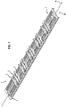
- the lath 2 has a longitudinal and globally planar geometry with a top face T, a bottom face B and a longitudinal symmetry axis A. In use, the lath extends in a substantially horizontal plane.
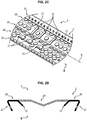
- a central portion 2A is located in the middle of the lath along the longitudinal symmetry axis A and has a V-shaped cross-section as shown in Figure 2D .
- the two side portions 2B are located on each side of the central portion 2A and define two flat and horizontal areas.
- the folded portions 2C are located at each lateral edge of the lath further from the side portions 2B. These folded portions are planar surfaces that are inwardly folded towards the bottom face B of the lath 2.
- the globally rectangular configuration of the lath 2 is well adapted to in-line containers manufacturing processes, in particular processes comprising annealing ovens. However, other configurations may be considered according to other manufacturing equipments or for batch manufacturing processes. In such cases, the lath may adopt, for example, a square or circular shape. Generally speaking, the central portion 2A may adopt a non-planar shape and in particular an inverted V-shape, a W-shape or a U-shape.
- slots 21 are further present along the length of the lath. As seen on Figures 2A-2D , all the slots are parallel to each other and perpendicular to the longitudinal symmetry axis A of the lath. Consequently, they extend through the central and side portions 2A, 2B of the lath. As seen on Figure 2D , two oblique arms 22 protrude into each slot 21 towards the bottom face B of the lath 2. These oblique arms 22 are connected to the side portions 2B and make an angle of about 45° with the plane of the lath 2. Finally, as seen on Figures 2A , 2B two attaching grooves 23 are provided on each extremity of the lath 2 on the central portion 2A.
- the parallel slots may have different alignments regarding the longitudinal symmetry axis A as long as they define groups of at least two parallel slots. Indeed, laths with different shapes may have different groups of at least two parallel slots oriented in different directions.
- the lath 2 is made of any suitable material able to resist the mechanical and thermal conditions existing in containers manufacturing processes.
- Steel is a material of choice, in particular stainless steel for its resistance to thermal oxidation and warping, as for example refractory steels as AISI 310 or 316 L.
- Others refractory materials may also be chosen such as carbon-based composites, austenitic nickel-chromium based super-alloys (Inconel tm ) or Cermet (composite material composed of ceramic and metal).
- a coating may be used to protect the lath material, from corrosion or wear for example.
- Such a coating may be selected on purpose by the skilled person, for example diamond-like carbon (DLC), titanium nitride, nickel oxide, chromium oxide or boron oxide.
- an insert 3 is shown. It has globally a T-shaped geometry with a seat portion 3A on its upper part and a clipping portion 3B on its lower part, both portions being separated by a longitudinal plane 3C. As seen in Figure 3B , the thickness of the seat portion 3A is beveled from the plane 3C to its top edge, on which three V-shaped seats 31 are further provided.
- the clipping portion 3B has a narrowing width from the plane 3C to its bottom edge which defines two opposite corners each consisting of an abutment edge 32 and a lateral edge 33.
- the seat portion 5A and the clipping portion 5B of the insert 5 visible in Figure 6A are not separated by a plane and adopt the same thickness.
- the upper surface of the insert defines seats 51 having a V-shaped geometry with a constant thickness.
- the insert 6 has a constant thickness such as the insert 5 of Figure 6A , but the top edge of the seat portion 6A defines a curvature radius which leads to seats 61 without any sharp edges.
- the insert and their corresponding seats may present other profiles adapted to the different sizes and types of the glass containers.
- vials may require larger seats and two-seat inserts may be more adapted, while four-seat inserts may be preferred for small size cartridges.
- the number of seats per glass containers may also be adapted to the length of the glass containers under manufacturing.
- Inserts are preferably made in a single piece of a non-metallic material, preferably carbon. However, they may comprise two or more materials. These materials may be chosen among refractory materials such as ceramic, in particular refractory ceramic such as steatite, alumino-silicate or zirconium oxide.
- the inserts may be coated for example to protect the non-metallic material from oxidation, degradation and wear and/or to further prevent any stains, lines or microcracks on the surface of the glass containers.
- Such coatings may be selected on purpose by the skilled person, for example chosen among diamond-like carbon (DLC), titanium nitride, nickel oxide, chromium oxide or boron oxide.
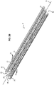
- the transportation system 1 is ready to be used with inserts 3 placed and plugged into the parallel slots 21 of a lath 2.
- the clipping portion 3B of the insert 3 is totally inserted through the thickness of the lath 2 and protrudes out from the bottom face B of the lath 2.
- the abutment edges 32 of the clipping portion 3B are in abutment with the side portions 2B of the lath 2, which prevents the insert 3 from entirely sliding through the parallel slot 21.
- the oblique arms 22 of the parallel slots 21 are in tight frictional contact with the lateral edges 33 of the clipping portion 3B of the insert 3, which prevents the disconnection of the insert 3 from the slot 21, for example because of the lath thermal deformation or the transportation system vibrations during manufacturing processes.
- the interaction of the abutment edges 32 and the lateral edges 33 of the insert 3 with the side portion 2B of the lath 2 and the oblique arm 22 of the parallel slot 21 therefore transversally secures the insert 3 to the lath 2.
- the parallel slot 21 has the same V-shaped cross-section than the V-shaped central portion 2A, movements of the inserts in the longitudinal direction of the lath are prevented and swinging is also prohibited.
- the V-shaped slot 21, the oblique arms 22 and the side portion 2B of the lath together with the clipping portion 3B, the abutment edges 32 and the lateral edges 33 of the insert 3 thus act as securing means for a firm connection between the lath 2 and the insert 3.
- the lath itself shows a significant rigidity and a limited thermal deformation due to the specific geometry of its central V-shape portion 2A and its folded portions 2C.
- the oblique arms 22 may be easily disengaged from the clipping portion 3B with simple tools as small levers or retractors in order to quickly remove the insert 3 from the parallel slot 21. This allows a quick customization of the transportation system, for example when a different configuration of the inserts is required to manufacture glass containers of another type or size.
- the securing means thus allow a firm and reversible connection of the insert 3 to the lath 2.
- the transportation system 1 shown in Figure 5 corresponds to an "in use” configuration, when the glass containers, as for example syringes 4, are placed onto the V-shaped seats 31 of the inserts 3.
- the transportation system is connected by the attaching grooves 23 to the driving system of the annealing oven (not shown).
- each syringe 4 is seated horizontally on at least two non-metallic inserts 3.
- Each syringe contacts the two inserts 3 on its barrel surface, therefore excluding any direct contact or interaction with the syringe extremities (i.e. the tip and/or the flange) with the insert 3 of the lath 2.
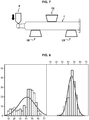
- the tip strength of syringes is generally measured by horizontally maintaining a syringe on a Llyod LRX compression bench CB and applying a compression pin P radially on the extremity of the tip portion.
- the pin P is perpendicularly pressed onto the tip portion of the syringe at a speed of 25 mm/min on a 5 mm depth until breakage, and the maximum load force, expressed in arbitrary units, is measured.
- the average tip strength (x-axis) of syringes carried on a transportation system according to the present invention increased from 41 u.a. to 44 u.a. (top of the Gaussian curves) in comparison to syringes transported on a prior-art system (left box), meaning an increase of about 7 %.
- the y-axis being the population frequency, syringes having a tip strength below 30 u.a. almost disappeared and most of the syringes are now around 50 u.a. This results in a tip strength standard deviation decreasing of about 50 %, as it appears from the width reduction of the Gaussian curves.
- the eccentricity has been measured by positioning horizontally a syringe 4 on a rotating holder H, the head of a micrometric gauge MG (Mitsutoyo, Japan) being in close contact with the surface of the barrel (more precisely the head of the gauge being placed at the half length of the syringe) in order to measure the axial displacement of the head and evaluate the curvature of the global shape of the syringe.
- the syringe is rotated on the rotating holder to find the highest point V1 of the syringe surface.
- V1 is determined
- the syringe is then turned of 180° and a second height V2 is measured.
- the value of eccentricity is then calculated by applying the following formula: (V1-V2)/2, in arbitrary units.
- Figure 10A shows the average eccentricity in arbitrary units and Figure 10B the eccentricity standard deviation obtained for the 165 syringes that have been submitted to heat treatment when transported on a prior-art system or on the system of the present invention.
- the specific geometry of the seat 31 further contributes to the stability of the glass containers 4 when they are carried on the transportation system 1. While the beveled seat geometry of the insert 3 as shown in Figure 3 reduces the contact surface with the glass containers, the constant thickness of the seat 51 of the insert 5 shown in Figure 6A contributes to the stabilization of the glass containers and thus decreases the number of defects generated during the transportation of the containers on the laths. Besides, the smooth seat 61 with its curved edge of the insert 6 shown in Figure 6B contributes to reduce cosmetic defects and flaws in the glass container material. Any of these inserts may thus be chosen by the skilled person to solve specific problems such as vibrations, misalignment or cosmetic defects.
- the transportation system 1 is also very flexible as it authorizes quick configuration exchanges. Indeed, since inserts are reversibly connected to the lath thanks to the presence of the securing means, the inserts may be removed with simple tools to be replaced quickly and easily. In this way, the type and number of inserts may be changed according to the type of containers that are produced but also according to the diameter and length of the glass containers. As a result, only a limited number of laths are required to sustain the manufacturing of a wide range of glass containers. In example, a batch of vials may be annealed in a short time after a batch of cartridges.
Landscapes
- Chemical & Material Sciences (AREA)
- Engineering & Computer Science (AREA)
- Materials Engineering (AREA)
- Organic Chemistry (AREA)
- Details Of Rigid Or Semi-Rigid Containers (AREA)
- Containers Having Bodies Formed In One Piece (AREA)
- Re-Forming, After-Treatment, Cutting And Transporting Of Glass Products (AREA)
- Medical Preparation Storing Or Oral Administration Devices (AREA)
- Packages (AREA)
Claims (14)
- Transportsystem (1) zum Tempern eines Glasbehälters (4) mit einem Zylinder und zwei Enden, wobei das Transportsystem Folgendes umfasst:- eine Leiste (2), die mit mindestens zwei nichtmetallischen Einsätzen (3, 5, 6) versehen ist, wobei die mindestens zwei nichtmetallischen Einsätze (3, 5, 6) derart positioniert sind, dass, wenn ein Glasbehälter auf die Leiste gelegt wird, der Glasbehälter ausschließlich durch den Kontakt zwischen den mindestens zwei nichtmetallischen Einsätzen und dem Zylinder in einer im Wesentlichen horizontalen Position, die relativ zur Leiste fest ist, gehalten wird;- Befestigungsmittel (22, 33), die einen Klemmabschnitt (3B, 5B, 6B) der mindestens zwei nichtmetallischen Einsätze (3, 5, 6) in einem jeweiligen Schlitz (21) der Leiste (2) umkehrbar fest befestigen können.
- Transportsystem (1) nach Anspruch 1, wobei die Schlitze (21) V-förmig sind.
- Transportsystem (1) nach Anspruch 1 oder Anspruch 2, wobei die Leiste (2) ferner zwei Seitenabschnitte (2B) umfasst und wobei der Klemmabschnitt (3B, 5B, 6B) der Einsätze ferner zwei Anschlagkanten (32) umfasst, wobei jede Anschlagkante (32) an einem der zwei Seitenabschnitte (2B) der Leiste in Anschlag ist, wobei die zwei Seitenabschnitte (2B) und die Anschlagkanten (32) einen Teil der Befestigungsmittel bilden.
- Transportsystem nach einem der vorhergehenden Ansprüche, wobei die Befestigungsmittel zwei schräge Arme (22) umfassen, die in engem Reibkontakt mit einer Seitenkante des Klemmabschnitts (3B, 5B, 6B) eines jeweiligen Einsatzes, der im Schlitz (21) aufgenommen ist, in den Schlitz (21) vorstehen.
- Transportsystem (1) nach einem der vorhergehenden Ansprüche, wobei die Einsätze (3, 5, 6) aus Karbon oder Keramik bestehen.
- Transportsystem (1) nach einem der vorhergehenden Ansprüche, wobei die Einsätze (3, 5, 6) ferner einen Sitzabschnitt (3A, 5A, 6A) umfassen, der mindestens einen Sitz (51) aufweist, der einen Teil eines Glasbehälterzylinders berühren soll.
- Transportsystem (1) nach Anspruch 6, wobei der mindestens eine Sitz (51) eine gebogene Kante aufweist.
- Transportsystem (1) nach einem der vorhergehenden Ansprüche, wobei die Leiste (2) aus Edelstahl besteht.
- Transportsystem (1) nach einem der vorhergehenden Ansprüche, wobei die Leiste ferner eine Längssymmetrieachse (A) definiert und wobei die mindestens zwei parallelen Schlitze (21) senkrecht zur Längssymmetrieachse (A) verlaufen.
- Transportsystem (1) nach einem der vorhergehenden Ansprüche, wobei die Leiste einen mittleren Abschnitt (2A), der sich entlang einer Längssymmetrieachse (A) erstreckt, und zwei Seitenabschnitte (2B), die sich auf beiden Seiten des mittleren Abschnitts befinden, umfasst und die parallelen Schlitze (21) sich durch den mittleren Abschnitt und die Seitenabschnitte (2A, 2B) der Leiste (2) erstrecken.
- Transportsystem (1) nach einem der vorhergehenden Ansprüche, das ferner Glasbehälter (4) mit einem Zylinder und zwei Enden umfasst, wobei jeder Glasbehälter (4) nur durch einen Kontakt zwischen dem Zylinder und jedem der mindestens zwei Einsätze (3, 5, 6) auf mindestens zwei Einsätzen (3, 5, 6) liegt.
- Transportsystem (1) nach Anspruch 11, wobei die Glasbehälter Ampullen, Spritzen, Kartuschen oder Fläschchen beinhalten.
- Verfahren zum Tempern eines Glasbehälters mit einem Zylinder und zwei Enden, wobei das Verfahren Folgendes umfasst:- Bereitstellen eines Transportsystems (1) nach einem der Ansprüche 1 bis 10,- Legen eines Glasbehälters (4) auf mindestens zwei nichtmetallische Einsätze (3, 5, 6), die fest an der Leiste (2) des Transportsystems (1) befestigt sind, derart dass der (4) Glasbehälter ausschließlich durch den Kontakt zwischen den mindestens zwei nichtmetallischen Einsätzen (3, 5, 6) und dem Zylinder (4) gehalten wird,- Tragen des mindestens einen Glasbehälters (4) zu einem Temperofen dank des Transportsystems (1), wobei der mindestens eine Glasbehälter (4) relativ zum Transportsystem (1) bewegungslos ist.
- Verfahren nach Anspruch 13, wobei der Glasbehälter eine Ampulle, eine Spritze, eine Kartusche oder ein Fläschchen beinhaltet.
Applications Claiming Priority (2)
| Application Number | Priority Date | Filing Date | Title |
|---|---|---|---|
| EP15305931 | 2015-06-16 | ||
| PCT/EP2016/063685 WO2016202825A1 (en) | 2015-06-16 | 2016-06-15 | Transportation system for annealing glass containers |
Publications (2)
| Publication Number | Publication Date |
|---|---|
| EP3310723A1 EP3310723A1 (de) | 2018-04-25 |
| EP3310723B1 true EP3310723B1 (de) | 2021-05-26 |
Family
ID=53488270
Family Applications (1)
| Application Number | Title | Priority Date | Filing Date |
|---|---|---|---|
| EP16729888.4A Active EP3310723B1 (de) | 2015-06-16 | 2016-06-15 | Transportsystem zum glühen von glasbehältern |
Country Status (5)
| Country | Link |
|---|---|
| US (1) | US10640414B2 (de) |
| EP (1) | EP3310723B1 (de) |
| CN (2) | CN106256795B (de) |
| ES (1) | ES2882595T3 (de) |
| WO (1) | WO2016202825A1 (de) |
Families Citing this family (3)
| Publication number | Priority date | Publication date | Assignee | Title |
|---|---|---|---|---|
| WO2016202825A1 (en) * | 2015-06-16 | 2016-12-22 | Becton Dickinson France | Transportation system for annealing glass containers |
| CN107586011B (zh) * | 2017-08-31 | 2020-05-01 | 肖特新康药品包装有限公司 | 瓶身无接触退火系统 |
| CN112225446A (zh) * | 2020-10-20 | 2021-01-15 | 涡阳县高炉创新包装有限责任公司 | 一种玻璃瓶退火行走装置 |
Family Cites Families (9)
| Publication number | Priority date | Publication date | Assignee | Title |
|---|---|---|---|---|
| US3885530A (en) | 1974-07-03 | 1975-05-27 | Exxon Research Engineering Co | Shield tube supports |
| JPS5284118A (en) | 1976-01-06 | 1977-07-13 | Kubota Ltd | Heat treatment of ductile cast iron tube made by centrifugal casting |
| EP0131955B2 (de) | 1983-07-19 | 1993-01-20 | A.P.T. Anlagen für Pyrotechnik GmbH | Verfahren zur Wärmebehandlung von zylindrischen Gegenständen, insbesondere Röhren, insbesondere aus keramischem Material, und Durchlaufofen zur Durchführung des Verfahrens |
| DE3915718C1 (de) | 1989-05-13 | 1990-09-20 | Schniering, Alfred, Dipl.-Ing., 4390 Gladbeck, De | |
| IT244025Y1 (it) | 1998-05-25 | 2002-03-07 | Euromatic Srl | Forno per trattamento termico di contenitori in vetro in continuo |
| DE19841042A1 (de) | 1998-09-09 | 2000-03-16 | Eisenmann Kg Maschbau | Verfahren und Einrichtung zum Transport von Werkstücken in einem Industrieofen |
| JP2000226117A (ja) | 1999-02-05 | 2000-08-15 | Showa Kikai Kk | 棒状体の搬送装置 |
| JP2009155062A (ja) | 2007-12-27 | 2009-07-16 | Jfe Steel Corp | 鋼管のレバー揺動式割出し装置 |
| WO2016202825A1 (en) * | 2015-06-16 | 2016-12-22 | Becton Dickinson France | Transportation system for annealing glass containers |
-
2016
- 2016-06-15 WO PCT/EP2016/063685 patent/WO2016202825A1/en not_active Ceased
- 2016-06-15 EP EP16729888.4A patent/EP3310723B1/de active Active
- 2016-06-15 ES ES16729888T patent/ES2882595T3/es active Active
- 2016-06-15 US US15/736,021 patent/US10640414B2/en active Active
- 2016-06-16 CN CN201610427892.2A patent/CN106256795B/zh active Active
- 2016-06-16 CN CN201620588629.7U patent/CN206051850U/zh active Active
Also Published As
| Publication number | Publication date |
|---|---|
| EP3310723A1 (de) | 2018-04-25 |
| US20180170791A1 (en) | 2018-06-21 |
| CN106256795A (zh) | 2016-12-28 |
| CN106256795B (zh) | 2019-06-28 |
| ES2882595T3 (es) | 2021-12-02 |
| WO2016202825A1 (en) | 2016-12-22 |
| US10640414B2 (en) | 2020-05-05 |
| CN206051850U (zh) | 2017-03-29 |
Similar Documents
| Publication | Publication Date | Title |
|---|---|---|
| EP3310723B1 (de) | Transportsystem zum glühen von glasbehältern | |
| US9153466B2 (en) | Wafer boat | |
| EP1690611B1 (de) | Rasierklinge und Herstellungsverfahren | |
| US8764351B2 (en) | Cutting insert with flexibility aperture and cutting tool therefor | |
| EP2718037B1 (de) | Grundplattenanordnung mit lagerflächenmechanismus, verfahren zum halten eines stanzwerkzeugs und stanzwerkzeug zur verwendung damit | |
| EP3892593A1 (de) | Vorrichtung zur bearbeitung von glaskörpern | |
| CN104098263B (zh) | 输送具有不同于圆形横截面的横截面的玻璃管束或玻璃棒束的设备和方法及其用途 | |
| US20180030560A1 (en) | Article processing fixture | |
| US20160016842A1 (en) | Glass Cutting Tool | |
| US11504777B2 (en) | Tool system | |
| US8686312B2 (en) | Weld cap changing tools | |
| US10682708B2 (en) | Carrier tool, cutting insert, and clamping element | |
| JP5548184B2 (ja) | 平らな材料を切断するための切断定規 | |
| KR20160129900A (ko) | 공구 이송대 | |
| CN105263677B (zh) | 用于七重切割的夹紧系统 | |
| JP2015067531A (ja) | ガラス母材の支持構造、支持ピンおよびガラス母材の製造方法 | |
| US20190024704A1 (en) | High temperature high load compatible bearing | |
| TWI869390B (zh) | 保持器單元及銷 | |
| US20240115016A1 (en) | Jewelry setting tools and methods | |
| EP3176272A1 (de) | Fördervorrichtung für wärmebehandlungsvorrichtung und wärmebehandlungsvorrichtung | |
| EP3064287B1 (de) | Maschine zum vorflanschen, einfassen und flanschen eines abschnitts eines rohres mit einem schrägen rohrende | |
| US11724382B2 (en) | Workpiece storage device and workpiece handling system having a workpiece storage device | |
| CN119427297A (zh) | 一种模切刀模放置架及其操作方法 | |
| Tatjanchenko et al. | Perspectives of heightening of exactitude fair handlings of holes by the axial instrument | |
| US20200255941A1 (en) | Supports for chemical vapor deposition coating applications |
Legal Events
| Date | Code | Title | Description |
|---|---|---|---|
| STAA | Information on the status of an ep patent application or granted ep patent |
Free format text: STATUS: THE INTERNATIONAL PUBLICATION HAS BEEN MADE |
|
| PUAI | Public reference made under article 153(3) epc to a published international application that has entered the european phase |
Free format text: ORIGINAL CODE: 0009012 |
|
| STAA | Information on the status of an ep patent application or granted ep patent |
Free format text: STATUS: REQUEST FOR EXAMINATION WAS MADE |
|
| 17P | Request for examination filed |
Effective date: 20180115 |
|
| AK | Designated contracting states |
Kind code of ref document: A1 Designated state(s): AL AT BE BG CH CY CZ DE DK EE ES FI FR GB GR HR HU IE IS IT LI LT LU LV MC MK MT NL NO PL PT RO RS SE SI SK SM TR |
|
| AX | Request for extension of the european patent |
Extension state: BA ME |
|
| DAV | Request for validation of the european patent (deleted) | ||
| DAX | Request for extension of the european patent (deleted) | ||
| GRAP | Despatch of communication of intention to grant a patent |
Free format text: ORIGINAL CODE: EPIDOSNIGR1 |
|
| STAA | Information on the status of an ep patent application or granted ep patent |
Free format text: STATUS: GRANT OF PATENT IS INTENDED |
|
| INTG | Intention to grant announced |
Effective date: 20210317 |
|
| GRAS | Grant fee paid |
Free format text: ORIGINAL CODE: EPIDOSNIGR3 |
|
| GRAA | (expected) grant |
Free format text: ORIGINAL CODE: 0009210 |
|
| STAA | Information on the status of an ep patent application or granted ep patent |
Free format text: STATUS: THE PATENT HAS BEEN GRANTED |
|
| AK | Designated contracting states |
Kind code of ref document: B1 Designated state(s): AL AT BE BG CH CY CZ DE DK EE ES FI FR GB GR HR HU IE IS IT LI LT LU LV MC MK MT NL NO PL PT RO RS SE SI SK SM TR |
|
| REG | Reference to a national code |
Ref country code: GB Ref legal event code: FG4D |
|
| REG | Reference to a national code |
Ref country code: CH Ref legal event code: EP |
|
| REG | Reference to a national code |
Ref country code: AT Ref legal event code: REF Ref document number: 1396081 Country of ref document: AT Kind code of ref document: T Effective date: 20210615 |
|
| REG | Reference to a national code |
Ref country code: DE Ref legal event code: R096 Ref document number: 602016058387 Country of ref document: DE |
|
| REG | Reference to a national code |
Ref country code: IE Ref legal event code: FG4D |
|
| REG | Reference to a national code |
Ref country code: LT Ref legal event code: MG9D |
|
| REG | Reference to a national code |
Ref country code: AT Ref legal event code: MK05 Ref document number: 1396081 Country of ref document: AT Kind code of ref document: T Effective date: 20210526 |
|
| PG25 | Lapsed in a contracting state [announced via postgrant information from national office to epo] |
Ref country code: HR Free format text: LAPSE BECAUSE OF FAILURE TO SUBMIT A TRANSLATION OF THE DESCRIPTION OR TO PAY THE FEE WITHIN THE PRESCRIBED TIME-LIMIT Effective date: 20210526 Ref country code: AT Free format text: LAPSE BECAUSE OF FAILURE TO SUBMIT A TRANSLATION OF THE DESCRIPTION OR TO PAY THE FEE WITHIN THE PRESCRIBED TIME-LIMIT Effective date: 20210526 Ref country code: BG Free format text: LAPSE BECAUSE OF FAILURE TO SUBMIT A TRANSLATION OF THE DESCRIPTION OR TO PAY THE FEE WITHIN THE PRESCRIBED TIME-LIMIT Effective date: 20210826 Ref country code: LT Free format text: LAPSE BECAUSE OF FAILURE TO SUBMIT A TRANSLATION OF THE DESCRIPTION OR TO PAY THE FEE WITHIN THE PRESCRIBED TIME-LIMIT Effective date: 20210526 Ref country code: FI Free format text: LAPSE BECAUSE OF FAILURE TO SUBMIT A TRANSLATION OF THE DESCRIPTION OR TO PAY THE FEE WITHIN THE PRESCRIBED TIME-LIMIT Effective date: 20210526 |
|
| REG | Reference to a national code |
Ref country code: NL Ref legal event code: MP Effective date: 20210526 |
|
| PG25 | Lapsed in a contracting state [announced via postgrant information from national office to epo] |
Ref country code: PT Free format text: LAPSE BECAUSE OF FAILURE TO SUBMIT A TRANSLATION OF THE DESCRIPTION OR TO PAY THE FEE WITHIN THE PRESCRIBED TIME-LIMIT Effective date: 20210927 Ref country code: PL Free format text: LAPSE BECAUSE OF FAILURE TO SUBMIT A TRANSLATION OF THE DESCRIPTION OR TO PAY THE FEE WITHIN THE PRESCRIBED TIME-LIMIT Effective date: 20210526 Ref country code: NO Free format text: LAPSE BECAUSE OF FAILURE TO SUBMIT A TRANSLATION OF THE DESCRIPTION OR TO PAY THE FEE WITHIN THE PRESCRIBED TIME-LIMIT Effective date: 20210826 Ref country code: RS Free format text: LAPSE BECAUSE OF FAILURE TO SUBMIT A TRANSLATION OF THE DESCRIPTION OR TO PAY THE FEE WITHIN THE PRESCRIBED TIME-LIMIT Effective date: 20210526 Ref country code: SE Free format text: LAPSE BECAUSE OF FAILURE TO SUBMIT A TRANSLATION OF THE DESCRIPTION OR TO PAY THE FEE WITHIN THE PRESCRIBED TIME-LIMIT Effective date: 20210526 Ref country code: IS Free format text: LAPSE BECAUSE OF FAILURE TO SUBMIT A TRANSLATION OF THE DESCRIPTION OR TO PAY THE FEE WITHIN THE PRESCRIBED TIME-LIMIT Effective date: 20210926 Ref country code: GR Free format text: LAPSE BECAUSE OF FAILURE TO SUBMIT A TRANSLATION OF THE DESCRIPTION OR TO PAY THE FEE WITHIN THE PRESCRIBED TIME-LIMIT Effective date: 20210827 Ref country code: LV Free format text: LAPSE BECAUSE OF FAILURE TO SUBMIT A TRANSLATION OF THE DESCRIPTION OR TO PAY THE FEE WITHIN THE PRESCRIBED TIME-LIMIT Effective date: 20210526 |
|
| REG | Reference to a national code |
Ref country code: ES Ref legal event code: FG2A Ref document number: 2882595 Country of ref document: ES Kind code of ref document: T3 Effective date: 20211202 |
|
| PG25 | Lapsed in a contracting state [announced via postgrant information from national office to epo] |
Ref country code: NL Free format text: LAPSE BECAUSE OF FAILURE TO SUBMIT A TRANSLATION OF THE DESCRIPTION OR TO PAY THE FEE WITHIN THE PRESCRIBED TIME-LIMIT Effective date: 20210526 |
|
| PG25 | Lapsed in a contracting state [announced via postgrant information from national office to epo] |
Ref country code: DK Free format text: LAPSE BECAUSE OF FAILURE TO SUBMIT A TRANSLATION OF THE DESCRIPTION OR TO PAY THE FEE WITHIN THE PRESCRIBED TIME-LIMIT Effective date: 20210526 Ref country code: CZ Free format text: LAPSE BECAUSE OF FAILURE TO SUBMIT A TRANSLATION OF THE DESCRIPTION OR TO PAY THE FEE WITHIN THE PRESCRIBED TIME-LIMIT Effective date: 20210526 Ref country code: EE Free format text: LAPSE BECAUSE OF FAILURE TO SUBMIT A TRANSLATION OF THE DESCRIPTION OR TO PAY THE FEE WITHIN THE PRESCRIBED TIME-LIMIT Effective date: 20210526 Ref country code: SM Free format text: LAPSE BECAUSE OF FAILURE TO SUBMIT A TRANSLATION OF THE DESCRIPTION OR TO PAY THE FEE WITHIN THE PRESCRIBED TIME-LIMIT Effective date: 20210526 Ref country code: SK Free format text: LAPSE BECAUSE OF FAILURE TO SUBMIT A TRANSLATION OF THE DESCRIPTION OR TO PAY THE FEE WITHIN THE PRESCRIBED TIME-LIMIT Effective date: 20210526 Ref country code: RO Free format text: LAPSE BECAUSE OF FAILURE TO SUBMIT A TRANSLATION OF THE DESCRIPTION OR TO PAY THE FEE WITHIN THE PRESCRIBED TIME-LIMIT Effective date: 20210526 |
|
| REG | Reference to a national code |
Ref country code: DE Ref legal event code: R097 Ref document number: 602016058387 Country of ref document: DE |
|
| REG | Reference to a national code |
Ref country code: BE Ref legal event code: MM Effective date: 20210630 |
|
| PLBE | No opposition filed within time limit |
Free format text: ORIGINAL CODE: 0009261 |
|
| STAA | Information on the status of an ep patent application or granted ep patent |
Free format text: STATUS: NO OPPOSITION FILED WITHIN TIME LIMIT |
|
| PG25 | Lapsed in a contracting state [announced via postgrant information from national office to epo] |
Ref country code: MC Free format text: LAPSE BECAUSE OF FAILURE TO SUBMIT A TRANSLATION OF THE DESCRIPTION OR TO PAY THE FEE WITHIN THE PRESCRIBED TIME-LIMIT Effective date: 20210526 Ref country code: LU Free format text: LAPSE BECAUSE OF NON-PAYMENT OF DUE FEES Effective date: 20210615 |
|
| PG25 | Lapsed in a contracting state [announced via postgrant information from national office to epo] |
Ref country code: IE Free format text: LAPSE BECAUSE OF NON-PAYMENT OF DUE FEES Effective date: 20210615 |
|
| 26N | No opposition filed |
Effective date: 20220301 |
|
| PG25 | Lapsed in a contracting state [announced via postgrant information from national office to epo] |
Ref country code: IS Free format text: LAPSE BECAUSE OF FAILURE TO SUBMIT A TRANSLATION OF THE DESCRIPTION OR TO PAY THE FEE WITHIN THE PRESCRIBED TIME-LIMIT Effective date: 20210926 Ref country code: AL Free format text: LAPSE BECAUSE OF FAILURE TO SUBMIT A TRANSLATION OF THE DESCRIPTION OR TO PAY THE FEE WITHIN THE PRESCRIBED TIME-LIMIT Effective date: 20210526 |
|
| PG25 | Lapsed in a contracting state [announced via postgrant information from national office to epo] |
Ref country code: BE Free format text: LAPSE BECAUSE OF NON-PAYMENT OF DUE FEES Effective date: 20210630 |
|
| PG25 | Lapsed in a contracting state [announced via postgrant information from national office to epo] |
Ref country code: CY Free format text: LAPSE BECAUSE OF FAILURE TO SUBMIT A TRANSLATION OF THE DESCRIPTION OR TO PAY THE FEE WITHIN THE PRESCRIBED TIME-LIMIT Effective date: 20210526 |
|
| PG25 | Lapsed in a contracting state [announced via postgrant information from national office to epo] |
Ref country code: HU Free format text: LAPSE BECAUSE OF FAILURE TO SUBMIT A TRANSLATION OF THE DESCRIPTION OR TO PAY THE FEE WITHIN THE PRESCRIBED TIME-LIMIT; INVALID AB INITIO Effective date: 20160615 |
|
| PG25 | Lapsed in a contracting state [announced via postgrant information from national office to epo] |
Ref country code: MK Free format text: LAPSE BECAUSE OF FAILURE TO SUBMIT A TRANSLATION OF THE DESCRIPTION OR TO PAY THE FEE WITHIN THE PRESCRIBED TIME-LIMIT Effective date: 20210526 |
|
| PG25 | Lapsed in a contracting state [announced via postgrant information from national office to epo] |
Ref country code: MT Free format text: LAPSE BECAUSE OF FAILURE TO SUBMIT A TRANSLATION OF THE DESCRIPTION OR TO PAY THE FEE WITHIN THE PRESCRIBED TIME-LIMIT Effective date: 20210526 |
|
| PGFP | Annual fee paid to national office [announced via postgrant information from national office to epo] |
Ref country code: DE Payment date: 20250520 Year of fee payment: 10 |
|
| PGFP | Annual fee paid to national office [announced via postgrant information from national office to epo] |
Ref country code: GB Payment date: 20250520 Year of fee payment: 10 |
|
| PGFP | Annual fee paid to national office [announced via postgrant information from national office to epo] |
Ref country code: IT Payment date: 20250520 Year of fee payment: 10 |
|
| PGFP | Annual fee paid to national office [announced via postgrant information from national office to epo] |
Ref country code: FR Payment date: 20250520 Year of fee payment: 10 |
|
| PGFP | Annual fee paid to national office [announced via postgrant information from national office to epo] |
Ref country code: ES Payment date: 20250701 Year of fee payment: 10 |
|
| PGFP | Annual fee paid to national office [announced via postgrant information from national office to epo] |
Ref country code: CH Payment date: 20250701 Year of fee payment: 10 |
|
| PG25 | Lapsed in a contracting state [announced via postgrant information from national office to epo] |
Ref country code: TR Free format text: LAPSE BECAUSE OF FAILURE TO SUBMIT A TRANSLATION OF THE DESCRIPTION OR TO PAY THE FEE WITHIN THE PRESCRIBED TIME-LIMIT Effective date: 20210526 |