EP3311751A1 - Endoskop - Google Patents
Endoskop Download PDFInfo
- Publication number
- EP3311751A1 EP3311751A1 EP16811726.5A EP16811726A EP3311751A1 EP 3311751 A1 EP3311751 A1 EP 3311751A1 EP 16811726 A EP16811726 A EP 16811726A EP 3311751 A1 EP3311751 A1 EP 3311751A1
- Authority
- EP
- European Patent Office
- Prior art keywords
- treatment instrument
- distal
- distal end
- insertion section
- endoscope
- Prior art date
- Legal status (The legal status is an assumption and is not a legal conclusion. Google has not performed a legal analysis and makes no representation as to the accuracy of the status listed.)
- Withdrawn
Links
- 238000005452 bending Methods 0.000 claims abstract description 92
- 238000003780 insertion Methods 0.000 claims abstract description 90
- 230000037431 insertion Effects 0.000 claims abstract description 90
- 239000011248 coating agent Substances 0.000 claims abstract description 8
- 238000000576 coating method Methods 0.000 claims abstract description 8
- 238000002604 ultrasonography Methods 0.000 claims description 94
- 238000003384 imaging method Methods 0.000 claims description 16
- 230000003287 optical effect Effects 0.000 claims description 4
- 229910045601 alloy Inorganic materials 0.000 claims description 3
- 239000000956 alloy Substances 0.000 claims description 3
- 238000004140 cleaning Methods 0.000 abstract description 11
- XLYOFNOQVPJJNP-UHFFFAOYSA-N water Substances O XLYOFNOQVPJJNP-UHFFFAOYSA-N 0.000 description 19
- 238000010586 diagram Methods 0.000 description 6
- 238000005286 illumination Methods 0.000 description 6
- 230000003247 decreasing effect Effects 0.000 description 4
- 239000002184 metal Substances 0.000 description 4
- 239000011347 resin Substances 0.000 description 3
- 229920005989 resin Polymers 0.000 description 3
- 238000007789 sealing Methods 0.000 description 3
- 239000000853 adhesive Substances 0.000 description 2
- 230000001070 adhesive effect Effects 0.000 description 2
- 230000005540 biological transmission Effects 0.000 description 2
- 238000004519 manufacturing process Methods 0.000 description 2
- 238000000034 method Methods 0.000 description 2
- 238000012986 modification Methods 0.000 description 2
- 230000004048 modification Effects 0.000 description 2
- 210000000056 organ Anatomy 0.000 description 2
- 230000002730 additional effect Effects 0.000 description 1
- 238000005219 brazing Methods 0.000 description 1
- 238000006243 chemical reaction Methods 0.000 description 1
- 230000000694 effects Effects 0.000 description 1
- 239000013307 optical fiber Substances 0.000 description 1
- 238000003825 pressing Methods 0.000 description 1
- 229910052710 silicon Inorganic materials 0.000 description 1
- 239000010703 silicon Substances 0.000 description 1
- 239000010935 stainless steel Substances 0.000 description 1
- 229910001220 stainless steel Inorganic materials 0.000 description 1
Images





Classifications
-
- A—HUMAN NECESSITIES
- A61—MEDICAL OR VETERINARY SCIENCE; HYGIENE
- A61B—DIAGNOSIS; SURGERY; IDENTIFICATION
- A61B8/00—Diagnosis using ultrasonic, sonic or infrasonic waves
- A61B8/12—Diagnosis using ultrasonic, sonic or infrasonic waves in body cavities or body tracts, e.g. by using catheters
-
- A—HUMAN NECESSITIES
- A61—MEDICAL OR VETERINARY SCIENCE; HYGIENE
- A61B—DIAGNOSIS; SURGERY; IDENTIFICATION
- A61B1/00—Instruments for performing medical examinations of the interior of cavities or tubes of the body by visual or photographical inspection, e.g. endoscopes; Illuminating arrangements therefor
- A61B1/00002—Operational features of endoscopes
- A61B1/00011—Operational features of endoscopes characterised by signal transmission
-
- A—HUMAN NECESSITIES
- A61—MEDICAL OR VETERINARY SCIENCE; HYGIENE
- A61B—DIAGNOSIS; SURGERY; IDENTIFICATION
- A61B1/00—Instruments for performing medical examinations of the interior of cavities or tubes of the body by visual or photographical inspection, e.g. endoscopes; Illuminating arrangements therefor
- A61B1/00064—Constructional details of the endoscope body
- A61B1/00071—Insertion part of the endoscope body
- A61B1/0008—Insertion part of the endoscope body characterised by distal tip features
- A61B1/00097—Sensors
-
- A—HUMAN NECESSITIES
- A61—MEDICAL OR VETERINARY SCIENCE; HYGIENE
- A61B—DIAGNOSIS; SURGERY; IDENTIFICATION
- A61B1/00—Instruments for performing medical examinations of the interior of cavities or tubes of the body by visual or photographical inspection, e.g. endoscopes; Illuminating arrangements therefor
- A61B1/00064—Constructional details of the endoscope body
- A61B1/00071—Insertion part of the endoscope body
- A61B1/0008—Insertion part of the endoscope body characterised by distal tip features
- A61B1/00098—Deflecting means for inserted tools
-
- A—HUMAN NECESSITIES
- A61—MEDICAL OR VETERINARY SCIENCE; HYGIENE
- A61B—DIAGNOSIS; SURGERY; IDENTIFICATION
- A61B1/00—Instruments for performing medical examinations of the interior of cavities or tubes of the body by visual or photographical inspection, e.g. endoscopes; Illuminating arrangements therefor
- A61B1/005—Flexible endoscopes
- A61B1/0051—Flexible endoscopes with controlled bending of insertion part
-
- A—HUMAN NECESSITIES
- A61—MEDICAL OR VETERINARY SCIENCE; HYGIENE
- A61B—DIAGNOSIS; SURGERY; IDENTIFICATION
- A61B1/00—Instruments for performing medical examinations of the interior of cavities or tubes of the body by visual or photographical inspection, e.g. endoscopes; Illuminating arrangements therefor
- A61B1/012—Instruments for performing medical examinations of the interior of cavities or tubes of the body by visual or photographical inspection, e.g. endoscopes; Illuminating arrangements therefor characterised by internal passages or accessories therefor
- A61B1/018—Instruments for performing medical examinations of the interior of cavities or tubes of the body by visual or photographical inspection, e.g. endoscopes; Illuminating arrangements therefor characterised by internal passages or accessories therefor for receiving instruments
-
- G—PHYSICS
- G02—OPTICS
- G02B—OPTICAL ELEMENTS, SYSTEMS OR APPARATUS
- G02B23/00—Telescopes, e.g. binoculars; Periscopes; Instruments for viewing the inside of hollow bodies; Viewfinders; Optical aiming or sighting devices
- G02B23/24—Instruments or systems for viewing the inside of hollow bodies, e.g. fibrescopes
- G02B23/2476—Non-optical details, e.g. housings, mountings, supports
-
- A—HUMAN NECESSITIES
- A61—MEDICAL OR VETERINARY SCIENCE; HYGIENE
- A61B—DIAGNOSIS; SURGERY; IDENTIFICATION
- A61B1/00—Instruments for performing medical examinations of the interior of cavities or tubes of the body by visual or photographical inspection, e.g. endoscopes; Illuminating arrangements therefor
- A61B1/00002—Operational features of endoscopes
- A61B1/00004—Operational features of endoscopes characterised by electronic signal processing
- A61B1/00009—Operational features of endoscopes characterised by electronic signal processing of image signals during a use of endoscope
- A61B1/000095—Operational features of endoscopes characterised by electronic signal processing of image signals during a use of endoscope for image enhancement
-
- A—HUMAN NECESSITIES
- A61—MEDICAL OR VETERINARY SCIENCE; HYGIENE
- A61B—DIAGNOSIS; SURGERY; IDENTIFICATION
- A61B1/00—Instruments for performing medical examinations of the interior of cavities or tubes of the body by visual or photographical inspection, e.g. endoscopes; Illuminating arrangements therefor
- A61B1/00064—Constructional details of the endoscope body
-
- A—HUMAN NECESSITIES
- A61—MEDICAL OR VETERINARY SCIENCE; HYGIENE
- A61B—DIAGNOSIS; SURGERY; IDENTIFICATION
- A61B1/00—Instruments for performing medical examinations of the interior of cavities or tubes of the body by visual or photographical inspection, e.g. endoscopes; Illuminating arrangements therefor
- A61B1/00163—Optical arrangements
- A61B1/00165—Optical arrangements with light-conductive means, e.g. fibre optics
-
- A—HUMAN NECESSITIES
- A61—MEDICAL OR VETERINARY SCIENCE; HYGIENE
- A61B—DIAGNOSIS; SURGERY; IDENTIFICATION
- A61B1/00—Instruments for performing medical examinations of the interior of cavities or tubes of the body by visual or photographical inspection, e.g. endoscopes; Illuminating arrangements therefor
- A61B1/005—Flexible endoscopes
- A61B1/0051—Flexible endoscopes with controlled bending of insertion part
- A61B1/0057—Constructional details of force transmission elements, e.g. control wires
-
- A—HUMAN NECESSITIES
- A61—MEDICAL OR VETERINARY SCIENCE; HYGIENE
- A61B—DIAGNOSIS; SURGERY; IDENTIFICATION
- A61B1/00—Instruments for performing medical examinations of the interior of cavities or tubes of the body by visual or photographical inspection, e.g. endoscopes; Illuminating arrangements therefor
- A61B1/012—Instruments for performing medical examinations of the interior of cavities or tubes of the body by visual or photographical inspection, e.g. endoscopes; Illuminating arrangements therefor characterised by internal passages or accessories therefor
-
- G—PHYSICS
- G02—OPTICS
- G02B—OPTICAL ELEMENTS, SYSTEMS OR APPARATUS
- G02B23/00—Telescopes, e.g. binoculars; Periscopes; Instruments for viewing the inside of hollow bodies; Viewfinders; Optical aiming or sighting devices
- G02B23/24—Instruments or systems for viewing the inside of hollow bodies, e.g. fibrescopes
- G02B23/26—Instruments or systems for viewing the inside of hollow bodies, e.g. fibrescopes using light guides
Definitions
- the present invention relates to an endoscope.
- Endoscopes are known that are inserted into subjects' bodies to perform observation or the like of regions to be examined, and the endoscopes are widely used in medical field and the like.
- some endoscopes include treatment instrument raisers which deliver to affected areas treatment instruments, such as puncture needles, for treatment in subjects.
- an endoscope which includes a treatment instrument raiser having a multi-joint structure obtained by turnably connecting flat plate members in sequence, and a wire for raising operation, connected to a distal end of the treatment instrument raiser.
- a user such as a physician
- flat plate members of the treatment instrument raiser are sequentially turned, and a treatment instrument is raised.
- Patent Literature 1 JP 2000-116598 A
- the present invention has been made in view of the above problems, and an object of the present invention is to provide an endoscope which has improved cleaning efficiency.
- an endoscope includes: an insertion section inserted into a subject; an operating unit continuously connected to a proximal end of the insertion section; an observation unit disposed at a distal end of the insertion section, and configured to observe the subject; a treatment instrument insertion passage configured to allow insertion of a treatment instrument providing medical treatment to the subject, and project the treatment instrument from a distal end portion of the insertion section; a distal bending portion disposed at a distal end of the treatment instrument insertion passage, and configured to bend according to a raising operation of the operating unit and raise the treatment instrument; and a coating portion provided to cover the distal bending portion.
- the distal bending portion changes, according to the raising operation of the operating unit, a direction in which the treatment instrument projects, independently of a direction in which the observation unit performs observation.
- the endoscope according to one aspect of the present invention includes a wire disposed along a direction in which the insertion section extends, and connected to the operating unit, and the wire includes a distal end portion covered by the coating portion.
- the distal bending portion has an oval cross-section orthogonal to a direction in which the insertion section extends.
- the endoscope according to one aspect of the present invention includes two wires disposed along a direction in which the insertion section extends.
- the endoscope according to one aspect of the present invention includes four wires disposed along a direction in which the insertion section extends.
- the endoscope according to one aspect of the present invention includes the distal bending portion includes a tube including a super elastic alloy and including a slit formed to reduce power required for the bending operation.
- the endoscope according to one aspect of the present invention includes a distal rigid portion disposed near a distal end of the insertion section, and formed with an aperture portion, and, in a cross-section orthogonal to a direction in which the insertion section extends, the distal bending portion in an initial state before the bending is stored in the aperture portion.
- the endoscope includes the observation unit includes: an imaging unit including an optical system focusing light reflected from an object to be observed, and an imaging element converting the focused light to an electrical signal, and outputting the electrical signal, or an ultrasound transducer unit receiving an ultrasound wave reflected from an object to be observed to output an electrical signal.
- the present invention provides an endoscope which has improved cleaning efficiency.
- an ultrasound endoscope including an ultrasound transducer for ultrasound observation of an object to be observed is described as an example, but the present invention can be applied to general endoscopes using treatment instruments such as puncture needles for treatment in subjects.
- FIG. 1 is a schematic view illustrating a configuration of an ultrasound diagnostic system including an ultrasound endoscope according to a first embodiment of the present invention.
- An ultrasound diagnostic system 1 illustrated in FIG. 1 includes an ultrasound endoscope 2, an endoscope observation device 3, an ultrasound observation device 4, a display device 5, a light source device 6, a video cable 7 connecting the ultrasound endoscope 2 and the endoscope observation device 3, an ultrasound cable 8 connecting the ultrasound endoscope 2 and the ultrasound observation device 4, and a light source cable 9 connecting the ultrasound endoscope 2 and the light source device 6.
- the ultrasound endoscope 2 is an endoscope which includes, as an observation unit observing an object to be observed, an imaging unit including an optical system focusing light reflected from the object to be observed, and an imaging element converting the focused light to an electrical signal, and outputting the electrical signal and an ultrasound transducer unit receiving an ultrasound wave reflected from an object to be observed to output an electrical signal.
- the endoscope observation device 3 controls an endoscopic observation function, and processes an output signal output from the ultrasound endoscope 2 during endoscopic observation.
- the ultrasound observation device 4 controls an ultrasound observation function, and processes an output signal output from the ultrasound endoscope 2 during ultrasound observation.
- the display device 5 for example acquires signals output from the endoscope observation device 3 and the ultrasound observation device 4, and appropriately displays at least one of an endoscopic image and an ultrasound tomographic image.
- the light source device 6 includes a light source for supplying illumination light for endoscopic observation.
- the ultrasound endoscope 2 includes an insertion section 10 having a distal end disposed with the observation unit, and inserted into a subject, an operating unit 11 continuously connected to a proximal end of the insertion section 10, a universal cord 12 extending from a side portion of the operating unit 11, and a connector portion 13 continuously connected to the universal cord 12, and connected to the video cable 7, the ultrasound cable 8, and the light source cable 9.
- a direction in which the insertion section 10 is inserted is defined as "insertion direction”
- distal end represents a leading end in the insertion direction
- proximal end represents an opposite end (near the operating unit 11) to the leading end in the insertion direction.
- the insertion section 10 includes, sequentially from the distal end, a distal end portion 10a, a bending section 10b configured to be bent according to rotation operation of a bending knob 11a provided at the operating unit 11, and a flexible tube portion 10c having flexibility.
- a proximal end of the flexible tube portion 10c is continuously connected to a distal end of the operating unit 11.
- a distal end portion of a treatment instrument channel described later is disposed to project a distal end of a treatment instrument.
- the operating unit 11 includes the bending knob 11a. Furthermore, the operating unit 11 is provided with a treatment instrument insertion opening 11b introducing, into the subject, a puncture needle or the like as the treatment instrument providing medical treatment to the subject.
- the insertion section 10 is internally provided with a treatment instrument insertion passage described later, and the treatment instrument insertion opening 11b is formed as an insertion opening for the treatment instrument insertion passage.
- the ultrasound endoscope 2 and the endoscope observation device 3 are electrically connected by the video cable 7 connected to the connector portion 13.
- the ultrasound endoscope 2 and the ultrasound observation device 4 are electrically connected by the ultrasound cable 8 connected to the connector portion 13.
- the light source cable 9 has an optical fiber cable. The ultrasound endoscope 2 and the light source device 6 guide illumination light from the light source of the light source device 6 to the ultrasound endoscope 2 by the light source cable 9 connected to the connector portion 13.
- FIG. 2 is a schematic partial cross-sectional view of a distal rigid portion of the ultrasound endoscope illustrated in FIG. 1 .
- the distal end portion 10a includes a distal rigid portion 101 positioned near the distal end of the insertion section 10, an ultrasound transducer unit 102 disposed at a distal end of the distal rigid portion 101, and a signal cable 103 connected to a proximal end of the ultrasound transducer unit 102.
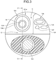
- FIG. 3 is a cross-sectional view taken along the line A1-A1 of FIG. 2 .
- the distal end portion 10a includes the distal end portion of a treatment instrument channel 104 through which a treatment instrument 14 is inserted, an illumination unit 105, an imaging unit 106, and an air/water opening 107.
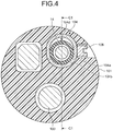
- FIG. 4 is a cross-sectional view taken along the line B1-B1 of FIG. 2 .
- the distal end portion 10a includes a screw 108.
- the cross-section of FIG. 2 is a cross-section corresponding to the line C1-C1 of FIGS. 3 and 4 .
- "upward” represents an upper side of a drawing of each figure, as illustrated in FIG. 2
- “downward” represents a lower side of a drawing of each figure, as illustrated in FIG. 2 , in the following description.
- the distal rigid portion 101 includes a rigid member made of a metal, a rigid resin, or the like.
- the distal rigid portion 101 includes an aperture portion 101a formed to store the distal end portion of the treatment instrument channel 104.
- the ultrasound transducer unit 102 includes an ultrasound transducer transmitting an ultrasound wave, and receiving an ultrasound wave (ultrasound echo) reflected from the object to be observed.
- An observation direction of the ultrasound transducer unit 102 is within a predetermined range of a lateral side (upper side in the drawing of FIG. 2 ) of the insertion section 10. This observation direction of the ultrasound transducer unit 102 can be changed by bending movement of the bending section 10b.
- the signal cable 103 is connected to the ultrasound transducer unit 102, and the signal cable 103 is electrically connected to the ultrasound observation device 4 through the universal cord 12 and the ultrasound cable 8.
- the treatment instrument channel 104 has a tubular shape, and projects the treatment instrument 14 inserted from the treatment instrument insertion opening 11b of the operating unit 11 from the distal end portion 10a of the insertion section 10.
- the treatment instrument channel 104 in an initial state before raising the treatment instrument 14 described later is preferably stored in the aperture portion 101a. That is because when the treatment instrument channel 104 has a projecting portion from the aperture portion 101a, the projecting portion of the treatment instrument channel 104 may inhibit insertion of the insertion section 10 to insert the insertion section 10 into the subject.
- a gap G is provided between the distal rigid portion 101 and the treatment instrument channel 104.
- the gap G is preferably for example not less than 0.1 mm and not more than 3 mm.
- the illumination unit 105 emits illumination light from the light source device 6 to the object to be observed (surface of organ or the like).
- the imaging unit 106 includes the optical system focusing light reflected from a surface of the object to be observed, such as an organ, and the imaging element performing O/E conversion on the focused light and outputting an electrical signal.
- An observation direction of the imaging unit 106 extends obliquely to the insertion section 10 (upper left side in the drawing of FIG. 2 ). This observation direction of the imaging unit 106 can be changed by bending movement of the bending section 10b.
- the air/water opening 107 supplies air or water into the subject.
- the screw 108 is threadedly engaged with a screw hole of the distal rigid portion 101 to fix the treatment instrument channel 104 in the distal rigid portion 101.
- the screw hole is sealed with an adhesive or the like to maintain water tightness.
- the distal end portion of the treatment instrument channel 104 includes a treatment instrument insertion passage 104a communicating with the treatment instrument insertion opening 11b of the operating unit 11, a distal bending portion 104b disposed on an outer periphery of a distal end of the treatment instrument insertion passage 104a, a distal end member 104c disposed at the distal end of the treatment instrument insertion passage 104a, a wire 104d disposed along the insertion direction and connected to the distal end member 104c, a bending rubber 104f as a coating portion covering the distal bending portion 104b and the wire 104d through a braid 104e, and an O-ring 104g sealing between the distal rigid portion 101 and the distal bending portion 104b.
- the treatment instrument insertion passage 104a has a tubular member made of resin or the like and having flexibility.
- the treatment instrument insertion passage 104a allows insertion of the treatment instrument 14 inserted from the treatment instrument insertion opening 11b of the operating unit 11, and projection of the treatment instrument 14 from the aperture portion of the distal rigid portion 101.
- FIG. 5 is a diagram illustrating a structure of the distal bending portion of FIG. 2 . Furthermore, in FIG. 5 , the treatment instrument 14 and the treatment instrument insertion passage 104a of FIG. 2 are removed. The configuration of the distal bending portion 104b will be described in detail with reference to FIGS. 2 and 5 .
- the distal bending portion 104b includes an articulated ring structure in which ring-shaped members 104ba are riveted with pins 104bb to be turnably connected. Each of the ring-shaped members 104ba has a width located above the corresponding pin 104bb, and decreasing upward. Therefore, the distal bending portion 104b has gaps 104bc each formed to have a width decreasing downward.
- the ring-shaped member 104ba has a constant width below the pin 104bb. Therefore, the distal bending portion 104b has gaps 104bd each formed to have a constant width. Furthermore, the ring-shaped members 104ba contains the treatment instrument insertion passage 104a having a circular cross-section in the cross-section of FIG. 4 (cross-section orthogonal to the insertion direction), and the wire 104d disposed only above the treatment instrument insertion passage 104a. Thus, the ring-shaped members 104ba have an oval cross-section having a major axis in a vertical direction of the cross-section.
- the ring-shaped member 104ba and the pin 104bb are for example members including a metal such as stainless steel.
- the distal end member 104c is an annular member including for example a resin or a metal, and is bonded to the treatment instrument insertion passage 104a.
- the wire 104d has one end fixed to the distal end member 104c with an adhesive, by brazing, or the like, and the other end connected to an operation unit such as a lever of the operating unit 11.
- the wire 104d can be moved along the insertion direction, according to raising operation from the operation unit by a user, such as a physician.
- the braid 104e is a metal braided cylindrical member, and is disposed on an outer periphery of the distal bending portion 104b. During raising movement of the distal end portion of the treatment instrument channel 104 described later, the braid 104e prevents the bending rubber 104f from being caught for example between the ring-shaped members 104ba of the distal bending portion 104b.
- the bending rubber 104f is provided to cover the outer periphery of the distal bending portion 104b, and has a proximal end bonded to a proximal end portion of the distal bending portion 104b, and a distal end bonded to the distal end member 104c.
- the bending rubber 104f covers the distal bending portion 104b and the wire 104d, and water tightness of the distal bending portion 104b and the wire 104d are maintained.
- the O-ring 104g includes an elastic member of silicon or the like, is fitted into a groove formed in the proximal end portion of the distal bending portion 104b, and seals between the distal rigid portion 101 and the distal bending portion 104b to ensure water tightness.
- FIG. 6 is a schematic partial cross-sectional view illustrating a state in which the distal end portion of the treatment instrument channel of FIG. 2 raises the treatment instrument.
- a broken line represents the initial state of the distal end portion of the treatment instrument channel 104.
- the width of the gaps 104bc on the upper side of the distal bending portion 104b is reduced, the width of the gaps 104bd on the lower side of the distal bending portion 104b is increased, and the distal bending portion 104b is bent upward.
- the treatment instrument insertion passage 104a, the bending rubber 104f, and the like having flexibility are bent together with and in association with the distal bending portion 104b, and the distal end portion of the treatment instrument channel 104 is bent as a whole.
- the treatment instrument 14 inserted through the treatment instrument channel 104 is raised.
- the observation directions of the imaging unit 106 and the ultrasound transducer unit 102 are maintained. Accordingly, the ultrasound endoscope 2 can independently change a direction (projecting direction) in which the treatment instrument 14 projects from the treatment instrument channel 104, and the observation directions of the imaging unit 106 and the ultrasound transducer unit 102.
- a movable portion is coated for water-tightness by the bending rubber 104f.
- the movable portion has a complicated configuration such as the distal bending portion 104b and the wire 104d having a function for raising the treatment instrument 14. That is, the distal end portion of the treatment instrument channel 104 is coated for water tightness, and has a bendable configuration. Accordingly, in the ultrasound endoscope 2, a portion having no water tightness and required to be cleaned has no complicated configuration, and the ultrasound endoscope 2 has improved cleaning efficiency. Accordingly, the ultrasound endoscope 2 according to the present first embodiment is an endoscope having improved cleaning efficiency.
- the gap G is provided between the distal rigid portion 101 and the treatment instrument channel 104, so that a portion around the distal end portion of the treatment instrument channel 104 can be directly cleaned with a brush for improved cleaning efficiency.
- the gap G preferably has a sufficient width to receive at least bristles of the brush inserted, from the viewpoint of cleaning efficiency.
- the width of the gap G is preferably not so large, from the viewpoint of reduction in size of the distal end portion 10a. In order to meet these demands, the gap G is not less than 0.1 mm and not more than 3 mm.
- the treatment instrument channel 104 of the ultrasound endoscope 2 includes a single wire 104d only above the distal bending portion 104b.
- the distal bending portion 104b has the oval cross-section to have a reduced diameter, in comparison with a structure having a plurality of wires described later, and has an advantageous configuration for reduction in size of the distal end portion 10a.
- the wire 104d may be formed only below the distal bending portion 104b.
- a treatment instrument raiser of a conventional endoscope is configured to have a single wire for raising movement, and for example has an operation lever, as an operation unit for raising operation of this wire. In the ultrasound endoscope 2, the raising operation of the distal end portion of the treatment instrument channel 104 is performed using the single wire 104d, and thus the operation lever of the conventional configuration can be directly used.
- FIG. 7 is a diagram illustrating another structure of the distal bending portion of FIG. 2 .
- This distal bending portion 104b includes for example a tubular member 104be having a tube including a super elastic alloy. Then, in the tubular member 104be, the gaps 104bc and the gaps 104bd are formed as a slit for reducing power required for the bending operation input to the operating unit 11.
- the distal bending portion 104b includes a single member having connection portions 104bf.
- Each of the gaps 104bc is located above the corresponding connection portion 104bf, and has a width reduced downward, and each of the gaps 104bd is located below the corresponding connection portion 104bf, and has a constant width.
- the tubular member 104be is bent around the connection portions 104bf, the width of the gaps 104bc on the upper side of the tubular member 104be is reduced, and the width of the gaps 104bd on the lower side of the tubular member 104be is increased, and the distal bending portion 104b is bent upward.
- the distal bending portion 104b having such a configuration can be used for raising movement. Note that, in this configuration, the distal bending portion 104b can be constituted by one member, so that the manufacturing process can be simplified to reduce manufacturing cost.
- FIG. 8 is a schematic view illustrating a configuration of a main portion of an ultrasound diagnostic system which includes an ultrasound endoscope according to a second embodiment of the present invention. Except for a configuration of a distal end portion of a treatment instrument channel 204, the ultrasound endoscope according to the second embodiment has the same configuration as that of the ultrasound endoscope 2 according to the first embodiment, and description of the same configuration will be omitted appropriately.
- the distal end portion of the treatment instrument channel 204 includes a treatment instrument insertion passage 204a communicating with the treatment instrument insertion opening 11b of the operating unit 11, a distal bending portion 204b disposed on an outer periphery of the distal end of the treatment instrument insertion passage 204a, a distal end member 204c disposed at a distal end in an insertion direction of the treatment instrument insertion passage 204a, a wire 204d disposed along the insertion direction and connected to the distal end member 204c, a bending rubber 204f as a coating portion covering the distal bending portion 204b and the wire 204d for water tightness through a braid 204e, and an O-ring 204g sealing between the distal rigid portion 101 and the distal bending portion 204b to ensure water tightness.
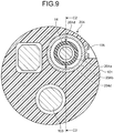
- FIG. 9 is a cross-sectional view taken along the line B2-B2 of FIG. 8 .
- the cross-section of FIG. 8 is a cross-section corresponding to the line C2-C2 of FIG. 9 .
- the wire 204d includes two wires respectively disposed above and below the distal bending portion 204b. Then, when the distal end portion of the treatment instrument channel 204 is raised, an upper wire 204d is pulled toward the proximal end, and a lower wire 204d is pressed toward the distal end in cooperation with pulling of the upper wire 204d.
- the treatment instrument channel 204 according to the second embodiment is moved smoother than the treatment instrument channel 104 of the ultrasound endoscope 2 according to the first embodiment having the single wire. Accordingly, the ultrasound endoscope according to the second embodiment can independently change a direction (projecting direction) in which the treatment instrument 14 projects from the treatment instrument channel 204, and the observation directions of the imaging unit 106 and the ultrasound transducer unit 102.
- the wire 204d is more suitable for transmission of pulling operation than for transmission of pressing operation, and, in particular, the ultrasound endoscope according to the second embodiment can provide smoother falling operation than an ultrasound endoscope having one wire.
- the upper wire 204d and the lower wire 204d may have configurations cooperating with each other, but may have configurations for independent movement.
- the distal bending portion 204b, the wires 204d, and the like having a function of raising the treatment instrument 14 are coated for water tightness by the bending rubber 204f. That is, the distal end portion of the treatment instrument channel 204 is coated for water tightness, and has a bendable configuration. Accordingly, in the ultrasound endoscope according to the second embodiment, a portion having no water tightness and required to be cleaned has no complicated configuration, and the ultrasound endoscope has improved cleaning efficiency. Accordingly, the ultrasound endoscope according to the present second embodiment is an endoscope having improved cleaning efficiency.
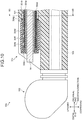
- FIG. 10 is a schematic view illustrating a configuration of a main portion of an ultrasound diagnostic system which includes an ultrasound endoscope according to a third embodiment of the present invention. Except for a configuration of a distal end portion of a treatment instrument channel 304, the ultrasound endoscope according to the third embodiment has the same configuration as that of the ultrasound endoscope 2 according to the first embodiment, and description of the same configuration will be omitted appropriately.
- the distal end portion of the treatment instrument channel 304 includes a treatment instrument insertion passage 304a communicating with the treatment instrument insertion opening 11b of the operating unit 11, a distal bending portion 304b disposed on an outer periphery of the distal end of the treatment instrument insertion passage 304a, a distal end member 304c disposed at a distal end in an insertion direction of the treatment instrument insertion passage 304a, a wire 304d disposed along the insertion direction and connected to the distal end member 304c, a bending rubber 304f as a coating portion covering the distal bending portion 304b and the wire 304d for water tightness through a braid 304e, and an O-ring 304g sealing between the distal rigid portion 101 and the distal bending portion 304b to ensure water tightness.
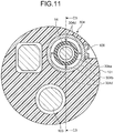
- FIG. 11 is a cross-sectional view taken along the line B3-B3 of FIG. 10 .
- the cross-section of FIG. 10 is a cross-section corresponding to the line C3-C3 of FIG. 11 .
- the wire 304d includes four wires respectively disposed above and below, and to the right and left of the distal bending portion 304b.
- FIG. 12 is a diagram illustrating a structure of the distal bending portion of FIG. 10 .
- the distal bending portion 304b includes a tubular member 304ba having an integrated configuration having connection portions 304bb in a horizontal direction (back and forth direction in the drawing of FIG. 12 ), and connection portions 304bc in a vertical direction.
- the tubular member 304ba has gaps 304bd each positioned above the corresponding connection portion 304bb and having a width decreasing downward, and gaps 304be each located below the corresponding connection portion 304bb and having a constant width.
- the tubular member 304ba has gaps 304bf each having a width decreasing toward the corresponding connection portion 304bc.
- the distal end portion of the treatment instrument channel 304 allows raising movement of the treatment instrument 14 using the wires 304d vertically located, and horizontal movement of the treatment instrument 14 using the wires 304d horizontally located. Accordingly, the ultrasound endoscope according to the present third embodiment can change the projecting direction of the treatment instrument 14, independently of the observation direction of the endoscope.
- the ultrasound endoscope according to the present third embodiment has a function unavailable from a conventional treatment instrument raiser, for example, a function for adjusting a horizontal position of the treatment instrument 14 upon puncture of a puncture needle inserted into the treatment instrument channel 304 to a region of interest of a subject.
- the distal bending portion 304b, the wires 304d, and the like having a function of raising the treatment instrument 14 are coated for water tightness by the bending rubber 304f. That is, the distal end portion of the treatment instrument channel 304 is coated for water tightness, and has a bendable configuration. Accordingly, in the ultrasound endoscope according to the third embodiment, a portion having no water tightness and required to be cleaned has no complicated configuration, and the ultrasound endoscope has improved cleaning efficiency. Accordingly, the ultrasound endoscope according to the present third embodiment is an endoscope having improved cleaning efficiency.
- the structure of the distal bending portion is not particularly limited.
- such an articulated ring structure as illustrated in FIG. 5 may be used for the distal bending portion 304b.
- the one wire first embodiment
- two wires second embodiment
- four wires third embodiment
- the number of wires is not particularly limited.
- the endoscope employs, for description, an oblique-viewing endoscope in which the imaging unit has an oblique observation direction, but the endoscope is not limited to the oblique-viewing endoscope.
- a forward-viewing endoscope performing observation in a direction along an insertion direction, or a side-viewing endoscope performing observation in a direction orthogonal to an insertion direction may be employed.
- the configurations according to the embodiments described above can be also applied to change the projecting direction of the treatment instrument 14, independently of the observation direction of the endoscope.
Landscapes
- Health & Medical Sciences (AREA)
- Life Sciences & Earth Sciences (AREA)
- Surgery (AREA)
- Physics & Mathematics (AREA)
- General Health & Medical Sciences (AREA)
- Molecular Biology (AREA)
- Pathology (AREA)
- Radiology & Medical Imaging (AREA)
- Nuclear Medicine, Radiotherapy & Molecular Imaging (AREA)
- Engineering & Computer Science (AREA)
- Biomedical Technology (AREA)
- Heart & Thoracic Surgery (AREA)
- Medical Informatics (AREA)
- Veterinary Medicine (AREA)
- Animal Behavior & Ethology (AREA)
- Biophysics (AREA)
- Public Health (AREA)
- Optics & Photonics (AREA)
- Astronomy & Astrophysics (AREA)
- General Physics & Mathematics (AREA)
- Endoscopes (AREA)
- Ultra Sonic Daignosis Equipment (AREA)
Applications Claiming Priority (2)
| Application Number | Priority Date | Filing Date | Title |
|---|---|---|---|
| JP2015123095 | 2015-06-18 | ||
| PCT/JP2016/068008 WO2016204252A1 (ja) | 2015-06-18 | 2016-06-16 | 内視鏡 |
Publications (2)
| Publication Number | Publication Date |
|---|---|
| EP3311751A1 true EP3311751A1 (de) | 2018-04-25 |
| EP3311751A4 EP3311751A4 (de) | 2019-06-05 |
Family
ID=57546207
Family Applications (1)
| Application Number | Title | Priority Date | Filing Date |
|---|---|---|---|
| EP16811726.5A Withdrawn EP3311751A4 (de) | 2015-06-18 | 2016-06-16 | Endoskop |
Country Status (5)
| Country | Link |
|---|---|
| US (1) | US10172511B2 (de) |
| EP (1) | EP3311751A4 (de) |
| JP (1) | JP6104492B1 (de) |
| CN (1) | CN107106135B (de) |
| WO (1) | WO2016204252A1 (de) |
Families Citing this family (5)
| Publication number | Priority date | Publication date | Assignee | Title |
|---|---|---|---|---|
| WO2019146330A1 (ja) * | 2018-01-26 | 2019-08-01 | 富士フイルム株式会社 | 内視鏡 |
| CN110384520A (zh) * | 2018-04-18 | 2019-10-29 | 深圳开立生物医疗科技股份有限公司 | 超声波成像系统及其导管 |
| CN109044248B (zh) * | 2018-06-29 | 2021-02-19 | 华南师范大学 | 基于蛇骨变向的弯曲腔体内三维光声内窥镜及其成像方法 |
| CN110141178A (zh) * | 2019-05-30 | 2019-08-20 | 深圳开立生物医疗科技股份有限公司 | 内窥镜头端座及内窥镜 |
| JP7830503B2 (ja) * | 2021-04-06 | 2026-03-16 | ボストン サイエンティフィック サイムド,インコーポレイテッド | 体管腔内に医療デバイスを配置するためのデバイス、システム、および方法 |
Family Cites Families (12)
| Publication number | Priority date | Publication date | Assignee | Title |
|---|---|---|---|---|
| GB2161389B (en) * | 1984-07-05 | 1988-06-08 | Wolf Gmbh Richard | Instrument insert for a uretero-renoscope |
| US5343853A (en) * | 1991-09-20 | 1994-09-06 | Fuji Photo Optical Co., Ltd. | Side-looking type electronic endoscope which allows manipulating tool to be inserted thereinto |
| JP3124079B2 (ja) * | 1991-11-06 | 2001-01-15 | 旭光学工業株式会社 | 内視鏡の処置具起上装置 |
| US5460168A (en) * | 1992-12-25 | 1995-10-24 | Olympus Optical Co., Ltd. | Endoscope cover assembly and cover-system endoscope |
| JP3212788B2 (ja) * | 1993-12-27 | 2001-09-25 | オリンパス光学工業株式会社 | 内視鏡 |
| JP3207991B2 (ja) * | 1993-12-27 | 2001-09-10 | オリンパス光学工業株式会社 | 内視鏡カバー方式の内視鏡装置 |
| JPH08215140A (ja) * | 1995-02-10 | 1996-08-27 | Olympus Optical Co Ltd | 内視鏡装置 |
| JP2000116598A (ja) | 1998-10-19 | 2000-04-25 | Toshiba Corp | 内視鏡装置 |
| US7815564B2 (en) * | 2006-02-21 | 2010-10-19 | Boston Scientific Scimed, Inc. | Positioning system for manipulating a channel within a medical device |
| US20070265494A1 (en) * | 2006-05-10 | 2007-11-15 | Boston Scientific Scimed Inc. | Flexible and retractable endoscope elevator |
| JP4847354B2 (ja) * | 2007-01-22 | 2011-12-28 | オリンパスメディカルシステムズ株式会社 | 内視鏡用処置具 |
| US20110112365A1 (en) * | 2009-06-03 | 2011-05-12 | Gyrus Acmi, Inc. | Endoscope shaft |
-
2016
- 2016-06-16 EP EP16811726.5A patent/EP3311751A4/de not_active Withdrawn
- 2016-06-16 CN CN201680004653.4A patent/CN107106135B/zh active Active
- 2016-06-16 WO PCT/JP2016/068008 patent/WO2016204252A1/ja not_active Ceased
- 2016-06-16 JP JP2017502728A patent/JP6104492B1/ja active Active
-
2017
- 2017-06-06 US US15/614,865 patent/US10172511B2/en active Active
Also Published As
| Publication number | Publication date |
|---|---|
| CN107106135B (zh) | 2020-02-28 |
| JP6104492B1 (ja) | 2017-03-29 |
| CN107106135A (zh) | 2017-08-29 |
| US10172511B2 (en) | 2019-01-08 |
| EP3311751A4 (de) | 2019-06-05 |
| US20170265718A1 (en) | 2017-09-21 |
| WO2016204252A1 (ja) | 2016-12-22 |
| JPWO2016204252A1 (ja) | 2017-06-29 |
Similar Documents
| Publication | Publication Date | Title |
|---|---|---|
| JP5153476B2 (ja) | 内視鏡装置 | |
| CN211985382U (zh) | 一种输尿管肾盂镜系统 | |
| US10172511B2 (en) | Endoscope | |
| EP3656276B1 (de) | Endoskop | |
| US11992187B2 (en) | Endoscope | |
| US20190008369A1 (en) | Endoscope | |
| WO2017002417A1 (ja) | 超音波観測装置、超音波観測装置の作動方法および超音波観測装置の作動プログラム | |
| JP4300378B2 (ja) | 分離可能型超音波内視鏡 | |
| JP3671763B2 (ja) | 内視鏡着脱型超音波検査装置 | |
| JP7592548B2 (ja) | 超音波内視鏡 | |
| US12605050B2 (en) | Endoscopic device and methods of use thereof | |
| JP2009028109A (ja) | 超音波内視鏡 | |
| EP3656281B1 (de) | Endoskop | |
| CN113413115B (zh) | 旋钮组件、操作部及电子内窥镜 | |
| JP3671764B2 (ja) | 内視鏡着脱型電子走査式超音波検査装置 | |
| JP7628831B2 (ja) | 超音波内視鏡 | |
| JP2014138668A (ja) | 内視鏡および固定方法 | |
| JP3766644B2 (ja) | 内視鏡および内視鏡用フード部材 | |
| JP5893508B2 (ja) | 内視鏡 | |
| JP2012213572A (ja) | 内視鏡用補助観察装置 | |
| JP2001095796A (ja) | 分離可能型超音波内視鏡 | |
| JP2009183380A (ja) | 検診用内視鏡 | |
| JP2019041884A (ja) | 超音波内視鏡 | |
| JP2014087489A (ja) | 内視鏡アダプタ | |
| WO2018230502A1 (ja) | 超音波内視鏡 |
Legal Events
| Date | Code | Title | Description |
|---|---|---|---|
| STAA | Information on the status of an ep patent application or granted ep patent |
Free format text: STATUS: THE INTERNATIONAL PUBLICATION HAS BEEN MADE |
|
| PUAI | Public reference made under article 153(3) epc to a published international application that has entered the european phase |
Free format text: ORIGINAL CODE: 0009012 |
|
| STAA | Information on the status of an ep patent application or granted ep patent |
Free format text: STATUS: REQUEST FOR EXAMINATION WAS MADE |
|
| 17P | Request for examination filed |
Effective date: 20180116 |
|
| AK | Designated contracting states |
Kind code of ref document: A1 Designated state(s): AL AT BE BG CH CY CZ DE DK EE ES FI FR GB GR HR HU IE IS IT LI LT LU LV MC MK MT NL NO PL PT RO RS SE SI SK SM TR |
|
| AX | Request for extension of the european patent |
Extension state: BA ME |
|
| DAV | Request for validation of the european patent (deleted) | ||
| DAX | Request for extension of the european patent (deleted) | ||
| RIC1 | Information provided on ipc code assigned before grant |
Ipc: A61B 1/00 20060101ALI20190125BHEP Ipc: A61B 8/12 20060101AFI20190125BHEP |
|
| A4 | Supplementary search report drawn up and despatched |
Effective date: 20190506 |
|
| RIC1 | Information provided on ipc code assigned before grant |
Ipc: A61B 8/12 20060101AFI20190429BHEP Ipc: A61B 1/00 20060101ALI20190429BHEP |
|
| STAA | Information on the status of an ep patent application or granted ep patent |
Free format text: STATUS: THE APPLICATION IS DEEMED TO BE WITHDRAWN |
|
| 18D | Application deemed to be withdrawn |
Effective date: 20191203 |