EP3311772A1 - Gesamtheit der elemente zur herstellung einer zahnprothese - Google Patents
Gesamtheit der elemente zur herstellung einer zahnprothese Download PDFInfo
- Publication number
- EP3311772A1 EP3311772A1 EP17194927.4A EP17194927A EP3311772A1 EP 3311772 A1 EP3311772 A1 EP 3311772A1 EP 17194927 A EP17194927 A EP 17194927A EP 3311772 A1 EP3311772 A1 EP 3311772A1
- Authority
- EP
- European Patent Office
- Prior art keywords
- assembly
- master model
- intended
- dental
- prosthesis
- Prior art date
- Legal status (The legal status is an assumption and is not a legal conclusion. Google has not performed a legal analysis and makes no representation as to the accuracy of the status listed.)
- Granted
Links
Images


Classifications
-
- A—HUMAN NECESSITIES
- A61—MEDICAL OR VETERINARY SCIENCE; HYGIENE
- A61C—DENTISTRY; APPARATUS OR METHODS FOR ORAL OR DENTAL HYGIENE
- A61C13/00—Dental prostheses; Making same
- A61C13/0003—Making bridge-work, inlays, implants or the like
- A61C13/0004—Computer-assisted sizing or machining of dental prostheses
-
- A—HUMAN NECESSITIES
- A61—MEDICAL OR VETERINARY SCIENCE; HYGIENE
- A61C—DENTISTRY; APPARATUS OR METHODS FOR ORAL OR DENTAL HYGIENE
- A61C13/00—Dental prostheses; Making same
- A61C13/0003—Making bridge-work, inlays, implants or the like
- A61C13/0006—Production methods
- A61C13/0019—Production methods using three dimensional printing
-
- A—HUMAN NECESSITIES
- A61—MEDICAL OR VETERINARY SCIENCE; HYGIENE
- A61C—DENTISTRY; APPARATUS OR METHODS FOR ORAL OR DENTAL HYGIENE
- A61C13/00—Dental prostheses; Making same
- A61C13/34—Making or working of models, e.g. preliminary castings, trial dentures; Dowel pins [4]
-
- A—HUMAN NECESSITIES
- A61—MEDICAL OR VETERINARY SCIENCE; HYGIENE
- A61C—DENTISTRY; APPARATUS OR METHODS FOR ORAL OR DENTAL HYGIENE
- A61C13/00—Dental prostheses; Making same
- A61C13/0001—In-situ dentures; Trial or temporary dentures
-
- A—HUMAN NECESSITIES
- A61—MEDICAL OR VETERINARY SCIENCE; HYGIENE
- A61C—DENTISTRY; APPARATUS OR METHODS FOR ORAL OR DENTAL HYGIENE
- A61C13/00—Dental prostheses; Making same
- A61C13/0003—Making bridge-work, inlays, implants or the like
- A61C13/0006—Production methods
- A61C13/0013—Production methods using stereolithographic techniques
-
- A—HUMAN NECESSITIES
- A61—MEDICAL OR VETERINARY SCIENCE; HYGIENE
- A61C—DENTISTRY; APPARATUS OR METHODS FOR ORAL OR DENTAL HYGIENE
- A61C13/00—Dental prostheses; Making same
- A61C13/08—Artificial teeth; Making same
-
- A—HUMAN NECESSITIES
- A61—MEDICAL OR VETERINARY SCIENCE; HYGIENE
- A61C—DENTISTRY; APPARATUS OR METHODS FOR ORAL OR DENTAL HYGIENE
- A61C8/00—Means to be fixed to the jaw-bone for consolidating natural teeth or for fixing dental prostheses thereon; Dental implants; Implanting tools
- A61C8/0001—Impression means for implants, e.g. impression coping
-
- A—HUMAN NECESSITIES
- A61—MEDICAL OR VETERINARY SCIENCE; HYGIENE
- A61C—DENTISTRY; APPARATUS OR METHODS FOR ORAL OR DENTAL HYGIENE
- A61C8/00—Means to be fixed to the jaw-bone for consolidating natural teeth or for fixing dental prostheses thereon; Dental implants; Implanting tools
- A61C8/0018—Means to be fixed to the jaw-bone for consolidating natural teeth or for fixing dental prostheses thereon; Dental implants; Implanting tools characterised by the shape
- A61C8/0027—Frames
-
- A—HUMAN NECESSITIES
- A61—MEDICAL OR VETERINARY SCIENCE; HYGIENE
- A61C—DENTISTRY; APPARATUS OR METHODS FOR ORAL OR DENTAL HYGIENE
- A61C8/00—Means to be fixed to the jaw-bone for consolidating natural teeth or for fixing dental prostheses thereon; Dental implants; Implanting tools
- A61C8/0048—Connecting the upper structure to the implant, e.g. bridging bars
- A61C8/005—Connecting devices for joining an upper structure with an implant member, e.g. spacers
- A61C8/0068—Connecting devices for joining an upper structure with an implant member, e.g. spacers with an additional screw
-
- A—HUMAN NECESSITIES
- A61—MEDICAL OR VETERINARY SCIENCE; HYGIENE
- A61C—DENTISTRY; APPARATUS OR METHODS FOR ORAL OR DENTAL HYGIENE
- A61C9/00—Impression cups, i.e. impression trays; Impression methods
- A61C9/004—Means or methods for taking digitized impressions
- A61C9/0046—Data acquisition means or methods
-
- B—PERFORMING OPERATIONS; TRANSPORTING
- B33—ADDITIVE MANUFACTURING TECHNOLOGY
- B33Y—ADDITIVE MANUFACTURING, i.e. MANUFACTURING OF THREE-DIMENSIONAL [3D] OBJECTS BY ADDITIVE DEPOSITION, ADDITIVE AGGLOMERATION OR ADDITIVE LAYERING, e.g. BY 3D PRINTING, STEREOLITHOGRAPHY OR SELECTIVE LASER SINTERING
- B33Y10/00—Processes of additive manufacturing
Definitions
- the present invention relates to the field of dental prosthetic restoration, and more particularly relates to the manufacture of an assembly comprising a master model manufactured by an additive technology such as a 3D printing (also called "three-dimensional printing").
- the master model is a representation of at least a part of the oral cavity of the patient to be restored by the prosthesis to be manufactured.
- the prosthetist uses it to prepare a prosthesis exactly sized to conform to the dentition of the patient.
- the master models are made from a survey of the intraoral geometry of a patient. Traditionally, the master models were made of plaster from impressions of the dentition of the patient, made by means of a dental paste arranged in impression trays generally U-shaped. a teething restoration by means of one or more dental implants, the master-model comprises one or more implant analogs positioned and oriented so as to exactly reproduce the position of the implant (s) in the patient's mouth.
- the dental prosthetic element blanks are each attached to the master model by an externally threaded fixing screw which is screwed into a tapped bore of the implant analog.
- Three-dimensional intra-oral scanning process makes it possible to perform a survey of the patient's intra-oral geometry by avoiding impression taking using impression trays, whose accuracy depended heavily on dexterity. of the dentist taking the impression.
- Three-dimensional intra-oral scanning provides three-dimensional computer modeling of the patient's dentition, which the prosthetist will then use to design the prosthesis.
- Three-dimensional computer modeling of the patient's dentition is then used to make the master model by a material addition manufacturing process (additive technology such as 3D printing).
- additive technology such as 3D printing
- a 3D printer "prints" the master model by stacking a succession of thin layers of material (strata).
- cavities are provided for precisely receiving and indexed implant analogs reported, as described in the documents US 2011/029093 A1 , US 2015/0374466 A1 , US 2016/0135931 A1 , WO 2014/139498 A1 and WO 2014/161552 A2 .
- adjacent implants may have to be placed in the patient's mouth in the immediate vicinity of each other and with angulations between them which make it impossible to reproduce them by means of implant analogs in a master model.
- a problem proposed by the present invention is to manufacture a master model by additive technology by means of a disposition of material in successive layers, such as 3D printing, at a reduced cost while reducing the risk of inaccuracy.
- Another problem proposed by the invention is to provide reliable holding of the prosthesis on the master model during the development of the prosthesis by the prosthetist.
- the master model is made from a survey of the oral geometry of a patient having at least one dental implant having a reference surface.
- the reference surface of the model master corresponds to the reference surface of said dental implant, and can therefore receive by direct support the dental prosthetic element.
- the master model is devoid of an implant analogue, since the thread intended to receive the fixing screw is directly printed during the manufacture of the master model.
- the reference surfaces for the reception (by direct contact) of the dental prosthetic element (such as a prosthesis, such as a transfixed multiple prosthesis reinforcement type, or such as a dental abutment) are also directly produced by 3D printing. .
- the cost of the master model is thus greatly reduced, and there is no longer any risk of conflict between adjacent implant analogues.
- the pitch and thread height parameters of the thread of the fastening screw provide the thread with sufficient dimensions, relative to the thickness of the layers, for the internal threading of the threaded cavity to receive the fastening screw reliably and accurately. and ensures a satisfactory restraint.
- the profile of the thread of the fixing screw (temporary) in the master model may be different from the thread profile of the threaded cavity of the implant in the patient's mouth, so that this fixing screw can not be then engaged and / or retained by screwing into the threaded cavity of the implant into patient's mouth.
- the fixation screw of the prosthesis on the master model can then be made of a non-biocompatible material, in order to reduce costs, and is used exclusively for fixing the dental prosthetic element on the master model, while a different screw will be used to fix the dental prosthetic element on the dental implant in the patient's mouth.
- the external thread of the fixing screw may have a profile that is not metric.
- a metric profile would require, to respect the parameters set by the present invention, to use layers of too small thickness. This would greatly increase the 3D printing time and therefore the cost of obtaining the master model.
- the threaded cavity of the implant in the patient's mouth is generally provided with a metric profile thread.
- an external screw thread that is not metric prevents reuse in most implants in the mouth for the final fixation of the prosthesis.
- the external thread of the fixing screw may have a trapezoidal profile.
- the threads thus have no sharp edge at their top, which limits the risk of degradation of the internal thread of the threaded cavity in which the fastening screw is inserted several times during the manufacture of the prosthesis.
- the fixing screw and the threaded cavity may be shaped so that, during the attachment of a dental prosthetic element to the master model, the fixing screw is engaged in the internal thread in at least four steps.
- a four-step engagement proved sufficient to limit the risk of degradation of the internal thread of the threaded cavity when tightening the fastening screw. This prevents the constituent material of the internal thread of the threaded cavity (a plastic generally) is plastically deformed or even accidentally torn off.
- a transfixed plural prosthetic armature is generally used to restore partially or completely a dental arch. It is usually carried in the patient's mouth by several implants lying in directions not parallel to each other (oblique).
- the excrescences with a distal section intended to engage at least partially in corresponding hollow housings formed in said transfixed plural prosthesis armature allow precise positioning of the plural prosthesis armature on the master model.
- the hollow housings intended to receive at least in part the distal section of corresponding excrescences carried by said transfixed plural prosthesis reinforcement allow precise positioning of the plural prosthesis reinforcement on the master model.
- Each distal section outgrowth provided on its outer surface with a lateral recess (for example by means of a frustoconical outer shape) cooperates with the corresponding hollow housing (possibly provided on its inner surface with a lateral recess, for example by means of of a frustoconical inner shape) of the transfixed plural prosthesis reinforcement to carry out a gradual and precise centering of the prosthetic reinforcement on each of the excrescences.
- the external lateral relief of the growths makes it possible to facilitate the engagement of the transfixed multiple prosthesis reinforcement on the growths, particularly when the growths develop in respective axial directions that are oblique to each other.
- the false gum allows the prosthetist to ensure the aesthetics of the prosthetic restoration he prepares, including ensuring that the junction area between the prosthesis and the implant will be well hidden by the gum.
- each protrusion section provided on its outer surface with a lateral recess (for example by means of a frustoconical outer shape) cooperates with the corresponding hollow housing (possibly provided on its inner surface with a lateral recess, by example by means of a frustoconical inner shape) of the false gum to carry out a gradual and precise centering of the false gum on each of the growths.
- the external lateral relief of the growths facilitates the engagement of the false gum on the growths, particularly when the growths develop in respective axial directions which are oblique to each other.
- the master model thus comprises a connector adapted for accurate reception of the unitary dental abutment pillar, this connection being directly printed during the manufacture of the master model.
- Said cavity hollow connection may comprise a non-circular cross section, the pillar can thus be indexed in rotation relative to the master model.
- the false gum allows the prosthetist to ensure the estheticism of the prosthetic restoration he prepares, especially by checking that the junction area between the prosthesis (or the prosthesis pillar) and the implant will be well hidden by the gums.
- each protuberance provided on its outer surface with a lateral recess (for example by means of a frustoconical outer shape) cooperates with the corresponding hollow housing (possibly provided on its inner surface with a lateral recess, for example by means of a frustoconical inner shape) of the false gum to proceed to a gradual and precise centering of the false gum on the protuberance.
- a method for manufacturing a master model for making a dental prosthesis from a three-dimensional computer modeling computer file of the dentition to be restored from the patient from intra-oral scanning of the patient's oral cavity comprises a step in which one includes, in the three-dimensional computer modeling, at least one reference surface intended to be made during the manufacture of the master model by additive technology and corresponding to a reference surface. a dental implant in the patient's mouth.
- a master model manufactured by an additive technology, such as a 3D printing, said master model comprising at least one reference surface intended to support a dental prosthetic element. , said reference surface being made during the manufacture of the master model by additive technology and corresponding to a reference surface of a dental implant disposed in the patient's mouth.
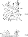
- FIG. 1 to 18 two particular embodiments of assemblies 1 according to the invention are illustrated. A first embodiment is illustrated on the Figures 1 to 9 while a second embodiment is illustrated on the Figures 10 to 17 .
- the assembly 1 for the preparation of a dental prosthesis comprises a master model 2 manufactured by an additive technology by means of a material arrangement in successive layers 3 (see FIG. figure 9 ), such as 3D printing.
- Master Model 2 is made from intraoral scanning.
- the assembly 1 further comprises at least one fastening screw 4 with external thread 4a, intended to removably attach to the master model 2 a dental prosthetic element 5.
- Two fixing screws 4 specific to each of the embodiments , are illustrated on Figures 7 and 8 on the one hand, and on Figures 16 and 17 on the other hand. These fastening screws 4 are identical with respect to their external thread 4a, and differ substantially only in the shape of their head 4b in which is formed a hexagonal hollow cavity 4c drive in rotation.
- the master model 2 comprises at least one reference surface S intended to receive the dental prosthetic element 5 in abutment, said reference surface S being produced during the manufacture of the master model 2 by additive technology.
- the master model 2 comprises at least one threaded cavity 6 whose internal thread 6a, intended to receive said fixing screw 4 by screwing, is produced during the manufacture of the master model 2 by additive technology (see FIG. Figures 1 to 6 and Figures 10 to 15 ).
- the external thread 4a of the fixing screw 4 does not have a metric profile.
- the external thread 4a of the fixing screw 4 has a trapezoidal profile, so that the fixing screw 4 can not be received in dental implants which generally have a metric profile internal thread.
- the fixing screw 4 is made of a cheap metal material, and does not need to be biocompatible since it is not able to be received by screwing into a dental implant in the patient's mouth.
- the fixing screw 4 and the threaded cavity 6 are shaped so that, during the attachment of a dental prosthetic element 5 to the master model 2, the fixing screw 4 is engaged in the internal threading 6a according to at least four steps, as illustrated on the figure 9 .
- the assembly 1 is associated with a dental prosthetic element 5 of type transfixed plural prosthesis frame 7.
- This transfixed plural prosthetic armature 7 is intended to be attached to a plurality of implants in the patient's mouth (four in the present case ). There are thus provided several (four) threaded cavities 6 representative of the implants as they are positioned in the mouth of the patient.
- Each threaded cavity 6 is formed in an outgrowth 8 with a distal section 8a of frustoconical outer shape, said distal section 8a being intended to engage at least partly in a corresponding frustoconical housing 7a formed in said transfixed plural prosthesis armature 7, as it is more particularly visible on the figure 6 .
- the protuberances 8 situated at the rear of the master model 2 develop in respective axial directions which are oblique with respect to the respective axial directions in which the protrusions 8 situated in the anterior part of the master-model 2 develop.
- This oblique arrangement results from orientations of the threaded cavities 6 which are themselves in the image of the orientations of the implants in the patient's mouth.
- the assembly 1 further comprises a false gingiva 9 intended to be attached to the master model 2.
- Each protrusion 8 comprises a proximal section 8b of frustoconical outer shape intended to engage at least partly in a corresponding frustoconical housing 9a. formed in said false gum 9, as it is more particularly visible on the figures 4 and 6 .
- the master model 2 comprises a reference surface S substantially in the form of a ring.
- This reference surface S corresponds exactly (in dimensions, position and orientation) to the reference surface carried by the implant in the mouth against which is intended to bear the transfixed plural prosthesis armature 7.
- the prosthetist can thus design his prosthesis on the transfixed plural prosthesis frame 7 taking into account the nearby teeth (which are the teeth of the opposing dental arch) for the contact areas and occlusion points.
- the assembly 1 is associated with a dental prosthetic element 5 pillar type 10 unitary dental prosthesis.
- a hollow connection socket 11 is provided at the mouth of the threaded cavity 6.
- the hollow cavity of connection 11 comprises a reference surface S which corresponds exactly (in dimensions, position and orientation) to the reference surface of the hollow impression of the implant in the mouth in which the pillar is intended to be received. 10.
- the prosthetist can thus design his prosthesis by sticking it on the pillar 10 taking into account the teeth located nearby (which are here the adjacent teeth D1 and D2 non-prosthetic teeth and the teeth of the opposing dental arch) for the contact areas and occlusion points.
- the hollow connection footprint 11 has a non-circular cross-section to index the pillar 10 in rotation.
- the cross section of the hollow connection footprint 11 has a triangular shape which is complementary to the lower end of the pillar 10.
- the assembly 1 further comprises a false gum 12 intended to be reported on the master model 2. More specifically, it is observed on the Figures 10, 11 and 13 that, at the mouth of the hollow connection socket 11 is provided a frustoconical protrusion 13, intended to engage at least partly in a corresponding frustoconical housing 12a formed in said false gum 12.
- a set 1 During the manufacture of a set 1 according to the invention, it is first of all carried out by the dental surgeon to an intra-oral scan of the dentition to be restored to the patient.
- This intra-oral scan can generate a three-dimensional computer modeling of the dentition to restore the patient.
- the computer file resulting from the intra-oral scanning is then reworked by computer to include reference surfaces corresponding to the reference surface (s) worn by the implant (or implants) arranged (s). in the patient's mouth.
- Computer-aided manufacturing of the master model 2 is then carried out by additive technology by means of a material arrangement in successive layers, such as 3D printing.
- a 3D printer prints master model 2 by stacking a succession of thin layers of material (or layers) 3 of thickness E.
- the reference surface (s) S of the hollow fingerprint (s) of the connection (s) 11 or, if appropriate, of the protrusion (s) 8 or protuberance (s) 13, is ( are) also realized by 3D printing.
- the prosthetist can engage the false gum 9 ( Figures 3 and 4 ) or 12 ( Figures 12 and 13 ) on the protuberances 8 or protrusion (s) 13.
- the false gums 9 or 12 engage according to their (s) housing (s) frustoconical (s) 9a or 12a on the proximal sections 8b or protuberance (s) 13 of the master -model 2.
- the prosthetist then places the transfixed plural prosthesis armature 7 on the reference surfaces S toward which the transfixed plural prosthesis armature 7 is progressively guided by means of the frustoconical distal sections 8a. Then the prosthetist inserts the screws 4 in the threaded cavities 6 and the screws to fix the transfixed plural prosthesis armature 7 on the master model 2 ( Figures 5 and 6 ).
- the prosthetist then inserts the abutment 10 in the hollow cavity of connection 11. Then the prosthetist inserts the fixing screw 4 in the threaded cavity 6 and screws it to fix the pillar 10 on the master -model 2 ( Figures 14 and 15 ).
- the fixing screws 4 are engaged in the internal thread 6a in at least four steps P.
- the prosthetist can then proceed to the manufacture, adjustment or control of his dental prosthetic element (for example a transfixed plural prosthesis 7 in the case of the first embodiment, or a dental piercing unitary transfixed prosthesis 10 in the case of second embodiment) in the same way as with the "classic" master models in plaster.
- his dental prosthetic element for example a transfixed plural prosthesis 7 in the case of the first embodiment, or a dental piercing unitary transfixed prosthesis 10 in the case of second embodiment
- the dental prosthetic element 7 or 10 After the manufacture, adjustment or control of the dental prosthetic element 7 or 10, the latter will be attached and fixed on the dental implant in the patient's mouth with the aid of another screw (which may be called final fixing screw). Indeed, the profile of the external thread 4a of the fixing screw 4 is different from the internal thread profile of the implant in the patient's mouth, so that this fixing screw 4 can not then be engaged and / or retained by screwing into the threaded cavity of the implant in the patient's mouth.
- the protuberances 8, the protuberances 13 and the recesses 7a, 9a, 12a hollow are frustoconical.
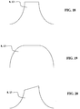
- the protuberances 8 and the protuberances 13 may nevertheless have different external shapes, also provided with a lateral relief providing a gradual decrease in their cross-section, as illustrated in FIGS. Figures 18 to 20 which are side views of protuberances 8 or protuberances 13.
- Hollow recesses 7a, 9a, 12a may also have internal shapes other than frustoconical shapes, for example complementary to the shapes illustrated in FIGS. Figures 18 to 20 .
- an independent protection by patent can be sought for a master model 2 manufactured by an additive technology, such as a 3D printing, said master model 2 comprising at least one reference surface S intended to receive in supporting (direct) a dental prosthetic element (transfixed plural prosthesis reinforcement 7, unitary dental prosthesis pillar 10, etc.), said reference surface S being made during the manufacture of the master model 2 by additive technology and corresponding to a surface reference of a dental implant disposed in the patient's mouth.
- This protection can be sought regardless of the presence and the parameters of fixing screw 4 and threaded cavity (s) 6.
- the problem solved by this combination of features is to manufacture a master model by additive technology by means of an arrangement of material in successive layers, such as 3D printing, at a reduced cost while reducing the risk of inaccuracy.
Landscapes
- Health & Medical Sciences (AREA)
- Oral & Maxillofacial Surgery (AREA)
- Dentistry (AREA)
- Epidemiology (AREA)
- Life Sciences & Earth Sciences (AREA)
- Animal Behavior & Ethology (AREA)
- General Health & Medical Sciences (AREA)
- Public Health (AREA)
- Veterinary Medicine (AREA)
- Engineering & Computer Science (AREA)
- Manufacturing & Machinery (AREA)
- Orthopedic Medicine & Surgery (AREA)
- Chemical & Material Sciences (AREA)
- Materials Engineering (AREA)
- Dental Prosthetics (AREA)
Applications Claiming Priority (1)
| Application Number | Priority Date | Filing Date | Title |
|---|---|---|---|
| FR1660123A FR3057458B1 (fr) | 2016-10-19 | 2016-10-19 | Ensemble pour la preparation d'une prothese dentaire |
Publications (2)
| Publication Number | Publication Date |
|---|---|
| EP3311772A1 true EP3311772A1 (de) | 2018-04-25 |
| EP3311772B1 EP3311772B1 (de) | 2020-02-26 |
Family
ID=57796548
Family Applications (1)
| Application Number | Title | Priority Date | Filing Date |
|---|---|---|---|
| EP17194927.4A Active EP3311772B1 (de) | 2016-10-19 | 2017-10-05 | Gesamtheit der elemente zur herstellung einer zahnprothese |
Country Status (7)
| Country | Link |
|---|---|
| US (1) | US10624723B2 (de) |
| EP (1) | EP3311772B1 (de) |
| JP (1) | JP7068795B2 (de) |
| CN (1) | CN107961092B (de) |
| BR (1) | BR102017022538A2 (de) |
| FR (1) | FR3057458B1 (de) |
| RU (1) | RU2744713C2 (de) |
Cited By (1)
| Publication number | Priority date | Publication date | Assignee | Title |
|---|---|---|---|---|
| EP3494923A1 (de) * | 2017-12-05 | 2019-06-12 | Tech Xika PTT, S.L. | Mundhöhlenmodell und herstellungsverfahren |
Citations (8)
| Publication number | Priority date | Publication date | Assignee | Title |
|---|---|---|---|---|
| US20110029093A1 (en) | 2001-05-25 | 2011-02-03 | Ray Bojarski | Patient-adapted and improved articular implants, designs and related guide tools |
| KR20130038101A (ko) * | 2011-10-08 | 2013-04-17 | 이영종 | 멀티 프로젝션을 이용한 고해상도 치아 모델 제작용 3차원 프린터 |
| US20130216980A1 (en) | 2012-02-21 | 2013-08-22 | Allen R. Boronkay | Dental models and related methods |
| WO2014139498A1 (de) | 2013-03-12 | 2014-09-18 | Spindler, Bruno | Implantatanalog und analoglagerkörper |
| WO2014161552A2 (en) | 2013-04-04 | 2014-10-09 | Elos Medtech Pinol A/S | The combination of a physical model of a set of a patient's teeth and an elongated implant analog, an elongated implant analog and a method of making a physical model of a set of teeth |
| US20150359615A1 (en) * | 2014-06-16 | 2015-12-17 | Cadent Ltd. | Unitary dental model |
| US20150374466A1 (en) | 2013-03-12 | 2015-12-31 | Nt-Trading Gmbh & Co.Kg | Implant Analog |
| US20160135931A1 (en) | 2013-12-27 | 2016-05-19 | James R. Glidewell Dental Ceramics, Inc. | Apparatus and methods of making denture devices |
Family Cites Families (12)
| Publication number | Priority date | Publication date | Assignee | Title |
|---|---|---|---|---|
| US20050023710A1 (en) * | 1998-07-10 | 2005-02-03 | Dmitri Brodkin | Solid free-form fabrication methods for the production of dental restorations |
| US6273721B1 (en) * | 1998-12-07 | 2001-08-14 | Maurice Valen | Dental implant |
| US7018207B2 (en) | 2002-02-22 | 2006-03-28 | Implant Innovations, Inc. | Dental implant analog having retention groove for soft tissue modeling |
| US8718982B2 (en) * | 2008-09-18 | 2014-05-06 | 3Shape A/S | Tools for customized design of dental restorations |
| ES2447941T3 (es) * | 2009-02-26 | 2014-03-13 | Nobel Biocare Services Ag | Conjunto de implante dental |
| DK201000730A (en) * | 2010-02-24 | 2011-08-25 | 3Shape As | Support of removable components in a teeth model manufactured by means of CAM |
| AU2012293281A1 (en) | 2011-08-10 | 2014-03-13 | Kamil Tech Ltd. | Removable dental implant bridge system |
| US8485820B1 (en) * | 2011-12-22 | 2013-07-16 | Mohamed Ikbal Ali | Devices and methods for enhancing bone growth |
| US20150173864A1 (en) * | 2012-07-12 | 2015-06-25 | Pomodent Dental, Ltd | Abutment assembly for dental implants |
| JP2014168592A (ja) | 2013-03-04 | 2014-09-18 | Akira Takebayashi | デンタルインプラント、並びに、デンタルインプラントに使用するアバットメント、締結ねじ、及び弛緩防止ねじ |
| US20180344434A1 (en) * | 2013-03-21 | 2018-12-06 | John P. POOVEY | Multi-component dental implant system |
| EP3494923A1 (de) * | 2017-12-05 | 2019-06-12 | Tech Xika PTT, S.L. | Mundhöhlenmodell und herstellungsverfahren |
-
2016
- 2016-10-19 FR FR1660123A patent/FR3057458B1/fr active Active
-
2017
- 2017-10-05 RU RU2017134990A patent/RU2744713C2/ru active
- 2017-10-05 US US15/725,368 patent/US10624723B2/en active Active
- 2017-10-05 EP EP17194927.4A patent/EP3311772B1/de active Active
- 2017-10-16 JP JP2017200083A patent/JP7068795B2/ja active Active
- 2017-10-18 CN CN201710969882.6A patent/CN107961092B/zh active Active
- 2017-10-19 BR BR102017022538-0A patent/BR102017022538A2/pt not_active Application Discontinuation
Patent Citations (8)
| Publication number | Priority date | Publication date | Assignee | Title |
|---|---|---|---|---|
| US20110029093A1 (en) | 2001-05-25 | 2011-02-03 | Ray Bojarski | Patient-adapted and improved articular implants, designs and related guide tools |
| KR20130038101A (ko) * | 2011-10-08 | 2013-04-17 | 이영종 | 멀티 프로젝션을 이용한 고해상도 치아 모델 제작용 3차원 프린터 |
| US20130216980A1 (en) | 2012-02-21 | 2013-08-22 | Allen R. Boronkay | Dental models and related methods |
| WO2014139498A1 (de) | 2013-03-12 | 2014-09-18 | Spindler, Bruno | Implantatanalog und analoglagerkörper |
| US20150374466A1 (en) | 2013-03-12 | 2015-12-31 | Nt-Trading Gmbh & Co.Kg | Implant Analog |
| WO2014161552A2 (en) | 2013-04-04 | 2014-10-09 | Elos Medtech Pinol A/S | The combination of a physical model of a set of a patient's teeth and an elongated implant analog, an elongated implant analog and a method of making a physical model of a set of teeth |
| US20160135931A1 (en) | 2013-12-27 | 2016-05-19 | James R. Glidewell Dental Ceramics, Inc. | Apparatus and methods of making denture devices |
| US20150359615A1 (en) * | 2014-06-16 | 2015-12-17 | Cadent Ltd. | Unitary dental model |
Cited By (1)
| Publication number | Priority date | Publication date | Assignee | Title |
|---|---|---|---|---|
| EP3494923A1 (de) * | 2017-12-05 | 2019-06-12 | Tech Xika PTT, S.L. | Mundhöhlenmodell und herstellungsverfahren |
Also Published As
| Publication number | Publication date |
|---|---|
| US10624723B2 (en) | 2020-04-21 |
| JP2018064938A (ja) | 2018-04-26 |
| US20180104033A1 (en) | 2018-04-19 |
| FR3057458A1 (fr) | 2018-04-20 |
| CN107961092B (zh) | 2020-09-29 |
| RU2017134990A (ru) | 2019-04-08 |
| RU2744713C2 (ru) | 2021-03-15 |
| EP3311772B1 (de) | 2020-02-26 |
| BR102017022538A2 (pt) | 2018-05-02 |
| RU2017134990A3 (de) | 2021-01-15 |
| JP7068795B2 (ja) | 2022-05-17 |
| FR3057458B1 (fr) | 2018-11-16 |
| CN107961092A (zh) | 2018-04-27 |
Similar Documents
| Publication | Publication Date | Title |
|---|---|---|
| EP3202365B1 (de) | Zahnkomponente für die prothetische einzelzahnversorgung | |
| EP1333771B1 (de) | Positionierungsvorrichtung zum einsetzen von implantatgetragene zahnprothesen | |
| EP3573568B1 (de) | Komponentensatz für die zahnärztliche zahnrestauration | |
| EP1613236B1 (de) | Verfahren zur reversiblen fixierung eines werkzeugs an einem implantierbaren element und vorrichtung zur durchführung dieses fixierverfahrens | |
| US7780448B2 (en) | Dental implant device and correction device therefor | |
| CH663349A5 (fr) | Structure de fixation dentaire. | |
| KR20190136480A (ko) | 치과용 임플란트 | |
| EP2865353A1 (de) | Zahnprothesenanordnung, die ein Zahnimplantat und eine feste Zahnprothese umfasst | |
| EP3641692B1 (de) | Anordnung zur zahnrestauration | |
| WO2018158551A1 (fr) | Dispositif de fixation mandibulaire d'un marqueur de localisation | |
| EP4048190A1 (de) | Zahnfleischheilungsversteifung für ein zahnimplantat | |
| EP2088957A2 (de) | Abdruckvorrichtung mit abdruck aufnehmender kappe für zahnprothese | |
| EP3311772B1 (de) | Gesamtheit der elemente zur herstellung einer zahnprothese | |
| KR102209274B1 (ko) | 임플란트용 랩 아나로그 및 이를 포함하는 임플란트용 작업 모형 | |
| EP2149345A1 (de) | Vorrichtung zum Positionieren einer Referenzachse zur Bestimmung einer Bohrachse zum Einsetzen mindestens eines Zahnimplantats | |
| FR2635455A1 (fr) | Ensemble prothetique pour implant dentaire | |
| EP2229909A1 (de) | Führungsvorrichtung für einen Bohrer zum Einsetzen von mindestens einem Zahnimplantat | |
| WO2018234249A1 (fr) | Elément de cicatrisation dentaire | |
| WO2018234247A1 (fr) | Ensemble de restauration dentaire | |
| EP4059469B1 (de) | Dentale untergruppe für die einheitliche prothetische versorgung eines zahns, zugehörige zahnbaugruppe und montageverfahren | |
| EP3641693A1 (de) | Zahnwundheilelement | |
| JP2006075427A (ja) | スクリュー型インプラント用フィクスチャー | |
| EP3069683B1 (de) | Transfixierte multiple zahnprothese | |
| WO2018083408A1 (fr) | Systeme d'implant dentaire amélioré | |
| EP3849462B1 (de) | Einstückiges zahnärztliches wundheilelement |
Legal Events
| Date | Code | Title | Description |
|---|---|---|---|
| PUAI | Public reference made under article 153(3) epc to a published international application that has entered the european phase |
Free format text: ORIGINAL CODE: 0009012 |
|
| STAA | Information on the status of an ep patent application or granted ep patent |
Free format text: STATUS: THE APPLICATION HAS BEEN PUBLISHED |
|
| AK | Designated contracting states |
Kind code of ref document: A1 Designated state(s): AL AT BE BG CH CY CZ DE DK EE ES FI FR GB GR HR HU IE IS IT LI LT LU LV MC MK MT NL NO PL PT RO RS SE SI SK SM TR |
|
| AX | Request for extension of the european patent |
Extension state: BA ME |
|
| STAA | Information on the status of an ep patent application or granted ep patent |
Free format text: STATUS: REQUEST FOR EXAMINATION WAS MADE |
|
| 17P | Request for examination filed |
Effective date: 20181024 |
|
| RBV | Designated contracting states (corrected) |
Designated state(s): AL AT BE BG CH CY CZ DE DK EE ES FI FR GB GR HR HU IE IS IT LI LT LU LV MC MK MT NL NO PL PT RO RS SE SI SK SM TR |
|
| STAA | Information on the status of an ep patent application or granted ep patent |
Free format text: STATUS: EXAMINATION IS IN PROGRESS |
|
| 17Q | First examination report despatched |
Effective date: 20190307 |
|
| GRAP | Despatch of communication of intention to grant a patent |
Free format text: ORIGINAL CODE: EPIDOSNIGR1 |
|
| STAA | Information on the status of an ep patent application or granted ep patent |
Free format text: STATUS: GRANT OF PATENT IS INTENDED |
|
| INTG | Intention to grant announced |
Effective date: 20191002 |
|
| GRAS | Grant fee paid |
Free format text: ORIGINAL CODE: EPIDOSNIGR3 |
|
| GRAA | (expected) grant |
Free format text: ORIGINAL CODE: 0009210 |
|
| STAA | Information on the status of an ep patent application or granted ep patent |
Free format text: STATUS: THE PATENT HAS BEEN GRANTED |
|
| AK | Designated contracting states |
Kind code of ref document: B1 Designated state(s): AL AT BE BG CH CY CZ DE DK EE ES FI FR GB GR HR HU IE IS IT LI LT LU LV MC MK MT NL NO PL PT RO RS SE SI SK SM TR |
|
| REG | Reference to a national code |
Ref country code: GB Ref legal event code: FG4D Free format text: NOT ENGLISH |
|
| REG | Reference to a national code |
Ref country code: CH Ref legal event code: EP |
|
| REG | Reference to a national code |
Ref country code: DE Ref legal event code: R096 Ref document number: 602017012192 Country of ref document: DE |
|
| REG | Reference to a national code |
Ref country code: AT Ref legal event code: REF Ref document number: 1236732 Country of ref document: AT Kind code of ref document: T Effective date: 20200315 |
|
| REG | Reference to a national code |
Ref country code: IE Ref legal event code: FG4D Free format text: LANGUAGE OF EP DOCUMENT: FRENCH |
|
| REG | Reference to a national code |
Ref country code: CH Ref legal event code: NV Representative=s name: WEINMANN ZIMMERLI, CH |
|
| PG25 | Lapsed in a contracting state [announced via postgrant information from national office to epo] |
Ref country code: NO Free format text: LAPSE BECAUSE OF FAILURE TO SUBMIT A TRANSLATION OF THE DESCRIPTION OR TO PAY THE FEE WITHIN THE PRESCRIBED TIME-LIMIT Effective date: 20200526 Ref country code: RS Free format text: LAPSE BECAUSE OF FAILURE TO SUBMIT A TRANSLATION OF THE DESCRIPTION OR TO PAY THE FEE WITHIN THE PRESCRIBED TIME-LIMIT Effective date: 20200226 Ref country code: FI Free format text: LAPSE BECAUSE OF FAILURE TO SUBMIT A TRANSLATION OF THE DESCRIPTION OR TO PAY THE FEE WITHIN THE PRESCRIBED TIME-LIMIT Effective date: 20200226 |
|
| REG | Reference to a national code |
Ref country code: NL Ref legal event code: MP Effective date: 20200226 |
|
| REG | Reference to a national code |
Ref country code: LT Ref legal event code: MG4D |
|
| PG25 | Lapsed in a contracting state [announced via postgrant information from national office to epo] |
Ref country code: GR Free format text: LAPSE BECAUSE OF FAILURE TO SUBMIT A TRANSLATION OF THE DESCRIPTION OR TO PAY THE FEE WITHIN THE PRESCRIBED TIME-LIMIT Effective date: 20200527 Ref country code: HR Free format text: LAPSE BECAUSE OF FAILURE TO SUBMIT A TRANSLATION OF THE DESCRIPTION OR TO PAY THE FEE WITHIN THE PRESCRIBED TIME-LIMIT Effective date: 20200226 Ref country code: LV Free format text: LAPSE BECAUSE OF FAILURE TO SUBMIT A TRANSLATION OF THE DESCRIPTION OR TO PAY THE FEE WITHIN THE PRESCRIBED TIME-LIMIT Effective date: 20200226 Ref country code: SE Free format text: LAPSE BECAUSE OF FAILURE TO SUBMIT A TRANSLATION OF THE DESCRIPTION OR TO PAY THE FEE WITHIN THE PRESCRIBED TIME-LIMIT Effective date: 20200226 Ref country code: IS Free format text: LAPSE BECAUSE OF FAILURE TO SUBMIT A TRANSLATION OF THE DESCRIPTION OR TO PAY THE FEE WITHIN THE PRESCRIBED TIME-LIMIT Effective date: 20200626 Ref country code: BG Free format text: LAPSE BECAUSE OF FAILURE TO SUBMIT A TRANSLATION OF THE DESCRIPTION OR TO PAY THE FEE WITHIN THE PRESCRIBED TIME-LIMIT Effective date: 20200526 |
|
| PG25 | Lapsed in a contracting state [announced via postgrant information from national office to epo] |
Ref country code: NL Free format text: LAPSE BECAUSE OF FAILURE TO SUBMIT A TRANSLATION OF THE DESCRIPTION OR TO PAY THE FEE WITHIN THE PRESCRIBED TIME-LIMIT Effective date: 20200226 |
|
| PG25 | Lapsed in a contracting state [announced via postgrant information from national office to epo] |
Ref country code: ES Free format text: LAPSE BECAUSE OF FAILURE TO SUBMIT A TRANSLATION OF THE DESCRIPTION OR TO PAY THE FEE WITHIN THE PRESCRIBED TIME-LIMIT Effective date: 20200226 Ref country code: PT Free format text: LAPSE BECAUSE OF FAILURE TO SUBMIT A TRANSLATION OF THE DESCRIPTION OR TO PAY THE FEE WITHIN THE PRESCRIBED TIME-LIMIT Effective date: 20200719 Ref country code: RO Free format text: LAPSE BECAUSE OF FAILURE TO SUBMIT A TRANSLATION OF THE DESCRIPTION OR TO PAY THE FEE WITHIN THE PRESCRIBED TIME-LIMIT Effective date: 20200226 Ref country code: CZ Free format text: LAPSE BECAUSE OF FAILURE TO SUBMIT A TRANSLATION OF THE DESCRIPTION OR TO PAY THE FEE WITHIN THE PRESCRIBED TIME-LIMIT Effective date: 20200226 Ref country code: SM Free format text: LAPSE BECAUSE OF FAILURE TO SUBMIT A TRANSLATION OF THE DESCRIPTION OR TO PAY THE FEE WITHIN THE PRESCRIBED TIME-LIMIT Effective date: 20200226 Ref country code: EE Free format text: LAPSE BECAUSE OF FAILURE TO SUBMIT A TRANSLATION OF THE DESCRIPTION OR TO PAY THE FEE WITHIN THE PRESCRIBED TIME-LIMIT Effective date: 20200226 Ref country code: LT Free format text: LAPSE BECAUSE OF FAILURE TO SUBMIT A TRANSLATION OF THE DESCRIPTION OR TO PAY THE FEE WITHIN THE PRESCRIBED TIME-LIMIT Effective date: 20200226 Ref country code: DK Free format text: LAPSE BECAUSE OF FAILURE TO SUBMIT A TRANSLATION OF THE DESCRIPTION OR TO PAY THE FEE WITHIN THE PRESCRIBED TIME-LIMIT Effective date: 20200226 Ref country code: SK Free format text: LAPSE BECAUSE OF FAILURE TO SUBMIT A TRANSLATION OF THE DESCRIPTION OR TO PAY THE FEE WITHIN THE PRESCRIBED TIME-LIMIT Effective date: 20200226 |
|
| REG | Reference to a national code |
Ref country code: AT Ref legal event code: MK05 Ref document number: 1236732 Country of ref document: AT Kind code of ref document: T Effective date: 20200226 |
|
| REG | Reference to a national code |
Ref country code: DE Ref legal event code: R097 Ref document number: 602017012192 Country of ref document: DE |
|
| PLBE | No opposition filed within time limit |
Free format text: ORIGINAL CODE: 0009261 |
|
| STAA | Information on the status of an ep patent application or granted ep patent |
Free format text: STATUS: NO OPPOSITION FILED WITHIN TIME LIMIT |
|
| PG25 | Lapsed in a contracting state [announced via postgrant information from national office to epo] |
Ref country code: AT Free format text: LAPSE BECAUSE OF FAILURE TO SUBMIT A TRANSLATION OF THE DESCRIPTION OR TO PAY THE FEE WITHIN THE PRESCRIBED TIME-LIMIT Effective date: 20200226 |
|
| 26N | No opposition filed |
Effective date: 20201127 |
|
| PG25 | Lapsed in a contracting state [announced via postgrant information from national office to epo] |
Ref country code: PL Free format text: LAPSE BECAUSE OF FAILURE TO SUBMIT A TRANSLATION OF THE DESCRIPTION OR TO PAY THE FEE WITHIN THE PRESCRIBED TIME-LIMIT Effective date: 20200226 Ref country code: SI Free format text: LAPSE BECAUSE OF FAILURE TO SUBMIT A TRANSLATION OF THE DESCRIPTION OR TO PAY THE FEE WITHIN THE PRESCRIBED TIME-LIMIT Effective date: 20200226 |
|
| PG25 | Lapsed in a contracting state [announced via postgrant information from national office to epo] |
Ref country code: MC Free format text: LAPSE BECAUSE OF FAILURE TO SUBMIT A TRANSLATION OF THE DESCRIPTION OR TO PAY THE FEE WITHIN THE PRESCRIBED TIME-LIMIT Effective date: 20200226 Ref country code: LU Free format text: LAPSE BECAUSE OF NON-PAYMENT OF DUE FEES Effective date: 20201005 |
|
| REG | Reference to a national code |
Ref country code: BE Ref legal event code: MM Effective date: 20201031 |
|
| PG25 | Lapsed in a contracting state [announced via postgrant information from national office to epo] |
Ref country code: BE Free format text: LAPSE BECAUSE OF NON-PAYMENT OF DUE FEES Effective date: 20201031 |
|
| PG25 | Lapsed in a contracting state [announced via postgrant information from national office to epo] |
Ref country code: IE Free format text: LAPSE BECAUSE OF NON-PAYMENT OF DUE FEES Effective date: 20201005 |
|
| PG25 | Lapsed in a contracting state [announced via postgrant information from national office to epo] |
Ref country code: TR Free format text: LAPSE BECAUSE OF FAILURE TO SUBMIT A TRANSLATION OF THE DESCRIPTION OR TO PAY THE FEE WITHIN THE PRESCRIBED TIME-LIMIT Effective date: 20200226 Ref country code: MT Free format text: LAPSE BECAUSE OF FAILURE TO SUBMIT A TRANSLATION OF THE DESCRIPTION OR TO PAY THE FEE WITHIN THE PRESCRIBED TIME-LIMIT Effective date: 20200226 Ref country code: CY Free format text: LAPSE BECAUSE OF FAILURE TO SUBMIT A TRANSLATION OF THE DESCRIPTION OR TO PAY THE FEE WITHIN THE PRESCRIBED TIME-LIMIT Effective date: 20200226 |
|
| PG25 | Lapsed in a contracting state [announced via postgrant information from national office to epo] |
Ref country code: MK Free format text: LAPSE BECAUSE OF FAILURE TO SUBMIT A TRANSLATION OF THE DESCRIPTION OR TO PAY THE FEE WITHIN THE PRESCRIBED TIME-LIMIT Effective date: 20200226 Ref country code: AL Free format text: LAPSE BECAUSE OF FAILURE TO SUBMIT A TRANSLATION OF THE DESCRIPTION OR TO PAY THE FEE WITHIN THE PRESCRIBED TIME-LIMIT Effective date: 20200226 |
|
| P01 | Opt-out of the competence of the unified patent court (upc) registered |
Effective date: 20230519 |
|
| REG | Reference to a national code |
Ref country code: CH Ref legal event code: U11 Free format text: ST27 STATUS EVENT CODE: U-0-0-U10-U11 (AS PROVIDED BY THE NATIONAL OFFICE) Effective date: 20251101 |
|
| PGFP | Annual fee paid to national office [announced via postgrant information from national office to epo] |
Ref country code: DE Payment date: 20251021 Year of fee payment: 9 |
|
| PGFP | Annual fee paid to national office [announced via postgrant information from national office to epo] |
Ref country code: GB Payment date: 20251024 Year of fee payment: 9 |
|
| PGFP | Annual fee paid to national office [announced via postgrant information from national office to epo] |
Ref country code: IT Payment date: 20251024 Year of fee payment: 9 |
|
| PGFP | Annual fee paid to national office [announced via postgrant information from national office to epo] |
Ref country code: FR Payment date: 20251030 Year of fee payment: 9 |
|
| PGFP | Annual fee paid to national office [announced via postgrant information from national office to epo] |
Ref country code: CH Payment date: 20251101 Year of fee payment: 9 |