EP3312111B1 - Dispositif de séparation pour un système de transport destiné à transporter la marchandise - Google Patents
Dispositif de séparation pour un système de transport destiné à transporter la marchandise Download PDFInfo
- Publication number
- EP3312111B1 EP3312111B1 EP17197648.3A EP17197648A EP3312111B1 EP 3312111 B1 EP3312111 B1 EP 3312111B1 EP 17197648 A EP17197648 A EP 17197648A EP 3312111 B1 EP3312111 B1 EP 3312111B1
- Authority
- EP
- European Patent Office
- Prior art keywords
- conveying
- stop
- piece goods
- separating
- roller
- Prior art date
- Legal status (The legal status is an assumption and is not a legal conclusion. Google has not performed a legal analysis and makes no representation as to the accuracy of the status listed.)
- Active
Links
Images

Classifications
-
- B—PERFORMING OPERATIONS; TRANSPORTING
- B65—CONVEYING; PACKING; STORING; HANDLING THIN OR FILAMENTARY MATERIAL
- B65G—TRANSPORT OR STORAGE DEVICES, e.g. CONVEYORS FOR LOADING OR TIPPING, SHOP CONVEYOR SYSTEMS OR PNEUMATIC TUBE CONVEYORS
- B65G47/00—Article or material-handling devices associated with conveyors; Methods employing such devices
- B65G47/74—Feeding, transfer, or discharging devices of particular kinds or types
- B65G47/88—Separating or stopping elements, e.g. fingers
- B65G47/8807—Separating or stopping elements, e.g. fingers with one stop
- B65G47/8823—Pivoting stop, swinging in or out of the path of the article
-
- B—PERFORMING OPERATIONS; TRANSPORTING
- B65—CONVEYING; PACKING; STORING; HANDLING THIN OR FILAMENTARY MATERIAL
- B65G—TRANSPORT OR STORAGE DEVICES, e.g. CONVEYORS FOR LOADING OR TIPPING, SHOP CONVEYOR SYSTEMS OR PNEUMATIC TUBE CONVEYORS
- B65G1/00—Storing articles, individually or in orderly arrangement, in warehouses or magazines
- B65G1/02—Storage devices
- B65G1/04—Storage devices mechanical
- B65G1/06—Storage devices mechanical with means for presenting articles for removal at predetermined position or level
- B65G1/08—Storage devices mechanical with means for presenting articles for removal at predetermined position or level the articles being fed by gravity
Definitions
- the invention relates to a separating device for a conveying system for conveying piece goods and a conveying system for conveying piece goods.
- Conveyor systems are used to convey piece goods, such as pallets or containers or boxes, from an input side to a removal side.
- the aim is to provide the piece goods on the removal side so that after the piece goods have been removed on the removal side, the next piece goods behind it rolls and is also available for removal on the removal side.
- Corresponding conveyor systems are, for example, gravity-operated flow racks, with piece goods being conveyed automatically from the loading side to the removal side due to gravity.
- motorized support when conveying the piece goods.
- the EP 2 517 982 B1 a separator device for a conveyor with a stop, a trigger and a delay device, the delay device being arranged to delay a movement of the stop from the separating position into the conveying position.
- the JP S53 52587 U discloses a separating device for a conveyor system, wherein a blocking tongue of the separating device can be rotated between a separating position protruding into the conveying path and a release position by means of a cable with a counterweight wound around a conveyor roller of the conveyor system, so that the blocking tongue is in the separating position when the wrapped conveyor roller comes into contact with the item rotates and is pressed against a rigid stop bar.
- the JP H01 299106 A discloses a separating device according to the preamble of claim 1, in particular the document discloses a conveying and storage system for pallet goods, wherein an actuating lever protruding into the conveying path can be rotated below the conveying plane by a pallet running over it, the actuating lever being coupled to a plate in such a way that the plate is pivoted into an upper position upon contact of the actuating lever with a pallet, the plate rotating a claw in the upper position from a blocking position protruding into the conveying path into a release position.
- the DE 20 2011 004513 U1 discloses a roller conveyor module with a separation device, the separation device having a movable locking lever and a movable locking element, the locking element in a locking position preventing movement of the locking lever out of its locking position and in an unlocking position releasing a movement of the locking lever in the direction of the release position, the Separation device further comprises an actuating lever which is mechanically coupled to the locking element in such a way that the locking element is moved into the unlocking position in a release position of the actuating lever and is moved into the locking position in a holding position of the actuating lever.
- EP 1 897 823 A3 relates to a flow rack with a separating device for separating load carriers of different lengths that are conveyed from an input side to an extraction side.
- DE 32 43 086 C1 relates to a device for separating the pallet to be removed from a removal position on the removal side of a roller conveyor, in particular a flow rack, from the pallets that roll over braking rollers, with a switching flap hinged at the end of the roller conveyor and with a hinged at a distance behind the pallet to be removed from the roller conveyor, Stop bolt which can be actuated by the switching flap via a linkage, characterized in that the stop latch rests on its underside on a wedge-shaped element connected to the linkage.
- the invention is based on the object of proposing an improved separating device for a conveyor system and an improved conveyor system for conveying piece goods.
- the object on which the invention is based is achieved by the features of claim 1.
- Preferred embodiments of the invention are specified in the dependent claims.
- the conveying level of the conveying system is understood as that flat surface on which the piece goods slide from the loading side to the removal side. If, for example, transport rollers are used in the conveyor system on which the piece goods slide, the conveying level is understood to mean that level which is described by the tangential plane common to the transport rollers. The same applies if, for example, balls are used on which the piece goods roll from the loading side to the removal side.
- Embodiments of the invention could have the advantage that the control element does not protrude from the conveying plane, seen in the direction of the piece goods, and yet a reliable switching of the stop is possible such that the stop can be blocked in the separating position or the conveying position, for example, due to of the dynamic pressure acting on the stop by the piece goods can be taken up. Since the control element does not protrude into the conveying path, i.e. the movement path of the piece goods and is only controlled by the contact with the piece goods taking place in the conveying level, any damage to the control element is avoided even if the piece goods are improperly removed at the removal position. For example, a forklift driver can hardly damage the control element with his fork because the control element does not protrude from the funding level. Overall, this could increase the durability and overall mechanical stability of the said separating device. The risk of serious damage to the separating device by corresponding conveyor systems such as stacker operating devices could therefore be minimized.
- the control element comprises a conveyor roller of the conveyor system, the conveyor roller being rotatable about the axis of the conveyor roller perpendicular to the conveyor plane and perpendicular to the conveying direction due to the contact with the piece goods taking place in the conveyor plane.
- the control element can comprise a conveyor belt, the conveyor belt being mounted on a guide roller, the conveyor belt being rotatable about the axis of the guide roller perpendicular to the conveyor plane and perpendicular to the conveying direction due to the contact of the conveyor belt with the piece goods in the conveying plane.
- the use of a conveyor roller of the conveyor system for the control element could have the advantage that a component, which is already present in corresponding conveyor systems, is used as a control element.
- an existing conveyor roller of the conveyor system could be converted in such a way that the movement of this conveyor roller (i.e. its rotation) is used to increase the mobility of the stop on the one hand between the separating position and the conveying position and on the other hand to block the stop in the separating position to control.
- the conveyor roller, as well as the conveyor belt uses the same conveying level as is defined by the other conveying means such as conveyor rollers or conveyor balls, it could be possible to implement the separating device without extensive mechanical modifications to the conveyor system.
- the control element is mechanically coupled to the stop via a pull rod, the pull rod being movable in and against the conveying direction due to the rotation.
- the pull rod can for example be coupled to the control element via a corresponding gear ratio.
- the tie rod could be partially designed as a toothed rack and corresponding gear wheels could be arranged on the control element, which mesh with this toothed rack.
- the separating device further comprises an energy store, the energy store being arranged to generate energy when the control element is rotated around the axis due to the contact with the piece goods and also to emit energy by moving the pull rod in the non-contact state of the control element the piece goods from a blocking position into a release position, the movability of the stop between the separating position and the conveying position being given in the release position and the blocking of the stop being given in the blocking position.
- an energy store could have the advantage that an automatic or independent transfer of the pull rod from the blocking position to the release position is guaranteed when the control element is no longer in contact with the piece goods. Usually, this will lead to the fact that, due to the energy store, a transfer of the pull rod from the blocking position into the release position also causes a reverse rotation of the control element about the axis. As soon as the control element comes into contact with the next piece of cargo and is rotated again about its axis, the energy is recovered again and the pull rod is pulled from the release position into the blocking position.
- the energy store comprises a spring, the spring extending in the direction of conveyance of the piece goods and being tensionable.
- a spring as an energy store
- pneumatic stores, gravity stores and stores that adopt the elasticity of a material during energy generation would be conceivable, for example.
- the tie rod has a bevel at its end facing the bolt such that when it undergoes the bolt, the bolt is rotated upwards around its axis in the direction of the piece goods in order to block the stop claw in the separating position from pivoting back in this position. If, on the other hand, the pull rod is in the release position, the bolt can rotate back again around its axis, thereby releasing the blockage of the stop claw. Due, for example, to spring forces and / or the dynamic pressure of the piece goods directly adjacent to the stop claw, the stop claw can then be rotated into the conveying position, the stop claw then being in the conveying position maximally in the conveying plane and otherwise outside or below the path of the general cargo is located.
- the path of the piece goods is basically that movement path of the piece goods on the conveying level in the direction of the removal side.
- the bolt is designed to assume the conveying position due to gravity and / or due to the force of an elastic element in the release position of the pull rod.
- the stop claw is designed to assume the separating position due to gravity and / or due to a force of an elastic element in the release position of the pull rod.
- the stop claw has a freely rotatable roller, the stop claw resting on the bolt exclusively via the roller.
- the use of a freely rotatable roller, via which the stop claw rests on the bolt, could have the advantage that this minimizes the frictional forces between the stop claw and the bolt.
- the freely rotatable roller is preferably a ball-bearing roller, for example a ball-bearing wheel, which can be rolled over a surface contour of the bolt. In clear terms, it could thus be avoided that the stop claw slides along the bolt and the movement of the bolt is blocked due to excessive frictional forces, although the pull rod is in its release position.
- the roller is mounted in a link of the stop claw, the bolt having a surface contour along which the roller can be rolled when the stop claw passes from the separating position to the conveying position, the surface contour and the coulisse being formed, which at the To minimize the transition of the bolt from the separating position into the conveying position, the rolling friction forces exerted by the roller on the surface contour.
- the stop claw can only be moved around its axis in the direction of rotation, on the other hand the freely rotatable roller is mounted in a link of the stop claw.
- the corresponding shaping of the surface contour and backdrop could ensure that the same forces act on the roller in every relative position of the rotatable roller and bolt to each other, so that overall a smooth rotation of the bolt around its axis between the separating position and the conveying position is guaranteed.
- the separating device further comprises a delay unit, the delay unit being designed to delay the release of the blockage of the stop in order to enable the subsequent movement of the stop from the separating position into the conveying position.
- a delay unit could have the advantage that when the piece goods are removed from the control element, the blockage of the stop in the separating position is not suddenly released, but that this blockage is only released after a certain period of time after the piece goods have been lifted from the control element , so the contact between the control element and the general cargo above it has been abandoned.
- the delay unit comprises a working cylinder with a one-way flow control valve.
- the working cylinder can be a pneumatic or hydraulic cylinder, for example.
- the use of the one-way flow control valve is used to throttle the medium used with the working cylinder, such as a liquid or a gas, only in one direction and to allow it to flow through unthrottled in the other direction.
- the pull rod is preferably designed so that the undercutting of the bolt in the blocking position is only canceled after the pull rod has covered a predetermined distance.
- the working cylinder comprises a piston rod, the piston rod being mechanically coupled to the pull rod.
- the piston rod is in turn connected to a piston which, with its effective area, changes the volume of the cylinder and is acted upon by the hydraulic medium or the working medium.
- the coupling of the pull rod to the piston rod could have the advantage that a particularly simple mechanical structure could be made possible as a result, since a typical working cylinder has a linear mode of operation which works in the direction in which the piston rod extends.
- the mechanical coupling with the pull rod thus enables a simple corresponding power transmission.
- the delay unit comprises a braking roller of the conveyor system.
- the control element and the delay unit could also be formed jointly by the braking roller of the conveyor system.
- the basic purpose of a brake roller is that a gentle braking of the transported piece goods can be guaranteed in the conveyor system.
- piece goods with very different weights can be reliably transported from the loading side to the removal side, even with a steep incline in the case of gravity-related conveyor systems, without the piece goods becoming too fast and arriving at the removal side with too much momentum.
- the brake roller as a conveyor roller at the removal position, so that on the one hand the item slides slowly and in a controlled manner to the removal position and, on the other hand, when the item is removed from the removal position, the pull rod or, in general, the control element returns to its initial position in a slowed manner .
- this brake roller serves both as a control element and as a delay unit, so that the effort for mechanical conversion of conveyor systems is minimized to the extent that additional mechanical components of a delay unit can be dispensed with.
- the invention relates to a conveying system for conveying piece goods in a conveying direction on a conveying level, the conveying system comprising a separating device as described above.
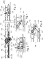
- the Figure 1 shows a conveyor system 100 for conveying piece goods 108 in a conveying direction 102 from a loading side 106 to a removal side 104.
- the piece goods for example a pallet, can be conveyed in the direction 102 via rollers 118 of the conveyor system.
- the movement of the piece goods in the direction 102 over the rollers 118 takes place, for example, as a result of gravity when the conveyor system 100 is inclined slightly downward from the input side 106 to the removal side 104.
- a pallet 108 is now located on the removal side 104 or at the removal position 104, it must be ensured that subsequent pallets do not hit this pallet 108 located at the removal position 104 from behind accumulate, because then, due to the prevailing dynamic pressure, a forklift driver, for example, would no longer be able to remove the pallet 108 from the removal position 104 without damaging the pallet. For this reason, a separating device 110 is provided which, via a stop 116, ensures that when the pallet 108 is located at the removal position 104, no further pallets in the direction 102 can pass that stop 116 and run onto the pallet located at the removal position can.
- a control element 112 for the separating device is also provided so that the stop 116 blocks the further travel of subsequent pallets in the direction 102 at the correct time, this control element 112 being mechanically coupled to the stop 116 via a coupling element 114.
- control element comprises a special conveyor roller 120, for example a brake conveyor roller of the conveyor system 100.
- a conveyor belt located in the conveying plane, which is mounted on a corresponding guide roller. This guide role does not have to be any of the guide rollers 118.
- the control element also has an energy store, which is able to move the coupling element 114 and / or the brake conveyor roller 120 again after removing the pallet 108 from the removal position 104, that the stop can now be moved from the separating position into a conveying position again by the pallet that now follows. In the conveying position, the pallet that now follows is no longer prevented from continuing to travel in the direction 102 in the direction of the removal position 104.
- the Figure 2 shows a schematic cross-sectional view of the separating device 110, comprising the control element 112 and the stop 116 coupled to it.
- the cross-section initially shows the conveyor rollers 118, which are arranged one behind the other in the direction 102 on the conveyor system. That said brake conveyor roller 120 can also be seen, which can be rotated counterclockwise when a pallet is moved over it.
- the brake conveyor roller 120 also called the brake conveyor roller, has a tooth contour via which it is mechanically coupled to a double gear wheel 200.
- a toothed rack 212 is mounted on the double gearwheel via a holding plate 202. This leads to the fact that in the case of the rotation of the brake idler roller in the counterclockwise direction, the rack counter to the direction 102, that is to say in the Figure 2 from left to right. That already out Figure 1
- the known coupling element in the present example is a pull rod 114 which is mechanically coupled to the toothed rack 212.
- the pull rod 114 has itself an elongated hole 224 and is mounted on the conveyor system so as to be displaceable in the direction and opposite to the direction 102 via the elongated hole.
- the separating device 110 has a tension spring 206 which is held on a spring holder 208.
- the tension spring 206 can be pretensioned in the desired manner by means of a spring tensioner 210.
- the brake support roller 120, the double gear 200 and the holding plate for the rack are mounted on the conveyor system via a corresponding holding plate 204.
- the tension spring is tensioned between the spring holder 208 and the toothed rack 212 and ensures that the toothed rack 212 is pulled in the direction 102 from right to left when the brake support roller 120 is in the unloaded state by a pallet.
- the tension spring 206 ensures that the pull rod 212 is retracted from right to left, whereby, depending on the mechanical design, in addition to the double gear 200, the brake support roller 120 also returns to it original position can be rotated back.
- the double gearwheel does not rotate during the backward movement and the teeth of the rack only ratchet over the teeth of the gearwheel.
- the Figure 3 is an enlarged detail of the stop 116 of FIG Figure 2 , where exactly the one in Figure 2 shown state of the stop is reproduced.
- the stop 116 comprises a stop claw 220, which is mounted rotatably about an axis 306. Furthermore, the stop 116 comprises a bolt 226 which is mounted about a further axis 300.
- the stop claw 220 protrudes into the path of any subsequent pallets. If such a pallet hits the stopping claw 220 with its runner, the latter tries to rotate about its axis 306. In the in Figure 3 However, such a rotation is blocked by the bolt 226 in the state shown. This prevents the stop claw 220 from moving from the separating position into its conveying position, as it is, for example, in the Figure 5 shown can be rotated. In the funding position of Fig. 5 the stop claw 220 is located exactly at or preferably below the conveying level and thus does not form an obstacle for the subsequent pallet running on the conveying level.
- FIG Figure 5 the state in which the stop claw 220 is freely rotatable about its axis 306 between the separating position and the conveying position.
- the rack 212 or the pull rod 114 is retracted into a position in which a beveled end 222 of the pull rod 114 allows the bolt 226 to rotate freely about the axis 300 in the counterclockwise direction.
- the rotation is, for example, the result of a gravitational pivoting process of the bolt 226 and / or a rotation process of the bolt 226 supported by an elastic element.
- the elastic element for example a spring, can be stretched between the bolt 226 and the conveyor system.
- the stop claw 220 is constructed in such a way that it remains in the separating position in the unloaded state, also due to gravity and / or with the aid of a spring, in which the stop claw 220 protrudes into the path of the pallets. If a pallet comes from the right from direction 102 and hits it in the in Figure 5 shown State of the bolt on the stop claw 220, the stop claw 220 is rotated about its axis 306 in the counterclockwise direction. By means of the freely rotatable roller 304, the end of the stop claw facing away from the pallet then runs upwards along a surface contour 308 of the bolt 226.
- a brake idler roller 120 was used.
- a brake support roller has an internal planetary gear, for example, which brakes the rotation of the brake support roller 120. This can have the advantage in particular when the pull rod 114 has pushed itself completely under the bolt 226, that is, the tension spring 206 is tensioned. If a pallet located on the brake carrier roller 120 is then lifted off the brake carrier roller, this takes care of it Planetary gear of the brake support roller 120 ensures that the spring 206 can only slowly pull the pull rod 114 back again.
- the retraction of the pull rod 114 ensures a counter-rotation of the double gear 200 and thus also of the brake idler roller 120, with precisely said rotations and movements being slowed down due to the presence of the planetary gear.
- a "normal" rotatable roller could also be used here, with a corresponding delay process in the retraction of the pull rod 114 being controlled by a working cylinder with a throttle check valve arranged between the pull rod 114 and the conveyor system.
Landscapes
- Engineering & Computer Science (AREA)
- Mechanical Engineering (AREA)
- Rollers For Roller Conveyors For Transfer (AREA)
Claims (9)
- Dispositif de séparation (110) pour système de transport (100) permettant le transport de marchandises unitaires (108) dans une direction de transport (102) sur un plan de transport, dans lequel- le dispositif de séparation (110) comprend une butée (116) pour la marchandise unitaire (108) et un élément de commande (112),- l'élément de commande (112) peut être mis en rotation autour d'un axe orienté parallèlement par rapport au plan de transport et perpendiculairement par rapport à la direction de transport (102) en raison d'un contact se produisant dans le plan de transport avec la marchandise unitaire (108),- une mobilité de la butée (116) entre une position de séparation et une position de transport, ainsi qu'un blocage de la butée (116) dans la position de séparation, peuvent être commandées par l'élément de commande (112) en raison de la rotation,- la butée (116) est rendue mobile par l'élément de commande (112) en raison de la rotation,- l'élément de commande (112) est couplé mécaniquement avec la butée (116) par le biais d'une tige de traction (114), où la tige de traction (114) peut se déplacer dans la direction de transport (102) et inversement en raison de la rotation,
dans lequel la butée (116) comprend un crampon d'arrêt (220) et un verrou (226), où- le crampon d'arrêt (220) peut être mis en rotation autour d'un axe (306) orienté parallèlement par rapport au plan de transport et perpendiculairement par rapport à la direction de transport (102) et pénètre à l'intérieur du chemin de parcours de la marchandise unitaire (108), au-delà du plan de transport, dans la position de séparation,- le verrou (226) peut être mis en rotation autour d'un axe (300) orienté parallèlement par rapport au plan de transport et perpendiculairement par rapport à la direction de transport (102) et bloque, dans la position de séparation, une rotation du crampon d'arrêt (220) dans la position de transport,
caractérisé en ce que- l'élément de commande (112) est disposé exclusivement de manière perpendiculaire à l'intérieur et en-dessous du plan de transport, vu à partir de la direction de la marchandise unitaire (108),- la tige de traction (114) est conçue pour, lors de la transition de sa position de libération vers sa position de blocage, contourner le verrou (226) et de se tourner ainsi dans la position de séparation,- la tige de traction (114) présente une déclivité (222) à son extrémité orientée vers le verrou (226), où la déclivité (222) est conçue pour que, lors du contournement du verrou (226), le verrou (226) est mis en rotation autour de son axe vers le haut en direction de la marchandise unitaire (108), pour, dans cette position, bloquer un pivotement en retour du crampon d'arrêt (220) se trouvant dans la position de séparation,- la tige de traction (114) est conçue de sorte que, lorsque la tige de traction (114) se trouve par contre dans la position de libération, le verrou (226) peut de nouveau se mettre en rotation autour de son axe, ce par quoi le blocage du crampon d'arrêt est levé. - Dispositif de séparation (110) selon la revendication 1, dans lequel l'élément de commande (112)- comprend un rouleau de transport (120) du système de transport (100), où le rouleau de transport (120) peut être mis en rotation autour de l'axe du rouleau de transport (120) orienté parallèlement par rapport au plan de transport et perpendiculairement par rapport à la direction de transport (102) en raison du contact se produisant dans le plan de transport avec la marchandise unitaire (108), et/ou- comprend une bande transporteuse, où la bande transporteuse est logée sur un rouleau de guidage, où la bande transporteuse peut être mise en rotation autour de l'axe du rouleau de guidage orienté parallèlement par rapport au plan de transport et perpendiculairement par rapport à la direction de transport (102) en raison du contact de la bande transporteuse se produisant dans le plan de transport avec la marchandise unitaire (108).
- Dispositif de séparation (110) selon la revendication 1, doté en outre d'un accumulateur d'énergie (206), où l'accumulateur d'énergie (206) est disposé pour- gagner de l'énergie lorsque l'élément de commande (112) est en rotation autour de l'axe en raison du contact avec la marchandise unitaire (108), et- délivrer de l'énergie par le déplacement de la tige de traction (114) à l'état sans contact de l'élément de commande (112) avec la marchandise unitaire (108) à partir d'une position de blocage vers une position de libération, où la mobilité de la butée (116) entre la position de séparation et la position de transport dans la position de libération est donnée et le blocage de la butée (116) est donné dans la position de blocage.
- Dispositif de séparation (110) selon la revendication 1, dans lequel- le verrou (226) est conçu pour adopter la position de transport du fait de la contrainte par la force de la gravité et/ou par la force d'un élément élastique dans la position de libération de la tige de traction (114), et/ou- le crampon d'arrêt (220) est conçu pour adopter la position de séparation du fait de la contrainte par la force de la gravité et/ou par la force d'un élément élastique dans la position de libération de la tige de traction (114).
- Dispositif de séparation (110) selon la revendication 1 ou la revendication 4, dans lequel le crampon d'arrêt (220) présente un rouleau (302) tournant librement, où le crampon d'arrêt (220) est adjacent au niveau du verrou (226) exclusivement par le biais du rouleau (302).
- Dispositif de séparation (110) selon la revendication 5, dans lequel le rouleau (302) est logé dans une coulisse (304) du crampon d'arrêt (220), où le verrou (226) présente une structure de surface (308), le long de laquelle le rouleau (302) peut se dérouler vers la position de transport lors de la transition de la position de séparation vers la position de transport, où le contour de la surface (308) et la coulisse (304) sont moulés pour minimiser les forces de friction en rotation exercées par le rouleau (302) sur le contour de la surface (308) lors de la transition du verrou (226) de la position de séparation vers la position de transport.
- Dispositif de séparation (110) selon l'une des revendications précédentes, doté en outre d'une unité de retard, où l'unité de retard est conçue pour retarder dans le temps la levée du blocage de la butée (116) afin de permettre le déplacement ultérieur de la butée (116) de la position de séparation vers la position de transport.
- Dispositif de séparation (110) selon la revendication 7, dans lequel l'unité de retard comprend un rouleau de freinage (120) du système de transport (100).
- Système de transport (100) pour le transport de marchandise unitaire (108) dans une direction de transport (102) sur un plan de transport, où le système de transport (100) comprend un dispositif de séparation(110) selon l'une des revendications précédentes.
Priority Applications (1)
| Application Number | Priority Date | Filing Date | Title |
|---|---|---|---|
| PL17197648T PL3312111T3 (pl) | 2016-10-21 | 2017-10-20 | Przyrząd separujący układu przenoszącego do przenoszenia drobnicy |
Applications Claiming Priority (1)
| Application Number | Priority Date | Filing Date | Title |
|---|---|---|---|
| DE102016220676.1A DE102016220676B4 (de) | 2016-10-21 | 2016-10-21 | Separiervorrichtung für ein Fördersystem zur Beförderung von Stückgut |
Publications (2)
| Publication Number | Publication Date |
|---|---|
| EP3312111A1 EP3312111A1 (fr) | 2018-04-25 |
| EP3312111B1 true EP3312111B1 (fr) | 2021-06-23 |
Family
ID=60153221
Family Applications (1)
| Application Number | Title | Priority Date | Filing Date |
|---|---|---|---|
| EP17197648.3A Active EP3312111B1 (fr) | 2016-10-21 | 2017-10-20 | Dispositif de séparation pour un système de transport destiné à transporter la marchandise |
Country Status (3)
| Country | Link |
|---|---|
| EP (1) | EP3312111B1 (fr) |
| DE (1) | DE102016220676B4 (fr) |
| PL (1) | PL3312111T3 (fr) |
Families Citing this family (6)
| Publication number | Priority date | Publication date | Assignee | Title |
|---|---|---|---|---|
| CN108529207B (zh) * | 2018-05-09 | 2024-03-19 | 广东嘉腾机器人自动化有限公司 | 阻挡装置及自动化输送系统 |
| CN109702483B (zh) * | 2019-02-22 | 2024-03-22 | 东莞顺合丰电业有限公司 | 装配扬声器的生产设备 |
| CN110294313A (zh) * | 2019-07-13 | 2019-10-01 | 芜湖市恒浩机械制造有限公司 | 一种活塞环分料输送用的分离机构 |
| CN113333293A (zh) * | 2021-05-11 | 2021-09-03 | 科捷智能科技股份有限公司 | 输送线料箱分离装置 |
| CN113562451A (zh) * | 2021-08-12 | 2021-10-29 | 昆山同日工业自动化有限公司 | 料箱分离器 |
| CN116692101B (zh) * | 2023-08-03 | 2023-10-03 | 常州鑫德源恒耐火板装饰材料股份有限公司 | 一种耐火板产线用回流运转包覆系统 |
Citations (2)
| Publication number | Priority date | Publication date | Assignee | Title |
|---|---|---|---|---|
| DE3243086C1 (de) * | 1982-11-22 | 1984-06-07 | Interroll-Fördertechnik GmbH & Co KG, 5632 Wermelskirchen | Vorrichtung zum Trennen von Paletten auf einer Rollenbahn |
| EP1897823A2 (fr) * | 2006-09-06 | 2008-03-12 | BITO-LAGERTECHNIK BITTMANN GmbH | Couloir de roulement doté d'un dispositif de séparation |
Family Cites Families (8)
| Publication number | Priority date | Publication date | Assignee | Title |
|---|---|---|---|---|
| JPS566346Y2 (fr) | 1976-10-06 | 1981-02-12 | ||
| JP2618948B2 (ja) * | 1988-01-25 | 1997-06-11 | 鹿島建設株式会社 | パレット搬送貯蔵装置 |
| US5213189A (en) * | 1992-05-26 | 1993-05-25 | Interroll Holding A.G. | Load separating mechanism for a roller conveyor |
| DE9404684U1 (de) * | 1994-03-19 | 1994-05-19 | Nedcon Magazijninrichting B.V., Doetinchem | Vorrichtung zum Zurückhalten von entlang einer Rollenbahn, insbesondere der Rollenbahn eines Durchlaufregals, verfahrbaren Gegenständen, z.B. Paletten |
| DE202011004045U1 (de) * | 2011-03-16 | 2011-09-13 | Aqs Logistic Systems Gmbh | Rollenbahn zum Transport von Stückgütern, z.B. Paletten oder Kisten |
| DE202011004513U1 (de) * | 2011-03-30 | 2012-07-10 | Interroll-Holding Ag | Rollenfördermodul mit Separationsvorrichtung |
| EP2517983B1 (fr) * | 2011-04-26 | 2013-10-23 | Interroll Holding AG | Convoyeur à rouleaux doté d'un séparateur de charges |
| PL2517982T3 (pl) | 2011-04-26 | 2014-06-30 | Interroll Holding Ag | Urządzenie separatora z opóźnieniem czasowym |
-
2016
- 2016-10-21 DE DE102016220676.1A patent/DE102016220676B4/de active Active
-
2017
- 2017-10-20 EP EP17197648.3A patent/EP3312111B1/fr active Active
- 2017-10-20 PL PL17197648T patent/PL3312111T3/pl unknown
Patent Citations (2)
| Publication number | Priority date | Publication date | Assignee | Title |
|---|---|---|---|---|
| DE3243086C1 (de) * | 1982-11-22 | 1984-06-07 | Interroll-Fördertechnik GmbH & Co KG, 5632 Wermelskirchen | Vorrichtung zum Trennen von Paletten auf einer Rollenbahn |
| EP1897823A2 (fr) * | 2006-09-06 | 2008-03-12 | BITO-LAGERTECHNIK BITTMANN GmbH | Couloir de roulement doté d'un dispositif de séparation |
Also Published As
| Publication number | Publication date |
|---|---|
| EP3312111A1 (fr) | 2018-04-25 |
| DE102016220676B4 (de) | 2022-10-13 |
| PL3312111T3 (pl) | 2021-12-13 |
| DE102016220676A1 (de) | 2018-04-26 |
Similar Documents
| Publication | Publication Date | Title |
|---|---|---|
| EP3312111B1 (fr) | Dispositif de séparation pour un système de transport destiné à transporter la marchandise | |
| WO2010135756A1 (fr) | Dispositif de préparation de commandes | |
| EP1189825A1 (fr) | Dispositif de transport et/ou de stockage pour marchandises en colis | |
| DE102012109162B4 (de) | Verfahren zur Entnahme einzelner Behälter aus einem Durchlaufregal | |
| EP2500294B1 (fr) | Transporteur à rouleaux pour le transport de marchandises , p. ex. palettes ou caisses | |
| EP3878775B1 (fr) | Bande à rouleaux pourvu de dispositif de freinage | |
| DE1481291C3 (de) | Speicherrollenbahn | |
| DE102009008155A1 (de) | Entladestation zum automatisierten Trennen eines Gebindes von einem Ladehilfsmittel | |
| EP3746378A1 (fr) | Système convoyeur accumulateur | |
| EP3681824B1 (fr) | Système de stockage automatisé doté de moyens de transfert guidés | |
| EP2543613B1 (fr) | Étagère traversante dotée d'un dispositif de séparation mécanique lâche | |
| DE102011078600B3 (de) | Durchlaufregal mit Steuerfahne | |
| DE3245879C2 (de) | Etikettierstation für Gegenstände, wie Flaschen | |
| EP2181055A1 (fr) | Colonne d'empilage horizontale | |
| DE1915028C (de) | Rollenförderbahn mit einer Sperr- und Vereinzelungsvorrichtung an der Abgabestelle | |
| DE102024114464A1 (de) | Rollenbahn zur führung von mehreren hintereinander angeordneten lagereinheiten | |
| DE102020105818A1 (de) | Rollkörperbahn | |
| DE29711052U1 (de) | Rollen-Fördervorrichtung zum Transportieren von Fördergütern entlang einer Förderstrecke | |
| DE102009044783A1 (de) | Transportbahn für Stückgüter | |
| DE202007009798U1 (de) | Rollenbahn, umfassend einen Rahmen zur Aufnahme mehrerer hintereinander angeordneter Rollen | |
| DE2043915A1 (de) | Automatische Beladevorrichtung fur Stuckguter | |
| DE202017100367U1 (de) | Rollenbahn mit Radstopp | |
| DD145256B1 (de) | Klinkenrollbahn zum bereitstellen von zylindrischem foerdergut | |
| DE102011078602A1 (de) | Durchlaufregal mit Schnappriegelverschluss | |
| DE8204226U1 (de) | Etikettierstation fuer gegenstaende, wie flaschen |
Legal Events
| Date | Code | Title | Description |
|---|---|---|---|
| PUAI | Public reference made under article 153(3) epc to a published international application that has entered the european phase |
Free format text: ORIGINAL CODE: 0009012 |
|
| STAA | Information on the status of an ep patent application or granted ep patent |
Free format text: STATUS: THE APPLICATION HAS BEEN PUBLISHED |
|
| AK | Designated contracting states |
Kind code of ref document: A1 Designated state(s): AL AT BE BG CH CY CZ DE DK EE ES FI FR GB GR HR HU IE IS IT LI LT LU LV MC MK MT NL NO PL PT RO RS SE SI SK SM TR |
|
| AX | Request for extension of the european patent |
Extension state: BA ME |
|
| STAA | Information on the status of an ep patent application or granted ep patent |
Free format text: STATUS: REQUEST FOR EXAMINATION WAS MADE |
|
| 17P | Request for examination filed |
Effective date: 20180416 |
|
| RBV | Designated contracting states (corrected) |
Designated state(s): AL AT BE BG CH CY CZ DE DK EE ES FI FR GB GR HR HU IE IS IT LI LT LU LV MC MK MT NL NO PL PT RO RS SE SI SK SM TR |
|
| STAA | Information on the status of an ep patent application or granted ep patent |
Free format text: STATUS: EXAMINATION IS IN PROGRESS |
|
| 17Q | First examination report despatched |
Effective date: 20180727 |
|
| GRAP | Despatch of communication of intention to grant a patent |
Free format text: ORIGINAL CODE: EPIDOSNIGR1 |
|
| STAA | Information on the status of an ep patent application or granted ep patent |
Free format text: STATUS: GRANT OF PATENT IS INTENDED |
|
| RIC1 | Information provided on ipc code assigned before grant |
Ipc: B65G 1/08 20060101ALN20200826BHEP Ipc: B65G 47/88 20060101AFI20200826BHEP |
|
| INTG | Intention to grant announced |
Effective date: 20200914 |
|
| GRAJ | Information related to disapproval of communication of intention to grant by the applicant or resumption of examination proceedings by the epo deleted |
Free format text: ORIGINAL CODE: EPIDOSDIGR1 |
|
| STAA | Information on the status of an ep patent application or granted ep patent |
Free format text: STATUS: EXAMINATION IS IN PROGRESS |
|
| GRAP | Despatch of communication of intention to grant a patent |
Free format text: ORIGINAL CODE: EPIDOSNIGR1 |
|
| STAA | Information on the status of an ep patent application or granted ep patent |
Free format text: STATUS: GRANT OF PATENT IS INTENDED |
|
| INTC | Intention to grant announced (deleted) | ||
| RIC1 | Information provided on ipc code assigned before grant |
Ipc: B65G 47/88 20060101AFI20201217BHEP Ipc: B65G 1/08 20060101ALN20201217BHEP |
|
| INTG | Intention to grant announced |
Effective date: 20210118 |
|
| GRAS | Grant fee paid |
Free format text: ORIGINAL CODE: EPIDOSNIGR3 |
|
| GRAA | (expected) grant |
Free format text: ORIGINAL CODE: 0009210 |
|
| STAA | Information on the status of an ep patent application or granted ep patent |
Free format text: STATUS: THE PATENT HAS BEEN GRANTED |
|
| AK | Designated contracting states |
Kind code of ref document: B1 Designated state(s): AL AT BE BG CH CY CZ DE DK EE ES FI FR GB GR HR HU IE IS IT LI LT LU LV MC MK MT NL NO PL PT RO RS SE SI SK SM TR |
|
| REG | Reference to a national code |
Ref country code: GB Ref legal event code: FG4D Free format text: NOT ENGLISH |
|
| REG | Reference to a national code |
Ref country code: CH Ref legal event code: EP |
|
| REG | Reference to a national code |
Ref country code: DE Ref legal event code: R096 Ref document number: 502017010724 Country of ref document: DE Ref country code: AT Ref legal event code: REF Ref document number: 1404146 Country of ref document: AT Kind code of ref document: T Effective date: 20210715 |
|
| REG | Reference to a national code |
Ref country code: IE Ref legal event code: FG4D Free format text: LANGUAGE OF EP DOCUMENT: GERMAN |
|
| REG | Reference to a national code |
Ref country code: LT Ref legal event code: MG9D |
|
| PG25 | Lapsed in a contracting state [announced via postgrant information from national office to epo] |
Ref country code: FI Free format text: LAPSE BECAUSE OF FAILURE TO SUBMIT A TRANSLATION OF THE DESCRIPTION OR TO PAY THE FEE WITHIN THE PRESCRIBED TIME-LIMIT Effective date: 20210623 Ref country code: LT Free format text: LAPSE BECAUSE OF FAILURE TO SUBMIT A TRANSLATION OF THE DESCRIPTION OR TO PAY THE FEE WITHIN THE PRESCRIBED TIME-LIMIT Effective date: 20210623 Ref country code: BG Free format text: LAPSE BECAUSE OF FAILURE TO SUBMIT A TRANSLATION OF THE DESCRIPTION OR TO PAY THE FEE WITHIN THE PRESCRIBED TIME-LIMIT Effective date: 20210923 Ref country code: HR Free format text: LAPSE BECAUSE OF FAILURE TO SUBMIT A TRANSLATION OF THE DESCRIPTION OR TO PAY THE FEE WITHIN THE PRESCRIBED TIME-LIMIT Effective date: 20210623 |
|
| PG25 | Lapsed in a contracting state [announced via postgrant information from national office to epo] |
Ref country code: GR Free format text: LAPSE BECAUSE OF FAILURE TO SUBMIT A TRANSLATION OF THE DESCRIPTION OR TO PAY THE FEE WITHIN THE PRESCRIBED TIME-LIMIT Effective date: 20210924 Ref country code: LV Free format text: LAPSE BECAUSE OF FAILURE TO SUBMIT A TRANSLATION OF THE DESCRIPTION OR TO PAY THE FEE WITHIN THE PRESCRIBED TIME-LIMIT Effective date: 20210623 Ref country code: NO Free format text: LAPSE BECAUSE OF FAILURE TO SUBMIT A TRANSLATION OF THE DESCRIPTION OR TO PAY THE FEE WITHIN THE PRESCRIBED TIME-LIMIT Effective date: 20210923 Ref country code: SE Free format text: LAPSE BECAUSE OF FAILURE TO SUBMIT A TRANSLATION OF THE DESCRIPTION OR TO PAY THE FEE WITHIN THE PRESCRIBED TIME-LIMIT Effective date: 20210623 Ref country code: RS Free format text: LAPSE BECAUSE OF FAILURE TO SUBMIT A TRANSLATION OF THE DESCRIPTION OR TO PAY THE FEE WITHIN THE PRESCRIBED TIME-LIMIT Effective date: 20210623 |
|
| REG | Reference to a national code |
Ref country code: NL Ref legal event code: MP Effective date: 20210623 |
|
| PG25 | Lapsed in a contracting state [announced via postgrant information from national office to epo] |
Ref country code: EE Free format text: LAPSE BECAUSE OF FAILURE TO SUBMIT A TRANSLATION OF THE DESCRIPTION OR TO PAY THE FEE WITHIN THE PRESCRIBED TIME-LIMIT Effective date: 20210623 Ref country code: CZ Free format text: LAPSE BECAUSE OF FAILURE TO SUBMIT A TRANSLATION OF THE DESCRIPTION OR TO PAY THE FEE WITHIN THE PRESCRIBED TIME-LIMIT Effective date: 20210623 Ref country code: NL Free format text: LAPSE BECAUSE OF FAILURE TO SUBMIT A TRANSLATION OF THE DESCRIPTION OR TO PAY THE FEE WITHIN THE PRESCRIBED TIME-LIMIT Effective date: 20210623 Ref country code: RO Free format text: LAPSE BECAUSE OF FAILURE TO SUBMIT A TRANSLATION OF THE DESCRIPTION OR TO PAY THE FEE WITHIN THE PRESCRIBED TIME-LIMIT Effective date: 20210623 Ref country code: PT Free format text: LAPSE BECAUSE OF FAILURE TO SUBMIT A TRANSLATION OF THE DESCRIPTION OR TO PAY THE FEE WITHIN THE PRESCRIBED TIME-LIMIT Effective date: 20211025 Ref country code: ES Free format text: LAPSE BECAUSE OF FAILURE TO SUBMIT A TRANSLATION OF THE DESCRIPTION OR TO PAY THE FEE WITHIN THE PRESCRIBED TIME-LIMIT Effective date: 20210623 Ref country code: SK Free format text: LAPSE BECAUSE OF FAILURE TO SUBMIT A TRANSLATION OF THE DESCRIPTION OR TO PAY THE FEE WITHIN THE PRESCRIBED TIME-LIMIT Effective date: 20210623 Ref country code: SM Free format text: LAPSE BECAUSE OF FAILURE TO SUBMIT A TRANSLATION OF THE DESCRIPTION OR TO PAY THE FEE WITHIN THE PRESCRIBED TIME-LIMIT Effective date: 20210623 |
|
| REG | Reference to a national code |
Ref country code: DE Ref legal event code: R097 Ref document number: 502017010724 Country of ref document: DE |
|
| PG25 | Lapsed in a contracting state [announced via postgrant information from national office to epo] |
Ref country code: DK Free format text: LAPSE BECAUSE OF FAILURE TO SUBMIT A TRANSLATION OF THE DESCRIPTION OR TO PAY THE FEE WITHIN THE PRESCRIBED TIME-LIMIT Effective date: 20210623 |
|
| PLBE | No opposition filed within time limit |
Free format text: ORIGINAL CODE: 0009261 |
|
| STAA | Information on the status of an ep patent application or granted ep patent |
Free format text: STATUS: NO OPPOSITION FILED WITHIN TIME LIMIT |
|
| 26N | No opposition filed |
Effective date: 20220324 |
|
| PG25 | Lapsed in a contracting state [announced via postgrant information from national office to epo] |
Ref country code: AL Free format text: LAPSE BECAUSE OF FAILURE TO SUBMIT A TRANSLATION OF THE DESCRIPTION OR TO PAY THE FEE WITHIN THE PRESCRIBED TIME-LIMIT Effective date: 20210623 |
|
| REG | Reference to a national code |
Ref country code: BE Ref legal event code: MM Effective date: 20211031 |
|
| GBPC | Gb: european patent ceased through non-payment of renewal fee |
Effective date: 20211020 |
|
| PG25 | Lapsed in a contracting state [announced via postgrant information from national office to epo] |
Ref country code: MC Free format text: LAPSE BECAUSE OF FAILURE TO SUBMIT A TRANSLATION OF THE DESCRIPTION OR TO PAY THE FEE WITHIN THE PRESCRIBED TIME-LIMIT Effective date: 20210623 |
|
| PG25 | Lapsed in a contracting state [announced via postgrant information from national office to epo] |
Ref country code: LU Free format text: LAPSE BECAUSE OF NON-PAYMENT OF DUE FEES Effective date: 20211020 Ref country code: IT Free format text: LAPSE BECAUSE OF FAILURE TO SUBMIT A TRANSLATION OF THE DESCRIPTION OR TO PAY THE FEE WITHIN THE PRESCRIBED TIME-LIMIT Effective date: 20210623 Ref country code: GB Free format text: LAPSE BECAUSE OF NON-PAYMENT OF DUE FEES Effective date: 20211020 Ref country code: BE Free format text: LAPSE BECAUSE OF NON-PAYMENT OF DUE FEES Effective date: 20211031 |
|
| PG25 | Lapsed in a contracting state [announced via postgrant information from national office to epo] |
Ref country code: IE Free format text: LAPSE BECAUSE OF NON-PAYMENT OF DUE FEES Effective date: 20211020 |
|
| PG25 | Lapsed in a contracting state [announced via postgrant information from national office to epo] |
Ref country code: HU Free format text: LAPSE BECAUSE OF FAILURE TO SUBMIT A TRANSLATION OF THE DESCRIPTION OR TO PAY THE FEE WITHIN THE PRESCRIBED TIME-LIMIT; INVALID AB INITIO Effective date: 20171020 |
|
| PG25 | Lapsed in a contracting state [announced via postgrant information from national office to epo] |
Ref country code: CY Free format text: LAPSE BECAUSE OF FAILURE TO SUBMIT A TRANSLATION OF THE DESCRIPTION OR TO PAY THE FEE WITHIN THE PRESCRIBED TIME-LIMIT Effective date: 20210623 |
|
| PG25 | Lapsed in a contracting state [announced via postgrant information from national office to epo] |
Ref country code: MK Free format text: LAPSE BECAUSE OF FAILURE TO SUBMIT A TRANSLATION OF THE DESCRIPTION OR TO PAY THE FEE WITHIN THE PRESCRIBED TIME-LIMIT Effective date: 20210623 |
|
| PG25 | Lapsed in a contracting state [announced via postgrant information from national office to epo] |
Ref country code: MT Free format text: LAPSE BECAUSE OF FAILURE TO SUBMIT A TRANSLATION OF THE DESCRIPTION OR TO PAY THE FEE WITHIN THE PRESCRIBED TIME-LIMIT Effective date: 20210623 |
|
| REG | Reference to a national code |
Ref country code: CH Ref legal event code: U11 Free format text: ST27 STATUS EVENT CODE: U-0-0-U10-U11 (AS PROVIDED BY THE NATIONAL OFFICE) Effective date: 20251101 |
|
| PG25 | Lapsed in a contracting state [announced via postgrant information from national office to epo] |
Ref country code: TR Free format text: LAPSE BECAUSE OF FAILURE TO SUBMIT A TRANSLATION OF THE DESCRIPTION OR TO PAY THE FEE WITHIN THE PRESCRIBED TIME-LIMIT Effective date: 20210623 |
|
| PGFP | Annual fee paid to national office [announced via postgrant information from national office to epo] |
Ref country code: DE Payment date: 20251021 Year of fee payment: 9 |
|
| PGFP | Annual fee paid to national office [announced via postgrant information from national office to epo] |
Ref country code: AT Payment date: 20251022 Year of fee payment: 9 |
|
| PGFP | Annual fee paid to national office [announced via postgrant information from national office to epo] |
Ref country code: FR Payment date: 20251030 Year of fee payment: 9 |
|
| PGFP | Annual fee paid to national office [announced via postgrant information from national office to epo] |
Ref country code: CH Payment date: 20251101 Year of fee payment: 9 |
|
| PGFP | Annual fee paid to national office [announced via postgrant information from national office to epo] |
Ref country code: PL Payment date: 20251010 Year of fee payment: 9 |