EP1897823A2 - Couloir de roulement doté d'un dispositif de séparation - Google Patents
Couloir de roulement doté d'un dispositif de séparation Download PDFInfo
- Publication number
- EP1897823A2 EP1897823A2 EP07016768A EP07016768A EP1897823A2 EP 1897823 A2 EP1897823 A2 EP 1897823A2 EP 07016768 A EP07016768 A EP 07016768A EP 07016768 A EP07016768 A EP 07016768A EP 1897823 A2 EP1897823 A2 EP 1897823A2
- Authority
- EP
- European Patent Office
- Prior art keywords
- stop
- guide
- conveying direction
- control lug
- control
- Prior art date
- Legal status (The legal status is an assumption and is not a legal conclusion. Google has not performed a legal analysis and makes no representation as to the accuracy of the status listed.)
- Withdrawn
Links
- 239000002800 charge carrier Substances 0.000 claims description 32
- 238000011144 upstream manufacturing Methods 0.000 claims 1
- 238000000605 extraction Methods 0.000 abstract 1
- 238000000926 separation method Methods 0.000 description 4
- 239000000969 carrier Substances 0.000 description 3
- 230000000694 effects Effects 0.000 description 1
- 230000005484 gravity Effects 0.000 description 1
- 238000000034 method Methods 0.000 description 1
- 230000000717 retained effect Effects 0.000 description 1
Images


Classifications
-
- B—PERFORMING OPERATIONS; TRANSPORTING
- B65—CONVEYING; PACKING; STORING; HANDLING THIN OR FILAMENTARY MATERIAL
- B65G—TRANSPORT OR STORAGE DEVICES, e.g. CONVEYORS FOR LOADING OR TIPPING, SHOP CONVEYOR SYSTEMS OR PNEUMATIC TUBE CONVEYORS
- B65G1/00—Storing articles, individually or in orderly arrangement, in warehouses or magazines
- B65G1/02—Storage devices
- B65G1/04—Storage devices mechanical
- B65G1/06—Storage devices mechanical with means for presenting articles for removal at predetermined position or level
- B65G1/08—Storage devices mechanical with means for presenting articles for removal at predetermined position or level the articles being fed by gravity
-
- B—PERFORMING OPERATIONS; TRANSPORTING
- B65—CONVEYING; PACKING; STORING; HANDLING THIN OR FILAMENTARY MATERIAL
- B65G—TRANSPORT OR STORAGE DEVICES, e.g. CONVEYORS FOR LOADING OR TIPPING, SHOP CONVEYOR SYSTEMS OR PNEUMATIC TUBE CONVEYORS
- B65G47/00—Article or material-handling devices associated with conveyors; Methods employing such devices
- B65G47/74—Feeding, transfer, or discharging devices of particular kinds or types
- B65G47/88—Separating or stopping elements, e.g. fingers
- B65G47/8807—Separating or stopping elements, e.g. fingers with one stop
- B65G47/8823—Pivoting stop, swinging in or out of the path of the article
-
- B—PERFORMING OPERATIONS; TRANSPORTING
- B65—CONVEYING; PACKING; STORING; HANDLING THIN OR FILAMENTARY MATERIAL
- B65G—TRANSPORT OR STORAGE DEVICES, e.g. CONVEYORS FOR LOADING OR TIPPING, SHOP CONVEYOR SYSTEMS OR PNEUMATIC TUBE CONVEYORS
- B65G2205/00—Stopping elements used in conveyors to stop articles or arrays of articles
- B65G2205/04—Stopping elements used in conveyors to stop articles or arrays of articles where the stop device is not adaptable
Definitions
- the invention relates to a flow rack with separating device for separating charge carriers of different lengths conveyed from a feed side to a discharge side according to the preamble of patent claim 1.
- a separating device which separates a first frontmost pallet from a subsequent second pallet.
- the first pallet moves in the conveying direction to the removal side of the flow rack, it pivots an adjacent to the withdrawal side provided control flag from a first position in which it extends beyond the conveying plane addition, in a second position in which it lies in the conveying plane.
- the control lug is connected via an actuating linkage with a downstream arranged in the conveying direction stop means that the stop means is moved in said movement from a release position in which it is below the conveying plane in a stop position in which they are beyond the conveying plane extends. At this stop means suggests the subsequent second pallet.
- the pilot flag device is moved back to the first position by a biasing device.
- the stop device via the actuating linkage from the stop position in the Release position moves so that the second pallet can move to the removal side. This movement of the pallets allows the first pallet to be removed from the flow shelf without back pressure.
- control lug In known separating devices, the control lug is arranged adjacent to the removal side, so that its control takes place through the front edge of the charge carrier. They are each tuned only to a specific charge carrier length. The distance between the control lug and the stop device is adjusted so that the distance between the stop device and the rear end of the first charge carrier is as small as possible in order to avoid a loss of space.
- charge carriers of different lengths are used in the same pass path of a flow rack.
- An example of use are e.g. Euro pallets with a length of 1200 mm which are stored mixed with pallets with a length of 600 mm in the flow rack. The shorter pallets are always stored in pairs.
- the known separating device is tuned to europallets with a length of 1200 mm, after conveying a short pallet with 600 mm to the unloading side, there is a clearance with the length of the short pallet between the stop device and the rear end of the first short pallet.
- the invention has for its object to provide a flow shelf with structurally simple means, on the removal side carriers different length can be separated with little loss of space.
- the flow shelf according to the invention allows the separation of a long charge carrier or two or more short charge carriers from the other charge carriers, which are in the passage path of the flow shelf.
- the stop device is not as in the prior art by the leading edge of the Charge carrier, but controlled by its trailing edge.
- the distance between the control lug device and the removal stop is designed according to the shortest charge carrier to be transported.
- the flow rack according to the invention can be designed for example for the separation of Euro pallets with a length of 1200 mm. At the same time, however, the separation of two subsequent pallets with a length of 600 mm is possible.
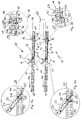
- the structure of the flow shelf 10 will be explained below with reference to FIGS. 1, 1a and 1b.
- the flow rack 10 has one or more passages 12 arranged side by side, whose conveying plane FE is formed by transport rollers 14, wherein the conveying plane FE is inclined downwards from the feed side AS to the discharge side ES.
- a separating device is provided, which has a separating stop device 16 and a control lug device 20, which are arranged one after the other in the conveying direction FR.
- the control lug device 20 and the separation stop device 16 are connected to one another by an actuating linkage 18.
- the control lug device 20 comprises a control lug 22 with transport rollers 24, which extend from the position shown in FIG. 1 a, in the direction of the removal side ES beyond the conveying plane FE extends forward, in a second position about a pivot axis 26 is pivotable in which form the transport rollers 24 together with the transport rollers 14, the conveying plane FE.
- This position is shown for example in Fig. 4a.
- the actuating rod 30 of the actuating linkage 18 is articulated at a pivot point 28 so that the actuating rod 30 is moved during the pivoting of the control lug 22 from the first position to the second position to the front, ie in the direction of the withdrawal side ES.
- the separating stop device 16 comprises a stop element 42 pivotable about an axis 50 extending transversely to the conveying direction FR, with a stop arm 44 which normally extends beyond the conveying plane FE and a downwardly extending guide arm 46. At the lower end of the guide arm 46 is a provided transversely to the conveying direction FR extending guide pin 48.
- the guide pin 48 extends through a provided in the control plate 34 first guide opening 38 which is formed substantially part-circular, so that the guide pin 48 in the position shown in Fig. 1 b of the control element 34 at a pivoting of the stop member 42 in the guide opening 38 can move back and forth.
- a latching recess 40 is provided, into which the guide pin 48 engages when the control plate 34 is in a lower position, as shown for example in Fig. 5b.
- a second guide opening 36 is provided in the control plate 34, through which a fixed guide rod 52 extends transversely to the conveying direction FR.
- the second guide opening 36 has in its lower front corner a recess 54, into which engages the guide rod 52 in the position shown in Fig. 1 b. From the recess 54, the second guide opening 36 widens in the rear direction upward via a removal-side oblique ramp section 55, the ramp section 55 terminating horizontally via a bend.
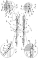
- FIG. 2, 2a and 2b show the flow shelf 10 of FIG. 1 before impact of a long load carrier 60 on the stop element 42.
- the control lug 22 is held by the spring force of a spring means (not shown) in the first position in which they are extending beyond the conveying plane FE.
- the actuating rod 30 is therefore in its rear position, whereby the control plate 34 has been moved so far back that the guide rod 52 is in the recess 54.
- the control plate 34 is therefore in a raised position.
- Fig. 3 shows the pass path 12 after the impact of the charge carrier 60 on the stop arm 44 of the stopper 42.
- the stop member 42 By hitting the front edge of the load carrier 60 on the stop arm 44, the stop member 42 is pivoted so far until the stop arm 44 below the conveyor plane FE is located so that the charge carrier 60 can move further in the conveying direction FR.
- the guide pin 48 is thereby moved within the part-circular portion of the guide opening 38 from the left in Fig. 2b position to a middle position below the locking recess 40, as shown in Fig. 3b.
- the guide rod 52 is still in the recess 54.
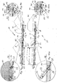
- FIG. 4 shows the flow rack 10 in a transport position of the load carrier 60, in which the front edge of the load carrier 60 has pivoted the control lug 22 into the second position.
- the actuating rod 30 has been moved from the rear position shown in Fig. 3 in the front position shown in FIG. 4, which is why the guide pin 38 in the rear, in Fig. 4b right end of the part-circular portion of the guide opening 38 is located.
- the guide rod 52 is located in the enlarged space of the guide opening 36.
- the control plate 34 is further held in an upper position, since the upper edge of the guide opening 38 rests on the guide pin 48.
- FIG. 5 shows the flow shelf 10 after the trailing edge of the load carrier 60 has passed the stop element 42.
- no force is exerted on the stop arm 44, so that the stop element 42 is pivoted back by gravity or spring force back so far until the stop arm 44 extends over the conveying plane FE.
- the guide pin 48 is thereby pivoted so far to the left within the part-circular portion of the guide opening 38 until it is below the locking recess 40. Since the guide rod 52 is in the free space of the second guide hole 36, the control plate 34 can move down and the guide pin 48 comes in the locking recess 40 for engagement. As a result, the stop element 42 is locked. It can not perform a pivoting movement (in Fig. 5b counterclockwise) when a force is exerted on the stop arm 44 in the conveying direction FR.
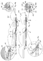
- FIG. 6, 6a and 6b show the passage track 12 at the time at which the charge carrier 60 strikes with its front edge on the removal stop 56 on the removal side ES.
- the length b of the load carrier 60 in the conveying direction is greater than the distance a between the removal stop 56 and the front end of the control lug 22 when the control lug 22 is in its second position.
- the load carrier 60 exerts a weight force on the control lug 22 so that the control lug 22 remains in its second position. Therefore, the stopper member 42 is further in its locked position, so that a subsequent charge carrier 70 comes to a stop with its front edge on the stop arm 44.
- the charge carriers 60 and 70 are at a distance from each other.
- FIGS. 7, 7a and 7b show the passage track 12 at the time of lifting of the load carrier 60, for example by a forklift.
- the control lug 22 abuts with its front end on the underside of the charge carrier 60. It is pivoted by the spring force up above the conveying plane FE out, but is still between the first and the second position, d. H. she is not yet completely turned up.
- the control plate 34 has been moved so far forward by this movement, that the guide rod 52 is located approximately in the central region of the guide opening 36 at the bend to the ramp portion 55.
- the guide rod 52 deforms elastically and the stop member 42 is locked until the release of the control lug 22.
- This elasticity prevents the guide pin 48 is pulled out of the locking recess 40, so the stop element 42 is still locked. For this reason, the subsequent load carrier 70 is still retained by the stopper arm 44.
- Fig. 8 shows the flow shelf 10 at the time in which the carrier 60 is completely lifted off the pass path 12 and the control flag 22 releases.
- the control lug 22 is therefore moved by the spring force to its first position.
- the actuating rod 30 is moved further forward, whereby the guide rod 52 slides along the front, ramp-shaped portion 55 of the guide opening 36 in the recess 54.
- the control plate 34 is thereby raised so far that the guide pin 48 is disengaged from the latching recess 40, so that the stopper member 42 can be pivoted due to the force exerted by the front edge of the charge carrier 70 on the stopper 42 force so that the stop arm 44th below the conveyor level FE located.
- the charge carrier 70 is thereby released and can move in the direction of the control lug 22. This corresponds to the position of the load carrier 60 shown in FIGS. 3, 3a and 3b.
- the transport process begins again.
- Figs. 9 to 12 show the behavior of the passage path 12 of the flow shelf 10 with promotion of charge carriers 80, 90 whose length c is shorter than the distance a between the removal stop 56 and the front end of the control lug 22 when the control lug 22 in the second position.
- the trailing edge of the front load carrier 80 has passed the control lug 22 when the leading edge of the load carrier 80 is at the removal stop 56. Therefore, the control flag 22 is released, even if the load carrier 80 is still on the pass path 12.
- the control lug 22 is pivoted back to its first position (FIG. 10), so that the stop element 42 is unlocked, and the trailing storage container 90 can run on until it bears against the front load carrier 80.
- the load carriers 80, 90 are then lifted together from the flow rack (FIG. 11) until the control lug 22 is completely released.
- the positions and effects of the individual elements of the passageway 12 in FIGS. 11 and 12 correspond to the positions shown in FIGS. 7 and 8.
- a subsequent charge carrier 100 is applied to the stop arm 44 of the stop member 42 until the control flag 22 is fully released. Only then is the stop element 42 unlocked and the following container 100 can run after.
Landscapes
- Engineering & Computer Science (AREA)
- Mechanical Engineering (AREA)
- Warehouses Or Storage Devices (AREA)
- Branching, Merging, And Special Transfer Between Conveyors (AREA)
Priority Applications (1)
| Application Number | Priority Date | Filing Date | Title |
|---|---|---|---|
| DE202007018869U DE202007018869U1 (de) | 2006-09-06 | 2007-08-27 | Durchlaufregal mit Separiervorrichtung |
Applications Claiming Priority (1)
| Application Number | Priority Date | Filing Date | Title |
|---|---|---|---|
| DE200610041826 DE102006041826B4 (de) | 2006-09-06 | 2006-09-06 | Durchlaufregal mit Separiervorrichtung |
Publications (2)
| Publication Number | Publication Date |
|---|---|
| EP1897823A2 true EP1897823A2 (fr) | 2008-03-12 |
| EP1897823A3 EP1897823A3 (fr) | 2009-01-07 |
Family
ID=38776143
Family Applications (1)
| Application Number | Title | Priority Date | Filing Date |
|---|---|---|---|
| EP07016768A Withdrawn EP1897823A3 (fr) | 2006-09-06 | 2007-08-27 | Couloir de roulement doté d'un dispositif de séparation |
Country Status (2)
| Country | Link |
|---|---|
| EP (1) | EP1897823A3 (fr) |
| DE (2) | DE102006041826B4 (fr) |
Cited By (9)
| Publication number | Priority date | Publication date | Assignee | Title |
|---|---|---|---|---|
| EP2354046A1 (fr) | 2010-01-29 | 2011-08-10 | BITO-Lagertechnik Bittmann GmbH | Etagère à couloir de roulement dotée d'un dispositif de séparation |
| EP2500294A1 (fr) * | 2011-03-16 | 2012-09-19 | AQS Logistic Systems GmbH | Transporteur à rouleaux pour le transport de marchandises , p. ex. palettes ou caisses |
| WO2012131034A1 (fr) * | 2011-03-30 | 2012-10-04 | Interroll Holding Ag | Module de transport à rouleaux comportant un dispositif de séparation |
| EP2517983A1 (fr) | 2011-04-26 | 2012-10-31 | Interroll Holding AG | Convoyeur à rouleaux doté d'un séparateur de charges |
| DE102011078600B3 (de) * | 2011-07-04 | 2012-12-20 | Bito-Lagertechnik Bittmann Gmbh | Durchlaufregal mit Steuerfahne |
| EP2543613A1 (fr) | 2011-07-04 | 2013-01-09 | BITO-Lagertechnik Bittmann GmbH | Étagère traversante dotée d'un dispositif de séparation mécanique lâche |
| DE102011078602A1 (de) | 2011-07-04 | 2013-01-10 | Bito-Lagertechnik Bittmann Gmbh | Durchlaufregal mit Schnappriegelverschluss |
| WO2021115804A1 (fr) * | 2019-12-10 | 2021-06-17 | Interroll Holding Ag | Module transporteur à rouleaux, mécanisme de régulation de vitesse et procédé de régulation de vitesse dans un système transporteur à rouleaux actionné par gravité |
| EP3312111B1 (fr) * | 2016-10-21 | 2021-06-23 | Saar Lagertechnik GmbH | Dispositif de séparation pour un système de transport destiné à transporter la marchandise |
Citations (2)
| Publication number | Priority date | Publication date | Assignee | Title |
|---|---|---|---|---|
| DE4413475A1 (de) | 1994-04-19 | 1995-10-26 | Euroroll Dipl Ing K H Beckmann | Vorrichtung zum Trennen von auf Rollenbahnen beförderten Paletten |
| WO2006005785A1 (fr) | 2004-07-08 | 2006-01-19 | Mecalux, S.A. | Dispositif de retenue de charge |
Family Cites Families (2)
| Publication number | Priority date | Publication date | Assignee | Title |
|---|---|---|---|---|
| CA877122A (en) * | 1971-08-03 | Interlake | Conveyor load escapement mechanism | |
| CH691374A5 (de) * | 1996-11-14 | 2001-07-13 | Josef Kolb | Fliesslager - Separator. |
-
2006
- 2006-09-06 DE DE200610041826 patent/DE102006041826B4/de not_active Expired - Fee Related
-
2007
- 2007-08-27 DE DE202007018869U patent/DE202007018869U1/de not_active Expired - Lifetime
- 2007-08-27 EP EP07016768A patent/EP1897823A3/fr not_active Withdrawn
Patent Citations (2)
| Publication number | Priority date | Publication date | Assignee | Title |
|---|---|---|---|---|
| DE4413475A1 (de) | 1994-04-19 | 1995-10-26 | Euroroll Dipl Ing K H Beckmann | Vorrichtung zum Trennen von auf Rollenbahnen beförderten Paletten |
| WO2006005785A1 (fr) | 2004-07-08 | 2006-01-19 | Mecalux, S.A. | Dispositif de retenue de charge |
Cited By (18)
| Publication number | Priority date | Publication date | Assignee | Title |
|---|---|---|---|---|
| DE102010001356B3 (de) * | 2010-01-29 | 2012-10-25 | Bito-Lagertechnik Bittmann Gmbh | Durchlaufregal mit Separiervorrichtung |
| EP2354046A1 (fr) | 2010-01-29 | 2011-08-10 | BITO-Lagertechnik Bittmann GmbH | Etagère à couloir de roulement dotée d'un dispositif de séparation |
| EP2500294A1 (fr) * | 2011-03-16 | 2012-09-19 | AQS Logistic Systems GmbH | Transporteur à rouleaux pour le transport de marchandises , p. ex. palettes ou caisses |
| WO2012131034A1 (fr) * | 2011-03-30 | 2012-10-04 | Interroll Holding Ag | Module de transport à rouleaux comportant un dispositif de séparation |
| US9187248B2 (en) | 2011-03-30 | 2015-11-17 | Interroll Holding Ag | Roller conveying module with separating device |
| CN103717516A (zh) * | 2011-03-30 | 2014-04-09 | 英特诺控股公司 | 具有分离装置的滚动输送模块 |
| US8544635B2 (en) | 2011-04-26 | 2013-10-01 | Interroll Holding Ag | Separator with pedal |
| EP2517983A1 (fr) | 2011-04-26 | 2012-10-31 | Interroll Holding AG | Convoyeur à rouleaux doté d'un séparateur de charges |
| CN102756917A (zh) * | 2011-04-26 | 2012-10-31 | 英特诺控股集团公司 | 具有踏板的分离器 |
| EP2543613A1 (fr) | 2011-07-04 | 2013-01-09 | BITO-Lagertechnik Bittmann GmbH | Étagère traversante dotée d'un dispositif de séparation mécanique lâche |
| DE102011078602A1 (de) | 2011-07-04 | 2013-01-10 | Bito-Lagertechnik Bittmann Gmbh | Durchlaufregal mit Schnappriegelverschluss |
| DE102011078602B4 (de) * | 2011-07-04 | 2013-02-21 | Bito-Lagertechnik Bittmann Gmbh | Durchlaufregal mit Schnappriegelverschluss |
| DE102011078598B4 (de) * | 2011-07-04 | 2013-09-19 | Bito-Lagertechnik Bittmann Gmbh | Ein Regalsystem mit einem Durchlaufregal und mit mechanisch lose gekoppelter Separiervorrichtung |
| DE102011078598A1 (de) | 2011-07-04 | 2013-01-10 | Bito-Lagertechnik Bittmann Gmbh | Durchlaufregal mit mechanisch lose gekoppelter Separiervorrichtung |
| EP2543614A1 (fr) | 2011-07-04 | 2013-01-09 | BITO-Lagertechnik Bittmann GmbH | Etagère traversante dotée d'un fanion de commande |
| DE102011078600B3 (de) * | 2011-07-04 | 2012-12-20 | Bito-Lagertechnik Bittmann Gmbh | Durchlaufregal mit Steuerfahne |
| EP3312111B1 (fr) * | 2016-10-21 | 2021-06-23 | Saar Lagertechnik GmbH | Dispositif de séparation pour un système de transport destiné à transporter la marchandise |
| WO2021115804A1 (fr) * | 2019-12-10 | 2021-06-17 | Interroll Holding Ag | Module transporteur à rouleaux, mécanisme de régulation de vitesse et procédé de régulation de vitesse dans un système transporteur à rouleaux actionné par gravité |
Also Published As
| Publication number | Publication date |
|---|---|
| DE202007018869U1 (de) | 2009-08-06 |
| DE102006041826B4 (de) | 2012-09-06 |
| EP1897823A3 (fr) | 2009-01-07 |
| DE102006041826A1 (de) | 2008-03-27 |
Similar Documents
| Publication | Publication Date | Title |
|---|---|---|
| EP1897823A2 (fr) | Couloir de roulement doté d'un dispositif de séparation | |
| EP2684824B1 (fr) | Dispositif de séparation | |
| EP2500294B1 (fr) | Transporteur à rouleaux pour le transport de marchandises , p. ex. palettes ou caisses | |
| DE102021209985A1 (de) | Handhabungssystem zur automatischen Übergabe und Vereinzelung von Ladungsträgern | |
| DE102010001356B3 (de) | Durchlaufregal mit Separiervorrichtung | |
| WO2010135756A1 (fr) | Dispositif de préparation de commandes | |
| EP3312111B1 (fr) | Dispositif de séparation pour un système de transport destiné à transporter la marchandise | |
| EP4025528A2 (fr) | Contenant de transport conçu pour un dispositif de tri | |
| DE102022002933B4 (de) | Passives Regalsystem | |
| DE102018116420B4 (de) | Bügel-Beladestation für Hängeförderer | |
| DE102020106410B4 (de) | Rollenbahn mit Bremsvorrichtung | |
| DE3830891C2 (fr) | ||
| DE3029640C2 (de) | Vorrichtung zum Anhalten eines längs einer Transportbahn bewegbaren Gegenstandes | |
| DE20205395U1 (de) | Sortieranlage für Stückgut | |
| EP2543613B1 (fr) | Étagère traversante dotée d'un dispositif de séparation mécanique lâche | |
| EP2543614B1 (fr) | Etagère traversante dotée d'un fanion de commande | |
| DE2714112A1 (de) | Ballenladewagen | |
| DE4200641C2 (de) | Rollenbahn mit Nachlaufsperre | |
| EP2865617A1 (fr) | Dispositif pour positioner une palette sur un convoyeur à rouleaux | |
| DE20313194U1 (de) | Durchlaufregal mit Separiervorrichtung | |
| EP0108277B1 (fr) | Dispositif mobile pour l'empilage de balles rectangulaires de paille | |
| CH679661A5 (fr) | ||
| DE102011078602B4 (de) | Durchlaufregal mit Schnappriegelverschluss | |
| DE2115231A1 (de) | Steuervorrichtung für ein Verschiebegestell auf einem Ballentransportwagen | |
| DE1933918B2 (de) | Sicherheitseinrichtung fuer eine foerdervorrichtung |
Legal Events
| Date | Code | Title | Description |
|---|---|---|---|
| PUAI | Public reference made under article 153(3) epc to a published international application that has entered the european phase |
Free format text: ORIGINAL CODE: 0009012 |
|
| AK | Designated contracting states |
Kind code of ref document: A2 Designated state(s): AT BE BG CH CY CZ DE DK EE ES FI FR GB GR HU IE IS IT LI LT LU LV MC MT NL PL PT RO SE SI SK TR |
|
| AX | Request for extension of the european patent |
Extension state: AL BA HR MK YU |
|
| PUAL | Search report despatched |
Free format text: ORIGINAL CODE: 0009013 |
|
| AK | Designated contracting states |
Kind code of ref document: A3 Designated state(s): AT BE BG CH CY CZ DE DK EE ES FI FR GB GR HU IE IS IT LI LT LU LV MC MT NL PL PT RO SE SI SK TR |
|
| AX | Request for extension of the european patent |
Extension state: AL BA HR MK RS |
|
| 17P | Request for examination filed |
Effective date: 20090707 |
|
| AKX | Designation fees paid |
Designated state(s): AT BE BG CH CY CZ DE DK EE ES FI FR GB GR HU IE IS IT LI LT LU LV MC MT NL PL PT RO SE SI SK TR |
|
| 17Q | First examination report despatched |
Effective date: 20110517 |
|
| GRAP | Despatch of communication of intention to grant a patent |
Free format text: ORIGINAL CODE: EPIDOSNIGR1 |
|
| STAA | Information on the status of an ep patent application or granted ep patent |
Free format text: STATUS: THE APPLICATION IS DEEMED TO BE WITHDRAWN |
|
| 18D | Application deemed to be withdrawn |
Effective date: 20121130 |