EP3312117B1 - Garnwicklungsvorrichtung und garnverbindungsverfahren - Google Patents
Garnwicklungsvorrichtung und garnverbindungsverfahren Download PDFInfo
- Publication number
- EP3312117B1 EP3312117B1 EP17196775.5A EP17196775A EP3312117B1 EP 3312117 B1 EP3312117 B1 EP 3312117B1 EP 17196775 A EP17196775 A EP 17196775A EP 3312117 B1 EP3312117 B1 EP 3312117B1
- Authority
- EP
- European Patent Office
- Prior art keywords
- yarn
- package
- winding
- seed
- section
- Prior art date
- Legal status (The legal status is an assumption and is not a legal conclusion. Google has not performed a legal analysis and makes no representation as to the accuracy of the status listed.)
- Active
Links
Images






Classifications
-
- B—PERFORMING OPERATIONS; TRANSPORTING
- B65—CONVEYING; PACKING; STORING; HANDLING THIN OR FILAMENTARY MATERIAL
- B65H—HANDLING THIN OR FILAMENTARY MATERIAL, e.g. SHEETS, WEBS, CABLES
- B65H67/00—Replacing or removing cores, receptacles, or completed packages at paying-out, winding, or depositing stations
- B65H67/04—Arrangements for removing completed take-up packages and or replacing by cores, formers, or empty receptacles at winding or depositing stations; Transferring material between adjacent full and empty take-up elements
-
- B—PERFORMING OPERATIONS; TRANSPORTING
- B65—CONVEYING; PACKING; STORING; HANDLING THIN OR FILAMENTARY MATERIAL
- B65H—HANDLING THIN OR FILAMENTARY MATERIAL, e.g. SHEETS, WEBS, CABLES
- B65H67/00—Replacing or removing cores, receptacles, or completed packages at paying-out, winding, or depositing stations
- B65H67/08—Automatic end-finding and material-interconnecting arrangements
- B65H67/081—Automatic end-finding and material-interconnecting arrangements acting after interruption of the winding process, e.g. yarn breakage, yarn cut or package replacement
-
- B—PERFORMING OPERATIONS; TRANSPORTING
- B65—CONVEYING; PACKING; STORING; HANDLING THIN OR FILAMENTARY MATERIAL
- B65H—HANDLING THIN OR FILAMENTARY MATERIAL, e.g. SHEETS, WEBS, CABLES
- B65H51/00—Forwarding filamentary material
- B65H51/20—Devices for temporarily storing filamentary material during forwarding, e.g. for buffer storage
- B65H51/22—Reels or cages, e.g. cylindrical, with storing and forwarding surfaces provided by rollers or bars
-
- B—PERFORMING OPERATIONS; TRANSPORTING
- B65—CONVEYING; PACKING; STORING; HANDLING THIN OR FILAMENTARY MATERIAL
- B65H—HANDLING THIN OR FILAMENTARY MATERIAL, e.g. SHEETS, WEBS, CABLES
- B65H54/00—Winding, coiling, or depositing filamentary material
- B65H54/02—Winding and traversing material on to reels, bobbins, tubes, or like package cores or formers
- B65H54/22—Automatic winding machines, i.e. machines with servicing units for automatically performing end-finding, interconnecting of successive lengths of material, controlling and fault-detecting of the running material and replacing or removing of full or empty cores
- B65H54/26—Automatic winding machines, i.e. machines with servicing units for automatically performing end-finding, interconnecting of successive lengths of material, controlling and fault-detecting of the running material and replacing or removing of full or empty cores having one or more servicing units moving along a plurality of fixed winding units
-
- B—PERFORMING OPERATIONS; TRANSPORTING
- B65—CONVEYING; PACKING; STORING; HANDLING THIN OR FILAMENTARY MATERIAL
- B65H—HANDLING THIN OR FILAMENTARY MATERIAL, e.g. SHEETS, WEBS, CABLES
- B65H67/00—Replacing or removing cores, receptacles, or completed packages at paying-out, winding, or depositing stations
- B65H67/04—Arrangements for removing completed take-up packages and or replacing by cores, formers, or empty receptacles at winding or depositing stations; Transferring material between adjacent full and empty take-up elements
- B65H67/0405—Arrangements for removing completed take-up packages or for loading an empty core
- B65H67/0417—Arrangements for removing completed take-up packages or for loading an empty core for loading an empty core
- B65H67/0422—Arrangements for removing completed take-up packages or for loading an empty core for loading an empty core for loading a starter winding, i.e. a spool core with a small length of yarn wound on it; preparing the starter winding
-
- B—PERFORMING OPERATIONS; TRANSPORTING
- B65—CONVEYING; PACKING; STORING; HANDLING THIN OR FILAMENTARY MATERIAL
- B65H—HANDLING THIN OR FILAMENTARY MATERIAL, e.g. SHEETS, WEBS, CABLES
- B65H67/00—Replacing or removing cores, receptacles, or completed packages at paying-out, winding, or depositing stations
- B65H67/08—Automatic end-finding and material-interconnecting arrangements
-
- B—PERFORMING OPERATIONS; TRANSPORTING
- B65—CONVEYING; PACKING; STORING; HANDLING THIN OR FILAMENTARY MATERIAL
- B65H—HANDLING THIN OR FILAMENTARY MATERIAL, e.g. SHEETS, WEBS, CABLES
- B65H2701/00—Handled material; Storage means
- B65H2701/30—Handled filamentary material
- B65H2701/31—Textiles threads or artificial strands of filaments
Definitions
- the present invention relates to a yarn winding device including a winding unit having a yarn joining device and a yarn accumulating device arranged between a yarn supplying section and a winding section, and to a yarn joining method implemented in such a yarn winding device.
- the winding unit includes a yarn joining device arranged between the yarn supplying section and the winding section in a yarn travelling direction for subjecting a yarn from the yarn supplying section and a yarn from the winding section to yarn joining; a yarn accumulating device arranged between the yarn joining device and the winding section in the yarn travelling direction for accumulating the yarn; and a guiding mechanism that guides a yarn from the package to the yarn joining device after passing the yarn through the yarn accumulating device when the yarn has become discontinuous between the package and the yarn accumulating device.
- the doffing device includes a yarn transferring mechanism that guides to the guiding mechanism the yarn from the package that is rotating in a reverse direction that is opposite of a direction when winding the yarn when the yarn has become discontinuous between the package and the yarn accumulating device.
- the doffing device can include a seed yarn supplying section that supplies a new type of the yarn in a yarn-type changing process for changing a type of the yarn to be wound in the winding section.
- the winding unit can form in the yarn-type changing process a starter package that is the package in which the yarn supplied from the seed yarn supplying section has been wound on the winding tube.
- the yarn from the starter package can be guided to the yarn joining device by the yarn transferring mechanism and the guiding mechanism.
- a yarn joining method is a method for joining yarns in a yarn winding device when a yarn has become discontinuous between a package and a yarn accumulating device.
- the yarn winding device includes a winding unit that forms the package by winding the yarn on a winding tube in a winding section after temporarily accumulating the yarn pulled from a yarn supplying section in the yarn accumulating device, and that includes a yarn joining device arranged between the yarn supplying section and the yarn accumulating device in a yarn travelling direction and that subjects a yarn from the yarn supplying section and a yarn from the winding section to yarn joining; and a doffing device that doffs from the winding unit a packages in which the winding has been completed.
- the yarn joining method includes a yarn transferring step of guiding to the yarn accumulating device the yarn from the package with a yarn transferring mechanism arranged in the doffing device while rotating the package in a reverse direction that is opposite of a direction when winding the yarn; a guiding step of guiding, with a guiding mechanism arranged in the winding unit, to the yarn joining device the yarn from the package that has been guided to the yarn accumulating device after passing the yarn through the yarn accumulating device; and a yarn joining step of subjecting the yarn from the package and guided to the yarn joining device and the yarn from the yarn supplying section to yarn joining by the yarn joining device.
- the bobbin supplying device 4 mounts a yarn supplying bobbin B on a conveying tray T and supplies the yarn supplying bobbin B supported by the conveying tray T to a desired one of the winding units 2.
- the machine-frame controlling device 5 controls an operation of each of the winding units 2, the doffing device 3, and the bobbin supplying device 4. An operator can centrally manage the winding units 2 by appropriately operating the machine-frame controlling device 5.
- FIG. 2 is a side view of the winding unit 2.
- the winding unit 2 includes a yarn supplying section 10 that supplies the yarn Y while unwinding the yarn Y wound on the yarn supplying bobbin B, a yarn processing section 20 that performs various processes on the yarn Y supplied from the yarn supplying section 10, a yarn accumulating device 30 that temporarily accumulates the yarn Y that has passed the yarn processing section 20, and a winding section 40 that winds the yarn Y on the winding tube Q while traversing the yarn Y from the yarn accumulating device 30 to form a package P.
- the yarn supplying section 10, the yarn processing section 20, the yarn accumulating device 30, and the winding section 40 are arranged in this order from bottom to top.
- upstream and downstream in a yarn travelling direction which is a direction in which the yarn travels from the yarn supplying section 10 to the winding section 40 after passing through the yarn processing section 20 and the yarn accumulating device 30, are simply called upstream and downstream, respectively.
- the yarn supplying section 10 includes a yarn unwinding assisting device 11 that assists the unwinding of the yarn Y when unwinding the yarn Y from the yarn supplying bobbin B held in an upright state by the conveying tray T.
- the yarn unwinding assisting device 11 controls a size of a balloon of the yarn Y unwound from the yarn supplying bobbin B to an appropriate size by using a regulating pipe 12 thereby preventing excessive increase of a tension of the yarn Y unwound from the yarn supplying bobbin B.
- the yarn supplying section 10 discharges the empty yarn supplying bobbin B and receives a new yarn supplying bobbin B from the bobbin supplying device 4.
- the yarn joining device 22 joins yarn ends introduced thereinto by the upper yarn catching member 21 and the lower yarn catching member 23 so that the yarn Y becomes continuous.
- a device that uses fluid such as compressed air, or a mechanical device can be used as the yarn joining device 22.
- the tension applying device 24 applies a predetermined tension to the traveling yarn Y.
- the tension applying device 24 is a gate-type member having fixed comb teeth and movable comb teeth, and applies a predetermined resistance on the yarn Y when the yarn Y travels between the comb teeth.
- the movable comb teeth can be moved by, for example, a solenoid, to change a distance between the movable comb teeth and the fixed comb teeth.
- the tension applying device 24 can adjust the tension applied to the yarn Y.
- the configuration of the tension applying device 24 is not limited to the gate-type, and it can be a disk-type tension applying device, for example.
- an auxiliary blow-feeding member 13 is arranged in the yarn supplying section 10.
- the auxiliary blow-feeding member 13 is positioned right below the conveying tray T that is arranged in the yarn supplying section 10.
- the auxiliary blow-feeding member 13 jets compressed air inside the conveying tray T and the yarn supplying bobbin B both of which are hollow inside.
- the cradle opener 54 is attached to a right wall of the housing 50.
- the cradle opener 54 is driven by an opener driving section 59 (see FIG. 5 ) that includes an appropriate driving source such as a cylinder or a motor to perform various operations such as rotation and pivoting to operate a not-shown cradle lever of the cradle 41.
- an appropriate driving source such as a cylinder or a motor to perform various operations such as rotation and pivoting to operate a not-shown cradle lever of the cradle 41.
- a part of a lower part of the housing 50 is formed as a box-shaped openable-closable member 50a with an open back surface.
- Various structural components constituting the seed yarn supplying section 70 are arranged inside this openable-closable member 50a.
- the openable-closable member 50a is pivotable in the front-back direction. The operator can access the seed yarn supplying section 70 from the front side of the automatic winder 1 by pivoting the openable-closable member 50a forward to open the same. Accordingly, the maintenance and the like of the seed yarn supplying section 70 becomes easy.
- the seed yarn supplying section 70 includes a seed yarn bobbin 71, a seed yarn transferring lever 72, a clamp cutter for seed yarn 73, a yarn trap 74, and the like.
- the seed yarn bobbin 71 is a bobbin on which the seed yarn Y has been wound.
- the seed yarn bobbin 71 is rotatably supported by a support shaft 75.
- the seed yarn transferring lever 72 can be rotated horizontally around a support shaft 72a by a seed yarn transferring motor 76 (see FIG. 5 ).
- a not-shown slit in which the yarn Y enters allowing pulling of the yarn Y by hooking the yarn Y is arranged at a tip end part of the seed yarn transferring lever 72.
- the doffing device 3 includes various levers and guides that are used to guide the yarn Y from the package P to the suction port of the yarn passing nozzle 34 of the yarn accumulating device 30 when the yarn Y has become discontinuous between the package P and the yarn accumulating device 30. Configurations of these various levers and guides are explained below briefly, whereas their operations will be explained when explaining a series of operations of various processes.
- a yarn transferring lever 65 is arranged in the front direction of the fixed guide 64.
- the yarn transferring lever 65 can be rotated vertically around a support shaft 65a by a yarn transferring motor 66 (see FIG. 5 ).
- a tip end part of the yarn transferring lever 65 rotates just in the front direction so as to go across the suction port 55a of the suction mouth 55.
- the yarn transferring lever 65 includes a hooking member 65b for hooking the yarn Y with a tip end part thereof to move the yarn Y.
- the yarn Y can be hooked by the hooking member 65b by rotating the yarn transferring lever 65 in a counterclockwise when seen from the back direction.
- a yarn flying lever 67 can be rotated vertically around a support shaft 67a by a yarn flying motor 68 (see FIG. 5 ).
- the yarn flying lever 67 is arranged at an extreme lower end of the doffing device 3.
- a yarn picking member 67b is arranged at a tip end part of the yarn flying lever 67 for picking the yarn Y.
- the yarn flying lever 67 picks with the yarn picking member 67b the yarn Y that has been moved downward by the yarn transferring lever 65, and guides the yarn Y to the suction port of the yarn passing nozzle 34 of the yarn accumulating device 30.
- FIG. 6 is a flowchart of the doffing process.
- FIGS. 7A to 7C are schematic top views for explaining an operation when fixing the yarn Y to the winding tube Q.
- the unit controlling section 2a of this winding unit 2 stops the rotation of the traversing drum 42 and the yarn accumulating roller 31 and outputs a signal to the machine-frame controlling device 5 requesting the machine-frame controlling device 5 to instruct to perform the doffing process.
- the doffing controlling section 3a drives the extendible arm 52 and the pivot motor 56 thereby moving the clamp cutter 51 to a position where it can hold and cut the yarn Y located just below the traversing guide 43, cuts the yarn Y and holds a yarn end of the yarn Y from the yarn accumulating device 30 (lower yarn) with the clamp cutter 51 (Step S101). Then, the doffing controlling section 3a moves the clamp cutter 51, which is holding the lower yarn, little above the cradle 41 (Step S102). Subsequently, the package P in which the winding has been completed is removed from the cradle 41, and an empty winding tube Q is set on the cradle 41 (Step S103). Note that, it is allowable to appropriately change the contents of Step S102 and Step S103. For example, it is allowable to perform a part of the processing of Step S102 and a part of the processing of Step S103 simultaneously.
- Step S103 is explained in detail below.
- the doffing controlling section 3a drives the opener driving section 59 to cause the cradle opener 54 to operate the not-shown cradle lever.
- the arm 41a and the holder 41b on the right side of the cradle 41 move to the right and open whereby the cradle 41 is released. Accordingly, the package P supported by the cradle 41 can be removed from the cradle 41.
- the doffing controlling section 3a operates the chucker 53 by driving the chucker driving section 58.
- the chucker 53 takes out one empty winding tube Q with the chucker part 53a from the not-shown stocker, and sets the winding tube Q on the cradle 41.
- the "bunch winding” is a yarn layer formed on the winding tube Q outside the traversing area and used in a post-process when unwinding the yarn Y from a plurality of packages P in succession. Specifically, yarn joining is previously performed of a yarn end of a yarn Y in the bunch winding on a package P to be unwound earlier and a winding ending yarn end of an outermost layer on a package P to be unwound later enabling the yarns Y of a plurality of the packages P to be unwound successively.
- the doffing controlling section 3a returns the yarn shifting lever 62 to the standby position, the unit controlling section 2a causes the traversing drum 42 and the yarn accumulating roller 31 to perform the normal rotation and the winding of the yarn Y is restarted (Step S105).
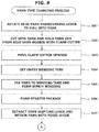
- FIG. 8 is a flowchart of the first half of the yarn-type changing process and FIG. 9 is a flowchart of the second half of the yarn-type changing process.
- FIGS. 10A to 10F are schematic side views for explaining an operation performed during the yarn-type changing process.
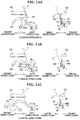
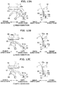
- FIGS. 11A to 11C and FIGS. 12A to 12C are schematic back views (left views) and side views (right views) for explaining an operation performed during the yarn-type changing process.
- FIGS. 13A to 13D are schematic side views for explaining an operation performed during the yarn-type changing process. Note that, in FIGS. 10A to 13D , some structural components have been appropriately omitted.
- FIG. 10A shows a state in which the various structural components of the doffing device 3 are in the standby position (initial position).
- the seed yarn Y pulled from the seed yarn bobbin 71 is held by the clamp cutter for seed yarn 73 after passing through the slit of the seed yarn transferring lever 72 and the notch of the guide for seed yarn 77.
- the doffing controlling section 3a drives the seed yarn transferring motor 76 to rotate the seed yarn transferring lever 72 horizontally.
- the seed yarn transferring lever 72 moves from the standby position to the pulling position allowing pulling of the seed yarn Y toward the winding unit 2 (Step S201).
- Step S204 After the seed yarn Y is cut, the seed yarn Y held by the clamp cutter for seed yarn 73 is released, and the yarn trap 74 is operated to suck yarn waste held by the clamp cutter for seed yarn 73 with the yarn trap 74. Then, the doffing controlling section 3a drives the chucker driving section 58 to set an empty winding tube Q on the cradle 41 (Step S204). Note that, it is allowable to appropriately change the contents of Steps S203 and S204. For example, it is allowable to perform a part of the processing of Step S203 and a part of the processing of Step S204 simultaneously.
- the doffing controlling section 3a drives the yarn shifting motor 63 to rotate the yarn shifting lever 62 horizontally to, as shown in FIG. 10D , hook the seed yarn Y present between the clamp cutter 51 and the tip end part of the seed yarn transferring lever 72 with the tip end part of the yarn shifting lever 62 and move the hooked seed yarn Y to the right side of the winding tube Q.
- the state shown in FIG. 7A is achieved.
- the seed yarn transferring lever 72 is returned to the standby position inside the openable-closable member 50a.
- the bunch winding is formed after fixing the seed yarn Y to the winding tube Q (Step S205). Because the operation performed at Step S205 is the same as that performed at Step S104 in the doffing process, a detained explanation of the operation performed at Step S205 will be omitted.
- the doffing controlling section 3a causes the traversing drum 42 to perform the normal rotation while slowly returning the yarn shifting lever 62 toward the standby position. Accordingly, as shown in FIG. 10E , a starter package SP in which the seed yarn Y has been wound on the winding tube Q is formed (Step S206). Then, the seed yarn Y present between the starter package SP and the seed yarn transferring lever 72 is moved by a transferring mechanism 9 arranged in the doffing device 3 near to the suction port 55a of the suction mouth 55 that is in the standby position.
- the transferring mechanism 9 is constituted by the yarn shifting lever 62, the fixed guide 64, and the yarn transferring lever 65. The normal rotation of the traversing drum 42 is stopped before the seed yarn Y is cut at Step S210.
- Step S207 When the yarn shifting lever 62 is rotated further toward the standby position, as shown in FIGS. 10F and 11A , the seed yarn Y is hooked with the retaining member 64a of the fixed guide 64 and retained (Step S207). In this state, the rotation of the yarn shifting lever 62 is once stopped, and then an operation to move the seed yarn Y near to the suction port 55a of the suction mouth 55 that is in the standby position is performed by using the yarn transferring lever 65. Such an operation is explained by referring to FIGS. 11A to 12C .
- the seed yarn Y present between the yarn shifting lever 62 and the fixed guide 64 spans over the yarn transferring lever 65 in the front-back direction, and a yarn path that passes on the left side of the yarn transferring lever 65 is formed.
- the doffing controlling section 3a drives the yarn transferring motor 66 to rotate the yarn transferring lever 65 clockwise when seen from the back direction.
- the seed yarn Y is pushed to the left lower side while the seed yarn Y has entered into the concave part 65c of the yarn transferring lever 65, and the seed yarn Y retained by the retaining member 64a is released (Step S208).
- the seed yarn Y that slips from the retaining member 64a of the fixed guide 64 and the concave part 65c of the yarn transferring lever 65 goes over a left end of the fixed guide 64 from the back direction to the front direction, and, as shown in FIG. 11C , passes through the notch of the guide for seed yarn 77 and the clamp cutter for seed yarn 73 and is put on a left hand side of the protruding member 64b of the fixed guide 64.
- the yarn transferring lever 65 is further rotated counterclockwise and makes approximately one rotation, as shown in FIG.
- the seed yarn Y contacts the convex part 65d of the yarn transferring lever 65, and as the yarn transferring lever 65 rotates further, the seed yarn Y moves above along an edge of the convex part 65d and finally goes into the hooking member 65b.
- the yarn transferring lever 65 is further rotated counterclockwise in the state in which the seed yarn Y has been hooked by the hooking member 65b, as shown in FIG. 12B , the seed yarn Y passes just in front of a central part of the suction port 55a of the suction mouth 55. At this point, the rotation of the yarn transferring lever 65 is once stopped. Because the seed yarn Y hooked by the hooking member 65b is pulled by the yarn transferring lever 65, just before attending the state shown in FIG. 12B , the seed yarn Y slips from the yarn shifting lever 62, and, with this, the yarn shifting lever 62 is returned to the standby position.
- Step S210 When the seed yarn Y is just in front of the suction port 55a, if the seed yarn Y is cut by the clamp cutter for seed yarn 73, as shown in FIG. 12C , the yarn end of the seed yarn Y from the starter package SP is sucked by the suction port 55a of the suction mouth 55, and this yarn end can be sucked and held with the suction mouth 55 (Step S210).
- the yarn transferring lever 65 is rotated clockwise when seen from the back direction only a little almost simultaneously with cutting the seed yarn Y with the clamp cutter for seed yarn 73.
- the doffing controlling section 3a drives the yarn flying motor 68 to rotate the yarn flying lever 67 in the back direction.
- the yarn picking member 67b of the yarn flying lever 67 picks the seed yarn Y that was moved downward by the yarn transferring lever 65, and, as shown in FIG. 13C , moves the seed yarn Y near to the suction port of the yarn passing nozzle 34 of the yarn accumulating device 30 (Step S213).
- the yarn transferring mechanism 8 which guides the yarn Y from the package P to the suction port of the yarn passing nozzle 34, is constituted by the yarn transferring lever 65 and the yarn flying lever 67.
- Steps S212 and S213 are equivalent to a "yarn transferring step" of the present invention.
- the yarn Y from the yarn supplying bobbin B subjected to the yarn joining by the yarn joining device 22 is all monitored with the yarn monitoring device 25 arranged downstream of the yarn joining device 22 so that the yarn Y can be removed when a yarn defect is found. Therefore, if the seed yarn Y wound on the seed yarn bobbin 71 is an inspected and non-defective product, the package P formed after the yarn-type changing process will have superior quality with no yarn Y having a yarn defect.
- Step S305 When the suction mouth 55 is returned to the standby position, the state shown in FIG. 13A is achieved. Then the yarn Y present between the package P and the suction mouth 55 is moved downward with the yarn transferring lever 65 (Step S305), and the yarn Y is guided with the yarn flying lever 67 near to the suction port of the yarn passing nozzle 34 (Step S306) . Steps S305 and S306 are equivalent to the "yarn transferring step" of the present invention.
- the yarn transferring mechanism 8 and the guiding mechanism 7 collaborate with each other whereby the process of guiding the yarn Y from the package P to the yarn joining device 22 after passing the yarn Y through the yarn accumulating device 30 can be automated. Accordingly, the time required to perform the yarn joining, therefore, the time to start (restart) the winding, can be shortened and the production efficiency of the package P can be improved.
- the doffing device 3 includes the seed yarn supplying section 70 for supplying a new type of the yarn Y in the yarn-type changing process
- the winding unit 2 forms the starter package SP by winding on the winding tube Q the seed yarn Y that is supplied from the seed yarn supplying section 70 in the yarn-type changing process
- the yarn Y from the starter package SP is guided to the yarn joining device 22 by the yarn transferring mechanism 8 and the guiding mechanism 7.
- the starter package SP is formed by using the seed yarn Y supplied from the seed yarn supplying section 70.
- the starter package SP can be prepared beforehand and set on the cradle 41, and thereafter the yarn-type changing process can be started.
Landscapes
- Engineering & Computer Science (AREA)
- Textile Engineering (AREA)
- Replacing, Conveying, And Pick-Finding For Filamentary Materials (AREA)
- Spinning Or Twisting Of Yarns (AREA)
Claims (14)
- Eine Garnwickelvorrichtung (1), die folgende Merkmale aufweist:eine Wickeleinheit (2), die ausgebildet ist, um ein Garn von einem Garnzuführabschnitt (10) zu ziehen und das Garn in einem Wickelabschnitt (40) auf eine Wickelröhre (Q) zu wickeln, so dass ein Wickelkörper (P) gebildet wird; undeine Abziehvorrichtung (3), die ausgebildet ist, um von der Wickeleinheit (2) einen Wickelkörper (P) abzuziehen, bei dem das Wickeln abgeschlossen wurde,wobei die Wickeleinheit (2) folgende Merkmale aufweist:eine Garnaneinanderfügungsvorrichtung (22), die in einer Garnbewegungsrichtung zwischen dem Garnzuführabschnitt (10) und dem Wickelabschnitt (40) angeordnet und ausgebildet ist, um ein Garn von dem Garnzuführabschnitt (10) und ein Garn von dem Wickelabschnitt (40) einem Garnaneinanderfügen zu unterziehen;eine Garnsammelvorrichtung (30), die in der Garnbewegungsrichtung zwischen der Garnaneinanderfügungsvorrichtung (22) und dem Wickelabschnitt (40) angeordnet und ausgebildet ist, um das Garn zu sammeln; undeinen Führungsmechanismus (7), der ausgebildet ist, um ein Garn von dem Wickelkörper (P) zu der Garnaneinanderfügungsvorrichtung (22) zu führen, nachdem das Garn durch die Garnsammelvorrichtung (30) gelaufen ist, wenn das Garn zwischen dem Wickelkörper (P) und der Garnsammelvorrichtung (30) unterbrochen wurde, unddadurch gekennzeichnet, dass:
die Abziehvorrichtung (3) einen Garnübertragungsmechanismus (8) aufweist, der ausgebildet ist, um das Garn von dem Wickelkörper (P), der sich in einer Rückwärtsrichtung dreht, die entgegengesetzt zu einer Richtung beim Wickeln des Garns ist, zu dem Führungsmechanismus (7) zu führen, wenn das Garn zwischen dem Wickelkörper (P) und der Garnsammelvorrichtung (30) unterbrochen wurde. - Die Garnwickelvorrichtung (1) gemäß Anspruch 1, die dadurch gekennzeichnet ist, dass:die Abziehvorrichtung (3) einen Ursprungsgarnzuführabschnitt (70) aufweist, der ausgebildet ist, um einen neuen Typ des Garns in einem Garntyp-Änderungsvorgang zum Verändern eines Typs des Garns zuzuführen, das in dem Wickelabschnitt (40) gewickelt werden soll,die Wickeleinheit (2) ausgebildet ist, um bei dem Garntyp-Änderungsvorgang einen Anfangswickelkörper (P) zu bilden, der der Wickelkörper (P) ist, bei dem das Garn, das von dem Ursprungsgarnzuführabschnitt (70) zugeführt wird, auf die Wickelröhre (Q) gewickelt wurde, undder Garnübertragungsmechanismus (8) und der Führungsmechanismus (7) ausgebildet sind, um das Garn von dem Anfangswickelkörper (P) zu der Garnaneinanderfügungsvorrichtung (22) zu führen.
- Die Garnwickelvorrichtung (1) gemäß Anspruch 2, die dadurch gekennzeichnet ist, dass die Abziehvorrichtung (3) folgende Merkmale aufweist:ein Ansaughaltebauteil (55) mit einer Ansaugöffnung (55a), das ausgebildet ist, um das Garn anzusaugen und zu halten;einen Übertragungsmechanismus (9), der ausgebildet ist, um das Garn, das zwischen dem Anfangswickelkörper (P) und dem Ursprungsgarnzuführabschnitt (70) vorliegt, zu einer ersten Position relativ zu der Ansaugöffnung (55a) zu bewegen, nachdem der Anfangswickelkörper (P) gebildet wurde, so dass das Garn (Y) mit der Ansaugöffnung (55a) angesaugt werden kann; undein Garnabschneidebauteil (73), das ausgebildet ist, um das Garn, das durch den Übertragungsmechanismus (9) zu der ersten Position relativ zu der Ansaugöffnung (55a) bewegt wurde, an einem Punkt abzuschneiden, der näher an dem Ursprungsgarnzuführabschnitt (70) liegt als die Ansaugöffnung (55a).
- Die Garnwickelvorrichtung (1) gemäß Anspruch 3, die dadurch gekennzeichnet ist, dass
das Ansaughaltebauteil (55) ausgebildet ist, um sich zwischen einer Standby-Position und einer Nahposition zu bewegen, in der sich die Ansaugöffnung (55a) an dem Wickelkörper (P) befindet, und
der Übertragungsmechanismus (9) ausgebildet ist, um das Garn, das zwischen dem Anfangswickelkörper (P) und dem Ursprungsgarnzuführabschnitt (70) vorliegt, zu der ersten Position relativ zu der Ansaugöffnung (55a) des Ansaughaltebauteils (55) zu bewegen, das sich in der Standby-Position befindet. - Die Garnwickelvorrichtung (1) gemäß Anspruch 4, die dadurch gekennzeichnet ist, dass der Übertragungsmechanismus (9) ein Garnübertragungsbauteil (65) aufweist, das ausgebildet ist, um das Garn zu der ersten Position relativ zu der Ansaugöffnung (55a) des Ansaughaltebauteils (55) zu bewegen, das sich in der Standby-Position befindet, nachdem das Garn, das zwischen dem Anfangswickelkörper (P) und dem Ursprungsgarnzuführabschnitt (70) vorliegt, eingehakt wurde.
- Die Garnwickelvorrichtung (1) gemäß Anspruch 5, die dadurch gekennzeichnet ist, dass der Übertragungsmechanismus (9) ferner eine fixierte Führung (64) aufweist, die ausgebildet ist, um das Garn, das zwischen dem Anfangswickelkörper (P) und dem Ursprungsgarnzuführabschnitt (70) vorliegt, zu halten, bevor das Garn, das zwischen dem Anfangswickelkörper (P) und dem Ursprungsgarnzuführabschnitt (70) vorliegt, mit dem Garnübertragungsbauteil (65) bewegt wird.
- Die Garnwickelvorrichtung (1) gemäß Anspruch 6, die dadurch gekennzeichnet ist, dass das Garnübertragungsbauteil (65) nach einem Lösen des Haltens des Garns durch die fixierte Führung (64) durch Bewegen in eine vorbestimmte Richtung ausgebildet ist, um sich in einer entgegengesetzten Richtung zu der vorbestimmten Richtung zu bewegen, um das Garn einzuhaken und das Garn zu der ersten Position relativ zu der Ansaugöffnung (55a) des Ansaughaltebauteils (55) zu bewegen, das sich in der Standby-Position befindet.
- Die Garnwickelvorrichtung (1) gemäß einem der Ansprüche 5 bis 7, die dadurch gekennzeichnet ist, dass das Garnübertragungsbauteil (65) eine Komponente des Garnübertragungsmechanismus (8) ist und das Garnübertragungsbauteil (65) ausgebildet ist, um das Garn von dem Anfangswickelkörper (P) einzuhaken, das mit dem Ansaughaltebauteil (55) angesaugt und gehalten wird, das sich in der Standby-Position befindet, und das Garn bewegen kann.
- Die Garnwickelvorrichtung (1) gemäß einem der Ansprüche 4 bis 8, die dadurch gekennzeichnet ist, dass, wenn das Garn zwischen dem Wickelkörper (P) und der Garnsammelvorrichtung (30) entzwei ist, wenn ein Oberes-Garn-Abschneidevorgang durchgeführt wird, bei dem die Garne einem Garnaneinanderfügen durch die Garnaneinanderfügungsvorrichtung (22) unterzogen werden, das Ansaughaltebauteil (55) ausgebildet ist, um das Garn von dem Wickelkörper (P) anzusaugen und zu halten, nachdem dasselbe aus der Standby-Position in die Nahposition bewegt wurde.
- Die Garnwickelvorrichtung (1) gemäß Anspruch 9, die dadurch gekennzeichnet ist, dass bei dem Oberes-Garn-Abschneidevorgang das Ansaughaltebauteil (55) ausgebildet ist, um sich mit dem angesaugten und gehaltenen Garn in die Standby-Position zu bewegen, nachdem das Garn von dem Wickelkörper (P) an der Nahposition angesaugt und gehalten wurde.
- Die Garnwickelvorrichtung (1) gemäß einem der Ansprüche 2 bis 10, die dadurch gekennzeichnet ist, dass:die Abziehvorrichtung (3) einen Garnhalte- und Abschneideabschnitt (51) aufweist, der ausgebildet ist, um das Garn, das zwischen dem Wickelkörper (P) und der Garnsammelvorrichtung (30) vorliegt, zu halten und abzuschneiden, wenn ein Abziehvorgang eines Abziehens des Wickelkörpers (P) durchgeführt wird, bei dem das Wickeln abgeschlossen wurde, undder Ursprungsgarnzuführabschnitt (70) ein Ursprungsgarnübertragungsbauteil (72) aufweist, das ausgebildet ist, um den neuen Typ von Garn in eine Position zu ziehen, an der das Garn mit dem Garnhalte- und Abschneideabschnitt (51) gehalten werden soll.
- Ein Garnaneinanderfügungsverfahren zum Aneinanderfügen von Garnen in einer Garnwickelvorrichtung (1), wenn ein Garn zwischen einem Wickelkörper (P) und einer Garnsammelvorrichtung (30) unterbrochen wurde,
wobei die Garnwickelvorrichtung (1) folgende Merkmale aufweist:eine Wickeleinheit (2), die ausgebildet ist, um den Wickelkörper (P) zu bilden durch Wickeln des Garns auf eine Wickelröhre (Q) in einem Wickelabschnitt (40) nach einem zeitweiligen Sammeln des Garns, das von einem Garnzuführabschnitt (10) gezogen wird, in der Garnsammelvorrichtung (30), und die eine Garnaneinanderfügungsvorrichtung (22) aufweist, die in einer Garnbewegungsrichtung zwischen dem Garnzuführabschnitt (10) und der Garnsammelvorrichtung (30) angeordnet ist und ausgebildet ist, um ein Garn von dem Garnzuführabschnitt (10) und ein Garn von dem Wickelabschnitt (40) einem Garnaneinanderfügen zu unterziehen; undeine Abziehvorrichtung (3), die ausgebildet ist, um einen Wickelkörper (P), bei dem das Wickeln abgeschlossen wurde, von der Wickeleinheit (2) abzuziehen,wobei das Garnaneinanderfügungsverfahren folgende Schritte aufweist:einen Garnübertragungsschritt eines Führens des Garns von dem Wickelkörper (P) mit einem Garnübertragungsmechanismus (8), der in der Abziehvorrichtung (3) angeordnet ist, zu der Garnsammelvorrichtung (30), während sich der Wickelkörper (P) in einer Rückwärtsrichtung dreht, die entgegengesetzt zu einer Richtung beim Wickeln des Garns ist;einen Führungsschritt eines Führens des Garns mit einem Führungsmechanismus (7), der in der Wickeleinheit (2) angeordnet ist, von dem Wickelkörper (P), der zu der Garnsammelvorrichtung (30) geführt wurde, zu der Garnaneinanderfügungsvorrichtung (22), nachdem das Garn durch die Garnsammelvorrichtung (30) gelaufen ist; undeinen Garnaneinanderfügungsschritt eines Unterziehens des Garns von dem Wickelkörper (P), und das zu der Garnaneinanderfügungsvorrichtung (22) geführt wird, und des Garns von dem Garnzuführabschnitt (10) gegenüber einem Garnaneinanderfügen durch die Garnaneinanderfügungsvorrichtung (22). - Das Garnaneinanderfügungsverfahren gemäß Anspruch 12, das ferner folgende Schritte aufweist:einen Anfangswickelkörperbildungsschritt, bei dem beim Durchführen eines Garntypänderungsvorgangs eines Veränderns eines Typs des Garns, das in dem Wickelabschnitt (40) gewickelt werden soll, die Wickeleinheit (2) eine Zuführung eines neuen Typs des Garns von einem Ursprungsgarnzuführabschnitt (70), der in der Abziehvorrichtung (3) angeordnet ist, aufnimmt und einen Anfangswickelkörper (P) bildet, der der Wickelkörper (P) ist, bei dem der neue Typ des Garns auf die Wickelröhre (Q) gewickelt wurde; undeinen Ausführungsschritt eines Ausführens des Garnübertragungsschritts, des Führungsschritts und des Garnaneinanderfügungsschritts in Bezug auf das Garn, das zwischen dem Anfangswickelkörper (P) und dem Ursprungsgarnzuführabschnitt (70) vorliegt.
- Das Garnaneinanderfügungsverfahren gemäß Anspruch 12 oder 13, das ferner folgende Schritte aufweist:einen Ansaug- und Halteschritt, bei dem, wenn das Garn zwischen den Wickelkörper (P) und der Garnsammelvorrichtung (30) entzwei ist, das Garn von dem Wickelkörper (P) mit einem Ansaughaltebauteil (55), das in der Abziehvorrichtung (3) angeordnet ist, bei einem Oberes-Garn-Abschneidevorgang angesaugt und gehalten wird, bei dem die Garne dem Garnaneinanderfügen durch die Garnaneinanderfügungsvorrichtung (22) unterzogen werden; undeinen Ausführungsschritt eines Ausführens des Garnübertragungsschritts, des Führungsschritts und des Garnaneinanderfügungsschritts in Bezug auf das Garn, das zwischen dem Wickelkörper (P) und dem Ansaughaltebauteil (55) vorliegt.
Applications Claiming Priority (1)
| Application Number | Priority Date | Filing Date | Title |
|---|---|---|---|
| JP2016205406A JP2018065659A (ja) | 2016-10-19 | 2016-10-19 | 糸巻取装置及び糸継方法 |
Publications (2)
| Publication Number | Publication Date |
|---|---|
| EP3312117A1 EP3312117A1 (de) | 2018-04-25 |
| EP3312117B1 true EP3312117B1 (de) | 2019-08-14 |
Family
ID=60119937
Family Applications (1)
| Application Number | Title | Priority Date | Filing Date |
|---|---|---|---|
| EP17196775.5A Active EP3312117B1 (de) | 2016-10-19 | 2017-10-17 | Garnwicklungsvorrichtung und garnverbindungsverfahren |
Country Status (3)
| Country | Link |
|---|---|
| EP (1) | EP3312117B1 (de) |
| JP (1) | JP2018065659A (de) |
| CN (1) | CN107963518B (de) |
Families Citing this family (4)
| Publication number | Priority date | Publication date | Assignee | Title |
|---|---|---|---|---|
| EP3865441B1 (de) * | 2018-10-09 | 2023-07-12 | TMT Machinery, Inc. | Garnwicklungsmaschine |
| JP2024168618A (ja) | 2023-05-24 | 2024-12-05 | 村田機械株式会社 | 糸処理装置 |
| JP2024168596A (ja) | 2023-05-24 | 2024-12-05 | 村田機械株式会社 | 糸巻取機 |
| JP2024172173A (ja) | 2023-05-31 | 2024-12-12 | 村田機械株式会社 | 玉揚装置 |
Family Cites Families (8)
| Publication number | Priority date | Publication date | Assignee | Title |
|---|---|---|---|---|
| JPH02243475A (ja) * | 1989-03-17 | 1990-09-27 | Murata Mach Ltd | 自動ワインダにおける異常警報装置 |
| JP2006225092A (ja) * | 2005-02-16 | 2006-08-31 | Murata Mach Ltd | 自動玉揚げ動作方法 |
| ITMI20050629A1 (it) * | 2005-04-13 | 2006-10-14 | Savio Macchine Tessili Spa | Dispositivo e procedimento per la manipolazione e il controllo del filo in una testa di roccatura di una macchina roccatrice nelle operazioni di levata di una rocca |
| JP2010174405A (ja) * | 2009-01-29 | 2010-08-12 | Murata Machinery Ltd | 糸端捕捉案内装置及びそれを備える紡績機 |
| JP2015000777A (ja) * | 2013-06-13 | 2015-01-05 | 村田機械株式会社 | 糸巻取機 |
| JP2015148035A (ja) * | 2014-02-10 | 2015-08-20 | 村田機械株式会社 | 糸捕捉装置、及び、糸巻取機 |
| JP2016044016A (ja) * | 2014-08-21 | 2016-04-04 | 村田機械株式会社 | 糸巻取装置及び自動ワインダ |
| JP2016047764A (ja) * | 2014-08-28 | 2016-04-07 | 村田機械株式会社 | 糸巻取装置及び糸巻取機 |
-
2016
- 2016-10-19 JP JP2016205406A patent/JP2018065659A/ja active Pending
-
2017
- 2017-09-30 CN CN201710914897.2A patent/CN107963518B/zh active Active
- 2017-10-17 EP EP17196775.5A patent/EP3312117B1/de active Active
Non-Patent Citations (1)
| Title |
|---|
| None * |
Also Published As
| Publication number | Publication date |
|---|---|
| CN107963518B (zh) | 2021-02-09 |
| JP2018065659A (ja) | 2018-04-26 |
| EP3312117A1 (de) | 2018-04-25 |
| CN107963518A (zh) | 2018-04-27 |
Similar Documents
| Publication | Publication Date | Title |
|---|---|---|
| JP6180809B2 (ja) | エアジェット紡績機およびその作動方法 | |
| EP3312117B1 (de) | Garnwicklungsvorrichtung und garnverbindungsverfahren | |
| EP2345611B1 (de) | Garnwickelmaschine und Garnführungsverfahren | |
| JP2016047764A (ja) | 糸巻取装置及び糸巻取機 | |
| EP2345612A2 (de) | Abziehvorrichtung | |
| JP5471923B2 (ja) | 糸巻取装置 | |
| EP2905249B1 (de) | Spuleneinstellungsvorrichtung und Garnwickelmaschine | |
| CN104911755A (zh) | 纺纱机和将纱线传送至接纱装置的方法 | |
| EP2990367B1 (de) | Garnwickelvorrichtung | |
| JP2014125714A (ja) | 紡績機 | |
| EP3312116B1 (de) | Garnaufwicklungsvorrichtung und paketrotationsstoppverfahren | |
| JP2015101453A (ja) | ボビン保持装置、ボビンセット装置及び糸巻取機 | |
| JP2016016959A (ja) | 糸巻取機及び糸巻取方法 | |
| JP2016137959A (ja) | 糸巻取機 | |
| CZ2007637A3 (cs) | Obslužné zarízení tryskového doprádacího stroje a zpusoby manipulace s prízí na pracovním míste tryskového doprádacího stroje | |
| CN116803878A (zh) | 纱线卷取机以及纱线卷取方法 | |
| EP4467497B1 (de) | Garnwickler | |
| JP2017077949A (ja) | 糸巻取装置 | |
| EP4112521B1 (de) | Garnwicklungsmaschine | |
| CN115467055B (zh) | 纺纱机 | |
| CN116891164A (zh) | 纱线卷取机以及纱线卷取方法 | |
| JPH10297826A (ja) | 自動ワインダ及びその玉揚装置 | |
| JP2015044689A (ja) | 玉揚装置及び糸巻取機 | |
| JP2026025358A (ja) | 糸巻取システム | |
| JP2024172173A (ja) | 玉揚装置 |
Legal Events
| Date | Code | Title | Description |
|---|---|---|---|
| PUAI | Public reference made under article 153(3) epc to a published international application that has entered the european phase |
Free format text: ORIGINAL CODE: 0009012 |
|
| STAA | Information on the status of an ep patent application or granted ep patent |
Free format text: STATUS: THE APPLICATION HAS BEEN PUBLISHED |
|
| AK | Designated contracting states |
Kind code of ref document: A1 Designated state(s): AL AT BE BG CH CY CZ DE DK EE ES FI FR GB GR HR HU IE IS IT LI LT LU LV MC MK MT NL NO PL PT RO RS SE SI SK SM TR |
|
| AX | Request for extension of the european patent |
Extension state: BA ME |
|
| STAA | Information on the status of an ep patent application or granted ep patent |
Free format text: STATUS: REQUEST FOR EXAMINATION WAS MADE |
|
| 17P | Request for examination filed |
Effective date: 20180917 |
|
| RBV | Designated contracting states (corrected) |
Designated state(s): AL AT BE BG CH CY CZ DE DK EE ES FI FR GB GR HR HU IE IS IT LI LT LU LV MC MK MT NL NO PL PT RO RS SE SI SK SM TR |
|
| GRAP | Despatch of communication of intention to grant a patent |
Free format text: ORIGINAL CODE: EPIDOSNIGR1 |
|
| STAA | Information on the status of an ep patent application or granted ep patent |
Free format text: STATUS: GRANT OF PATENT IS INTENDED |
|
| INTG | Intention to grant announced |
Effective date: 20190221 |
|
| GRAS | Grant fee paid |
Free format text: ORIGINAL CODE: EPIDOSNIGR3 |
|
| GRAA | (expected) grant |
Free format text: ORIGINAL CODE: 0009210 |
|
| STAA | Information on the status of an ep patent application or granted ep patent |
Free format text: STATUS: THE PATENT HAS BEEN GRANTED |
|
| AK | Designated contracting states |
Kind code of ref document: B1 Designated state(s): AL AT BE BG CH CY CZ DE DK EE ES FI FR GB GR HR HU IE IS IT LI LT LU LV MC MK MT NL NO PL PT RO RS SE SI SK SM TR |
|
| REG | Reference to a national code |
Ref country code: GB Ref legal event code: FG4D |
|
| REG | Reference to a national code |
Ref country code: CH Ref legal event code: EP Ref country code: AT Ref legal event code: REF Ref document number: 1166773 Country of ref document: AT Kind code of ref document: T Effective date: 20190815 |
|
| REG | Reference to a national code |
Ref country code: IE Ref legal event code: FG4D |
|
| REG | Reference to a national code |
Ref country code: DE Ref legal event code: R096 Ref document number: 602017006099 Country of ref document: DE |
|
| REG | Reference to a national code |
Ref country code: NL Ref legal event code: MP Effective date: 20190814 |
|
| REG | Reference to a national code |
Ref country code: LT Ref legal event code: MG4D |
|
| PG25 | Lapsed in a contracting state [announced via postgrant information from national office to epo] |
Ref country code: FI Free format text: LAPSE BECAUSE OF FAILURE TO SUBMIT A TRANSLATION OF THE DESCRIPTION OR TO PAY THE FEE WITHIN THE PRESCRIBED TIME-LIMIT Effective date: 20190814 Ref country code: NO Free format text: LAPSE BECAUSE OF FAILURE TO SUBMIT A TRANSLATION OF THE DESCRIPTION OR TO PAY THE FEE WITHIN THE PRESCRIBED TIME-LIMIT Effective date: 20191114 Ref country code: NL Free format text: LAPSE BECAUSE OF FAILURE TO SUBMIT A TRANSLATION OF THE DESCRIPTION OR TO PAY THE FEE WITHIN THE PRESCRIBED TIME-LIMIT Effective date: 20190814 Ref country code: SE Free format text: LAPSE BECAUSE OF FAILURE TO SUBMIT A TRANSLATION OF THE DESCRIPTION OR TO PAY THE FEE WITHIN THE PRESCRIBED TIME-LIMIT Effective date: 20190814 Ref country code: LT Free format text: LAPSE BECAUSE OF FAILURE TO SUBMIT A TRANSLATION OF THE DESCRIPTION OR TO PAY THE FEE WITHIN THE PRESCRIBED TIME-LIMIT Effective date: 20190814 Ref country code: BG Free format text: LAPSE BECAUSE OF FAILURE TO SUBMIT A TRANSLATION OF THE DESCRIPTION OR TO PAY THE FEE WITHIN THE PRESCRIBED TIME-LIMIT Effective date: 20191114 Ref country code: PT Free format text: LAPSE BECAUSE OF FAILURE TO SUBMIT A TRANSLATION OF THE DESCRIPTION OR TO PAY THE FEE WITHIN THE PRESCRIBED TIME-LIMIT Effective date: 20191216 Ref country code: HR Free format text: LAPSE BECAUSE OF FAILURE TO SUBMIT A TRANSLATION OF THE DESCRIPTION OR TO PAY THE FEE WITHIN THE PRESCRIBED TIME-LIMIT Effective date: 20190814 |
|
| REG | Reference to a national code |
Ref country code: AT Ref legal event code: MK05 Ref document number: 1166773 Country of ref document: AT Kind code of ref document: T Effective date: 20190814 |
|
| PG25 | Lapsed in a contracting state [announced via postgrant information from national office to epo] |
Ref country code: AL Free format text: LAPSE BECAUSE OF FAILURE TO SUBMIT A TRANSLATION OF THE DESCRIPTION OR TO PAY THE FEE WITHIN THE PRESCRIBED TIME-LIMIT Effective date: 20190814 Ref country code: GR Free format text: LAPSE BECAUSE OF FAILURE TO SUBMIT A TRANSLATION OF THE DESCRIPTION OR TO PAY THE FEE WITHIN THE PRESCRIBED TIME-LIMIT Effective date: 20191115 Ref country code: RS Free format text: LAPSE BECAUSE OF FAILURE TO SUBMIT A TRANSLATION OF THE DESCRIPTION OR TO PAY THE FEE WITHIN THE PRESCRIBED TIME-LIMIT Effective date: 20190814 Ref country code: LV Free format text: LAPSE BECAUSE OF FAILURE TO SUBMIT A TRANSLATION OF THE DESCRIPTION OR TO PAY THE FEE WITHIN THE PRESCRIBED TIME-LIMIT Effective date: 20190814 Ref country code: IS Free format text: LAPSE BECAUSE OF FAILURE TO SUBMIT A TRANSLATION OF THE DESCRIPTION OR TO PAY THE FEE WITHIN THE PRESCRIBED TIME-LIMIT Effective date: 20191214 |
|
| PG25 | Lapsed in a contracting state [announced via postgrant information from national office to epo] |
Ref country code: TR Free format text: LAPSE BECAUSE OF FAILURE TO SUBMIT A TRANSLATION OF THE DESCRIPTION OR TO PAY THE FEE WITHIN THE PRESCRIBED TIME-LIMIT Effective date: 20190814 |
|
| PG25 | Lapsed in a contracting state [announced via postgrant information from national office to epo] |
Ref country code: PL Free format text: LAPSE BECAUSE OF FAILURE TO SUBMIT A TRANSLATION OF THE DESCRIPTION OR TO PAY THE FEE WITHIN THE PRESCRIBED TIME-LIMIT Effective date: 20190814 Ref country code: DK Free format text: LAPSE BECAUSE OF FAILURE TO SUBMIT A TRANSLATION OF THE DESCRIPTION OR TO PAY THE FEE WITHIN THE PRESCRIBED TIME-LIMIT Effective date: 20190814 Ref country code: AT Free format text: LAPSE BECAUSE OF FAILURE TO SUBMIT A TRANSLATION OF THE DESCRIPTION OR TO PAY THE FEE WITHIN THE PRESCRIBED TIME-LIMIT Effective date: 20190814 Ref country code: EE Free format text: LAPSE BECAUSE OF FAILURE TO SUBMIT A TRANSLATION OF THE DESCRIPTION OR TO PAY THE FEE WITHIN THE PRESCRIBED TIME-LIMIT Effective date: 20190814 Ref country code: RO Free format text: LAPSE BECAUSE OF FAILURE TO SUBMIT A TRANSLATION OF THE DESCRIPTION OR TO PAY THE FEE WITHIN THE PRESCRIBED TIME-LIMIT Effective date: 20190814 |
|
| PG25 | Lapsed in a contracting state [announced via postgrant information from national office to epo] |
Ref country code: CZ Free format text: LAPSE BECAUSE OF FAILURE TO SUBMIT A TRANSLATION OF THE DESCRIPTION OR TO PAY THE FEE WITHIN THE PRESCRIBED TIME-LIMIT Effective date: 20190814 Ref country code: SK Free format text: LAPSE BECAUSE OF FAILURE TO SUBMIT A TRANSLATION OF THE DESCRIPTION OR TO PAY THE FEE WITHIN THE PRESCRIBED TIME-LIMIT Effective date: 20190814 Ref country code: MC Free format text: LAPSE BECAUSE OF FAILURE TO SUBMIT A TRANSLATION OF THE DESCRIPTION OR TO PAY THE FEE WITHIN THE PRESCRIBED TIME-LIMIT Effective date: 20190814 Ref country code: SM Free format text: LAPSE BECAUSE OF FAILURE TO SUBMIT A TRANSLATION OF THE DESCRIPTION OR TO PAY THE FEE WITHIN THE PRESCRIBED TIME-LIMIT Effective date: 20190814 Ref country code: IS Free format text: LAPSE BECAUSE OF FAILURE TO SUBMIT A TRANSLATION OF THE DESCRIPTION OR TO PAY THE FEE WITHIN THE PRESCRIBED TIME-LIMIT Effective date: 20200224 |
|
| REG | Reference to a national code |
Ref country code: DE Ref legal event code: R097 Ref document number: 602017006099 Country of ref document: DE |
|
| PLBE | No opposition filed within time limit |
Free format text: ORIGINAL CODE: 0009261 |
|
| STAA | Information on the status of an ep patent application or granted ep patent |
Free format text: STATUS: NO OPPOSITION FILED WITHIN TIME LIMIT |
|
| PG2D | Information on lapse in contracting state deleted |
Ref country code: IS |
|
| PG25 | Lapsed in a contracting state [announced via postgrant information from national office to epo] |
Ref country code: LU Free format text: LAPSE BECAUSE OF NON-PAYMENT OF DUE FEES Effective date: 20191017 |
|
| 26N | No opposition filed |
Effective date: 20200603 |
|
| REG | Reference to a national code |
Ref country code: BE Ref legal event code: MM Effective date: 20191031 |
|
| PG25 | Lapsed in a contracting state [announced via postgrant information from national office to epo] |
Ref country code: SI Free format text: LAPSE BECAUSE OF FAILURE TO SUBMIT A TRANSLATION OF THE DESCRIPTION OR TO PAY THE FEE WITHIN THE PRESCRIBED TIME-LIMIT Effective date: 20190814 Ref country code: BE Free format text: LAPSE BECAUSE OF NON-PAYMENT OF DUE FEES Effective date: 20191031 |
|
| PG25 | Lapsed in a contracting state [announced via postgrant information from national office to epo] |
Ref country code: FR Free format text: LAPSE BECAUSE OF NON-PAYMENT OF DUE FEES Effective date: 20191031 Ref country code: IE Free format text: LAPSE BECAUSE OF NON-PAYMENT OF DUE FEES Effective date: 20191017 Ref country code: ES Free format text: LAPSE BECAUSE OF FAILURE TO SUBMIT A TRANSLATION OF THE DESCRIPTION OR TO PAY THE FEE WITHIN THE PRESCRIBED TIME-LIMIT Effective date: 20190814 |
|
| PG25 | Lapsed in a contracting state [announced via postgrant information from national office to epo] |
Ref country code: CY Free format text: LAPSE BECAUSE OF FAILURE TO SUBMIT A TRANSLATION OF THE DESCRIPTION OR TO PAY THE FEE WITHIN THE PRESCRIBED TIME-LIMIT Effective date: 20190814 |
|
| REG | Reference to a national code |
Ref country code: CH Ref legal event code: PL |
|
| PG25 | Lapsed in a contracting state [announced via postgrant information from national office to epo] |
Ref country code: LI Free format text: LAPSE BECAUSE OF FAILURE TO SUBMIT A TRANSLATION OF THE DESCRIPTION OR TO PAY THE FEE WITHIN THE PRESCRIBED TIME-LIMIT Effective date: 20201031 Ref country code: CH Free format text: LAPSE BECAUSE OF FAILURE TO SUBMIT A TRANSLATION OF THE DESCRIPTION OR TO PAY THE FEE WITHIN THE PRESCRIBED TIME-LIMIT Effective date: 20201031 |
|
| PG25 | Lapsed in a contracting state [announced via postgrant information from national office to epo] |
Ref country code: HU Free format text: LAPSE BECAUSE OF FAILURE TO SUBMIT A TRANSLATION OF THE DESCRIPTION OR TO PAY THE FEE WITHIN THE PRESCRIBED TIME-LIMIT; INVALID AB INITIO Effective date: 20171017 Ref country code: MT Free format text: LAPSE BECAUSE OF FAILURE TO SUBMIT A TRANSLATION OF THE DESCRIPTION OR TO PAY THE FEE WITHIN THE PRESCRIBED TIME-LIMIT Effective date: 20190814 |
|
| GBPC | Gb: european patent ceased through non-payment of renewal fee |
Effective date: 20211017 |
|
| PG25 | Lapsed in a contracting state [announced via postgrant information from national office to epo] |
Ref country code: MK Free format text: LAPSE BECAUSE OF FAILURE TO SUBMIT A TRANSLATION OF THE DESCRIPTION OR TO PAY THE FEE WITHIN THE PRESCRIBED TIME-LIMIT Effective date: 20190814 |
|
| PG25 | Lapsed in a contracting state [announced via postgrant information from national office to epo] |
Ref country code: GB Free format text: LAPSE BECAUSE OF NON-PAYMENT OF DUE FEES Effective date: 20211017 |
|
| PGFP | Annual fee paid to national office [announced via postgrant information from national office to epo] |
Ref country code: IT Payment date: 20250923 Year of fee payment: 9 |
|
| PGFP | Annual fee paid to national office [announced via postgrant information from national office to epo] |
Ref country code: DE Payment date: 20250923 Year of fee payment: 9 |