EP3312564A1 - Dispositif de détection d'angle de rotation et détecteur d'angle utilisé en son sein - Google Patents
Dispositif de détection d'angle de rotation et détecteur d'angle utilisé en son sein Download PDFInfo
- Publication number
- EP3312564A1 EP3312564A1 EP16194928.4A EP16194928A EP3312564A1 EP 3312564 A1 EP3312564 A1 EP 3312564A1 EP 16194928 A EP16194928 A EP 16194928A EP 3312564 A1 EP3312564 A1 EP 3312564A1
- Authority
- EP
- European Patent Office
- Prior art keywords
- yokes
- face
- permanent magnet
- magnetic
- rotational
- Prior art date
- Legal status (The legal status is an assumption and is not a legal conclusion. Google has not performed a legal analysis and makes no representation as to the accuracy of the status listed.)
- Granted
Links
- 238000001514 detection method Methods 0.000 claims abstract description 60
- 230000004907 flux Effects 0.000 claims abstract description 56
- 230000005415 magnetization Effects 0.000 claims abstract description 11
- 238000000465 moulding Methods 0.000 claims description 7
- 230000008859 change Effects 0.000 description 7
- 238000010586 diagram Methods 0.000 description 6
- 230000000694 effects Effects 0.000 description 6
- XEEYBQQBJWHFJM-UHFFFAOYSA-N Iron Chemical compound [Fe] XEEYBQQBJWHFJM-UHFFFAOYSA-N 0.000 description 5
- 238000004519 manufacturing process Methods 0.000 description 5
- 230000007246 mechanism Effects 0.000 description 5
- 230000004048 modification Effects 0.000 description 4
- 238000012986 modification Methods 0.000 description 4
- 238000011109 contamination Methods 0.000 description 3
- 238000009434 installation Methods 0.000 description 3
- 238000000034 method Methods 0.000 description 3
- 230000008569 process Effects 0.000 description 3
- 230000004308 accommodation Effects 0.000 description 2
- 229910052742 iron Inorganic materials 0.000 description 2
- 239000000463 material Substances 0.000 description 2
- 238000005259 measurement Methods 0.000 description 2
- 238000007789 sealing Methods 0.000 description 2
- 230000035945 sensitivity Effects 0.000 description 2
- 229910052779 Neodymium Inorganic materials 0.000 description 1
- 230000005540 biological transmission Effects 0.000 description 1
- 230000015572 biosynthetic process Effects 0.000 description 1
- 239000000696 magnetic material Substances 0.000 description 1
- 230000005389 magnetism Effects 0.000 description 1
- 239000007769 metal material Substances 0.000 description 1
- 239000000843 powder Substances 0.000 description 1
- 229910052761 rare earth metal Inorganic materials 0.000 description 1
- 150000002910 rare earth metals Chemical class 0.000 description 1
- 239000011347 resin Substances 0.000 description 1
- 229920005989 resin Polymers 0.000 description 1
- 239000000126 substance Substances 0.000 description 1
Images



Classifications
-
- G—PHYSICS
- G01—MEASURING; TESTING
- G01D—MEASURING NOT SPECIALLY ADAPTED FOR A SPECIFIC VARIABLE; ARRANGEMENTS FOR MEASURING TWO OR MORE VARIABLES NOT COVERED IN A SINGLE OTHER SUBCLASS; TARIFF METERING APPARATUS; MEASURING OR TESTING NOT OTHERWISE PROVIDED FOR
- G01D5/00—Mechanical means for transferring the output of a sensing member; Means for converting the output of a sensing member to another variable where the form or nature of the sensing member does not constrain the means for converting; Transducers not specially adapted for a specific variable
- G01D5/12—Mechanical means for transferring the output of a sensing member; Means for converting the output of a sensing member to another variable where the form or nature of the sensing member does not constrain the means for converting; Transducers not specially adapted for a specific variable using electric or magnetic means
- G01D5/14—Mechanical means for transferring the output of a sensing member; Means for converting the output of a sensing member to another variable where the form or nature of the sensing member does not constrain the means for converting; Transducers not specially adapted for a specific variable using electric or magnetic means influencing the magnitude of a current or voltage
- G01D5/142—Mechanical means for transferring the output of a sensing member; Means for converting the output of a sensing member to another variable where the form or nature of the sensing member does not constrain the means for converting; Transducers not specially adapted for a specific variable using electric or magnetic means influencing the magnitude of a current or voltage using Hall-effect devices
- G01D5/145—Mechanical means for transferring the output of a sensing member; Means for converting the output of a sensing member to another variable where the form or nature of the sensing member does not constrain the means for converting; Transducers not specially adapted for a specific variable using electric or magnetic means influencing the magnitude of a current or voltage using Hall-effect devices influenced by the relative movement between the Hall device and magnetic fields
Definitions
- the present invention relates to a rotational angle detecting device for detecting a rotational angle of a detected object, and an angle sensor unit used therein.
- a rotational angle detecting device is used for shift position detection of an automatic transmission and depression angle detection of an accelerator pedal or a brake pedal for a vehicle, and in recent years a magnetic type thereof adapted for severe in-vehicle environments such as vibrations, temperature changes and dusts has been increasingly in demand.
- Japanese Patent No. 5131537 discloses a conventional rotational angle detecting device of a magnetic type configured of a rotational member on the periphery of a rotational center of which permanent magnets are arranged to alternate an N pole region thereof with an S pole region thereof, and a plate-shaped magnetic plate and magnetic detection elements arranged in a predetermined position to the rotational member, wherein a rotational angle of the rotational member is calculated based upon the detection result of magnetic field components in two directions in the magnetic plate.
- the angle sensor unit accommodated in a case and formed as a one-piece product is internally required to air-tightly form a space accommodating the rotational member and hold the rotational member with good positional accuracy. Therefore the angle sensor unit is difficult to be miniaturized and its complicated holding structure causes an increase in manufacturing costs.
- the permanent magnet is attached to the detected object by eliminating the rotational member, it complicates the manufacturing process for forming a mounting structure thereof on the detected object and requires a strict management on magnetic contamination due to attachment of small pieces and micronized powder of magnetic substances containing metallic materials in the manufacturing process.
- a rotational axis of the permanent magnet is also shifted in position to change a relative positional relation to a magnetic detection element, thus creating variations in output signals.
- the present invention is made in view of the aforementioned problems in the conventional rotational angle detecting device, and an object of the present invention is to provide a rotational angle detecting device and an angle sensor unit used therein that can obtain high detection precision and can be realized in a low cost by eliminating the structure of rotating the permanent magnet.
- a rotational angle detecting device comprising:
- the rotation transmitting mechanism is not necessary because of detecting the rotation of the detected object based upon a change in distance between the flat face part of the detected object and the first yokes.
- the permanent magnet, the first yokes, the second yoke and the magnetic detection element can be formed as the one- piece angle sensor unit. Therefore since the angle sensor unit is easy to be handled and the complicated holding structure of the rotational member and the air-tight accommodation space are not required therein, the angle sensor unit can be manufactured in low costs and miniaturized as a whole, and a degree of freedom to the application object and the installation portion is large and the mechanical errors are eliminated, thus making it possible to obtain high detection precision.
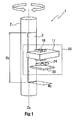
- Fig. 1 is a perspective view illustrating an entire structure of a rotational angle detecting device 1 according to a first embodiment of the present invention.
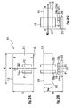
- Figs. 2A to 2C are diagrams illustrating an angle sensor unit 10, wherein Fig. 2A is a plan view thereof, Fig. 2B is a front view thereof and Fig. 2C is a side view thereof.
- the rotational angle detecting device 1 is structured so that the angle sensor unit 10 is arranged to face a shaft 2 rotating as a detected object.
- the angle sensor unit 10 is structured so that a pair of first yokes 18 (18a, 18b) are attached on a permanent magnet 11 and a second yoke 20 is disposed in parallel with the permanent magnet 11 to face the first yokes 18 with a predetermined space therefrom.
- the permanent magnet 11 is formed of a magnetic material of rare-earth isotropic neodymium bond by ejection molding, and is a cuboid having a length L, a width W and a height Hm.
- the left end thereof acts as a south pole (S pole) and the right end thereof acts as a north pole (N pole).
- a straight line passing a center of each of magnetic pole faces 12, 13 of the S pole and the N pole is defined as a reference line K of the permanent magnet 11.
- the pair of the yokes 18 each are composed of a sintered material formed of pure iron powder, and are formed as a magnetic body in a flat plate shape.
- the respective first yokes 18a,18b have flat plate faces that are positioned to be perpendicular to the magnetic pole faces 12, 13 of the S pole and the N pole of the permanent magnet 11, that is, in parallel with the reference line K.
- the first yokes 18a and 18b are positioned to be closer to the S pole of the permanent magnet 11, line-symmetric with respect to the reference line K, and in a distance equal from the magnetic pole face 12 of the S pole.
- each of the first yokes 18a, 18b extends from at least a lower face 15 of permanent magnet 11 and projects to the second yoke 20-side.
- a distance between the first yokes 18a, 18b is from 2 to 4mm and a projecting amount thereof to the second yoke 20-side is from 1 to 2mm.
- first yokes 18 are inserted at ejection molding of the permanent magnet 11 to be united to and held in the permanent magnet 11, and penetrate the permanent magnet 11 and project also from an upper face 14 at the opposite side to the second yoke 20, which act as gripping parts at the inserting.
- the second yoke 20 is a magnetic body made up of a press iron plate, and a plate face thereof has an area that is large enough for entirely facing the respective lower end faces 19 of the first yokes 18a, 18b. Particularly the second yoke 20 extends, as illustrated in Fig. 2C , from a region facing the lower end face 19 of the first yoke 18 to the S pole side in the magnetization direction MD of the permanent magnet 11, thus arranging a front end face 21 thereof to be flush with a magnetic pole face 12 of the S pole, that is, to conform with extension of the magnetic pole face 12.
- Detection points P (P1, P2) of magnetism are set in a space between the first yokes 18a, 18b and the second yoke 20, and hall ICs 24 (24a, 24b) are arranged to conform magnetic sensitive parts thereof with the detection points P.
- the two hall ICs 24a, 24b are arranged to correspond to the detection points P1, P2 respectively, but instead of the two hall ICs, a single hall IC may be arranged if it is equipped with two magnetic sensitive parts corresponding to the detection points P1, P2 in two places.
- the hall ICs 24 perform predetermined calculations based upon the magnetic flux densities in the two directions detected by the magnetic sensitive parts, which will be described later.
- a height from a lower face 22 of the second yoke 20 to the upper face 14 of the permanent magnet 11 is called a detection face height Hs of the angle sensor unit 10.
- the permanent magnet 11, the first yokes 18, the second yoke 20 and the hall ICs 24, which are described above, are accommodated in a case (unillustrated), and therefore the angle sensor unit 10 is in the form of a one-piece independent product and easy to be handled.
- the case can be of a sealing type that may be sealed by a sealing resin or the like, and thereby highly accurate positional relations between the respective components can be stably maintained.
- magnetization of the permanent magnet 11 is preferably performed in a state of holding the first yokes 18, further preferably in a state of being assembled together with the second yoke 20 and the hall ICs 24 to be accommodated in the case. A possibility of the magnetic contamination in each working step of the assembling process is eliminated and the process management becomes easy.
- the shaft 2 of an iron material that is the detected object is provided with a flat face part 3 formed thereon by cutting a part of a column thereof, having a height (flat face part height) Hz and a width (flat face part width) Wz.
- the angle sensor unit 10 is arranged so that the magnetic pole face 12 of the S pole of the permanent magnet 11 and the front end face 21 of the second yoke 20 face the flat face part 3 of the shaft 2.
- the reference line K passing each center of the magnetic pole faces 12, 13 of the permanent magnet 11 is set to traverse a rotational axis Cs of the shaft 2 and be vertical to the rotational axis Cs.
- the flat face part height Hz is set to be greater than an addition value of the detection face height Hs (refer to Fig. 2B ) of the angle sensor unit 10 and an estimated positional shift amount of the shaft 2 in the rotational axis Cs direction.
- a magnetic flux line J by the permanent magnet 11 has a route of passing from the N pole and via the first yoke 18 through the second yoke 20, and further, going back to the S pole via the shaft 2. Then in the detection point P, the hall IC 24 detects the magnetic flux density.
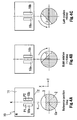
- Figs. 4A to 4C illustrate an arrangement relation between the shaft 2 and the angle sensor unit 10 as viewed from the rotational axis Cs direction of the shaft 2.
- Fig. 4A illustrates a state where the flat face part 3 of the shaft 2 is in parallel with the magnetic pole face 12 of the S pole of the permanent magnet 11, which is set as a reference position of rotation of the shaft 2.
- Fig. 4B illustrates a state where the shaft 2 rotates in a clockwise (right) rotation from the reference position, having a minus value such as -45 degrees.
- Fig.4C illustrates a state where the shaft 2 rotates in a counterclockwise (left) rotation from the reference position, having a plus value such as +45 degrees.
- a direction extending in parallel with the reference line K of the permanent magnet 11 is defined as X direction
- a direction extending in parallel with the rotational axis Cs of the shaft 2 is defined as Z direction
- a direction perpendicular to these X and Z directions and extending in parallel with the flat face part 3 in the reference position of the shaft 2 is defined as Y direction.
- the hall ICs 24a, 24b of the angle sensor unit 10 detect magnetic flux densities in the two directions of the Z direction and Y direction in the detection points P1, P2 corresponding thereto.
- the route of the magnetic flux line J illustrated in Fig. 3 mentioned above is divided into two lines of a route passing the first yoke 18a and a route passing the first yoke 18b since the first yokes 18a and 18b are arranged to be spaced from each other as illustrated in Fig. 2A .Between the two routes, a distance (X direction) between each of the first yokes 18a, 18b and the flat face part 3 changes with rotation of the shaft 2.
- a distance between the first yoke 18a and the flat face part 3 is equal to a distance between the first yoke 18b and the flat face part 3, but when the shaft 2 rotates in a clockwise rotation (direction of -45 degrees) from the reference position, the distance between the first yoke 18a and the flat face part 3 becomes shorter, and on the other hand, the distance between the first yoke 18b and the flat face part 3 becomes longer.
- the change in distance between each of the first yokes 18a, 18b and the flat face part 3 causes a difference in change of the magnetic flux density in the Z direction and the magnetic flux density in the Y direction between the detection points P1, P2 as well.
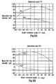
- Figs. 5A and 5B are graphs each indicating a change in magnetic flux density detected at the time of rotating the shaft 2, wherein Fig. 5A indicates the detection result in the detection point P1, and Fig. 5B indicates the detection result in the detection point P2.
- the angle sensor unit 10 used for measurement is structured in such a way that, to the shaft 2 having a diameter of 11 mm in an assumed rotation angle range of approximately 90 degrees, the permanent magnet 11 is sized to have a height (Hm) of 5mm of each of the magnetic pole faces 12, 13, a width (W) of 20mm and a length (L) of 13mm, the first yokes 18a, 18b each have a length of 6mm, a height of 8mm, a plate thickness of 1.4mm and a projecting amount of 1.5mm to each of the second yoke 20-side and the opposite side, a distance between the first yokes 18a, 18b having the reference line K therebetween is set to 2.5mm and the second yoke 20 has a length of 7.5mm, a width of 10mm and a plate thickness of 1 mm.
- the hall ICs 24 are made of ams AG-made AS5403, equipped with two magnetic sensitive parts.
- the shaft 2 having a diameter of 11 m is provided with the flat face part 3 formed thereon, having a flat face part width (Wz) of 10.25mm and a flat face part height (Hz) of 30mm.
- Wz flat face part width
- Hz flat face part height
- Bz1 indicates the magnetic flux density in the Z direction in the detection point P1 and By1 indicates the magnetic flux density in the Y direction in the detection point P1.
- Bz2 indicates the magnetic flux density in the Z direction in the detection point P2 and By2 indicates the magnetic flux density in the Y direction in the detection point P2.
- the hall ICs 24 obtain a calculation angle ⁇ c according to the following formula based upon the difference ⁇ Bz in magnetic flux density in the Z direction and the difference ⁇ By in magnetic flux density in the Y direction.
- ⁇ c Arctan ⁇ Bz / ⁇ By
- Fig. 7 is a graph indicating the calculation angle ⁇ c.
- the calculation angle ⁇ c is indicated approximately in a straight line in an entire region from -45 degrees to +45 degrees of the rotational angle of the shaft 2, and it is found out that the calculation angle ⁇ c has a proportional relation to the rotational angle of the shaft 2.
- an actual rotational angle ⁇ t of the shaft 2 can be obtained by multiplying a calculation angle ⁇ c output as a detection signal by the hall IC 24 by a predetermined coefficient, finding the calculation angle ⁇ c is substantially equivalent to finding the rotational angle of the shaft 2.
- the found calculation angle ⁇ c is converted into a predetermined electrical signal to be output.
- the flat face part height Hz of the shaft 2 is set to be greater than an addition value of the detection face height Hs and the positional shift amount of the shaft 2 in the direction of the rotational axis Cs, the calculation angle ⁇ c is not subjected to any influence of the positional shift in the Z direction.
- the present embodiment since the present embodiment has no variation in detection characteristics by the positional shift of the shaft or controls the variation to be small, it has so-called high robustness.
- the first yokes 18a, 18b are arranged in line symmetry with respect to the reference line K (X direction) of the permanent magnet 11 passing the rotational axis Cs of the shaft 2, a variation amount of the magnetic flux density by the magnetic noises in the X direction is equal between the points P1, P2, and the calculation angle ⁇ c based upon the difference in magnetic flux density is not influenced. This is true of magnetic noises in the Z direction, and the calculation angle ⁇ c has an extremely large resistance to the magnetic noises in the two directions.
- the shaft 2 corresponds to a detected object in the present invention
- the magnetic pole face 12 of the S pole in the permanent magnet 11 corresponds to a magnetic pole face of one end in the magnetization direction.
- the lower face 15 of the permanent magnet 11 corresponds to a face from which the first yoke projects, and the lower end face 19 of the first yoke 18 corresponds to a projecting lower end.
- the hall IC 24 corresponds to a magnetic detection element
- the magnetic flux densities Bz1, Bz2 in the Z direction correspond to magnetic flux densities in the direction in parallel with the rotational axis
- the magnetic flux densities By1, By2 in the Y direction correspond to magnetic flux densities in the direction perpendicular to the rotational axis and the reference line.
- the first embodiment is configured as described above, and is provided with the rotational angle detecting device comprising:
- the rotation transmitting mechanism is not necessary because of detecting the rotation of the shaft 2 based upon a change in distance between the flat face part 3 and the first yokes 18.
- the permanent magnet 11, the first yokes 18, the second yoke 20 and the hall ICs 24 can be formed as the one-piece angle sensor unit 10. Therefore the complicated holding structure of the rotational member and the air-tight accommodation space are not required therein.
- the angle sensor unit can be manufactured in low costs and miniaturized as a whole, and a degree of freedom to the application object and the installation portion is large and the mechanical errors are eliminated, thus making it possible to obtain high detection precision.
- the difference in magnetic flux density in the Z direction and the difference in magnetic flux density in the Y direction between the detection points P1, P2 are calculated, and the rotational angle of the shaft 2 is found based upon both of the differences. Therefore the variation in detection characteristics by the positional shift of the rotational axis in the shaft 2 is suppressed, and the variation in detection characteristics is suppressed also to the external magnetic noises, thus creating high robustness. (Effect corresponding to claim 2)
- the first yokes 18a, 18b are arranged in parallel with each other having the reference line K therebetween, it is not subjected to the influence of the magnetic noises from this point as well. (Effect corresponding to claim 4)
- the permanent magnet 11 is formed by ejection molding, and the first yokes 18 are inserted at ejection molding to be held by the permanent magnet 11. Therefore, as compared to a case of separately assembling the first yokes 18 to the molded permanent magnet, an accurate assembling structure is not required, there is no possibility of generation of clearances and the manufacture is easy. (Effect corresponding to claim 7)
- the permanent magnet 11 is magnetized in a state of holding the first yokes 18 or after being assembled to the angle sensor unit 10, which makes it possible to avoid the variation in magnetic characteristics or the magnetic contamination in the middle of the assembling process. (Effect corresponding to claim 8)
- Fig. 8 illustrates a modification of an arrangement of first yokes in the angle sensor unit 10.
- First yokes 18a, 18b are arranged in line symmetry with respect to the reference line K of the permanent magnet 11 as similar to the first embodiment, but are inclined so that a separate distance from each other is larger in a side closer to the magnetic pole face 12 facing the flat face part 3 and smaller in a side farther therefrom, thus being formed in a wedge shape as viewed from above (Z direction).
- the other configuration is similar to that of the first embodiment.
- the detection accuracy of the angle sensor unit is the more susceptible to magnetic noises, but by inclining the first yokes 18 in a crossing angle of 30 degrees (each having the inclination angle of 15 degrees to the reference line K), for example, the magnetic flux densities in the Z direction and in the Y direction of the shaft 2 vary largely, which makes the detection sensitivity higher. Therefore the inclination angle can be set in consideration of the balance of both. (Effect corresponding to claim 5)
- the angle sensor unit 10 has the same structure as that of the first embodiment, but differs in the processing of magnetic flux densities detected in the detection points P (P1, P2) from the first embodiment.
- the calculation on the difference in magnetic flux density is used, but in a case where the magnetic flux density applied to the detection point P is small, a difference in magnetic flux density also becomes small, which possibly makes a value of the calculation angle ⁇ c small.
- the detection sensitivity is made better, and in a case where the magnetic flux density applied to the detection point P is small and in a case where the difference in magnetic flux density is small, a large value of the calculation angle ⁇ c can be obtained. Therefore the rotational angle of the shaft 2 having the high resolution can be obtained. (Effect corresponding to claim 3)
- the first yokes 18 are inserted at the same time with the ejection molding of the permanent magnet 11 to be united therewith, but in a case of assembling the first yokes 18 after the formation of the permanent magnet 11, holes each matched with a shape and a size of the first yoke 18 are first formed in the permanent magnet 11, and then the first yokes 18 are inserted in the holes.
- the magnetic pole face 12 of the S pole in the permanent magnet 11 is arranged to face the flat face part 3 of the shaft 2, but regardless of the polarity, the magnetic pole face 13 of the N pole may be arranged to face the flat face part 3 to reverse the direction of the flow of the magnetic flux line J. In this case, it is preferable to extend an end edge of the second yoke 20 facing the flat face part 3 to be flush with the magnetic pole face 13 of the N pole.
Landscapes
- Physics & Mathematics (AREA)
- General Physics & Mathematics (AREA)
- Transmission And Conversion Of Sensor Element Output (AREA)
Priority Applications (1)
| Application Number | Priority Date | Filing Date | Title |
|---|---|---|---|
| EP16194928.4A EP3312564B1 (fr) | 2016-10-20 | 2016-10-20 | Dispositif de détection d'angle de rotation et détecteur d'angle utilisé en son sein |
Applications Claiming Priority (1)
| Application Number | Priority Date | Filing Date | Title |
|---|---|---|---|
| EP16194928.4A EP3312564B1 (fr) | 2016-10-20 | 2016-10-20 | Dispositif de détection d'angle de rotation et détecteur d'angle utilisé en son sein |
Publications (2)
| Publication Number | Publication Date |
|---|---|
| EP3312564A1 true EP3312564A1 (fr) | 2018-04-25 |
| EP3312564B1 EP3312564B1 (fr) | 2020-04-01 |
Family
ID=57199909
Family Applications (1)
| Application Number | Title | Priority Date | Filing Date |
|---|---|---|---|
| EP16194928.4A Active EP3312564B1 (fr) | 2016-10-20 | 2016-10-20 | Dispositif de détection d'angle de rotation et détecteur d'angle utilisé en son sein |
Country Status (1)
| Country | Link |
|---|---|
| EP (1) | EP3312564B1 (fr) |
Cited By (1)
| Publication number | Priority date | Publication date | Assignee | Title |
|---|---|---|---|---|
| EP3667248A1 (fr) * | 2018-12-13 | 2020-06-17 | Analog Devices International Unlimited Company | Systèmes et procédés de détermination de position magnétique |
Citations (6)
| Publication number | Priority date | Publication date | Assignee | Title |
|---|---|---|---|---|
| US6275027B1 (en) * | 1998-09-19 | 2001-08-14 | Unisia Jecs Corporation | Rotation angle sensor |
| US20040189288A1 (en) * | 2003-03-31 | 2004-09-30 | Denso Corporation | Rotation angle detecting device |
| JP5131537B2 (ja) | 2007-04-25 | 2013-01-30 | アイシン精機株式会社 | 角度検出装置 |
| US20130033259A1 (en) * | 2011-08-04 | 2013-02-07 | Denso Corporation | Position detector |
| EP2755306A2 (fr) * | 2013-01-15 | 2014-07-16 | Kabushiki Kaisha Yaskawa Denki | Capteur de rotation d'unité de moteur |
| US20140225595A1 (en) * | 2011-06-30 | 2014-08-14 | Valeo Japan Co., Ltd. | Proximity sensor |
-
2016
- 2016-10-20 EP EP16194928.4A patent/EP3312564B1/fr active Active
Patent Citations (6)
| Publication number | Priority date | Publication date | Assignee | Title |
|---|---|---|---|---|
| US6275027B1 (en) * | 1998-09-19 | 2001-08-14 | Unisia Jecs Corporation | Rotation angle sensor |
| US20040189288A1 (en) * | 2003-03-31 | 2004-09-30 | Denso Corporation | Rotation angle detecting device |
| JP5131537B2 (ja) | 2007-04-25 | 2013-01-30 | アイシン精機株式会社 | 角度検出装置 |
| US20140225595A1 (en) * | 2011-06-30 | 2014-08-14 | Valeo Japan Co., Ltd. | Proximity sensor |
| US20130033259A1 (en) * | 2011-08-04 | 2013-02-07 | Denso Corporation | Position detector |
| EP2755306A2 (fr) * | 2013-01-15 | 2014-07-16 | Kabushiki Kaisha Yaskawa Denki | Capteur de rotation d'unité de moteur |
Cited By (4)
| Publication number | Priority date | Publication date | Assignee | Title |
|---|---|---|---|---|
| EP3667248A1 (fr) * | 2018-12-13 | 2020-06-17 | Analog Devices International Unlimited Company | Systèmes et procédés de détermination de position magnétique |
| CN111322937A (zh) * | 2018-12-13 | 2020-06-23 | 亚德诺半导体国际无限责任公司 | 磁性位置测定系统和方法 |
| CN111322937B (zh) * | 2018-12-13 | 2022-04-19 | 亚德诺半导体国际无限责任公司 | 磁性位置测定系统和方法 |
| US11573072B2 (en) | 2018-12-13 | 2023-02-07 | Analog Devices International Unlimited Company | Magnetic position determination systems and methods |
Also Published As
| Publication number | Publication date |
|---|---|
| EP3312564B1 (fr) | 2020-04-01 |
Similar Documents
| Publication | Publication Date | Title |
|---|---|---|
| US10060759B2 (en) | Rotational angle detecting device and angle sensor unit used therein | |
| EP2728302B1 (fr) | Capteur de proximité | |
| EP2525193B1 (fr) | Capteur de proximité magnétique | |
| US6586929B1 (en) | Magnetic position sensor having shaped pole pieces for improved output linearity | |
| EP1553387A1 (fr) | Détecteur de position linéaire magnétique | |
| EP3816599A1 (fr) | Module de détection magnétique, dispositif de détection, ensemble boîtier et procédé de production de module de détection magnétique | |
| US20130154618A1 (en) | Integrated magnetic field sensor and method for a measurement of the position of a ferromagnetic workpiece with an integrated magnetic field sensor | |
| EP3368863B1 (fr) | Méthodes et appareil pour séectionner le déphasage dans la détection d'un aimant annulaire | |
| US6798195B2 (en) | Magnetic position sensor having shaped pole pieces at least partially formed of a non-magnetic material for producing a magnetic field having varying magnetic flux density along an axis | |
| JP2005227095A (ja) | 磁気変量センサ | |
| EP1365208A1 (fr) | Capteur de deplacement | |
| US20210231699A1 (en) | Protective sleeve for a revolution rate sensor | |
| US12007256B2 (en) | Magnet holder and stroke sensor with the magnet holder | |
| EP3312564B1 (fr) | Dispositif de détection d'angle de rotation et détecteur d'angle utilisé en son sein | |
| EP4034842B1 (fr) | Agencement de mesure de déplacement doté d'un capteur à effet hall et d'un aimant | |
| EP4109064B1 (fr) | Module de détection magnétique, dispositif de détection, ensemble boîtier et procédé de production d'un module de détection magnétique | |
| US11287030B2 (en) | Shift device | |
| WO2016093059A1 (fr) | Capteur de courant | |
| US11181394B2 (en) | Distance measuring device | |
| JP3233129B2 (ja) | 磁気検出装置 | |
| JP7240595B2 (ja) | 移動体検出装置、及び移動体検出装置の製造方法 | |
| JPH06174490A (ja) | 磁気検出装置 | |
| WO2025120986A1 (fr) | Capteur de courant | |
| JPH11337370A (ja) | 磁気検出装置 | |
| CN104169686A (zh) | 包括磁体和霍尔效应探针的传感器 |
Legal Events
| Date | Code | Title | Description |
|---|---|---|---|
| PUAI | Public reference made under article 153(3) epc to a published international application that has entered the european phase |
Free format text: ORIGINAL CODE: 0009012 |
|
| STAA | Information on the status of an ep patent application or granted ep patent |
Free format text: STATUS: THE APPLICATION HAS BEEN PUBLISHED |
|
| AK | Designated contracting states |
Kind code of ref document: A1 Designated state(s): AL AT BE BG CH CY CZ DE DK EE ES FI FR GB GR HR HU IE IS IT LI LT LU LV MC MK MT NL NO PL PT RO RS SE SI SK SM TR |
|
| AX | Request for extension of the european patent |
Extension state: BA ME |
|
| STAA | Information on the status of an ep patent application or granted ep patent |
Free format text: STATUS: REQUEST FOR EXAMINATION WAS MADE |
|
| 17P | Request for examination filed |
Effective date: 20181023 |
|
| RBV | Designated contracting states (corrected) |
Designated state(s): AL AT BE BG CH CY CZ DE DK EE ES FI FR GB GR HR HU IE IS IT LI LT LU LV MC MK MT NL NO PL PT RO RS SE SI SK SM TR |
|
| GRAP | Despatch of communication of intention to grant a patent |
Free format text: ORIGINAL CODE: EPIDOSNIGR1 |
|
| STAA | Information on the status of an ep patent application or granted ep patent |
Free format text: STATUS: GRANT OF PATENT IS INTENDED |
|
| INTG | Intention to grant announced |
Effective date: 20191009 |
|
| RIN1 | Information on inventor provided before grant (corrected) |
Inventor name: SATO, SHUNICHI |
|
| GRAS | Grant fee paid |
Free format text: ORIGINAL CODE: EPIDOSNIGR3 |
|
| GRAA | (expected) grant |
Free format text: ORIGINAL CODE: 0009210 |
|
| STAA | Information on the status of an ep patent application or granted ep patent |
Free format text: STATUS: THE PATENT HAS BEEN GRANTED |
|
| AK | Designated contracting states |
Kind code of ref document: B1 Designated state(s): AL AT BE BG CH CY CZ DE DK EE ES FI FR GB GR HR HU IE IS IT LI LT LU LV MC MK MT NL NO PL PT RO RS SE SI SK SM TR |
|
| REG | Reference to a national code |
Ref country code: GB Ref legal event code: FG4D |
|
| REG | Reference to a national code |
Ref country code: CH Ref legal event code: EP Ref country code: AT Ref legal event code: REF Ref document number: 1251937 Country of ref document: AT Kind code of ref document: T Effective date: 20200415 |
|
| REG | Reference to a national code |
Ref country code: DE Ref legal event code: R096 Ref document number: 602016032916 Country of ref document: DE |
|
| REG | Reference to a national code |
Ref country code: IE Ref legal event code: FG4D |
|
| PG25 | Lapsed in a contracting state [announced via postgrant information from national office to epo] |
Ref country code: BG Free format text: LAPSE BECAUSE OF FAILURE TO SUBMIT A TRANSLATION OF THE DESCRIPTION OR TO PAY THE FEE WITHIN THE PRESCRIBED TIME-LIMIT Effective date: 20200701 |
|
| REG | Reference to a national code |
Ref country code: NL Ref legal event code: MP Effective date: 20200401 |
|
| REG | Reference to a national code |
Ref country code: LT Ref legal event code: MG4D |
|
| PG25 | Lapsed in a contracting state [announced via postgrant information from national office to epo] |
Ref country code: NO Free format text: LAPSE BECAUSE OF FAILURE TO SUBMIT A TRANSLATION OF THE DESCRIPTION OR TO PAY THE FEE WITHIN THE PRESCRIBED TIME-LIMIT Effective date: 20200701 Ref country code: FI Free format text: LAPSE BECAUSE OF FAILURE TO SUBMIT A TRANSLATION OF THE DESCRIPTION OR TO PAY THE FEE WITHIN THE PRESCRIBED TIME-LIMIT Effective date: 20200401 Ref country code: GR Free format text: LAPSE BECAUSE OF FAILURE TO SUBMIT A TRANSLATION OF THE DESCRIPTION OR TO PAY THE FEE WITHIN THE PRESCRIBED TIME-LIMIT Effective date: 20200702 Ref country code: PT Free format text: LAPSE BECAUSE OF FAILURE TO SUBMIT A TRANSLATION OF THE DESCRIPTION OR TO PAY THE FEE WITHIN THE PRESCRIBED TIME-LIMIT Effective date: 20200817 Ref country code: NL Free format text: LAPSE BECAUSE OF FAILURE TO SUBMIT A TRANSLATION OF THE DESCRIPTION OR TO PAY THE FEE WITHIN THE PRESCRIBED TIME-LIMIT Effective date: 20200401 Ref country code: IS Free format text: LAPSE BECAUSE OF FAILURE TO SUBMIT A TRANSLATION OF THE DESCRIPTION OR TO PAY THE FEE WITHIN THE PRESCRIBED TIME-LIMIT Effective date: 20200801 Ref country code: CZ Free format text: LAPSE BECAUSE OF FAILURE TO SUBMIT A TRANSLATION OF THE DESCRIPTION OR TO PAY THE FEE WITHIN THE PRESCRIBED TIME-LIMIT Effective date: 20200401 Ref country code: LT Free format text: LAPSE BECAUSE OF FAILURE TO SUBMIT A TRANSLATION OF THE DESCRIPTION OR TO PAY THE FEE WITHIN THE PRESCRIBED TIME-LIMIT Effective date: 20200401 Ref country code: SE Free format text: LAPSE BECAUSE OF FAILURE TO SUBMIT A TRANSLATION OF THE DESCRIPTION OR TO PAY THE FEE WITHIN THE PRESCRIBED TIME-LIMIT Effective date: 20200401 |
|
| REG | Reference to a national code |
Ref country code: AT Ref legal event code: MK05 Ref document number: 1251937 Country of ref document: AT Kind code of ref document: T Effective date: 20200401 |
|
| PG25 | Lapsed in a contracting state [announced via postgrant information from national office to epo] |
Ref country code: HR Free format text: LAPSE BECAUSE OF FAILURE TO SUBMIT A TRANSLATION OF THE DESCRIPTION OR TO PAY THE FEE WITHIN THE PRESCRIBED TIME-LIMIT Effective date: 20200401 Ref country code: LV Free format text: LAPSE BECAUSE OF FAILURE TO SUBMIT A TRANSLATION OF THE DESCRIPTION OR TO PAY THE FEE WITHIN THE PRESCRIBED TIME-LIMIT Effective date: 20200401 Ref country code: RS Free format text: LAPSE BECAUSE OF FAILURE TO SUBMIT A TRANSLATION OF THE DESCRIPTION OR TO PAY THE FEE WITHIN THE PRESCRIBED TIME-LIMIT Effective date: 20200401 |
|
| PG25 | Lapsed in a contracting state [announced via postgrant information from national office to epo] |
Ref country code: AL Free format text: LAPSE BECAUSE OF FAILURE TO SUBMIT A TRANSLATION OF THE DESCRIPTION OR TO PAY THE FEE WITHIN THE PRESCRIBED TIME-LIMIT Effective date: 20200401 |
|
| REG | Reference to a national code |
Ref country code: DE Ref legal event code: R097 Ref document number: 602016032916 Country of ref document: DE |
|
| PG25 | Lapsed in a contracting state [announced via postgrant information from national office to epo] |
Ref country code: ES Free format text: LAPSE BECAUSE OF FAILURE TO SUBMIT A TRANSLATION OF THE DESCRIPTION OR TO PAY THE FEE WITHIN THE PRESCRIBED TIME-LIMIT Effective date: 20200401 Ref country code: RO Free format text: LAPSE BECAUSE OF FAILURE TO SUBMIT A TRANSLATION OF THE DESCRIPTION OR TO PAY THE FEE WITHIN THE PRESCRIBED TIME-LIMIT Effective date: 20200401 Ref country code: AT Free format text: LAPSE BECAUSE OF FAILURE TO SUBMIT A TRANSLATION OF THE DESCRIPTION OR TO PAY THE FEE WITHIN THE PRESCRIBED TIME-LIMIT Effective date: 20200401 Ref country code: DK Free format text: LAPSE BECAUSE OF FAILURE TO SUBMIT A TRANSLATION OF THE DESCRIPTION OR TO PAY THE FEE WITHIN THE PRESCRIBED TIME-LIMIT Effective date: 20200401 Ref country code: SM Free format text: LAPSE BECAUSE OF FAILURE TO SUBMIT A TRANSLATION OF THE DESCRIPTION OR TO PAY THE FEE WITHIN THE PRESCRIBED TIME-LIMIT Effective date: 20200401 Ref country code: IT Free format text: LAPSE BECAUSE OF FAILURE TO SUBMIT A TRANSLATION OF THE DESCRIPTION OR TO PAY THE FEE WITHIN THE PRESCRIBED TIME-LIMIT Effective date: 20200401 Ref country code: EE Free format text: LAPSE BECAUSE OF FAILURE TO SUBMIT A TRANSLATION OF THE DESCRIPTION OR TO PAY THE FEE WITHIN THE PRESCRIBED TIME-LIMIT Effective date: 20200401 |
|
| PLBE | No opposition filed within time limit |
Free format text: ORIGINAL CODE: 0009261 |
|
| STAA | Information on the status of an ep patent application or granted ep patent |
Free format text: STATUS: NO OPPOSITION FILED WITHIN TIME LIMIT |
|
| PG25 | Lapsed in a contracting state [announced via postgrant information from national office to epo] |
Ref country code: PL Free format text: LAPSE BECAUSE OF FAILURE TO SUBMIT A TRANSLATION OF THE DESCRIPTION OR TO PAY THE FEE WITHIN THE PRESCRIBED TIME-LIMIT Effective date: 20200401 Ref country code: SK Free format text: LAPSE BECAUSE OF FAILURE TO SUBMIT A TRANSLATION OF THE DESCRIPTION OR TO PAY THE FEE WITHIN THE PRESCRIBED TIME-LIMIT Effective date: 20200401 |
|
| 26N | No opposition filed |
Effective date: 20210112 |
|
| PG25 | Lapsed in a contracting state [announced via postgrant information from national office to epo] |
Ref country code: SI Free format text: LAPSE BECAUSE OF FAILURE TO SUBMIT A TRANSLATION OF THE DESCRIPTION OR TO PAY THE FEE WITHIN THE PRESCRIBED TIME-LIMIT Effective date: 20200401 |
|
| REG | Reference to a national code |
Ref country code: CH Ref legal event code: PL |
|
| PG25 | Lapsed in a contracting state [announced via postgrant information from national office to epo] |
Ref country code: MC Free format text: LAPSE BECAUSE OF FAILURE TO SUBMIT A TRANSLATION OF THE DESCRIPTION OR TO PAY THE FEE WITHIN THE PRESCRIBED TIME-LIMIT Effective date: 20200401 Ref country code: LU Free format text: LAPSE BECAUSE OF NON-PAYMENT OF DUE FEES Effective date: 20201020 |
|
| REG | Reference to a national code |
Ref country code: BE Ref legal event code: MM Effective date: 20201031 |
|
| PG25 | Lapsed in a contracting state [announced via postgrant information from national office to epo] |
Ref country code: LI Free format text: LAPSE BECAUSE OF NON-PAYMENT OF DUE FEES Effective date: 20201031 Ref country code: CH Free format text: LAPSE BECAUSE OF NON-PAYMENT OF DUE FEES Effective date: 20201031 Ref country code: BE Free format text: LAPSE BECAUSE OF NON-PAYMENT OF DUE FEES Effective date: 20201031 |
|
| PG25 | Lapsed in a contracting state [announced via postgrant information from national office to epo] |
Ref country code: IE Free format text: LAPSE BECAUSE OF NON-PAYMENT OF DUE FEES Effective date: 20201020 |
|
| PGFP | Annual fee paid to national office [announced via postgrant information from national office to epo] |
Ref country code: GB Payment date: 20211123 Year of fee payment: 6 Ref country code: DE Payment date: 20211105 Year of fee payment: 6 |
|
| PGFP | Annual fee paid to national office [announced via postgrant information from national office to epo] |
Ref country code: FR Payment date: 20211025 Year of fee payment: 6 |
|
| PG25 | Lapsed in a contracting state [announced via postgrant information from national office to epo] |
Ref country code: TR Free format text: LAPSE BECAUSE OF FAILURE TO SUBMIT A TRANSLATION OF THE DESCRIPTION OR TO PAY THE FEE WITHIN THE PRESCRIBED TIME-LIMIT Effective date: 20200401 Ref country code: MT Free format text: LAPSE BECAUSE OF FAILURE TO SUBMIT A TRANSLATION OF THE DESCRIPTION OR TO PAY THE FEE WITHIN THE PRESCRIBED TIME-LIMIT Effective date: 20200401 Ref country code: CY Free format text: LAPSE BECAUSE OF FAILURE TO SUBMIT A TRANSLATION OF THE DESCRIPTION OR TO PAY THE FEE WITHIN THE PRESCRIBED TIME-LIMIT Effective date: 20200401 |
|
| PG25 | Lapsed in a contracting state [announced via postgrant information from national office to epo] |
Ref country code: MK Free format text: LAPSE BECAUSE OF FAILURE TO SUBMIT A TRANSLATION OF THE DESCRIPTION OR TO PAY THE FEE WITHIN THE PRESCRIBED TIME-LIMIT Effective date: 20200401 |
|
| REG | Reference to a national code |
Ref country code: DE Ref legal event code: R119 Ref document number: 602016032916 Country of ref document: DE |
|
| GBPC | Gb: european patent ceased through non-payment of renewal fee |
Effective date: 20221020 |
|
| P01 | Opt-out of the competence of the unified patent court (upc) registered |
Effective date: 20230528 |
|
| PG25 | Lapsed in a contracting state [announced via postgrant information from national office to epo] |
Ref country code: FR Free format text: LAPSE BECAUSE OF NON-PAYMENT OF DUE FEES Effective date: 20221031 Ref country code: DE Free format text: LAPSE BECAUSE OF NON-PAYMENT OF DUE FEES Effective date: 20230503 |
|
| PG25 | Lapsed in a contracting state [announced via postgrant information from national office to epo] |
Ref country code: GB Free format text: LAPSE BECAUSE OF NON-PAYMENT OF DUE FEES Effective date: 20221020 |