EP3667248A1 - Systèmes et procédés de détermination de position magnétique - Google Patents
Systèmes et procédés de détermination de position magnétique Download PDFInfo
- Publication number
- EP3667248A1 EP3667248A1 EP19213311.4A EP19213311A EP3667248A1 EP 3667248 A1 EP3667248 A1 EP 3667248A1 EP 19213311 A EP19213311 A EP 19213311A EP 3667248 A1 EP3667248 A1 EP 3667248A1
- Authority
- EP
- European Patent Office
- Prior art keywords
- sensor
- magnetic field
- field
- magnet
- sensors
- Prior art date
- Legal status (The legal status is an assumption and is not a legal conclusion. Google has not performed a legal analysis and makes no representation as to the accuracy of the status listed.)
- Granted
Links
Images


Classifications
-
- G—PHYSICS
- G01—MEASURING; TESTING
- G01D—MEASURING NOT SPECIALLY ADAPTED FOR A SPECIFIC VARIABLE; ARRANGEMENTS FOR MEASURING TWO OR MORE VARIABLES NOT COVERED IN A SINGLE OTHER SUBCLASS; TARIFF METERING APPARATUS; MEASURING OR TESTING NOT OTHERWISE PROVIDED FOR
- G01D5/00—Mechanical means for transferring the output of a sensing member; Means for converting the output of a sensing member to another variable where the form or nature of the sensing member does not constrain the means for converting; Transducers not specially adapted for a specific variable
- G01D5/12—Mechanical means for transferring the output of a sensing member; Means for converting the output of a sensing member to another variable where the form or nature of the sensing member does not constrain the means for converting; Transducers not specially adapted for a specific variable using electric or magnetic means
- G01D5/14—Mechanical means for transferring the output of a sensing member; Means for converting the output of a sensing member to another variable where the form or nature of the sensing member does not constrain the means for converting; Transducers not specially adapted for a specific variable using electric or magnetic means influencing the magnitude of a current or voltage
- G01D5/142—Mechanical means for transferring the output of a sensing member; Means for converting the output of a sensing member to another variable where the form or nature of the sensing member does not constrain the means for converting; Transducers not specially adapted for a specific variable using electric or magnetic means influencing the magnitude of a current or voltage using Hall-effect devices
- G01D5/145—Mechanical means for transferring the output of a sensing member; Means for converting the output of a sensing member to another variable where the form or nature of the sensing member does not constrain the means for converting; Transducers not specially adapted for a specific variable using electric or magnetic means influencing the magnitude of a current or voltage using Hall-effect devices influenced by the relative movement between the Hall device and magnetic fields
-
- G—PHYSICS
- G01—MEASURING; TESTING
- G01B—MEASURING LENGTH, THICKNESS OR SIMILAR LINEAR DIMENSIONS; MEASURING ANGLES; MEASURING AREAS; MEASURING IRREGULARITIES OF SURFACES OR CONTOURS
- G01B7/00—Measuring arrangements characterised by the use of electric or magnetic techniques
- G01B7/003—Measuring arrangements characterised by the use of electric or magnetic techniques for measuring position, not involving coordinate determination
-
- G—PHYSICS
- G01—MEASURING; TESTING
- G01B—MEASURING LENGTH, THICKNESS OR SIMILAR LINEAR DIMENSIONS; MEASURING ANGLES; MEASURING AREAS; MEASURING IRREGULARITIES OF SURFACES OR CONTOURS
- G01B7/00—Measuring arrangements characterised by the use of electric or magnetic techniques
- G01B7/30—Measuring arrangements characterised by the use of electric or magnetic techniques for measuring angles or tapers; for testing the alignment of axes
-
- G—PHYSICS
- G01—MEASURING; TESTING
- G01R—MEASURING ELECTRIC VARIABLES; MEASURING MAGNETIC VARIABLES
- G01R33/00—Arrangements or instruments for measuring magnetic variables
- G01R33/0094—Sensor arrays
-
- G—PHYSICS
- G01—MEASURING; TESTING
- G01R—MEASURING ELECTRIC VARIABLES; MEASURING MAGNETIC VARIABLES
- G01R33/00—Arrangements or instruments for measuring magnetic variables
- G01R33/02—Measuring direction or magnitude of magnetic fields or magnetic flux
- G01R33/04—Measuring direction or magnitude of magnetic fields or magnetic flux using the flux-gate principle
-
- G—PHYSICS
- G01—MEASURING; TESTING
- G01R—MEASURING ELECTRIC VARIABLES; MEASURING MAGNETIC VARIABLES
- G01R33/00—Arrangements or instruments for measuring magnetic variables
- G01R33/02—Measuring direction or magnitude of magnetic fields or magnetic flux
- G01R33/06—Measuring direction or magnitude of magnetic fields or magnetic flux using galvano-magnetic devices
- G01R33/07—Hall effect devices
-
- G—PHYSICS
- G01—MEASURING; TESTING
- G01R—MEASURING ELECTRIC VARIABLES; MEASURING MAGNETIC VARIABLES
- G01R33/00—Arrangements or instruments for measuring magnetic variables
- G01R33/02—Measuring direction or magnitude of magnetic fields or magnetic flux
- G01R33/06—Measuring direction or magnitude of magnetic fields or magnetic flux using galvano-magnetic devices
- G01R33/09—Magnetoresistive devices
Definitions
- the present application relates to magnetic systems and corresponding methods for determining a position of a movable object.
- Some object position tracking systems use a magnet and a single magnetic sensor.
- the magnet is placed on a movable object. Moving the object changes the magnetic field sensed by the single magnetic field sensor. A determination of the object's position is made based on the sensed magnetic field.
- Systems and methods are provided for determining a position of a magnet.
- the systems and methods utilize a first sensor located at a first sensor position and arranged to measure at least two components of a magnetic field produced by the magnet, a second sensor located at a second sensor position and arranged to measure at least two components of the magnetic field produced by the magnet, and processing circuitry operatively connected to the first and second sensors to receive signals derived from signals outputted by the first and second sensors.
- a field angle is calculated from a first differential field of a first field dimension and a second differential field of a second field dimension orthogonal to the first field dimension.
- the first and second differential fields are calculated based on signals outputted by the first and second sensors.
- an object position determination system may include a movable object, a magnet configured to produce a magnetic field, and a plurality of magnetic field sensors configured to detect components of the magnetic field produced by the magnet in first and second directions at first and second locations.
- the magnet or the plurality of magnetic field sensors may be coupled to the movable object.
- the first direction may be orthogonal to the second direction.
- the plurality of magnetic field sensors may include: at the first location, a first sensor configured to detect a component of the magnetic field in the first direction and a second sensor configured to detect a component of the magnetic field in the second direction, and, at the second location, a third sensor configured to detect a component of the magnetic field in the first direction and a fourth sensor configured to detect a component of the magnetic field in the second direction.
- a system for determining a position of a magnet may include a first sensor located at a first sensor position and arranged to measure at least two components of a magnetic field produced by the magnet, a second sensor located at a second sensor position and arranged to measure at least two components of the magnetic field produced by the magnet, and processing circuitry operatively connected to the first and second sensors to receive signals derived from signals outputted by the first and second sensors.
- the processing circuitry may calculate a field angle from a first differential field in a first field dimension and a second differential field in a second field dimension orthogonal to the first field dimension, and may output a signal indicating a position of the magnet based on the calculated field angle.
- the first and second differential fields may be obtained based on the signals outputted by the first and second sensors.
- a method for determining a position of a magnet may include providing a sensor system that may include first and second sensors arranged to measure at least two components of the magnet's magnetic field at first and second sensor positions, respectively; and using a microprocessor operatively connected to the first and second sensors to: receive signals derived from signals outputted by the first and second sensors, calculate a field angle from a first differential field in a first field dimension and a second differential field in a second field dimension orthogonal to the first dimension, and output a position of the magnet based on the field angle calculated from the first and second differential fields.
- the first and second differential fields may be obtained based on the received signals.
- a device where there is a movable part or object it may be desirable to be able determine whether the object is moving properly and predictably along a known path. This determination can be useful to diagnose a potential malfunction of the device, among other possible uses. However, it can be difficult if not impossible to view the object while it moves, because the object may be hidden from view and/or may be too small to be visualized easily.
- Magnets can be used to track an object's location or position.
- a useful feature of magnets is that they can provide homing signals without requiring a power source and also without requiring transmission wires or even a transmitter. More specifically, a magnet can provide a homing signal in the form of a magnetic field.
- the magnetic field has directional characteristics resulting from the presence of north and south poles of the magnet.
- the magnetic field also has an intensity or strength that varies as a function of distance from the magnet's center. That is, the strength of a magnet's magnetic field decreases as the distance from the magnet's center increases.
- the properties of a magnet's magnetic field may be exploited to determine a location or position of the magnet. These properties may also be exploited to track a position of a movable object. By attaching a magnet to the object and measuring the magnetic field of the magnet, the object's position can be determined even if the object cannot be seen.
- a magnet should be, in at least some embodiments, sized so that it would not impede or alter the small object's normal movement.
- One consideration in using a small magnet is that its magnetic field would be small and hard to discern from environmental magnetic fields, commonly referred to as stray fields.
- stray fields produced by common electrical equipment e.g., lights, phones, computers, televisions
- Some aspects of the present technology provide systems and methods that enable a small magnetic field, such as that produced by a small-sized magnet, to be sensed and measured precisely and reproducibly even in the presence of a stray field, thus enabling a position or location of the magnet to be determined precisely and reproducibly.
- the magnetic system may thus be used to determine the position of an object, such as a movable object to which the magnet may be attached.
- an object position determination system may be comprised of a movable object, a magnet configured to produce a magnetic field, and a plurality of magnetic field sensors configured to detect the magnetic field produced by the magnet along first and second directions at first and second locations.
- the magnet or the plurality of magnetic field sensors may be coupled to the movable object.
- the first and second directions may be orthogonal to each other (e.g., x and z; or x and y; or y and z).
- the plurality of magnetic field sensors may include: at the first location, a first sensor that detects the magnetic field along the first direction and a second sensor that detects the magnetic field along the second direction; and, at the second location, a third sensor that detects the magnetic field along the first direction and a fourth sensor that detects the magnetic field along the second direction.
- the magnet may be coupled to the movable object, and the plurality of magnetic field sensors may be fixed in place.
- some or all of the plurality of magnetic field sensors may be magnetoresistive sensors.
- the first and second sensors may be magnetoresistive sensors, or the first and third sensors may be magnetoresistive sensors.
- the system may be further comprised of processing circuitry coupled to the plurality of magnetic field sensors.
- the processing circuitry may be configured to determine differential magnetic field values in the first and second directions based on output signals from the plurality of magnetic field sensors.
- the first sensor, the second sensor, the third sensor, and the fourth sensor may be co-linear along an axis extending in the first direction or the second direction.
- the first sensor and the second sensor may be co-linear along a first axis extending in a third direction orthogonal to the first direction and orthogonal to the second direction, and, at the second location, the third sensor and the fourth sensor may be co-linear along a second axis parallel to the first axis.
- a system for determining a position of a magnet may be comprised of first and second sensor systems and a microprocessor.
- the first sensor system may be located at a first position and may be arranged to measure at least two components of a magnetic field produced by a magnet.
- the second sensor system may be located at a second position different from the first position, and may be arranged to measure at least two components of the magnetic field produced by the magnet. That is, the first sensor system may measure two components of the magnetic field at the first position, and the second sensor system may measure two components of the magnetic field at the second position different from the first sensor position.
- the microprocessor may be operatively connected to the first and second sensor systems to receive signals derived from signals outputted by the first and second sensor systems.
- the microprocessor may be programmed to calculate a field angle from a first differential field in a first dimension and a second differential field in a second dimension orthogonal to the first dimension, and to output a position of the magnet based on the field angle calculated from the first and second differential fields.
- the first and second differential fields may be obtained based on the signals outputted by the first and second sensor systems.
- each of the first and second sensor systems may include a first sensing element arranged to sense a component of the magnetic field in the first dimension, and a second sensing element arranged to sense a component of the magnetic field in the second dimension.
- the microprocessor may be programmed to perform a differential-field routine to:
- the microprocessor may be programmed to perform the differential-field routine to:
- each of the first and second sensor systems may be comprised of a magnetoresistive sensor system, or a Hall-effect sensor system, or a fluxgate sensor system.
- the magnetoresistive sensor system may be comprised of at least one anisotropic magnetoresistive (AMR) sensor, or at least one giant magnetoresistive (GMR) sensor, or at least one tunnel magnetoresistive (TMR) sensor, or a combination of these sensors.
- AMR anisotropic magnetoresistive
- GMR giant magnetoresistive
- TMR tunnel magnetoresistive
- the position of the magnet may be along a predetermined travel path of the magnet.
- the predetermined travel path of the magnet may be a linear travel path or a non-linear travel path, or may be a path that has one or more linear portions and one or more non-linear portions.
- the first sensor system and the second sensor system may be coplanar.
- the first and second sensing elements of the first sensing system and the first and second sensing elements of the second sensing system may be disposed on a common plane.
- the first and second sensing elements of the first sensor system may be located on a single die at the first location, or may be located on separate dies at the first location.
- the first and second sensing elements of the second sensor system may be located on a single die at the second location, or may be located on separate dies at the second location.
- the first and second sensing elements of the first sensor system may have a stacked arrangement
- the first and second sensing elements of the second sensor system may have a stacked arrangement, such that the two stacked arrangements may be disposed on a common plane.
- the first sensing element of the first sensor system and the first sensing element of the second sensor system may be coplanar on a first plane
- the second sensing element of the first sensor system and the second sensing element of the second sensor system may be coplanar on a second plane.
- the first and second sensing elements may be stacked adjacent each other or may be stacked such that a printed circuit board or other structure is interposed.
- the first and second sensor systems may be coplanar with the predetermined travel path of the magnet.
- the predetermined travel path ofthe magnet maybe aligned with a north-to-south direction of poles of the magnet.
- the predetermined travel path of the magnet may be coplanar with a north-to-south direction of poles of the magnet.
- the predetermined travel path of the magnet may be arranged not to be aligned orthogonal to a north-to-south direction of poles of the magnet.
- At least one of the first and second sensor systems has a Wheatstone bridge configuration.
- the magnet is attached to a movable structure, and the first and second sensor systems are at fixed positions.
- the magnetic field measured by the first and second sensor systems may be:
- a system for determining a position of a magnet is comprised of first and second sensors and a microprocessor.
- the first sensor may be located at a first position and may be arranged to measure a magnetic field produced by a magnet at the first position.
- the second sensor may be located at a second position and may be arranged to measure the magnetic field produced by the magnet at the second position, which is different from the first position.
- the microprocessor may be operatively connected to the first and second sensors to receive signals derived from signals outputted by the first and second sensors.
- Each of the first and second sensors may be comprised of: a first sensing element arranged to sense a component of the magnetic field in a first direction, and a second sensing element arranged to sense a component of the magnetic field in a second direction orthogonal to the first direction
- the differential-field routine may be performed by the microprocessor to correlate the first-direction differential and the second-direction differential to the single value representing the position of the magnet by determining a quotient of the first-direction differential and the second-direction differential, and determining an arctan value of the quotient.
- a method for determining a position of a magnet may be comprised of obtaining:
- the correlating may include determining a quotient of the first-direction differential and the second-direction differential, and determining an arctan value of the quotient.
- a method for determining a position of a magnet may be comprised of providing a sensor system that may include a first sensor arranged to measure a magnetic field produced by a magnet at a first position, and a second sensor arranged to measure the magnetic field produced by the magnet at a second position different from the first sensor position.
- the method may be further comprised of using a microprocessor operatively connected to the first and second sensors to:
- the received signals may include:
- a method for determining a position of a magnet may be comprised of: providing a sensor system that includes a first sensor located at a first sensor position and arranged to measure at least two components of a magnetic field produced by a magnet, and a second sensor located at a second sensor position different from the first sensor position and arranged to measure at least two components of the magnetic field produced by the magnet.
- the method also may be comprised of using a microprocessor operatively connected to the first and second sensors to: receive signals derived from signals outputted by the first and second sensors, calculate a field angle from a first differential field in a first field dimension and a second differential field in a second field dimension orthogonal to the first dimension, the first and second differential fields being obtained based on the signals outputted by the first and second sensors, and output a position of the magnet based on the field angle calculated from the first and second differential fields.
- a microprocessor operatively connected to the first and second sensors to: receive signals derived from signals outputted by the first and second sensors, calculate a field angle from a first differential field in a first field dimension and a second differential field in a second field dimension orthogonal to the first dimension, the first and second differential fields being obtained based on the signals outputted by the first and second sensors, and output a position of the magnet based on the field angle calculated from the first and second differential fields.
- the received signals may include: a first signal indicating a value of the magnetic field in the first dimension at the first sensor position, a second signal indicating a value of the magnetic field in the first dimension at the second sensor position, a third signal indicating a value of the magnetic field in the second dimension at the first sensor position, and a fourth signal indicating a value of the magnetic field in the second dimension at the second sensor position.
- the using of the microprocessor may include using the microprocessor to: calculate the first differential field in the first dimension by calculating a difference between the first signal and the second signal, calculate the second differential field in the second dimension by calculating a difference between the third signal and the fourth signal, and calculate the field angle by calculating an arctan of the first differential field and the second differential field.
- the system is configured to determine the position of an object and may include a magnet and at least two magnetic field sensors.
- the magnetic field sensors may be arranged to measure, at two different locations, a magnetic field produced by the magnet.
- the magnetic field may be sensed in two directions at each of the two different locations, which may enable generation of differential measurements representing the difference in the magnetic field sensed at the two locations in a given direction.
- the magnet or the magnetic field sensors may be attached to a movable object, and the relative motion between the magnet and the magnetic field sensors may produce changes in the magnetic field sensed by the magnetic field sensors, such that position and motion may be detected.
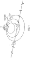
- a magnet 10 is shown relative to a first sensor 1 and a second sensor 2, according to various embodiments of the present technology.
- Each of the first sensor 1 and second sensor 2 may be a magnetic field sensor configured to sense the magnetic field generated by the magnet 10.
- each of the first sensor 1 and the second sensor 2 may be a two-dimensional (“2D") anisotropic magnetoresistive (“AMR”) sensor, which is structured to measure a magnetic field from the magnet 10, represented schematically by curved field lines 20 in FIG. 1 , in two different dimensions (e.g., x-y or y-z or x-z).
- 2D two-dimensional
- AMR anisotropic magnetoresistive
- the first sensor 1 may be spaced apart from the second sensor 2 by a distance d , so that the magnetic field at a first position corresponding to the first sensor 1 may be measured in two dimensions, and the magnetic field at a second position corresponding to the second sensor 2 may be measured in two dimensions.
- the distance d may have a value between 0.5 cm and 5 cm, or d may have any value that would be suitable for each of the first and second sensors 1, 2 to sense the magnetic field generated by the magnet 10.
- FIG. 1 illustrates two magnetic field sensors
- various alternative embodiments may include more than two magnetic field sensors configured to detect magnetic fields along two different axes at two different locations.
- four magnetic field sensors may be implemented, with two positioned at a first location and two positioned at a second location.
- Each of the four magnetic field sensors may be configured to detect the magnetic field in a single dimension, respectively, such that the combination of the four magnetic field sensors may provide magnetic field measurements in two dimensions at the first and second locations.
- the first and second sensors 1, 2 may be operatively connected to circuitry configured to process the output signals of the sensors 1, 2.
- the first and second sensors 1, 2 may be operatively connected to a programmed microprocessor, as discussed in more detail below.
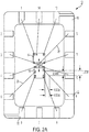
- the first sensor 1 may be structured to include circuitry 12 such as shown in FIG. 2A .
- the circuitry 12 may include a first pair comprised of a first sensor element 14 and a second sensor element 16 attached to a circuit board 18 of a chip package. Electrical wiring 28 may be used to connect the first and second sensor elements 14, 16 to contact pads 22 that, in turn, may be electrically connected to processing circuitry (e.g., a microprocessor) (not shown) to provide signals to the processing circuitry.
- processing circuitry e.g., a microprocessor
- the second sensor 2 may be structured to include circuitry similar to the circuitry 12 shown in FIG. 2A .
- the first and second sensor elements 14, 16 may have the same internal structure but may be oriented such that one is rotated by 90° relative to the other, as shown in FIG. 2A , to measure the magnetic field in two different orthogonal dimensions.
- one of the first and second sensor elements 14, 16 may measure the x-direction component ("x-component" herein) of the magnetic field
- the other of the first and second sensor elements 14, 16 may measure the z-direction component ("z-component" herein) of the magnetic field.
- the first and second sensor elements 14, 16 may be formed on a single die or on separate dies.
- FIG. 2A shows the first and second sensor elements 14, 16 to be coplanar. That is, the first and second sensor elements 14, 16 are shown to be positioned on one planar surface of the circuit board 18.
- the center-to-center distance of the first and second sensor elements 14, 16 may be in a range of approximately 0.9 mm to 1.1 mm, and the separation distance between nearest edges of the first and second sensor elements 14, 16 may be in a range of approximately 0.05 mm to 0.25 mm.
- the first and second sensor elements 14, 16 of the first and second sensors 1, 2 may be coplanar, i.e., all four sensor elements may share a common plane.
- the first and second sensor elements 14, 16 of the first sensor 1 may be coplanar on a first plane
- the first and second sensor elements 14, 16 of the second sensor 2 may be coplanar on a second plane different from the first plane.
- the first and second sensor elements 1, 2 may not be coplanar but instead may have a stacked arrangement, as schematically shown in FIG. 2B .
- the first sensor 1 may have first and second sensor elements 14-1 and 16-1 that may be stacked or overlaid in a first stacking direction perpendicular to a main surface of the circuit board 18 supporting the first and second sensor elements 14-1, 16-1.
- the second sensor 2 may have first and second sensor elements 14-2 and 16-2 that may be stacked or overlaid in a second stacking direction perpendicular to the main surface of the circuit board 18 supporting the first and second sensor elements 14-2, 16-2.
- the first and second stacking directions may be parallel to each other.
- the first and second sensor elements 14-1, 16-1 of the first sensor 1 may be rotated by 90° relative to each other, to measure the magnetic field in two different orthogonal directions.
- the first and second sensor elements 14-2, 16-2 of the second sensor 2 may be rotated by 90° relative to each other, to measure the magnetic field in two different orthogonal directions at a location different from the first sensor 1, as depicted in FIG. 2B .
- FIG. 2B shows the first sensor elements 14-1, 14-2 to be located on opposite sides of the circuit board 18 relative to the second sensor elements 16-1, 16-2, according to some embodiments of the present technology. That is, the first sensor element 14-1 and the second sensor element 16-1 of the first sensor 1 may be stacked or overlaid on opposite sides of the circuit board 18, and, similarly, the first sensor element 14-2 and the second sensor element 16-2 of the second sensor 2 may be stacked or overlaid on opposite sides of the circuit board 18.
- the circuit board 18 is shown to be transparent in FIG. 2B in order to illustrate the relative positions of the sensor elements 14-1, 14-2, 16-1, 16-2, according to some embodiments of the present technology, but need not be transparent.
- the first sensor element 14-1 and the second sensor element 16-1 may be stacked or overlaid on one side of the circuit board 18, and, similarly, the first sensor element 14-2 and the second sensor element 16-2 may be stacked or overlaid on one side of the circuit board 18.
- the first and second sensors 1, 2 may be separated by a distance d of 1 cm, and each of the first and second sensors 1, 2 may be structured to measure an x-component and a z-component of the magnetic field produced by the magnet 10, which is movable in the z-direction.
- the magnet 10 may have a size of 1 mm 3 in this non-limiting embodiment, but other sizes are possible.
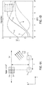
- FIG. 3B shows measurements taken by a pair of sensors in an arrangement of the type shown in FIG. 3A .
- the magnet 10 was moved in the z-direction over a distance of 3 cm, from -1 cm to 2 cm, with the "0" position corresponding to a perpendicular alignment of the magnet 10 with the first sensor 1.
- Curves 3a, 3b represent the x-component of the magnetic field measured by the first sensor 1 and the second sensor 2, respectively, as a function of distance in the z-direction.
- Curves 3c, 3d represent the z-component of the magnetic field measured by the first sensor 1 and the second sensor 2, respectively, as a function of distance in the z-direction.
- FIG. 4A schematically shows the arrangement of FIG. 3A in the presence of a stray field that is a uniform magnetic field, represented by parallel arrows.
- FIG. 4B shows the corresponding measurements taken by the first and second sensors 1, 2 in the presence of the stray field, in an arrangement of the type shown in FIG. 4A .
- Curves 4a, 4b represent the x-component of the magnetic field measured by the first sensor 1 and the second sensor 2, respectively, as a function of distance in the z-direction.
- Curves 4c, 4d represent the z-component of the magnetic field measured by the first sensor 1 and the second sensor 2, respectively, as a function of distance in the z-direction.
- FIGs. 3B and 4B A comparison of FIGs. 3B and 4B reveals that the presence of the stray field does not alter the shapes of the x-component curves 3a, 4a measured by the first sensor 1; does not alter the shapes ofthe x-component curves 3b, 4c measured by the second sensor 2; does not alter the shapes of the z-component curves 3c, 4c measured by the first sensor 1; and does not alter the shapes of the z-component curves 3d, 4d measured by the second sensor 2.
- all of the curves in FIG. 4B show a uniform upward shift to higher magnetic field values, relative to the curves in FIG. 3B , with the shift corresponding to the stray field's strength.
- the effects of the stray field on the magnetic field measurements taken by the first and second sensors 1, 2 may be eliminated by using differential field calculations. More specifically, a calculation of the difference between the curve 3a and the curve 3b (no stray field present), and the difference between the curve 4a and the curve 4b (stray field present) results in the same or nearly the same values. Therefore, differential field calculations may be used to extract useful information on the magnetic field produced by the magnet 10 even when the magnet 10 is small (e.g., 1 mm 3 ) and even when the magnetic field is measured in the presence of a stray field. That is, object position tracking systems according to some embodiments of the present technology may be substantially immune to stray magnetic fields, thus providing robust operation in a variety of applications.
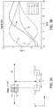
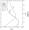
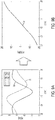
- FIG. 5 shows curves representing differential field calculations for the magnetic field measurements shown in FIG. 3B (or FIG. 4B ).
- Curve 5a represents differential values obtained by determining a difference between the curve 3b and the curve 3a (or between the curve 4b and curve the 4a).
- Curve 5b represents differential values obtained by a difference between the curve 3d and the curve 3c (or between the curve 4d and the curve 4c).
- the differential values of the curves 5a, 5b may be combined to form a single quantity representing the magnetic field of the magnetic 10. This quantity varies as a function of the magnet's position in the z-direction and therefore may be used to determine the magnet's position in the z-direction.
- the quantity representing the magnetic field of the magnet 10 is a field angle corresponding to an arctan of a differential x-component value (curve 5a) and a differential z-component value (curve 5b).
- curve 6a is derived from field angle or arctan calculations of the curves 5a, 5b.
- An example of a beneficial aspect of the curve 6a is that, if it is known that the magnet 10 has moved in the z-direction but the position of the magnet 10 along the z-direction is not known because the magnet is not visible, and if the first and second sensors 1, 2 measure a magnetic field having a field angle of 130° for the magnet 10, the curve 6a may be used to determine that the magnet 10 is at a position corresponding to +10 mm in the z-direction.
- the magnetic field of the magnet 10 changes as the magnet 10 moves in the z-direction relative to the first and second sensors 1, 2.
- the changes in the magnetic field are reproducible and therefore can be used to establish a correlation between a position of the magnet 10 along a known path, and a quantity derived from the magnetic field of the magnet 10 (e.g., a field angle corresponding to an arctan of a differential value in a first dimension and a differential value in a second dimension orthogonal to the first dimension).
- a mapping may be made of field angle as a function of distance along the path.
- a specific field angle is determined for the magnet, based on measurements by sensors such as the first and second sensors 1, 2 discussed above, then the magnet's location along the path may be determined by determining a position that corresponds or maps to the specific field angle.
- the mapping may be via a look-up table of field angle data and corresponding position data stored in association with each other.
- the mapping may be via a mathematical model correlating the field angle data and the position data (e.g., a mathematical model of the curve 6a).
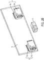
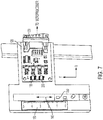
- FIG. 7 is an illustration showing an object position detection system of the type schematically shown in FIG. 4A (or FIG. 3A in the absence of a stray field).
- a first sensor 100 and a second sensor 200 are operatively attached to a circuit board 120 on which other circuitry is operatively attached.
- the circuit board 120 includes an interface 130 that is in communication with a processing circuitry (e.g., a microprocessor) (not shown). Signals from the first and second sensors 100, 200 are provided to the processing circuitry directly or via the other circuitry on the circuit board 120.
- the first and second sensors 100, 200 are arranged to sense or measure a magnetic field produced by a magnet 1000 that is slidably movable along a path 140 due to being fixed to a slidable component.
- the slidable component could be a syringe, a plunger, an automobile brake component, or another component for which it is desirable to track position.
- the path 140 extends along the y-direction.
- a scale or ruler 150 used in a testing/calibration procedure is arranged near the magnet 1000 and extends parallel to the path 140.
- the testing/calibration procedure may include:
- the first known position may be quantified (i.e., given a value) according to a position of the magnet 1000 relative to the ruler 150.
- the acts S10, S20, S30 may then be repeated for other known positions along the path 140 to obtain a sufficient number of field angles to produce a representative curve showing how field angle varies as a function of position along the path 140, an example of which is the curve 6a.
- the field angle data and the corresponding position data may be stored in association with each other in a look-up table, as discussed above.
- the representative curve may be modelled mathematically so that a position can be calculated based on magnetic field data.
- multiple sets of the first and second sensors 100, 200 may be arranged to detect a position of the magnet 1000 along different segments of the path 140.
- a first set of the first and second sensors 100, 200 may be arranged to measure an initial segment of the path 140
- a second set of the first and second sensors 100, 200 may be arranged to measure a second segment of the path 140
- a third set of the first and second sensors 100, 200 may be arranged to measure a third segment of the path 140, and so on.
- the sets of the first and second sensors 100, 200 may be arranged relative to each other such that, for example, as the magnet 1000 moves along the path 140 from the first segment to the second segment (i.e., away from the first set), the differential field obtained from the first set diminishes and the differential field obtained from the second set increases, and as the magnet moves from the second segment to the third segment (i.e., away from the second set towards the third set), the differential field obtained from the second set diminishes and the differential field obtained from the third set increases.
- end portions of adjacent segments overlap so that and there is no "dead zone" where the magnet 1000 cannot be reliably measured by any of the sets of the first and second sensors 100, 200.
- signals from the first and second sensors 100, 200 may be provided to the processing circuitry directly or via the other circuitry on the circuit board 120.
- the first sensor 100 may include x and y sensor elements 100x, 100y for measuring the x-component and the y-component of the magnetic field at the location of the first sensor 100.
- the second sensor 200 may include x and y sensor elements 200x, 200y for measuring the x-component and the y-component of the magnetic field at the location of the second sensor 200.
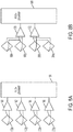
- FIGs. 8A and 8B illustrate two non-limiting examples of circuitry that may be included on the circuit board 120.
- the x and y sensor elements 100x, 100y, 200x, 200y may provide signals to respective amplifiers 160, 162, 164, 166, which in turn may provide four amplified signals to a microprocessor 180.
- the microprocessor 180 may be programmed to perform differential field and arctan calculations to determine a field angle.
- the microprocessor 180 may include circuitry to perform analog-to-digital conversion of the signals.
- the x and y sensor elements 100x, 100y, 200x, 200y may provide signals to first and second amplifiers 170, 172, such that the first amplifier 170 may receive x-component signals from the x sensor elements 100x, 200x, and the second amplifier 172 may receive y-component signals from the y sensor elements 100y, 200y.
- the first amplifier 170 may output to the microprocessor 180 a signal corresponding to a differential field calculation for the x dimension
- the second amplifier 172 may output to the microprocessor 180 a signal corresponding to a differential field calculation for the y dimension.
- the microprocessor 180 which may include circuitry to perform analog-to-digital conversion of the signals, may be programmed to perform an arctan calculation to determine a field angle from the two signals outputted by the first and second amplifiers 170, 172.
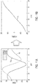
- an arrangement of the type shown in FIG. 4A (or FIG. 3A in the absence of a stray field) was used to measure the magnetic field of the magnet 10 over a wider range of travel in the z-direction (5 cm instead of the 3 cm).
- the results of differential field calculations are shown in FIG. 9A , with curve 9a corresponding to the x dimension of the measured magnetic field and curve 9b corresponding to the z dimension of the measured magnetic field.
- the differential field values of the curves 9a, 9b were used in arctan calculations to yield the curve 9c in FIG. 9B .
- first and second sensors 1, 2 may be used to track the magnet 10 in different segments of the path.
- a first set of sensors may be used to track a magnet in a first segment of a long path
- a second set of sensors may be used to track the magnet in a second segment of the long path
- a third set of sensors may be used to track the magnet in a third segment of the long path, etc.
- the first and second segments (and/or the second and third segments) may be adjacent to each other or they may have portions that overlap.
- FIG. 10A shows results of differential field calculations performed using an arrangement of the type shown in FIG. 4A (or FIG. 3A in the absence of a stray field), but using a larger magnet having a volume of 8 mm 3 .
- Curve 10a corresponds to the x dimension of the measured magnetic field
- curve 10b corresponds to the z dimension of the measured magnetic field.
- FIG. 10B although the differential field values generally are larger, owing to the larger size of the magnet 10, the field angles are similar to those of the curve 6a for the same path of the magnet 10.
- FIG. 11A shows results for differential field calculations performed using an arrangement of the type shown in FIG. 4A (or FIG. 3A in the absence of a stray field), in which an even larger magnet having a volume of 27 mm 3 is used.
- Curve 11a corresponds to the x dimension of the measured magnetic field and curve 11b corresponds to the z dimension of the measured magnetic field.
- FIG. 11B although the magnetic field values generally are larger than that of the a 1 mm 3 magnet and the 8 mm 3 magnet, the field angles are similar to those of the curve 6a for the same path of the magnet.
- aspects of the present technology allow for determination of how field angles of a magnet vary as a function of distance along a path, from which a determination of the location of the magnet along the magnet's path may be made, even when the magnet is a small-thus producing a correspondingly small magnetic field-and is in the presence of a stray field.
- the embodiments discussed herein relate to the measurement of a magnetic field in two dimensions.
- the present technology is not limited to two-dimensional measurements but may be extended to measurements in three dimensions, such as through use of 3D-AMR sensors (or other 3D magnetoresistive sensors), so that x, y, and z components of the magnetic field may be measured.
- Differential field calculations may be performed with, for example, two different pairs of the three dimensions (e.g., x-y and x-z, or x-y and y-z, or x-z and y-z) and thus yield two sets of field angles that can be used to locate a position of a magnet in two dimensions.
- Some aspects of the present technology may be embodied as one or more methods.
- the acts performed as part of a method may be ordered in any suitable way. Accordingly, embodiments may be constructed in which acts are performed in an order different than illustrated, which may include performing some acts simultaneously, even though shown as sequential acts in illustrative embodiments.
- direction and dimension may be used interchangeably herein when referencing to characteristics related to any one or any combination of: the x-axis, the y-axis, and the z-axis.
- the terms “approximately” and “about” if used herein may be construed to mean within ⁇ 20% of a target value in some embodiments, within ⁇ 10% of a target value in some embodiments, within ⁇ 5% of a target value in some embodiments, and within ⁇ 2% of a target value in some embodiments.
- the terms “approximately” and “about” may equal the target value.
- the term "substantially” if used herein may be construed to mean within 95% of a target value in some embodiments, within 98% of a target value in some embodiments, within 99% of a target value in some embodiments, and within 99.5% of a target value in some embodiments. In some embodiments, the term “substantially” may equal 100% of the target value.
Landscapes
- Physics & Mathematics (AREA)
- General Physics & Mathematics (AREA)
- Condensed Matter Physics & Semiconductors (AREA)
- Measurement Of Length, Angles, Or The Like Using Electric Or Magnetic Means (AREA)
- Transmission And Conversion Of Sensor Element Output (AREA)
Applications Claiming Priority (2)
| Application Number | Priority Date | Filing Date | Title |
|---|---|---|---|
| US201862779323P | 2018-12-13 | 2018-12-13 | |
| US16/289,476 US11573072B2 (en) | 2018-12-13 | 2019-02-28 | Magnetic position determination systems and methods |
Publications (2)
| Publication Number | Publication Date |
|---|---|
| EP3667248A1 true EP3667248A1 (fr) | 2020-06-17 |
| EP3667248B1 EP3667248B1 (fr) | 2023-05-31 |
Family
ID=68771362
Family Applications (1)
| Application Number | Title | Priority Date | Filing Date |
|---|---|---|---|
| EP19213311.4A Active EP3667248B1 (fr) | 2018-12-13 | 2019-12-03 | Systèmes et procédés de détermination de position magnétique |
Country Status (3)
| Country | Link |
|---|---|
| US (1) | US11573072B2 (fr) |
| EP (1) | EP3667248B1 (fr) |
| CN (1) | CN111322937B (fr) |
Cited By (1)
| Publication number | Priority date | Publication date | Assignee | Title |
|---|---|---|---|---|
| US12571654B2 (en) * | 2022-10-31 | 2026-03-10 | Infineon Technologies Ag | Magnetic-field-based position determination device and method for magnetic-field-based position determination |
Families Citing this family (2)
| Publication number | Priority date | Publication date | Assignee | Title |
|---|---|---|---|---|
| TWI844114B (zh) * | 2022-09-22 | 2024-06-01 | 愛盛科技股份有限公司 | 磁場感測裝置 |
| EP4575588A1 (fr) * | 2023-12-22 | 2025-06-25 | Advanced Magnetic Interaction, AMI | Suivi magnétique à grande échelle |
Citations (4)
| Publication number | Priority date | Publication date | Assignee | Title |
|---|---|---|---|---|
| EP3270112A1 (fr) * | 2016-07-11 | 2018-01-17 | Jtekt Corporation | Dispositif de moteur |
| US20180087888A1 (en) * | 2016-09-28 | 2018-03-29 | Infineon Technologies Ag | Magnetic angle sensor device and method of operation |
| EP3312564A1 (fr) * | 2016-10-20 | 2018-04-25 | Valeo Japan Co., Ltd. | Dispositif de détection d'angle de rotation et détecteur d'angle utilisé en son sein |
| US20180274896A1 (en) * | 2017-03-22 | 2018-09-27 | Tdk Corporation | Angle sensor and angle sensor system |
Family Cites Families (38)
| Publication number | Priority date | Publication date | Assignee | Title |
|---|---|---|---|---|
| US4622644A (en) * | 1984-05-10 | 1986-11-11 | Position Orientation Systems, Ltd. | Magnetic position and orientation measurement system |
| US6757557B1 (en) | 1992-08-14 | 2004-06-29 | British Telecommunications | Position location system |
| JP3186403B2 (ja) * | 1993-03-11 | 2001-07-11 | 富士通株式会社 | 磁気的センサおよび信号変換回路 |
| DE19849910A1 (de) | 1998-10-29 | 2000-05-04 | Philips Corp Intellectual Pty | Offsetkompensiertes Winkelmeßsystem |
| US6265867B1 (en) | 1999-05-19 | 2001-07-24 | Arthur D. Little, Inc. | Position encoder utilizing fluxgate sensors |
| US6516213B1 (en) | 1999-09-03 | 2003-02-04 | Robin Medical, Inc. | Method and apparatus to estimate location and orientation of objects during magnetic resonance imaging |
| US6411081B1 (en) | 2000-02-10 | 2002-06-25 | Siemens Ag | Linear position sensor using magnetic fields |
| EP1243897B1 (fr) | 2001-03-23 | 2013-12-18 | Melexis Technologies NV | Capteur de position magnétique |
| DE10162849B4 (de) | 2001-12-20 | 2007-11-29 | Sensitec Gmbh | Längenmesssystem, bei dem ein Massstab relativ zur Position von beabstandeten Längensensoren bewegt wird |
| US8321173B2 (en) | 2004-08-25 | 2012-11-27 | Wallance Daniel I | System and method for using magnetic sensors to track the position of an object |
| CN101107617A (zh) | 2004-09-27 | 2008-01-16 | 皇家飞利浦电子股份有限公司 | 用于选择显示器上指针速度的系统 |
| US7705586B2 (en) | 2004-09-27 | 2010-04-27 | Nxp B.V. | Magnetic sensor for input devices |
| JP2008514913A (ja) | 2004-09-27 | 2008-05-08 | コーニンクレッカ フィリップス エレクトロニクス エヌ ヴィ | センサー |
| FR2898189B1 (fr) | 2006-03-02 | 2008-10-17 | Moving Magnet Tech | Capteur de position a direction d'aimantation variable et procede de realisation |
| KR101659931B1 (ko) | 2007-06-27 | 2016-09-26 | 브룩스 오토메이션 인코퍼레이티드 | 다차원 위치 센서 |
| JP5014968B2 (ja) | 2007-12-07 | 2012-08-29 | 株式会社東海理化電機製作所 | ポジションセンサ |
| US7772835B2 (en) | 2008-06-16 | 2010-08-10 | Honeywell International Inc. | AMR array magnetic design for improved sensor flexibility and improved air gap performance |
| DE102010003292A1 (de) * | 2010-03-25 | 2011-09-29 | Fraunhofer-Gesellschaft zur Förderung der angewandten Forschung e.V. | Sensoranordnung und Verfahren zum Ermitteln einer Magnetisierungseinrichtung eines Gebermagneten |
| JP5062450B2 (ja) * | 2010-08-11 | 2012-10-31 | Tdk株式会社 | 回転磁界センサ |
| US8717010B2 (en) | 2011-08-19 | 2014-05-06 | Infineon Technologies Ag | Magnetic position sensors, systems and methods |
| US9448087B2 (en) | 2011-10-10 | 2016-09-20 | Methode Electronics, Inc. | Contactless magnetic linear position sensor |
| DE102012205903B4 (de) | 2012-04-11 | 2014-01-30 | Tyco Electronics Amp Gmbh | Verfahren zum berührungslosen messen einer relativen position mittels eines magnetfeldsensorarrays auf halleffektbasis und weggeber |
| WO2014153422A1 (fr) | 2013-03-19 | 2014-09-25 | Regents Of The University Of Minnesota | Système de détection de position |
| US9562758B2 (en) * | 2013-04-15 | 2017-02-07 | Stemco Kaiser Incorporated | Distance measurement sensor based on magnetic signal triangulation |
| US9803997B2 (en) | 2013-07-26 | 2017-10-31 | Bei Sensors & Systems Company, Inc. | System and method for determining absolute angular position of a rotating member |
| EP3025126B1 (fr) | 2013-07-26 | 2018-01-17 | BEI Sensors & Systems Company Inc. | Système de détection pour position angulaire absolue |
| US9389283B2 (en) | 2013-07-26 | 2016-07-12 | Sensata Technologies, Inc. | System and method for converting output of sensors to absolute angular position of a rotating member |
| US9625535B2 (en) | 2013-08-07 | 2017-04-18 | Allegro Microsystems, Llc | Systems and methods for computing a position of a magnetic target |
| US9852832B2 (en) | 2014-06-25 | 2017-12-26 | Allegro Microsystems, Llc | Magnetic field sensor and associated method that can sense a position of a magnet |
| US9797746B2 (en) * | 2014-12-23 | 2017-10-24 | Allegro Microsystems, Llc | Systems and methods for detecting a magnetic target by computing a barycenter |
| JP6191840B2 (ja) * | 2015-07-31 | 2017-09-06 | Tdk株式会社 | 角度センサの補正装置および補正方法ならびに角度センサ |
| US9835472B2 (en) | 2015-09-25 | 2017-12-05 | Infineon Technologies Ag | Using cartesian coordinates for position detection with a magnetic sensor |
| DE102016218530A1 (de) | 2016-09-27 | 2018-03-29 | Te Connectivity Germany Gmbh | Weggeber zum berührungslosen Messen einer relativen Position, Herstellungsverfahren für eine Magnetfeldsensoranordnung und Magnetfeldsensor |
| JP6536632B2 (ja) | 2016-12-09 | 2019-07-03 | Tdk株式会社 | 角度センサおよび角度センサシステム |
| US10816363B2 (en) * | 2018-02-27 | 2020-10-27 | Nxp B.V. | Angular sensor system and method of stray field cancellation |
| EP4614112A3 (fr) | 2018-06-26 | 2025-12-03 | Melexis Technologies SA | Système et procédé de capteur de position, robustes contre les champs perturbateurs |
| US10914611B2 (en) * | 2018-08-27 | 2021-02-09 | Nxp B.V. | Magnetic field sensor system and method for rotation angle measurement |
| EP3650816B1 (fr) | 2018-11-12 | 2021-01-27 | Melexis Technologies SA | Système et procédé de capteur de position magnétique |
-
2019
- 2019-02-28 US US16/289,476 patent/US11573072B2/en active Active
- 2019-12-03 EP EP19213311.4A patent/EP3667248B1/fr active Active
- 2019-12-13 CN CN201911278499.1A patent/CN111322937B/zh active Active
Patent Citations (4)
| Publication number | Priority date | Publication date | Assignee | Title |
|---|---|---|---|---|
| EP3270112A1 (fr) * | 2016-07-11 | 2018-01-17 | Jtekt Corporation | Dispositif de moteur |
| US20180087888A1 (en) * | 2016-09-28 | 2018-03-29 | Infineon Technologies Ag | Magnetic angle sensor device and method of operation |
| EP3312564A1 (fr) * | 2016-10-20 | 2018-04-25 | Valeo Japan Co., Ltd. | Dispositif de détection d'angle de rotation et détecteur d'angle utilisé en son sein |
| US20180274896A1 (en) * | 2017-03-22 | 2018-09-27 | Tdk Corporation | Angle sensor and angle sensor system |
Cited By (1)
| Publication number | Priority date | Publication date | Assignee | Title |
|---|---|---|---|---|
| US12571654B2 (en) * | 2022-10-31 | 2026-03-10 | Infineon Technologies Ag | Magnetic-field-based position determination device and method for magnetic-field-based position determination |
Also Published As
| Publication number | Publication date |
|---|---|
| CN111322937A (zh) | 2020-06-23 |
| EP3667248B1 (fr) | 2023-05-31 |
| CN111322937B (zh) | 2022-04-19 |
| US11573072B2 (en) | 2023-02-07 |
| US20200191546A1 (en) | 2020-06-18 |
Similar Documents
| Publication | Publication Date | Title |
|---|---|---|
| US8378675B2 (en) | Current sensor, current measuring module and method for measuring current | |
| CN108020150B (zh) | 使用磁传感器的多维测量以及相关系统、方法和集成电路 | |
| US9835472B2 (en) | Using cartesian coordinates for position detection with a magnetic sensor | |
| CN104220844B (zh) | 借助磁场传感器阵列基于霍耳效应非接触测量相对位置的位移传感器 | |
| JP5620475B2 (ja) | 磁気によって位置を求めるための方法及び装置 | |
| EP3469314B1 (fr) | Capteur de champ magnétique pour détecter la proximité et/ou l'emplacement d'un objet | |
| CN102841232A (zh) | 电线用电流传感器 | |
| CN102954807A (zh) | 磁性位置传感器、系统和方法 | |
| EP3667248B1 (fr) | Systèmes et procédés de détermination de position magnétique | |
| US9958511B2 (en) | Soft switching of magnetization in a magnetoresistive sensor | |
| US10295616B2 (en) | Magnetic field imaging system | |
| CN104204730A (zh) | 借助于3d霍尔传感器非接触地测量相对位置的方法 | |
| CN108227005A (zh) | 一种目标定位及识别方法 | |
| CN105277108A (zh) | 位置检测装置 | |
| US11313922B2 (en) | Signal processing circuit and magnetic sensor system | |
| CN113466948A (zh) | 一种煤岩破坏电磁辐射测向定位系统 | |
| CN106164621B (zh) | 用于检测在运动的部件上的位移的传感器组件 | |
| CN116736199A (zh) | 一种空间静态磁场分布测量系统及方法 | |
| US10008064B2 (en) | Measuring device for measuring magnetic properties of the surroundings of the measuring device | |
| US11280637B2 (en) | High performance magnetic angle sensor | |
| US11585676B2 (en) | Magnetic field measuring device | |
| US12352831B2 (en) | Dual current magnetic field sensor | |
| WO2018199068A1 (fr) | Capteur magnétique | |
| US9816838B2 (en) | Magnetoresistive angle sensor with linear sensor elements | |
| Bukunov et al. | Modeling of magnetic label field sensing by GMR structure |
Legal Events
| Date | Code | Title | Description |
|---|---|---|---|
| PUAI | Public reference made under article 153(3) epc to a published international application that has entered the european phase |
Free format text: ORIGINAL CODE: 0009012 |
|
| STAA | Information on the status of an ep patent application or granted ep patent |
Free format text: STATUS: THE APPLICATION HAS BEEN PUBLISHED |
|
| AK | Designated contracting states |
Kind code of ref document: A1 Designated state(s): AL AT BE BG CH CY CZ DE DK EE ES FI FR GB GR HR HU IE IS IT LI LT LU LV MC MK MT NL NO PL PT RO RS SE SI SK SM TR |
|
| AX | Request for extension of the european patent |
Extension state: BA ME |
|
| STAA | Information on the status of an ep patent application or granted ep patent |
Free format text: STATUS: REQUEST FOR EXAMINATION WAS MADE |
|
| 17P | Request for examination filed |
Effective date: 20201119 |
|
| RBV | Designated contracting states (corrected) |
Designated state(s): AL AT BE BG CH CY CZ DE DK EE ES FI FR GB GR HR HU IE IS IT LI LT LU LV MC MK MT NL NO PL PT RO RS SE SI SK SM TR |
|
| STAA | Information on the status of an ep patent application or granted ep patent |
Free format text: STATUS: EXAMINATION IS IN PROGRESS |
|
| 17Q | First examination report despatched |
Effective date: 20210310 |
|
| GRAP | Despatch of communication of intention to grant a patent |
Free format text: ORIGINAL CODE: EPIDOSNIGR1 |
|
| STAA | Information on the status of an ep patent application or granted ep patent |
Free format text: STATUS: GRANT OF PATENT IS INTENDED |
|
| INTG | Intention to grant announced |
Effective date: 20221222 |
|
| GRAS | Grant fee paid |
Free format text: ORIGINAL CODE: EPIDOSNIGR3 |
|
| GRAA | (expected) grant |
Free format text: ORIGINAL CODE: 0009210 |
|
| STAA | Information on the status of an ep patent application or granted ep patent |
Free format text: STATUS: THE PATENT HAS BEEN GRANTED |
|
| AK | Designated contracting states |
Kind code of ref document: B1 Designated state(s): AL AT BE BG CH CY CZ DE DK EE ES FI FR GB GR HR HU IE IS IT LI LT LU LV MC MK MT NL NO PL PT RO RS SE SI SK SM TR |
|
| REG | Reference to a national code |
Ref country code: GB Ref legal event code: FG4D Ref country code: CH Ref legal event code: EP |
|
| REG | Reference to a national code |
Ref country code: DE Ref legal event code: R096 Ref document number: 602019029500 Country of ref document: DE |
|
| REG | Reference to a national code |
Ref country code: AT Ref legal event code: REF Ref document number: 1571169 Country of ref document: AT Kind code of ref document: T Effective date: 20230615 |
|
| REG | Reference to a national code |
Ref country code: IE Ref legal event code: FG4D |
|
| REG | Reference to a national code |
Ref country code: LT Ref legal event code: MG9D |
|
| REG | Reference to a national code |
Ref country code: NL Ref legal event code: MP Effective date: 20230531 |
|
| REG | Reference to a national code |
Ref country code: AT Ref legal event code: MK05 Ref document number: 1571169 Country of ref document: AT Kind code of ref document: T Effective date: 20230531 |
|
| PG25 | Lapsed in a contracting state [announced via postgrant information from national office to epo] |
Ref country code: SE Free format text: LAPSE BECAUSE OF FAILURE TO SUBMIT A TRANSLATION OF THE DESCRIPTION OR TO PAY THE FEE WITHIN THE PRESCRIBED TIME-LIMIT Effective date: 20230531 Ref country code: NO Free format text: LAPSE BECAUSE OF FAILURE TO SUBMIT A TRANSLATION OF THE DESCRIPTION OR TO PAY THE FEE WITHIN THE PRESCRIBED TIME-LIMIT Effective date: 20230831 Ref country code: ES Free format text: LAPSE BECAUSE OF FAILURE TO SUBMIT A TRANSLATION OF THE DESCRIPTION OR TO PAY THE FEE WITHIN THE PRESCRIBED TIME-LIMIT Effective date: 20230531 Ref country code: AT Free format text: LAPSE BECAUSE OF FAILURE TO SUBMIT A TRANSLATION OF THE DESCRIPTION OR TO PAY THE FEE WITHIN THE PRESCRIBED TIME-LIMIT Effective date: 20230531 |
|
| PG25 | Lapsed in a contracting state [announced via postgrant information from national office to epo] |
Ref country code: RS Free format text: LAPSE BECAUSE OF FAILURE TO SUBMIT A TRANSLATION OF THE DESCRIPTION OR TO PAY THE FEE WITHIN THE PRESCRIBED TIME-LIMIT Effective date: 20230531 Ref country code: PL Free format text: LAPSE BECAUSE OF FAILURE TO SUBMIT A TRANSLATION OF THE DESCRIPTION OR TO PAY THE FEE WITHIN THE PRESCRIBED TIME-LIMIT Effective date: 20230531 Ref country code: NL Free format text: LAPSE BECAUSE OF FAILURE TO SUBMIT A TRANSLATION OF THE DESCRIPTION OR TO PAY THE FEE WITHIN THE PRESCRIBED TIME-LIMIT Effective date: 20230531 Ref country code: LV Free format text: LAPSE BECAUSE OF FAILURE TO SUBMIT A TRANSLATION OF THE DESCRIPTION OR TO PAY THE FEE WITHIN THE PRESCRIBED TIME-LIMIT Effective date: 20230531 Ref country code: LT Free format text: LAPSE BECAUSE OF FAILURE TO SUBMIT A TRANSLATION OF THE DESCRIPTION OR TO PAY THE FEE WITHIN THE PRESCRIBED TIME-LIMIT Effective date: 20230531 Ref country code: IS Free format text: LAPSE BECAUSE OF FAILURE TO SUBMIT A TRANSLATION OF THE DESCRIPTION OR TO PAY THE FEE WITHIN THE PRESCRIBED TIME-LIMIT Effective date: 20230930 Ref country code: HR Free format text: LAPSE BECAUSE OF FAILURE TO SUBMIT A TRANSLATION OF THE DESCRIPTION OR TO PAY THE FEE WITHIN THE PRESCRIBED TIME-LIMIT Effective date: 20230531 Ref country code: GR Free format text: LAPSE BECAUSE OF FAILURE TO SUBMIT A TRANSLATION OF THE DESCRIPTION OR TO PAY THE FEE WITHIN THE PRESCRIBED TIME-LIMIT Effective date: 20230901 |
|
| P01 | Opt-out of the competence of the unified patent court (upc) registered |
Effective date: 20231106 |
|
| PG25 | Lapsed in a contracting state [announced via postgrant information from national office to epo] |
Ref country code: FI Free format text: LAPSE BECAUSE OF FAILURE TO SUBMIT A TRANSLATION OF THE DESCRIPTION OR TO PAY THE FEE WITHIN THE PRESCRIBED TIME-LIMIT Effective date: 20230531 |
|
| PG25 | Lapsed in a contracting state [announced via postgrant information from national office to epo] |
Ref country code: SK Free format text: LAPSE BECAUSE OF FAILURE TO SUBMIT A TRANSLATION OF THE DESCRIPTION OR TO PAY THE FEE WITHIN THE PRESCRIBED TIME-LIMIT Effective date: 20230531 |
|
| PG25 | Lapsed in a contracting state [announced via postgrant information from national office to epo] |
Ref country code: SM Free format text: LAPSE BECAUSE OF FAILURE TO SUBMIT A TRANSLATION OF THE DESCRIPTION OR TO PAY THE FEE WITHIN THE PRESCRIBED TIME-LIMIT Effective date: 20230531 Ref country code: SK Free format text: LAPSE BECAUSE OF FAILURE TO SUBMIT A TRANSLATION OF THE DESCRIPTION OR TO PAY THE FEE WITHIN THE PRESCRIBED TIME-LIMIT Effective date: 20230531 Ref country code: RO Free format text: LAPSE BECAUSE OF FAILURE TO SUBMIT A TRANSLATION OF THE DESCRIPTION OR TO PAY THE FEE WITHIN THE PRESCRIBED TIME-LIMIT Effective date: 20230531 Ref country code: PT Free format text: LAPSE BECAUSE OF FAILURE TO SUBMIT A TRANSLATION OF THE DESCRIPTION OR TO PAY THE FEE WITHIN THE PRESCRIBED TIME-LIMIT Effective date: 20231002 Ref country code: EE Free format text: LAPSE BECAUSE OF FAILURE TO SUBMIT A TRANSLATION OF THE DESCRIPTION OR TO PAY THE FEE WITHIN THE PRESCRIBED TIME-LIMIT Effective date: 20230531 Ref country code: DK Free format text: LAPSE BECAUSE OF FAILURE TO SUBMIT A TRANSLATION OF THE DESCRIPTION OR TO PAY THE FEE WITHIN THE PRESCRIBED TIME-LIMIT Effective date: 20230531 Ref country code: CZ Free format text: LAPSE BECAUSE OF FAILURE TO SUBMIT A TRANSLATION OF THE DESCRIPTION OR TO PAY THE FEE WITHIN THE PRESCRIBED TIME-LIMIT Effective date: 20230531 |
|
| REG | Reference to a national code |
Ref country code: DE Ref legal event code: R097 Ref document number: 602019029500 Country of ref document: DE |
|
| PLBE | No opposition filed within time limit |
Free format text: ORIGINAL CODE: 0009261 |
|
| STAA | Information on the status of an ep patent application or granted ep patent |
Free format text: STATUS: NO OPPOSITION FILED WITHIN TIME LIMIT |
|
| PG25 | Lapsed in a contracting state [announced via postgrant information from national office to epo] |
Ref country code: SI Free format text: LAPSE BECAUSE OF FAILURE TO SUBMIT A TRANSLATION OF THE DESCRIPTION OR TO PAY THE FEE WITHIN THE PRESCRIBED TIME-LIMIT Effective date: 20230531 |
|
| 26N | No opposition filed |
Effective date: 20240301 |
|
| PG25 | Lapsed in a contracting state [announced via postgrant information from national office to epo] |
Ref country code: SI Free format text: LAPSE BECAUSE OF FAILURE TO SUBMIT A TRANSLATION OF THE DESCRIPTION OR TO PAY THE FEE WITHIN THE PRESCRIBED TIME-LIMIT Effective date: 20230531 Ref country code: IT Free format text: LAPSE BECAUSE OF FAILURE TO SUBMIT A TRANSLATION OF THE DESCRIPTION OR TO PAY THE FEE WITHIN THE PRESCRIBED TIME-LIMIT Effective date: 20230531 |
|
| REG | Reference to a national code |
Ref country code: CH Ref legal event code: PL |
|
| PG25 | Lapsed in a contracting state [announced via postgrant information from national office to epo] |
Ref country code: LU Free format text: LAPSE BECAUSE OF NON-PAYMENT OF DUE FEES Effective date: 20231203 |
|
| PG25 | Lapsed in a contracting state [announced via postgrant information from national office to epo] |
Ref country code: MC Free format text: LAPSE BECAUSE OF FAILURE TO SUBMIT A TRANSLATION OF THE DESCRIPTION OR TO PAY THE FEE WITHIN THE PRESCRIBED TIME-LIMIT Effective date: 20230531 |
|
| REG | Reference to a national code |
Ref country code: BE Ref legal event code: MM Effective date: 20231231 |
|
| PG25 | Lapsed in a contracting state [announced via postgrant information from national office to epo] |
Ref country code: MC Free format text: LAPSE BECAUSE OF FAILURE TO SUBMIT A TRANSLATION OF THE DESCRIPTION OR TO PAY THE FEE WITHIN THE PRESCRIBED TIME-LIMIT Effective date: 20230531 Ref country code: LU Free format text: LAPSE BECAUSE OF NON-PAYMENT OF DUE FEES Effective date: 20231203 |
|
| REG | Reference to a national code |
Ref country code: IE Ref legal event code: MM4A |
|
| PG25 | Lapsed in a contracting state [announced via postgrant information from national office to epo] |
Ref country code: IE Free format text: LAPSE BECAUSE OF NON-PAYMENT OF DUE FEES Effective date: 20231203 |
|
| PG25 | Lapsed in a contracting state [announced via postgrant information from national office to epo] |
Ref country code: BE Free format text: LAPSE BECAUSE OF NON-PAYMENT OF DUE FEES Effective date: 20231231 |
|
| PG25 | Lapsed in a contracting state [announced via postgrant information from national office to epo] |
Ref country code: CH Free format text: LAPSE BECAUSE OF NON-PAYMENT OF DUE FEES Effective date: 20231231 |
|
| PG25 | Lapsed in a contracting state [announced via postgrant information from national office to epo] |
Ref country code: IE Free format text: LAPSE BECAUSE OF NON-PAYMENT OF DUE FEES Effective date: 20231203 Ref country code: CH Free format text: LAPSE BECAUSE OF NON-PAYMENT OF DUE FEES Effective date: 20231231 Ref country code: BE Free format text: LAPSE BECAUSE OF NON-PAYMENT OF DUE FEES Effective date: 20231231 |
|
| PG25 | Lapsed in a contracting state [announced via postgrant information from national office to epo] |
Ref country code: BG Free format text: LAPSE BECAUSE OF FAILURE TO SUBMIT A TRANSLATION OF THE DESCRIPTION OR TO PAY THE FEE WITHIN THE PRESCRIBED TIME-LIMIT Effective date: 20230531 |
|
| PG25 | Lapsed in a contracting state [announced via postgrant information from national office to epo] |
Ref country code: BG Free format text: LAPSE BECAUSE OF FAILURE TO SUBMIT A TRANSLATION OF THE DESCRIPTION OR TO PAY THE FEE WITHIN THE PRESCRIBED TIME-LIMIT Effective date: 20230531 |
|
| PG25 | Lapsed in a contracting state [announced via postgrant information from national office to epo] |
Ref country code: CY Free format text: LAPSE BECAUSE OF FAILURE TO SUBMIT A TRANSLATION OF THE DESCRIPTION OR TO PAY THE FEE WITHIN THE PRESCRIBED TIME-LIMIT; INVALID AB INITIO Effective date: 20191203 |
|
| PG25 | Lapsed in a contracting state [announced via postgrant information from national office to epo] |
Ref country code: HU Free format text: LAPSE BECAUSE OF FAILURE TO SUBMIT A TRANSLATION OF THE DESCRIPTION OR TO PAY THE FEE WITHIN THE PRESCRIBED TIME-LIMIT; INVALID AB INITIO Effective date: 20191203 |
|
| PG25 | Lapsed in a contracting state [announced via postgrant information from national office to epo] |
Ref country code: TR Free format text: LAPSE BECAUSE OF FAILURE TO SUBMIT A TRANSLATION OF THE DESCRIPTION OR TO PAY THE FEE WITHIN THE PRESCRIBED TIME-LIMIT Effective date: 20230531 |
|
| PGFP | Annual fee paid to national office [announced via postgrant information from national office to epo] |
Ref country code: DE Payment date: 20251126 Year of fee payment: 7 |
|
| PGFP | Annual fee paid to national office [announced via postgrant information from national office to epo] |
Ref country code: GB Payment date: 20251119 Year of fee payment: 7 |
|
| PGFP | Annual fee paid to national office [announced via postgrant information from national office to epo] |
Ref country code: FR Payment date: 20251120 Year of fee payment: 7 |